智恩科技控制柜FCO1说明书通用
- 格式:doc
- 大小:1.93 MB
- 文档页数:12

P L C控制柜基础知识(总7页) -CAL-FENGHAI.-(YICAI)-Company One1-CAL-本页仅作为文档封面,使用请直接删除PLC控制柜基础知识PLC控制柜是指成套的控制柜,可实现电机,开关的控制的电气柜。
PLC控制柜有过载、短路、缺相保护等功能。
其结构紧凑、工作稳定、功能齐全,可以根据实际控制规摸大小进行组合,既可以实现单柜自动控制,也可以实现多柜通过工业以太网或工业现场总线网络组成集散(DSC)控制系统,能适应各种大小规模的工业自动化控制场合,被广泛应用在电力、冶金、化工、造纸、环保污水处理等行业中。
PLC控制柜可完成设备自动化和过程自动化控制,实现完美的网络功能,性能稳定、可扩展、抗干扰强等特点,是现代工业的核心和灵魂。
用户可以根据自身需求设计PLC控制柜、变频柜等,并可搭配人机界面触摸屏,达到轻松操作的目的。
典型应用有恒压供水、空压机、风机水泵、中央空调、港口机械、机床、锅炉、造纸机械、食品机械等等。
下面就给大家普及一下基础知识~PLC控制柜的组成部分1.空开一个总的空气开关,这是整个柜体的电源控制,是每个柜子都必须要有的东西。
这个要根据工程需要选择。
如果工程小,可以直接用一个一体化的PLC;如果工程比较大,可能就需要模块、卡件式的,同时还可能需要冗余(也就是两套交替使用)。
的电源一个24VDC的开关电源,大多数的PLC都是自带24VDC的电源,需要根据实际情况来定是否要这个开关电源。
4.继电器一般PLC是可以直接将指令发到控制回路里的,但也可能先由继电器中转。
如果你PLC的输出口带电是24VDC的,但是你的控制回路里画的图需要PLC供的节点却是220VAC的,那么你就必须在PLC输出口加上一个继电器,即指令发出时继电器动作,让控制回路的节点接到继电器的常开或常闭点上。
这也是根据情况选择是否使用继电器。
5.接线端子这个肯定是每个柜子都必不可少的东西,根据信号数量可以配置。

PCS-9611C线路保护装置技术和使用说明书PCS-9611C 线路保护装置前言使用产品前,请仔细阅读本章节!本章叙述了使用产品前的安全预防建议。
在安装和使用时,本章内容必须全部阅读且充分理解。
忽略说明书中相关警示说明,因不当操作造成的任何损害,本公司不承担相应责任。
在对本装置做任何操作前,相关专业人员必须仔细阅读本说明书,熟悉操作相关内容。
操作指导及警告本手册中将会用到以下指示标记和标准定义:危险! 意味着如果安全预防措施被忽视,则会导致人员死亡,严重的人身伤害,或严重的设备损坏。
警告!意味着如果安全预防措施被忽视,则可能导致人员死亡,严重的人身伤害,或严重的设备损坏。
警示!意味着如果安全预防措施被忽视,则可能导致轻微的人身伤害或设备损坏。
本条特别适用于对装置的损坏及可能对被保护设备的损坏。
警告!为增强或修改现有功能,装置的软硬件均可能升级,请确认此版本使用手册和您购买的产品相兼容。
警告!电气设备在运行时,这些装置的某些部件可能带有高压。
不正确的操作可能导致严重的人身伤害或设备损坏。
只有具备资质的合格专业工作人员才允许对装置或在装置临近工作。
工作人员需熟知本手册中所提到的注意事项和工作流程,以及安全规定。
特别注意,一些通用的工作于高压带电设备的工作规则必须遵守。
如果不遵守可能导致严重的人身伤亡或设备损坏。
危险!在一次系统带电运行时,绝对不允许将与装置连接的电流互感器二次开路。
该回路开路可能会产生极端危险的高压。
PCS-9611C 线路保护装置警告!●曝露端子在装置带电时不要触碰曝露的端子等,因为可能会产生危险的高电压。
●残余电压在装置电源关闭后,直流回路中仍然可能存在危险的电压。
这些电压需在数秒钟后才会消失。
警示!●接地装置的接地端子必须可靠接地。
●运行环境该装置只允许运行在技术参数所规定的大气环境中,而且运行环境不能存在不正常的震动。
●额定值在接入交流电压电流回路或直流电源回路时,请确认它们符合装置的额定参数。

河北优脉产品手册河北优脉产品手册外呼、全通型控制器(ETK-EC01)河北优脉产品手册目录一.系统简介 (3)二.系统组成 (3)三.系统主控部分技术参数 (3)四.功能介绍 (3)五.设备图片 (4)六.端口及设置开关说明 (6)七.内呼全控型安装接线图 (6)八.外呼控制型安装接线图 (7)九.系统调试 (7)十.常见故障处理 (8)十一.注意事项 (8)河北优脉产品手册一.系统简介电梯IC卡管理系统可以对电梯乘坐人员进行电脑智能化控制和管理,有效防止闲杂人员任意乘用电梯出入大厦,从而提高大厦的安全管理水平。
电梯IC卡管理系统采用一人一卡,指定权限,凭卡乘梯。
每张卡能到达的楼层,由物业管理部门发卡时指定。
持卡人只有在指定的楼层才可进行按键选择,召唤电梯,停靠所要到达的楼层;在非指定的楼层既不能召唤,也不能停靠。
本系统只改变电梯选层权限功能,而不改变电梯运行功能。
在电梯原有功能基础上增加管理功能。
采用非接触式IC卡控制,占用卡内两个扇区,可与其它系统合用同一卡片,实现区域一卡通功能。
二.系统组成系统由硬件和软件二大部分组成。
硬件包括主控制器、读卡天线、电源、写卡器、IC卡片等组成控制系统,软件包括下位机运行控制软件、上位机写卡授权软件。
三.系统主控部分技术参数1.输入电压:DC12V~36V2.输入电流:<70mA3.手动、消防端口输入电压:DC12V~DC24V4.主控板输出点:3路5.输出点特性:开关量输出6.使用温度:-10~60摄氏度,工作环境湿度为RH 30%~95%不结露,7.存储温度:-20~70摄氏度8.刷卡操作时间:<100ms9.射频通讯距离:<10m10.存储历史刷卡记录:最多6000条(循环存储)11.最多梯号25512.外型尺寸:见设备图片13.定位孔尺寸:见设备图片14.平均无故障时间:>20000小时15.平均维修时间: <0.5小时四.功能介绍系统结构紧凑,功能强大。

ESTUN机器人S1E控制柜使用说明书E-0701CN-02感谢您使用埃斯顿机器人产品。
在使用机器人之前,务必仔细阅读机器人安全使用须知,并在理解该内容的基础上使用机器人。
本公司致力于不断提升产品品质,本手册中与产品有关的规格和信息如有改动,恕不另行通知。
本手册中所有陈述、信息和建议均已经过慎重处理,但不保证完全正确。
本公司对于因使用本手册而造成的直接或间接损失不负任何责任。
用户必须对其应用任何产品负全部责任,须谨慎使用本手册及产品。
本手册所有内容的解释权属南京埃斯顿机器人工程有限公司。
本手册未对任何一方授权许可,不得以任何方式复制和拷贝其中的全部或部分内容。
版权所有:南京埃斯顿机器人工程有限公司产品服务热线:400-025-3336地址:南京市江宁经济开发区吉印大道1888号邮编:211102电话:************公司主页:电子邮箱:***************修订记录版本年月变更内容01 2022.09 新建手册。
02 2023.03 更新外形尺寸图,控制器示意图。
删除ER20-1745-PV机型、更新基本参数章节安全使用须知本章说明为安全使用机器人而需要遵守的内容。
在使用机器人之前,务必熟读并理解本章中所述内容。
使用埃斯顿机器人的公司、个人应该熟读所在地区、国家的标准和法律,并且安装适当的安全设施保护机器人的使用人员。
使用前(安装、运转、保养、检修),请务必熟读并全部掌握本说明书和其他附属资料,在熟知全部设备知识、安全知识及注意事项后再开始使用。
但是使用人员即使完全按照手册中给出的所有安全信息进行,埃斯顿公司也无法保证使用人员不会受到任何伤害。
使用人员的定义使用人员的定义如下所示。
1.操作人员⚫进行机器人电源ON/OFF操作;⚫从操作面板启动机器人程序;⚫恢复系统报警状态;⚫操作者不得在安全栅栏内进行作业。
2.程序人员⚫进行机器人的操作;⚫在安全区域内进行机器人的示教等;⚫可以在安全区域内进行作业;⚫上述人员必须接受针对机器人的专业培训。

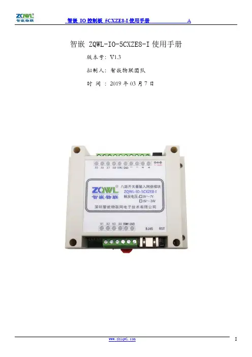
智嵌 ZQWL-IO-5CXZE8-I使用手册版本号:V1.3拟制人:智嵌物联团队时间:2019年03月7日目录前言 (3)1产品快速入门 (3)1.1硬件准备 (3)1.2使用网络控制软件 (4)1.3使用网络调试助手控制 (6)2硬件功能介绍 (7)2.1网络特性 (7)2.2硬件特点 (8)3模块硬件接口 (8)3.1模块接口及尺寸 (8)4模块输入接线 (9)4.1模块电源输入 (9)4.2模块开关量输入 (9)4.3模块开关量输入状态自动上报 (10)5模块参数配置 (11)5.1智嵌网络IO配置软件 (11)5.2网页参数配置 (13)6模块复位以及固件升级 (17)6.1模块复位 (17)6.2模块固件升级 (18)7模块通讯协议 (18)7.1自定义协议 (18)1、控制指令 (18)2、配置指令 (19)7.2Modbus rtu协议 (20)7.3Modbus rtu 指令码举例 (20)7.4Modbus TCP协议 (21)8与网络型IO输出模块成对使用 (22)8.1开关量输入/输出模块的设置 (22)前言智嵌物联系列产品命名规则一览:产品类型IO:IO 控制板系列EthRS:串口服务器系列SS:传感器系列AN:模拟量板卡系列GPRS:GPRS dtu 系列CANET:can 转网络系列RCAN:can 转串口系列RF:射频识别系列ZB :zigbee 通讯系列FiB:光纤转换系列智嵌物联IO 控制板系列产品命名规则如下:如:ZQWL-IO-1CNRC16-I12V 供电/带外壳/NPN 输入/10A 电流/网络+串口/16路输出/通讯隔离B :不带C :带外壳N:NPN 输入P:PNP 输入X:兼容N 和P T:TTL 模块A:模拟量输入Z:无输入Z:无输出A:固态交流D:固态直流R:电流10A T:晶体管输出L:TTL 模块0:电流16A 3:电流30A 5:电流50AE:网络W:wifi A:串口+CAN C:网络+串口D:网络+wifiZ:网络+串口+wifi G:GPRS+串口8:8路输出16:16路输出32:32路输出1:12VDC 2:24VDC -I :通讯隔离3:3.3VDC 4:220VAC 5:5~36VDC 6:POE 供电1 产品快速入门ZQWL-IO-5CXZE8-I (以下简称控制板)是一款可通过网络远程传输的8路NPN/PNP 兼容型光电输入控制板。

Your Global Automation PartnerIntegration with ABB Control Builder M via PROFIBUSIntegration Manual2HansTurckGmbH&Co.KG|T+492084952-0|F+492084952-264|**************|Contents1About this manual (5)1.1Target groups (5)1.2Explanation of symbols used (5)1.3Other documents (5)1.4Feedback about these instructions (5)2Notes on the system (6)2.1System identification (6)2.2Turck service (6)3For your safety (7)3.1Intended use (7)3.2General safety notes (7)3.3Notes on Ex protection (7)4Integrating an excom system in ABB Compact Control Builder M (8)4.1Requirements (8)4.1.1Hardware requirements (8)4.1.2Software requirements (9)4.2Installing a GSD configuration file (9)4.3Defining the GSD signal (11)4.3.1Setting GSD signals for individual modules (15)4.3.2GSD signals – setting diagnostics (24)4.4Adding excom I/O modules to the AC 800M (27)4.5Setting excom I/O module parameters (29)4.6Configuring I/O data (31)4.7Loading the current configuration into the AC 800M (34)4.8Online mode (35)5Turck subsidiaries — contact information (36)V01.00 | 2022/063Contents4HansTurckGmbH&Co.KG|T+492084952-0|F+492084952-264|**************|V01.00 | 2022/0651About this manualThe manual describes the integration of the excom system in the ABB Compact Control Builder M control system for AC 800M via PROFIBUS-DP.Read this manual and the applicable documents carefully before the integration. This will prevent the risk of personal injury and damage to property. Keep this manual safe during the service life of the product. If the product is passed on, hand over this manual as well.The manual describes the possibilities for GSD-based integration from the installation right through to the handling of the I/O data and the associated diagnostics.1.1Target groupsThese instructions are written for specifically trained personnel and must be read carefully by anyone entrusted with the commissioning, operation and maintenance of the system.When using the device in Ex circuits, the user must also have an additional knowledge of explosion protection (IEC/EN 60079-14 etc.).1.2Explanation of symbols usedThe following symbols are used in these instructions:uCALL TO ACTION This symbol denotes actions that the user must carry out.a RESULTS OF ACTION This symbol denotes relevant results of actions.1.3Other documentsBesides this document the following material can be found on the Internet at :nData sheets nQuick start guide nexcom manuals n Approvals1.4Feedback about these instructionsWe make every effort to ensure that these instructions are as informative and as clear as pos-sible. If you have any suggestions for improving the design or if some information is missing in the document, please send your suggestions to *****************.Notes on the systemTurck service2Notes on the system2.1System identificationThis manual applies to the following PROFIBUS DP gateways for excom:n GDP-N…n GDP-IS…2.2Turck serviceTurck supports you with your projects, from initial analysis to the commissioning of your applic-ation. The Turck product database under contains software tools for program-ming, configuration or commissioning, data sheets and CAD files in numerous export formats.The contact details of Turck subsidiaries worldwide can be found on p. [} 36].6HansTurckGmbH&Co.KG|T+492084952-0|F+492084952-264|**************|3For your safetyThe product is designed according to state-of-the-art technology. However, residual risks stillexist. Observe the following warnings and safety notices to prevent damage to persons andproperty. Turck accepts no liability for damage caused by failure to observe these warning andsafety notices.3.1Intended useThe excom system is integrated in ABB Control Builder M via PROFIBUS-DP using a GDP file.The devices may only be used as described in these instructions. Any other use is not in accord-ance with the intended use. Turck accepts no liability for any resulting damage.3.2General safety notesn The device may only be assembled, installed, operated, parameterized and maintained by professionally-trained personnel.n The device may only be used in accordance with applicable national and internationalregulations, standards and laws.n The device meets the EMC requirements for industrial areas. When used in residential areas, take measures to avoid radio interference.3.3Notes on Ex protectionn Only use the device in Ex areas when installed in the appropriate protective housing.n Observe national and international regulations for explosion protection.n When operating the device in a hazardous area, the user must have a working knowledge of explosion protection (IEC/EN 60079-14, etc.).n Only use the device within the permitted operating and ambient conditions (see Certifica-tion data and conditions resulting from the Ex-approval).n Fit blank modules (BM1) on unused slots on the module rack.n Cables and terminals with intrinsically safe circuits must be indicated — use light blue for color-coding. Separate cables and terminals from non-intrinsically safe circuits or isolateaccordingly (IEC/EN 60079-14).n Complete certification of intrinsic safety.n Never connect equipment to intrinsically safe circuits if this equipment was previously used once in non-intrinsically safe circuits.n Please follow the instructions for use for the built-in equipment.V01.00 | 2022/067Integrating an excom system in ABB Compact Control Builder M Requirements8HansTurckGmbH&Co.KG|T+492084952-0|F+492084952-264|**************|4Integrating an excom system in ABB Compact Control Builder M 4.1Requirements 4.1.1Hardware requirementsThis example uses the following hardware:ABB hardwaren ABB AC 800M ControllerTurck hardwarenMT08-3G module rack nPSM24-3G.1 power supply module nGDP-IS/FW2.3 gateway nDM80EX digital I/O module nDO40EX digital output module nAIH40EX analog input module nAOH40EX analog output module nPROFIBUS-DP cableFig. 1: Example setup of the excom stationV01.00 | 2022/0694.1.2Software requirementsNOTE The GSD configuration file must be available in version 1.6.4.This example uses the following software:ABB softwaren ABB Compact Control Builder AC 800Mn GSD communication file V1.6.4Turck softwaren Gateway firmware V2.34.2Installing a GSD configuration fileThe GSD file can be downloaded as a free Zip file from . Unpack the zip file.Adding a GSD configuration file to the libraryProceed as follows to install the GSD file:Start Compact Control Builder AC 800M .Create a new project or use an existing project.Choose project (here: Turck_Test ) Ò Libraries .Right-click Hardware .Click New Library….Fig. 2: Opening New Library…Integrating an excom system in ABB Compact Control Builder M Installing a GSD configuration file10HansTurckGmbH&Co.KG|T+492084952-0|F+492084952-264|**************| Define the name (here: Turck_excom ) and location. Click OK.Fig. 3: Defining the file name and memory location Choose Hardware Ò Turck_excom . Right-click Hardware Types . Click Insert/Replace Hardware Type(s)….Fig. 4: Hardware Types – Insert/Replace Hardware Type(s)…a The Insert Hardware Definitions window opens.Select the *.gs? file type in the drop-down menu.Select the T164FF9F.GSD GSD configuration file.Click Open.Fig. 5: Selecting the GSD configuration file4.3Defining the GSD signalOnce the GSD configuration file has been selected, the Device Import Wizard opens.Click Next.Fig. 6: Device Import Wizard windowIntegrating an excom system in ABB Compact Control Builder MDefining the GSD signalAt to be used in the system select DefaultIOType in the drop-down menu.Click Next.Fig. 7: Selecting the DefaultIOTypea The PROFIBUS GSD file import - Module selection window opens.Click Select all.Click Next.Fig. 8: PROFIBUS GSD file import - Module selection windowIntegrating an excom system in ABB Compact Control Builder MDefining the GSD signalIn the PROFIBUS GSD file import – Parameter settings window check whether all modules are marked with a green tick. If one or several modules have a red tick:Check whether the parameter settings of two configurations are the same.Click Next.Fig. 9: All modules defined4.3.1Setting GSD signals for individual modulesThe settings for the I/O signals of the modules are stated in the system description for theexcom I/O system at .Example: AIH40 1HIn the PROFIBUS GSD file import – I/O settings window, select the AIH40 1H module in the left sidebar.Click Customize input under Manual configuration to manually configure the module.Fig. 10: Manually configuring an AIH40 1HIntegrating an excom system in ABB Compact Control Builder MDefining the GSD signalSelect 15 bits for channel 1 in the PROFIBUS GSD file import – In area of AIH40 1H window at Input area. In this example, Bit 0…6 of Byte 0 and Bit 0…7 of Byte 1.The drop-down menu opens automatically. Select UInt 16=>DInt.Fig. 11: Selecting UInt 16=>DInt in the drop-down menuSelect Bit 7 of Byte 0 as the status bit.The drop-down menu opens automatically. Select Bit Boolean =>Bool.Fig. 12: Selecting Bit Boolean =>Bool in the drop-down menuConfigure the other three channels with the remaining bits following the sameprocedure. Click OK.The HART variable consists of Bytes 8…11.Select Byte 8…11 at Input area.The drop-down menu opens automatically. Select Real 32=>Real.Fig. 13: AIH40 1H – all channels and HART variables are setIntegrating an excom system in ABB Compact Control Builder MDefining the GSD signalExample: AOH40In the PROFIBUS GSD file import – I/O settings window, select the AOH40 module in the left sidebar.Click Customize output under Manual configuration to manually configure the module.Fig. 14: Manually configuring AOH40Select 15 bits for channel 1 in the PROFIBUS GSD file import – Out area of AOH40window at Output area. In this example, Bit 0…6 of Byte 0 and Bit 0…7 of Byte 1.The drop-down menu opens automatically. Select UInt 16=>DInt.Fig. 15: Selecting UInt 16=>DInt in the drop-down menuConfigure the other channels with the remaining bits following the same procedure.Click OK.Fig. 16: AOH40 – all channels are setIntegrating an excom system in ABB Compact Control Builder MDefining the GSD signalExample: DM80In the PROFIBUS GSD file import – I/O settings window, select the DM80 module in the left sidebar.Click Customize input or Customize output under Manual configuration to manuallyconfigure the module as required.Fig. 17: Manually configuring DM80Select Bit 0 for channel 1.The drop-down menu opens automatically. Select 8X Bit Boolean.Fig. 18: Selecting 8X Bit Boolean in the drop-down menuEach bit can be set as an individual channel. The DM80 S module is provided with an additional status bit for each channel.Fig. 19: DM80 – all channels are setIntegrating an excom system in ABB Compact Control Builder MDefining the GSD signalExample: DO40In the PROFIBUS GSD file import – I/O settings window, select the DO40_ module in the left sidebar.Click Customize output under Manual configuration to manually configure the module.Fig. 20: Manually configuring DO40Select Bit 0…3.The drop-down menu opens automatically. Select 4X Bit Boolean.Fig. 21: Selecting 4X Bit Boolean in the drop-down menua Each bit can be set as an individual channel.Fig. 22: DO40 – all channels are setIntegrating an excom system in ABB Compact Control Builder MDefining the GSD signal4.3.2GSD signals – setting diagnosticsSelect ChannelDiagCommon in the left sidebar in PROFIBUS GSD file import –Diagnostics settings window at excom (1_6_4).Tick Enable diagnostics, Use identifier area for module diagnostics and Map device related diagnostics to module diagnostics on the right.If the Diagnostics pattern confirmation/edit appears, use the default settings and click OK.Fig. 23: PROFIBUS GSD file import – Diagnostics settingsIn the PROFIBUS GSD file import – Diagnostics settings window, select the module in the left sidebar.Under the required module select (here: AIH40 1H) ChannelDiagCommon.a The different diagnostics data is shown in the Text column. The diagnostics are assignedto a variable in the Status bit column.Fig. 24: AIH40 1H – setting diagnosticsIntegrating an excom system in ABB Compact Control Builder MDefining the GSD signalTo set the diagnostics settings for all modules:Right-click the configured ChannelDiagCommon.Click Apply to all.Fig. 25: Applying the diagnostics settings to all modulesa The diagnostics settings are applied to all modules.In the system description for the excom I/O system check which diagnostics information is transferred.4.4Adding excom I/O modules to the AC 800MInserting the GSD configuration file in the AC 800MRight-click the PROFIBUS controller (here: NEWTON CI854) in ABB Compact Control Builder AC 800M.a The Insert UNIT for CI854 window opens.Right-click excom (1_6_4).Click Insert.Fig. 26: Insert UNIT for CI854 windowConfirm the query window with Yes.Fig. 27: Query window – Insert UnitIntegrating an excom system in ABB Compact Control Builder MAdding excom I/O modules to the AC 800MSelect the modules fitted in the rack in the left sidebar.Set up the excom station according to the physical setup. Note the corresponding position on the rack (here: GDP C – Position: 0).Click Insert.Fig. 28: Example: GDP C – position 04.5Setting excom I/O module parametersIn Control Builder AC 800M at ControllersÒexcom (1_6_4) select the module (here: GDP C).Right-click the module.Click Editor.a The Hardware – PLC_1.1.5.0 window opens.Fig. 29: Selecting a moduleIntegrating an excom system in ABB Compact Control Builder MSetting excom I/O module parametersClick the Settings tab.a The different parameters can be viewed in the Parameter column. The values of theparameters can be set at Value.Fig. 30: Example setting of gateway parametersV01.00 | 2022/06314.6Configuring I/O dataChoose Turck_Test Ò Applications . Right-click Diagrams at Application_1 – (PLC_1.Normal). Click New Diagram….Fig. 31: Diagrams – New Diagram…Integrating an excom system in ABB Compact Control Builder MConfiguring I/O data32HansTurckGmbH&Co.KG|T+492084952-0|F+492084952-264|**************|Choose the Variables tab. In the Data Typecolumn set the data type that was selected at the GSD signal import.Fig. 32: Variables – setting a data typeV01.00 | 2022/0633Module editorIn ABB Compact Control Builder AC 800M at Controllers Ò excom (1_6_4) select the module (here: AIH40 1H ). Right-click the module. Click Editor .a The Hardware – PLC_1.1.5.0 window opens. Click the Connections tab. Select the required variable via the Insert Path from Tree icon and assign it to thechannel.Fig. 33: Assigning a variable to the channelIntegrating an excom system in ABB Compact Control Builder MLoading the current configuration into the AC 800M34HansTurckGmbH&Co.KG|T+492084952-0|F+492084952-264|**************|4.7Loading the current configuration into the AC 800M After the excom system is configured and parameterized, the current configuration must be loaded in the system controller. The system outputs an error message if the set variables are not used in the application. Click the Download Project and Go Onlineicon in the menu bar.Fig. 34: Menu bar – XY a The Compact Control Builder AC 800M - Turck_Test (Online)window opens.Fig. 35: Compact Control Builder AC 800N - Turck_Test (Online) windowV01.00 | 2022/06354.8Online modeAfter the download, the view switches to Online mode.In Online mode, the diagnostics information and read data can be read in the modules used.In this example Input 1, Input 3, Input 5 and Input 7 represent the measured input current. Input 1 and Input 3 also represent the substitute value. Input 9represents the HART variable.Fig. 36: Reading out diagnostics information and data in Online modeTurck subsidiaries – contact information5Turck subsidiaries — contact informationGermany Hans Turck GmbH & Co. KGWitzlebenstraße 7, 45472 Mülheim an der Ruhrwww.turck.deAustralia Turck Australia Pty LtdBuilding 4, 19-25 Duerdin Street, Notting Hill, 3168 Victoria.auBelgium TURCK MULTIPROXLion d'Orweg 12, B-9300 Aalstwww.multiprox.beBrazil Turck do Brasil Automação Ltda.Rua Anjo Custódio Nr. 42, Jardim Anália Franco, CEP 03358-040 São Paulo.brChina Turck (Tianjin) Sensor Co. Ltd.18,4th Xinghuazhi Road, Xiqing Economic Development Area, 300381TianjinFrance TURCK BANNER S.A.S.11 rue de Courtalin Bat C, Magny Le Hongre, F-77703 MARNE LA VALLEECedex 4www.turckbanner.frGreat Britain TURCK BANNER LIMITEDBlenheim House, Hurricane Way, GB-SS11 8YT Wickford, EssexIndia TURCK India Automation Pvt. Ltd.401-403 Aurum Avenue, Survey. No 109 /4, Near Cummins Complex,Baner-Balewadi Link Rd., 411045 Pune - Maharashtrawww.turck.co.inItaly TURCK BANNER S.R.L.Via San Domenico 5, IT-20008 Bareggio (MI)www.turckbanner.itJapan TURCK Japan CorporationSyuuhou Bldg. 6F, 2-13-12, Kanda-Sudacho, Chiyoda-ku, 101-0041 Tokyowww.turck.jpCanada Turck Canada Inc.140 Duffield Drive, CDN-Markham, Ontario L6G 1B5www.turck.caKorea Turck Korea Co, Ltd.B-509 Gwangmyeong Technopark, 60 Haan-ro, Gwangmyeong-si,14322 Gyeonggi-Dowww.turck.krMalaysia Turck Banner Malaysia Sdn BhdUnit A-23A-08, Tower A, Pinnacle Petaling Jaya, Jalan Utara C,46200 Petaling Jaya Selangorwww.turckbanner.my36HansTurckGmbH&Co.KG|T+492084952-0|F+492084952-264|**************|V01.00 | 2022/0637Mexico Turck Comercial, S. de RL de CV Blvd. Campestre No. 100, Parque Industrial SERVER, C.P. 25350 Arteaga,Coahuila .mx Netherlands Turck B. V.Ruiterlaan 7, NL-8019 BN Zwolle www.turck.nl Austria Turck GmbH Graumanngasse 7/A5-1, A-1150 Wien www.turck.at Poland TURCK sp.z.o.o.Wroclawska 115, PL-45-836 Opole www.turck.pl Romania Turck Automation Romania SRL Str. Siriului nr. 6-8, Sector 1, RO-014354 Bucuresti www.turck.ro Russian Federation TURCK RUS OOO 2-nd Pryadilnaya Street, 1, 105037 Moscow www.turck.ru Sweden Turck Sweden Office Fabriksstråket 9, 433 76 Jonsered www.turck.se Singapore TURCK BANNER Singapore Pte. Ltd.25 International Business Park, #04-75/77 (West Wing) German Centre,609916 Singapore www.turckbanner.sg South Africa Turck Banner (Pty) Ltd Boeing Road East, Bedfordview, ZA-2007 Johannesburg www.turckbanner.co.za Czech Republic TURCK s.r.o.Na Brne 2065, CZ-500 06 Hradec Královéwww.turck.cz Turkey Turck Otomasyon Ticaret Limited Sirketi Inönü mah. Kayisdagi c., Yesil Konak Evleri No: 178, A Blok D:4, 34755 Kadiköy/ Istanbul .tr Hungary TURCK Hungary kft.Árpád fejedelem útja 26-28., Óbuda Gate, 2. em., H-1023 Budapest www.turck.hu USA Turck Inc.3000 Campus Drive, USA-MN 55441 Minneapolis 。

FDC2009-254-J FM690A加热控制柜使用说明书(中批量)版本号: V 5.32009.7.01出厂编号:FM690A-ZKE-中国.四川德阳智科电子有限公司一、概述;FM690A风能发电机专用低温加热控制柜,是专为风能发电机组在-5℃~-40℃低温环境下,能安全可靠运行而设计的一个重要辅助控制设备。
FM690A加热控制柜的电器设备均按国家GB/T14048-2000以及IP54等标准进行设计、生产,满足风能发电机在低温环境下安全可靠运行,用户在使用FM690A加热控制柜时请仔细阅读本说明书以及风能发电机系统说明书和风能发电厂的操作范围,并严格按操作说明书的要求进行操作、检查、安装和维护。
二、设备技术参数1. FM690A加热控制柜电源三相四线 690V 55KW2. FM690A控制设备电器参数①.加热器5台 、三相四线 690V、10KW/台②.三相电机5台、三相三线 690V、180W/台③.测温元件:出厂设定为100 Pt 。
三、安装调试1.安装(见示意图)在固定设备的底板上应留有定位螺孔,进线电缆应有足够的预留孔,设备操作应留有0.8M的操作安全通道。
2.接地本装置安装时,柜内的接地应与系统设备的电气接地可靠相接.风幕控制装置外形及安装尺寸风幕控制装置安装示意图四.调试过程及说明按附图固定好控制柜,接好接地装置,按工程图纸和说明书接好所有线路,检查柜内接线是否牢固,器件及线头有否松动,检查绝缘状况是否符合电规要求,一切正确无误后,按以下步骤通电调试。
1. 送上柜内所有空开,观察柜内有无异常。
2.检查柜内电气是否正常。
3.检查PLC 是否工作。
五.FM690A 控制过程说明1.送上柜内所有空开,观察柜内有无异常。
2.手动工作:将工况选择开关1ZH 置于手动工作位置,此时PLC 停止工作,热风幕机的工作通过硬逻辑控制线路完成,通过操作11ZH~15ZH 选择开关,对1#~5#风幕机进行单独的手动启动检查。
Manual del operador Detector de humedad Model MO100IntroducciónFelicitaciones por su compra del detector de humead modelo MO100 de Extech. Las lecturas se toman insertando las agujas en el material que se quiere medir. El uso cuidadoso de este medidor le proveerá muchos años de servicio confiable.Precauciones•Este dispositivo no es un juguete y no debe llegar a manos de los niños. Contiene objetos peligrosos así como partes pequeñas que losniños podrían tragar. En caso de que algún niño trague cualquier parte, por favor llame al médico inmediatamente•No deje las baterías y material de empaque sin atención; ya que pueden ser peligrosos para los niños si los usan como juguetes •En caso de que no use el dispositivo durante largo tiempo, retire las baterías para prevenir derrames•Las baterías vencidas o dañadas pueden causar quemaduras al contacto con la piel. Por lo tanto, use siempre guantes apropiados para tales casos•Revise que las baterías no estén en corto. No deseche las baterías en el fuego.EspecificacionesIndicador Dos pantallas LCD Humedad deoperación90% Humedad relativa (max.)Escala del indicador de humedad 0 a 100 Fuente detensión2 baterías AAAEscala de temperatura 0°C a 50°C (32°F a122°F )Dimensiones 192 x 30 x 45 mm (7.6 x 0.8 x1.8")°C/ °F Resolución 0.2° Peso108g (3.8oz)D escripción1. Agujas2. Sensor de Temperatura3. Cabaza Giratorla Boton4. Indicador5. CAL Adjusta6. Off/Test/Cal7. Asimiento8. °C/ °F9. Indicador de Temperatura10. BatteriasUnidades de temperaturaEste medidor indica la temperatura ambiente. Las lecturas pueden mostrarse en °F o °C. Use el selector ubicado atrás del medidor para seleccionar la unidad de medida apropiada..Reemplazo de la bateríaUsted, como usuario final, está legalmente obligado (Reglamentode baterías) a regresar todas las baterías y acumuladores usados;¡el desecho en el desperdicio o basura de la casa está prohibido!Usted puede entregar las baterías o acumuladores usados,gratuitamente, en los puntos de recolección de nuestrassucursales en su comunidad o donde sea que se venden lasbaterías o acumuladores.DesechoCumpla las estipulaciones legales vigentes respecto al desechodel dispositivo al final de su vida útil.Antes de usar, calibre el instrumento usando los siguientes pasos.1. Resbale el interruptor Off/Test/Cal a la posición CAL.2. Gire la perilla de ajuste CAL hasta que la pantalla indique 100. (Estese hace para fijar un punto de referencia.)Nota: (La perilla de ajuste CAL está embutida para prevenircambios accidentales. Use un objeto con el extremoahusado para hacer ajustes.)3. Deslice el interruptor Off/Test/Cal a la posición TEST4. El medidor está listo para tomar lecturasToma de lecturasSe usa el siguiente procedimiento para tomar lecturas relativas o comparativas del contenido de humedad en madera, tablaroca y otros materiales. Laslecturas obtenidas son indicaciones relativas del nivel de humedad NO del %de contenido de humedad.1. Resbale el interruptor Off/Test/Cal a la posición Test.2. Para establecer una referencia para el material a prueba inserte lasagujas del sensor en un área seca (o aceptable) del material. Lainserción deberá ser lo más profundo posible. Note la lectura "seca"3. Entonces inserte las agujas del sensor en un área húmeda delmaterial a prueba. La inserción deberá ser lo más profundo posible.Note la lectura "húmeda".4. Use estas lecturas sea a húmeda como puntos de referencia como puntode comparación para las lecturas siguientes.Las lecturas seca y húmeda de algunos materiales comunesTablaroca MaderaIndicación Valor de humedad Indicación Valor de humedad 0-5 Seco 0 a 8 Seco6-14 Húmedo 9-22 Húmedo>14 Mojado >22 MojadoConversión de lecturas relativas a % de contenido de humedad Las lecturas obtenidas son indicaciones relativas del nivel de humedad NO del% de contenido de humedad. Por favor consulte la tabla para una conversión aproximada de lecturas relativas al % de contenido de humedad.Reemplazo de agujasPara su conveniencia, el medidor usa agujas roscadas. Para remplazar una aguja, simplemente desenrosque del medidor y tenga cuidado de no apretar demasiado la aguja nueva.Nota de seguridad:Para su seguridad, el MO100 tiene una cabezagiratoria con botón para soltar el candado. Por favor recuerde girar lacabeza de manera que las agujas queden ocultas dentro delcompartimiento.Copyright © 2012 Extech Instruments Corporation (a FLIR company) Reservados todos los derechos, incluyendo el derecho de reproducción total o parcial en cualquiermedio.MO100-EU-SP-V3.4-2/12Escala de conversión para madera (Aprox)REL 2 4 8 16 22 30 38 44 62 68 72 76 78 83%MC 16 17 18 19 20 21 22 23 24 25 26 27 28 29。
PLC控制柜操作说明书(EG069-08-00)1.主画面在该画面中给出了整个系统的操作模式,通过触摸不同的按钮,可进入相对应的画面。
1.1点击按钮,可进入运转图画面。
1.2点击按钮,可进入趋势图画面。
1.3点击按钮,可进入趋势图画面。
1.4点击按钮,会跳出Password设定画面,(口令缺省为:******;每次输入口令后,待最后一次操作结束1分钟之后,自动登出)。
当正确输入口令后,需再次点击按钮,将进入参数设定画面。
1.5点击按钮将复位报警。
1.6点击按钮将使报警静音。
2.运转图画面2.1在该画面中给出了整个系统的运转图,可以观察系统中所以设备的运行情况。
2.2锅炉汽包水位有两种显示方式:一是数值显示,显示范围为-175mm 至175mm;二是棒形图显示,显示范围顶部为175mm,底部为-175mm,红色部分为水位高度。
2.3与锅炉对应的发电机运行状态将以动画的方式指示。
2.4锅炉给水泵的运行状态将以动画的方式指示,图标红色和绿色交替闪烁为运行状态,暗灰色且不闪烁则为停止状态。
2.5锅炉出口压力为数值显示,显示范围为至。
2.6锅炉进口烟温为数值显示,显示范围为0℃至600℃。
2.7变频器输出值为数值显示,显示范围为0Hz至50Hz。
2.8三通风门控制方式,自动时显示红色的自动,手动时为黑色的手动。
2.9给水泵的控制方式,变频时显示红色的变频,工频时为黑色的工频。
2.10点击按钮,将返回主画面。
2.11点击锅炉区域将翻页至相对应的锅炉控制回路画面。
3.各锅炉控制回路画面3.1锅炉汽包水位有两种显示方式:一是数值显示,显示范围为-175mm 至175mm;二是棒形图显示,显示范围顶部为175mm,底部为-175mm,红色部分为水位高度。
3.2与锅炉对应的发电机运行状态将以动画的方式指示。
3.3锅炉给水泵的运行状态将以动画的方式指示,图标红色和绿色交替闪烁为运行状态,暗灰色且不闪烁则为停止状态。
3.4锅炉出口压力为数值显示,显示范围为至。
Thank you very much for purchasing Panasonic products.Please read this Instruction Manual carefully and thoroughly for the correctand optimum use of this product.Kindly keep this manual in a convenient place for quick reference.OUTLINE●This is the simple wire-saving unit which can be connected with max. 8leak detection sensors (NPN output type).●Even if only one leak detection sensor (NPN output type)is connected tothis product, the output is gained when leak is detected or the sensor ismounted improperly.●Since the exclusive snap male connector (SL-CP1) is used for connec-tion, wire-saving can be easily made.MOUNTING●In case of using screws•Mount using M4 pan head screwswith a tightening torque of 0.8N·mor less. However, in case of sidemounting, make sure to mount theunit such that the unit stopper facesfront.Mounting position 1●Two installation positions are available for the unit mounting base so thatthe unit direction can be changed. Install the base at one of them.Mounting position 2●In case of using a DIN rail or themounting bracket (MS-DIN-3)(optional).1.Fit the rear part of the unit mount-ing base on a 35mm width DIN railor the mounting bracket (MS-DIN-3)(optional).2.Press down the front part of theunit mounting base on the 35mmwidth DIN rail and fit the front partof the base on the DIN rail.*For removal, insert a flatheadscrewdriver into the DIN rail stop-per and pull towards yourself.●When mounting the unit, be sure to use the unit mounting base(MS-SL-2) (accessory).●When installing the unit mounting base to the unit, insert the basealigned with the grooves of the unit and move until the unit stopper islocked.1.Insert aligned with the2.Make the unit stopperI/O CIRCUIT DIAGRAM (for 1 channel)Note: Since the output does not incorporate a short-circuit protection circuit, make sure to usethis product within the specification and take care against wrong wiring.PART DESCRIPTION2143●This product has been developed / produced for industrial use only. ● T his product is suitable for indoor use only.●Avoid using the product in an explosive atmosphere because this prod-uct does not have an explosive-proof protective construction. ●Make sure that the power supply is off while wiring. ●Take care that wrong wiring will damage the product.●Verify that the supply voltage variation is within the rating. Take care that if a voltage exceeding the rated range or an AC power supply is directly applied, the sensor may get damaged or burnt.●If power is supplied from a commercial switching regulator, ensure that the frame ground (F.G.) terminal of the power supply is connected to an actual ground.●In case noise generating equipment (switching regulator, inverter mo-tor, etc.) is used in the vicinity of this product, connect the frame ground (F.G.) terminal of the equipment to an actual ground.●Do not run the wires together with high-voltage lines or power lines or put them in the same raceway. This can cause malfunction due to in-duction.●Do not use during the initial transient time (approx. 0.5 sec.) after the power supply is switched on.●Cable extension is possible up to total 10m with 0.3mm 2, or more, cable. However, in order to reduce noise, make the wiring as short as possible.●Make sure that stress by forcible bend or pulling is not applied to the cable joint.●Since the output does not incorporate a short-circuit protection circuit, make sure to use this product within the specification and take care against wrong wiring.●In case a surge is generated in the used power supply, connect a surge absorber to the supply and absorb the surge.●Make sure to use an isolation transformer for the DC power supply. If an auto-transformer (single winding transformer) is used, this product or the power supply may get damaged. ●Avoid dust, dirt, and steam.●Take care that the product does not come in contact with oil, grease or organic solvents, such as, thinner, etc., strong acid or alkaline. ●This sensor is suitable for indoor use only.CAUTIONSSPECIFICATIONSDesignation Simple wire-saving unit for leak detection sensor(NPN output type)Model No.EX-FC1Connectable sensor NPN output type leak detection sensor (EX-F71, EX-F72,EX-F61, EX-F62) (Note 1) (Note 2)Applicable connector SL-CP1Supply voltage 12 to 24V DC± 10 % Ripple P-P 10% or lessCurrent consumption50mA or less (for one unit)135mA or less (including the sensor input current when all outputs are ON)OutputRelay contact 1a• Switching capacity: 30V 1A DC (resistant load)• Min. applied load: 10mV 10μA DC• Electrical lifetime: 100,000 times or more(rated load, switching frequency 20 times/min.)• Mechanical lifetime: 50,000,000 times or more(switching frequency 180 times/min.)Output operation The output relay is ON when the input signal from the sensor is ON.Response time 5ms or less (excluding the response time of the sensor)Input points8 pointsAmbient temperature -10 to +60ºC (No dew condensation or icing allowed)Storage: -20 to +70ºCAmbient humidity 35 to 85% RH, Storage: 35 to 85% RH Material Enclosure: ABS, Terminal part: PBT Cable 0.2mm 2 4-core cabtyre cable, 2m longWeight Approx. 85gAccessorySL-CP1 (Snap male connector): 8 pcs.MS-SL-2 (Unit mounting base): 1 pc.Notes: 1) PNP output type sensor (including leak detection sensor) cannot be connected.101012) Ordinary sensor (NPN output type) or no-voltage contact output sensor can beconnected.INTENDED PRODUCTS FOR CE MARKING●The models listed under “SPECIFICATIONS ” come with CE Marking.As for all other models, please contact our office. ●Contact for CEPanasonic Marketing Europe GmbH Panasonic Testing Center Winsbergring 15, 22525 Hamburg,GermanyConnection method1. By holding the SL-CP1 with the cable connected, insert it into the connector of the EX-FC1 reliably till it stops.Note: Do not pull out by holding the cable, as thiscan result in cable disconnection.Disconnection method2. By holding SL-CP1, pull it from the EX-FC1 horizontally.CONNECTION SETTING SWITCH6The connection setting should be carried out in the power supply off condi-tion after removing any electrostatic charge which may be present on your body.●Operation matrix for each indicatorOperationConnection state of theleak detec-tion sensor State of theconnectionsettingswitchLeakdetectedconditionNormalindicator (Green)Error indicator (Red)Output indicator (Orange)Normal Connected ONNot leakedLights up Turns off Lights up LeakedTurns off Lights up Turns off Unconnected OFF -Turns off Turns off Lights up ErrorConnected OFF Not leaked Lights up Lights up Turns off UnconnectedON -Turns offLights upTurns off●For the channel that the unit sensor is connected to and the connection setting switch is set to “ON” side, the error indicator (red) lights up for a moment when the power is turned on. This is not a malfunction for the unit because it is caused by characteristic of the sensor.●Make sure to set the connection setting switch with the connector No. to which the leak detection sensor is connected, to “ON” side.●In case both the normal indicator (green) and the error indicator (red) light up, the connection setting switch with the connector No. to which the leak detection sensor is connected, is not set to “ON” side. Set the connection setting switch with the connector No. to which the leak detec-tion sensor is connected, to “ON” side.●In case the error indicator (red) lights up, the leak detection sensor de-tects leak or the connection setting switch is set to “ON” side without connecting the leak detection sensor. If the connection setting switch is set to “ON” side without connecting the leak detection sensor, set the connection setting switch to “OFF” side.●If the leak detection sensor detects leak or the connection setting switch is set to “OFF” side in the state that the leak detection sensor is improp-erly mounted to the mounting bracket, the sensor judges as the output is ON. Be careful when setting.NOT USED76543210ONThese are not used.“ON” side “ON” side “ON” side“ON” sideConnection setting switch setting exampleIn case the input of 0, 3, 4 and 5 are set to effective.https:///id/pidsx/globalOverseas Sales Division (Head Office)2431-1 Ushiyama-cho, Kasugai-shi, Aichi, 486-0901, Japan Phone: +81-568-33-7861 FAX: +81-568-33-8591For sales network, please visit our website.PRINTED IN JAPAN © Panasonic Industrial Devices SUNX Co., Ltd. 2018。
能源控制器Ⅰ型使用说明书青岛东软载波科技股份有限公司能源控制器类型标识代码分类说明NC X X X X-XXXX 能源控制器场景远程通信本地通信总线通信产品代号NC-能源控制器1-公变2-专变1-4G2-5G0-无1-HPLC2-微功率无线3-双模1-RS-4852-M-bus3-CAN由不大于8位的英文字母和数字组成。
英文字母可由生产企业名称拼音简称表示,数字代表产品设计序号能源控制器的功能模块类型标识代码分类见下表。
功能模块类型标识代码分类说明G X X X X-XXXX功能模块功能模块类型功能模块类型属性接口数量温度级别产品代号G-功能模块K-控制模块X-遥信模块B-本地通信模块Y-远程通信模块M-模拟量采集模块T-其他功能模块类型无补充属性,则为X;本地通信模块:Z-窄带电力线载波H-HPLCJ-微功率无线S-双模通信模块(载波&无线)M-MBUS通信模块R-RS485通信模块C-CAN通信模块T-其它信道远程通信模块:2-无线公网2G3-无线公网3G4-无线公网4G5-无线公网5GA-230MHz专网L-以太网有线网络N-公共交换电话网F-光纤有线网络T-其他信道多功能组合模块类型属性定义为:Z。
对外物理接口数量:1~9-1~9路物理接口1-C12-C23-C34-Cx由不大于8位的英文字母和数字组成,必须包含版本信息。
英文字母可由生产企业名称拼音简称表示,数字代表产品设计序号尊敬的用户:首先衷心感谢您选择青岛东软载波科技股份有限公司的产品。
青岛东软载波科技股份有限公司成立于1993年6月,2011年2月在创业板上市,现已形成以智能制造为基础,芯片设计为源头,能源互联网与智能化应用两翼齐飞的产业布局。
公司发展战略是以集成电路设计为基础,开展以融合通信为平台的技术研发;布局“芯片、软件(模组)、终端、系统、信息服务”产业链,聚焦能源互联网、智能化应用这两个战略新兴领域,打造国际一流企业。
用户手册ILC 131 ETH、ILC 151 ETH、ILC 171 ETH 2TX、ILC 191 ETH 2TX、ILC 131 ETH/XC 和 ILC 151 ETH/XC Inline 控制器的安装和操作UM ZH ILC 1X1Order No.: 57688082012-09-078385_zh_00PHOENIX CONTACTILC131ETH、ILC151ETH、ILC171ETH2TX、ILC191ETH2TX、ILC 131 ETH/XC 和ILC151ETH/XC Inline 控制器的安装和操作UM ZH ILC 1X1005768808型号版本(HW)或更高版本版本(FW)或更高版本订货号ILC 131ETH 00 4.002700973ILC 151ETH004.002700974ILC 171ETH 2TX 00 4.002700975ILC 191ETH 2TX 00 4.002700976ILC 131 ETH/XC 00 4.002701034ILC 151ETH/XC004.002701141用户手册名称:修订版本:订货号:本用户手册用于:UM ZH ILC 1X1PHOENIX CONTACT8385_zh_008385_zh_00PHOENIX CONTACT请仔细阅读以下注意事项本手册的用户组本手册中提及的产品的使用仅限于:-熟悉电气工程相关标准和其他规定,尤其是相关安全理念的、符合资质的电工或有电工指导的工作人员。
-熟悉自动化技术和相关应用标准的、符合资质的应用程序和软件工程师。
所用标志和标语的说明联系方式互联网有关菲尼克斯电气产品的最新资讯和我们的条款和条件,请登录: 确保您所使用的是最新的文件。
请登录:/catalog子公司若您在查阅本文档后仍有无法解决的问题,请联系相应的菲尼克斯电气子公司。
子公司的联系信息请登录。
出版发行方PHOENIX CONTACT GmbH & Co. KG Flachsmarktstraße 832825 Blomberg GERMANY如果您对于本手册的内容和编排方面有任何意见或建议,请将相关内容发送到:tecdoc@安全警示标志。
说明书科技让生活更美好!一、产品介绍:太阳能集热工程控制柜是为集中供热水的太阳能工程及别墅型太阳能热水器专门开发研究的智能型控制柜。
其主要特点是采用了不锈钢头(304—2B)的水位传感器,且长时间不会产生水垢。
影响检测可靠性和使用寿命的问题,且结构简单、使用方便、稳定性好、不受水箱温度及水质的影响、水位检测可从十几厘米到几米,性价比极高,是目前水箱水位检测最理想的装置之一;温度传感器采用优质高价进口材料,可根据用户要求,检测度可达200℃(一般的只能到120℃),完全满足了工程型集热器的工作要求;主要电子元器件全部采用美国原装进口器件,双电源供电,光电隔离设计,工作稳定可靠,不受强电工作干扰;系统采用三相电(交流380V)和单相电(交流220V)兼容的方式,大功率设计,以适应用户不同的工作环境及更高的配件可选性和系统工作效率,电加热棒采用交流380V或交流220V 自选,最大可控功率可由用户制定,增压泵及循环泵最大可控功率均为1500W,并可根据用户要求增加其可控功率;多指示灯指示;当系统出现问题时可开启手动;当前工作状态直观明了;充分考虑安全性,装配高质量漏电保护系统。
同时为了适应不同的用户要求,公司根据各种系统要求,开发了大型软件系统,最大限度地方便了用户需求和现场安装调试,所有功能可现场随机取舍,所有参数可根据现场硬件情况及用户要求随时设置,并且可根据用户的要求,以最低成本升级系统功能,以满足用户的不断发展要求。
二、技术参数:1、主机消耗功率:<5W (不含电加热、水泵、电磁阀);2、工作电压:AC220V/380V ±10% 50Hz;3、电磁阀参数:AC220;4、测温精度:±2℃;5、测温范围:0~99℃;6、水位分档:五档;7、控制电加热功率:(根据客户要求来订)8、热交换泵功率一般:≤ 1500W (≤1500W 根据客户要求来订)9、管道循环泵功率一般:≤1500W(≤1500W 根据客户要求来订)10、漏电动作电流≤30mA/0.1S(大电流配件正泰电器三、功能介绍:显示部分:1、超大LED集成显示:集热器温度、保温温度、管道温度、保温水位、恒温水箱温度、恒温水箱水位、低温温度、显示北京时间及工作状态,系统运行时一目了然;2、自动上水(水位控制、定时控制)功能;当水箱水位降至进水位时,控制器会自动上水,加水至设定的上限水位自动停水。
水位上下限可任意设定;同时,也可以设定三次定时上水功能,时间可在00:00~24:00之间任意设定。
●系统软件设有故障自动检测排除功能,控制器在停水或水压过低时自动切断电磁阀的工作。
●系统软件设有防空晒保护程序,有效避免了太阳能热水器高温空晒后突然进水而使真空管破裂。
●系统软件设有停电记忆功能,上水时断电自动记忆工作状态,来电时,自动连续上水至停止水位。
3、自动电加热(温控加热、定时加热)功能;用户可根据自己所需要的功能,来设定电加热温度上下限,当温度低于下限时自动启动电加热,到设定的温度上限自动停止;同时也可以设定三次定时加温功能,如:定时在每天下午5点检测水箱里的温度,如果水箱低于设定的温度上限,则自动启动电加热,加热至设定的温度上限自动停止。
●系统软件设有电加热保护程序(防干烧)。
当水箱内无水或水位过低时(20%),系统将自动锁定电加热系统。
当需要启动电加热时,先检测水箱水位,未达到保护值时,先上水至保护值,然后才启动电加热。
●自动电加热有时间段控制,防止电加热不必要的浪费,出厂参数为06:00—23:59在早上的6点开始至23点59分关掉,可根据自己需要来定。
4、自动控制热交换泵;热交换循环泵为温差循环控制,温差循环(对应设置项:温度上限、温度下限)当集热器水温高于储水箱水温一定值(设定的温差上限)时,启动循环泵。
当两边温度接近时(至设定的温差下限),关闭循环泵。
●系统软件设有防空晒保护程序。
当集热器与水箱之间的温差超过80℃时,停止热交换,有效避免了集热管高温空晒后突然进水而使真空管破裂。
●系统软件设有开泵时间保护程序,当刚停止循环后3分钟内,不会重新启动。
5、自动控制增压泵功能;当水压不够无法上水需要装增压泵时,电脑可以自动控制增压泵工作(增压泵和电磁阀同步)。
6、自动控制管道循环泵;管道循环泵有三种工作方式,用户可以根据实际需要设置其中一种:方式一:时控循环(对应设置项:启动间隔时间、连续运行时间)每隔一定时间,启动循环泵。
运行一定时间后,关闭循环泵。
方式二:温控循环(对应设置项:管道循环启动温度、连续运行时间)当管道温度低于一定值(设定启动温度)时,启动循环泵,运行一定时间后,关闭循环泵。
方式三:温差循环(对应设置项:管道循环温差下限、管道循环温差下限)水箱与管道温差超过温差上限时,启动循环泵,至温差接近到下限值时,关闭循环泵。
●控制器提供方式选择设置项,设置范围1、2、3,对应方式1、2、3。
(参见设置设使用说明)●当管道温度传感器不接时,控制器自动采用方式1控制循环泵,参数恢复为默认值:启动间隔时间4小时,连续运行时间8分钟!●系统软件设有开泵时间保护程序,当刚停止循环后3分钟内,不会重新启动。
●自动管道循环有时间段控制,防止管道热水流失不必要的浪费,出厂参数为06:00—23:59在早上的6点开始至23点59分关掉,可根据自己需要来定。
7、恒温出水功能;当水箱温度≥恒温出水启动温度时,自动启动恒温出水泵到恒温水箱里,水箱温度≤恒温出水停止温度,(温控出水启动温度-温控出水停止温差),自动停止出水泵。
当恒温水箱水位≤下限水位(如50%)时,打开出水泵,补水,到50%停止,以保证够电加热的水位。
8、自动/手动切换功能;用户可根据实际需要,在许可的状态下,随时通过手动工作,进行加水、加温、热交换、管道循环的启动或关闭。
9、温控上水;当温控上水显示时,温控上水功能开启,温控上水就是电磁阀进水直接进入模块,当集热器温度到55℃打开电磁阀进水,由于冷水进入模块温度降低,等集热器温度降到45℃时关闭电磁阀进水,集热器温度不断升高,55℃热水不断的送入保温水箱,使保温水箱的水逐渐升高,系统不断的返复运行。
使保温水箱水位满为止。
当集热器温度再高于水箱温度时系统自动转入温差循环模式。
10、防冻保护;防冻探头装在集热器的进水口,当防冻探头温度低于5℃开始热循环,到8℃停止热循环。
把保温水箱的热水循环到集热器以保证集热器及热循环管道冻坏。
在北方最好伴热带和防冻功能同时开启,确保万无一失保护。
11、复位功能;用户对参数进行修改后,如果出现功能不正常,可以按住“复位/保存”键3秒后待HF显示全亮时放开,即恢复出厂设置,以后主机按基本功能运行。
四、使用说明:本控制柜出厂时已设置好所有参数,安装好以后接通电源即能实现全自动运行,对不熟悉的用户,请仔细阅读说明书后方可设置(修改)参数。
按住功能键,进行参数设置,在进入参数设置页面时,屏幕数码只会显示所修改的参数,进入参数设置页面后,按设置键选择下一项参数,按“加水/”+或“加温/-”键来加减参数,修改好参数后按复位/保存键来保存参数。
按“设置”键3秒,听到“嘀”一声进入参数设置状态,原设置的北京时间小时不停在闪烁,左上角显示设置页面“1”,按“加水/”+或“加温/-”键校正北京时间的小时(范围00~23),校正好小时再按一下“设置”键,此时左上角显示设置页面“2”,进入北京时间分钟的校正(00~59),设置完北京时间,再按一下“设置”键进入下一个参数“水位下限”的设置。
1、此时,设置页面“3”显示:进入设置后,显示“下限”指示,按“加水/”+或“加温/-”键增/减水位下限的数值(出厂值50%,设定范围0%~80%),设置好下限,再按一下“设置”键进入下一个参数“水位上限”的设置。
2、此时,设置页面“4”显示:此时,显示“上限”指示,按“加水/”+或“加温/-”键增/减水位上限的数值(出厂值100%,设置范围0%~100%),设置好水位上限,再按一下“设置”键进入下一个参数“第一次定时加水”的设置。
3、此时,设置页面“5”显示:本次为第一次定时加水的‘小时’的设置,设置好小时按一下“设置”键,此时,设置页面“6”显示,进入定时加水的‘分钟’的设置,设置方法同上(早上加水出厂设置为08 00启动定时上水,如果时间设为24:00,表示本次定时取消)。
设置完第一次定时加水时间按一下“设置”键进入下一个参数“定时加水2”的设置。
4、此时,设置页面“7”显示:本次为第二次定时加水的‘小时’的设置,设置好小时按一下“设置”键,此时,设置页面“8”显示,进入定时加水的‘分钟’的设置,设置方法同上(出厂设置为24 00启动定时上水,表示本次定时取消)。
设置完第二次定时加水时间按一下“设置”键进入下一个参数“定时加水3”的设置。
5、此时,设置页面“9”显示:本次为第三次定时加水的‘小时’的设置,设置好小时按一下“设置”键,此时,设置页面“10”显示,进入定时加水的‘分钟’的设置,设置方法同上(出厂设置为24 00启动定时上水,表示本次定时取消)。
设置完第三次定时加水时间按一下“设置”键进入下一个参数“恒温出水”的设置。
6、此时,设置页面“11”显示:表示为恒温出水启动温度,按一下“设置”键进入设置页面“12”表示恒温出水温差温度,设置方法同上(60表示恒温出水的启动温度,10表示恒温出水的温差值)设置完恒温出水温度,按一下“设置”键进入下一个参数“启动和关闭电加热温度”的设置。
7、此时,设置页面“13”显示:表示为启动电加热温度,按一下“设置”键进入设置页面“14”表关闭电加热温度,设置方法同上(35℃设置范围00~99℃,55℃设置范围01~99℃)设置完启动和关闭电加热温度,按一下“设置”键进入下一个参数“第一次定时加温时间”的设置。
8、此时,设置页面“15”显示:本次为第一次定时加温的‘小时’的设置,设置好小时按一下“设置”键,此时,设置页面“16”显示,进入定时加温的‘分钟’的设置,设置方法同上(下午加温出厂设置为17 00启动定时加水,如果时间设为24:00,表示本次定时取消)。
设置完第一次定时加温时间按一下“设置”键进入下一个参数“定时加温2”的设置。
9、此时,设置页面“17”显示:本次为第二次定时加温的‘小时’的设置,设置好小时按一下“设置”键,此时,设置页面“18”显示,进入定时加温的‘分钟’的设置,设置方法同上(出厂设置为24 00启动定时加温,表示本次定时取消)。
设置完第二次定时加温时间按一下“设置”键进入下一个参数“定时加温3”的设置。
10、此时,设置页面“19”显示:本次为第三次定时加温的‘小时’的设置,设置好小时按一下“设置”键,此时,设置页面“20”显示,进入定时加温的‘分钟’的设置,设置方法同上(出厂设置为24 00启动定时加温,表示本次定时取消)。