81150A 脉冲函数任意噪声发生器
- 格式:pdf
- 大小:632.24 KB
- 文档页数:28

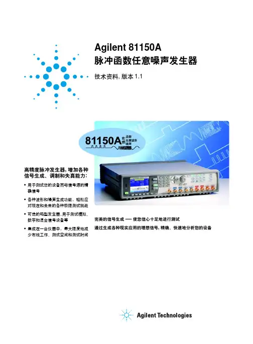
Choose your hardwareKey specificationsBandwidth 1 µHz - 120MHz (250 sine)Waveforms Noise, adjustable crest factor, sine, pulse, square, vamp, arbitrary waveform Channels1 or 2, differential outputsOutput Amplitude Amplifier High voltage: 50mV to +10V High bandwidth: 50mV to +5V Modulation types:AM, FM, PM, FSK, PWM external and internal Transition Times›2.5nsOutput Impedance 50 Ω/5 Ω selectable Sample rate 14-bit, 2G/s arbitrary waveform MemoryArbitrary: 512k points per channel Pattern: 16Mbit per channel Noise repetition rate 26 days Display Color, brightProgramming interfaces:LAN, SCPI 1992, IEEE 488.2 (GPIB), USB Supported driversAgilent VEE, IVI-COM, NI Labview, Matlab ®Standard, complete connectivity!LXI Class C compliantCouple/uncouple channels/channel addUSB 2.0AChannel 2: trigger out; Strobe out; Differential output Channel 1: trigger out; Strobe out; Differential outputTrigger mode Waveform ModeAdvanced mode (Modulation/Sweep/Bust)Keypad1.2.3.4.5.6.7.8.A 3-in-1 device for accelerated and accurate insight into your device• Create pulse, sine, square, ramp, noise and arbitrary waveforms to test your device - not the source • A 2 Channel version can be used either as 2 independent generators or as time synchronized coupled or added • Integrated in one instrument, which increases signal performance, minimizes cabling, space and test time• Glitch free change of timing parameters (delay, frequency, transition time, width, delay cycle). • Programming language compatible with Agilent 81101A, 81104A and 81110ATechnical data and pricing subject to change without notice. © Agilent Technologies, Inc. 2009, Printed in USA,May 5, 2009Pulse Pattern Generator Selection GuideLXI is the LAN-based successor to GPIB, providing faster, more efficient connectivity. Agilent is a founding member of the LXI consortium. Model Bandwidth Channels Voltage Price8114A 15MHz 1-ch 100V/2A Call 81101A 50MHz 1-ch 100mV - 10V Call 81104A + 81105A 80MHz 1 or 2 ch 100mV - 10V Call 81110A + 81111A 165MHz 1 or 2 ch 100mV - 10V Call 81110A + 81112A 330MHz 1 or 2 ch 100mV - 3,8V Call 81130A + 81131A 400MHz 1 or 2 ch 100mV - 3,8V Call 81130A + 81132A660MHz1 or2 ch100mV - 2,5VCallComplementary productsModelDescriptionDSO/MSO 6000, 7000InfiniiVision 7000 Series Oscilloscopes up to 1GHz bandwidthDSO/MSO 8604A Infiniium DSO/MSO Oscilloscope with 800MHz bandwidthDSO/MSO 5000InfiniiVision 5000 Series Oscilloscopes up to 500MHz bandwidthDSO 3000Economy DSO 3000 Series up to 200MHz bandwidth 32210A, 33220A, 33250AFunction generators with 10, 20 and 80MHz, 1 channelTypical ApplicationsFlexRay/CAN Physical Layer Receiver Test (Flyer: 5990-3160EN)Sensor Simulation Clock Signal Generation Radar Distance Testing Disc Drive TestsNoise and Jitter Source with Selectable Crest Factor Signal Source with Modulation Pulsed IV Measurements System Trigger SourceCapture & Reproduce Live SignalsRelated LiteraturePub Number Name5989-6433EN 81150A Pulse Function Arbitrary Noise Generator Data Sheet5980-0489E Pulse Pattern and Data Generators For Digital and Analog Testing5989-7860EN Agilent 81150A Pulse Function Arbitrary Noise Generator Applications5990-3233ENPCI Express® Revision 2.0 Receiver Testing with J-BERT N4903A and 81150A Pulse Function Arbitrary Noise Generator5989-9826ENAgilent 15431A Filter Set for 81150A 5989-9364ENAgilent 81150A Precision Digital NoiseCharacteristics on a Pulse Pattern ShapeAll parameters can be selected and edited with the Agilent Pulse Pattern GeneratorsDelay -timeWidthLo Hi Amp 0MATLAB is a U.S. registered trademark of the Math Works, Inc.PCI Express is a registered trademark of PCI-SIG.。

脉冲信号发生器使用方法信号发生器操作规程由于占空系数≤80%,所以在使用双脉冲或B脉冲输出时,应注意调整,使脉冲的延迟时间加上脉宽时间小于脉冲周期;在使用A 脉冲输出时,应使脉冲宽度小于脉冲周期由于占空系数≤80%,所以在使用双脉冲或B脉冲输出时,应注意调整,使脉冲的延迟时间加上脉宽时间小于脉冲周期;在使用A 脉冲输出时,应使脉冲宽度小于脉冲周期,否则将产生分频或无输显现象。
1、脉冲重复周期(频率)的调整调整范围为1μs~100ms(即重复频率为1MHz),共分1~10μs、10~100μs、100μs~1ms、1?10ms、10?100ms五挡,由周期波段开关实现粗调,由面板上方与之对应的电位器实现细调。
细调旋钮顺时针旋转时周期增大,顺时针旋转到底时,其周期值为高一挡的周期;细调旋钮逆时针旋转时周期减小,逆时针旋转到底时,其周期值为粗调挡刻度所指周期。
2、延迟时间的调整在部分仪器中,延迟时间是指B脉冲前沿相对A脉冲前沿的延迟时间。
调整范围为0.3?3000μs、共分0.3?3μs、3~30μs、30~300μs、300?3000μs四挡,分粗调、细调两种调整。
3、脉冲宽度的调整调整范围为0.1?1000μs、共分0.1?1ps、1?10|is、10?100ns、100?1000ns四挡。
也分粗调、细调两种调整。
A、B脉冲的宽度貌似相等,其相对误差≤±10%。
4、输出幅度及极性选择正、负脉冲由极性开关选择,从同一插孔输出,输出幅度的范围为150mV?20V。
衰减器以1、2、4、8、16倍衰减输出幅度。
幅度细调旋钮顺时针旋转时,幅度增大。
当衰减器置“1”、负载开关置“内”、幅度细调旋钮顺时针旋到底时,输出幅度最大为20V,误差≤±20%。
输出端具有50Ω内负载,也可外接负载,由负载开关选择。
5、脉冲选择输出脉冲有三种,即A脉冲(前脉冲)、B脉冲(后脉冲)、(A+B)脉冲(双脉冲),通过脉冲选择开关选择。
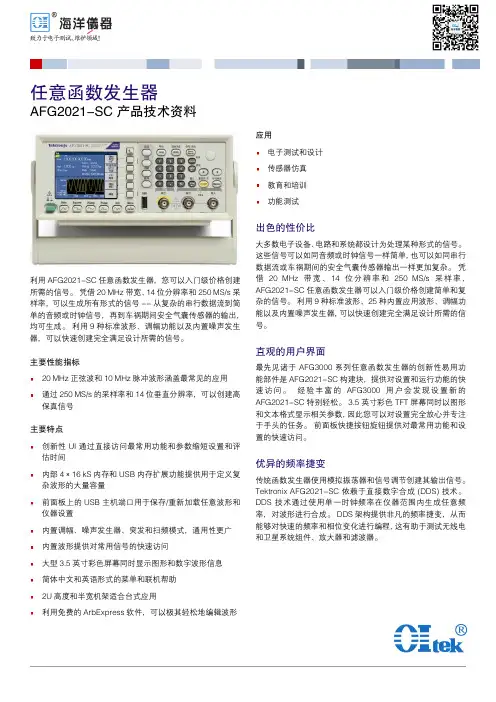
任意函数发生器AFG2021-SC产品技术资料利用 AFG2021-SC 任意函数发生器,您可以入门级价格创建所需的信号。
凭借 20 MHz 带宽、14 位分辨率和 250 MS/s 采样率,可以生成所有形式的信号 -- 从复杂的串行数据流到简单的音频或时钟信号,再到车祸期间安全气囊传感器的输出,均可生成。
利用 9 种标准波形、调幅功能以及内置噪声发生器,可以快速创建完全满足设计所需的信号。
主要性能指标20 MHz 正弦波和 10 MHz 脉冲波形涵盖最常见的应用通过 250 MS/s 的采样率和 14 位垂直分辨率,可以创建高保真信号主要特点创新性 UI 通过直接访问最常用功能和参数缩短设置和评估时间内部 4 × 16 kS 内存和 USB 内存扩展功能提供用于定义复杂波形的大量容量前面板上的 USB 主机端口用于保存/重新加载任意波形和仪器设置内置调幅、噪声发生器、突发和扫频模式,通用性更广内置波形提供对常用信号的快速访问大型 3.5 英寸彩色屏幕同时显示图形和数字波形信息简体中文和英语形式的菜单和联机帮助2U 高度和半宽机架适合台式应用利用免费的 ArbExpress 软件,可以极其轻松地编辑波形应用电子测试和设计传感器仿真教育和培训功能测试出色的性价比大多数电子设备、电路和系统都设计为处理某种形式的信号。
这些信号可以如同音频或时钟信号一样简单,也可以如同串行数据流或车祸期间的安全气囊传感器输出一样更加复杂。
凭借 20 MHz 带宽、14 位分辨率和 250 MS/s 采样率,AFG2021-SC 任意函数发生器可以入门级价格创建简单和复杂的信号。
利用 9 种标准波形、25 种内置应用波形、调幅功能以及内置噪声发生器,可以快速创建完全满足设计所需的信号。
直观的用户界面最先见诸于 AFG3000 系列任意函数发生器的创新性易用功能部件是 AFG2021-SC 构建块,提供对设置和运行功能的快速访问。
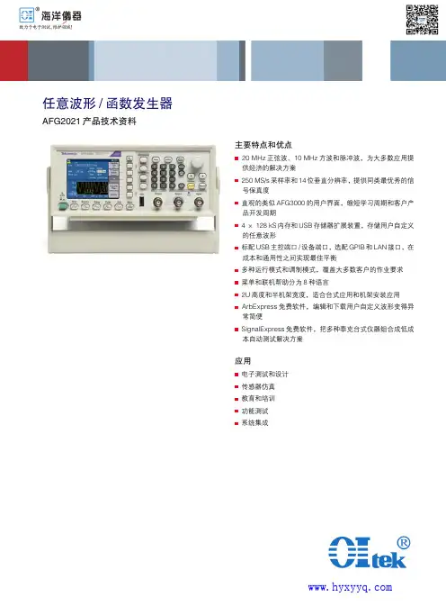
任意波形/函数发生器AFG2021产品技术资料主要特点和优点20 MHz正弦波、10 MHz方波和脉冲波,为大多数应用提供经济的解决方案250 MS/s采样率和14位垂直分辨率,提供同类最优秀的信号保真度直观的类似AFG3000的用户界面,缩短学习周期和客户产品开发周期4 × 128 kS内存和USB存储器扩展装置,存储用户自定义的任意波形标配USB主控端口/设备端口,选配GPIB和LAN接口,在成本和通用性之间实现最佳平衡多种运行模式和调制模式,覆盖大多数客户的作业要求菜单和联机帮助分为8种语言2U高度和半机架宽度,适合台式应用和机架安装应用ArbExpress免费软件,编辑和下载用户自定义波形变得异常简便SignalExpress免费软件,把多种泰克台式仪器组合成低成本自动测试解决方案应用电子测试和设计传感器仿真教育和培训功能测试系统集成产品技术资料2 杰出的性能,经济的价格目前几乎所有消费品都带有电路或器件,要求输入特定电子信号,以便产品正确运行。
这些信号既可以是简单的音频频率或时钟信号,也可以是比较复杂的信号,如碰撞过程中安全气囊传感器发出的串行数据流或信号。
由于提供了20 MHz 带宽、14位分辨率和250 MS/s 采样率,AFG2021任意函数发生器能够以入门级价格,生成简单的信号和复杂的信号。
由于其12种标准波形、调制功能和内置噪声发生器,您可以迅速创建所需信号,全面测试自己的设计。
传承AFG3000直观的用户界面AFG3000系列任意波形/函数发生器创新的简便易用特点首先体现在AF2021的构件上,其可以迅速进入设置和运行特性。
此外,AFG3000客户可以简便地迁移到新的AFG2021上,而不必学习新的用户界面。
3.5英寸彩色TFT 屏幕以图形格式和文本格式显示相关参数,简便地查看波形信息,用户可以对设置全面树立信心,把重点放在手边的任务上。
前面板上的快捷按钮和旋转旋钮可以用最少的工作和时间进入最常用的功能和设置。

一种脉冲波形可调的声音信号发生器设计周致【摘要】音频信号发生器是测量声音信号处理设备性能指标必不可少的仪器,文章首先论述了声音信号发生器的研究现状,然后针对现有技术存在的问题,提出一种可分别调节输出电压的占空比、频率、幅度的脉冲波形可调的声音信号发生器,且该声音信号发生器的占空比、频率、幅度可实现单一的调节。
最后针对设计的信号发生器进行了实验,实验结果表明文章提出并设计的新型脉冲波形可调的声音信号发生器实用且具有明显的优势。
%Audio signal generator is essential equipment to measure the sound signal and deal with equipment performance. The paper compendiously summarizes the overseas and domestic research status of voice signal generators. Then we put forward a new voice signal generator to solve the problems of existing technology, in which the duty ratio of output voltage, frequency, amplitude adjustable pulse waveform of the voice signal generator can be adjusted respectively, and the sound the duty ratio, frequency and amplitude of the signal generator can realize the single adjustment. The experimental results show that the proposed new type of pulse waveform with adjustable voice signal generator is practical and has obvious advantages.【期刊名称】《江苏科技信息》【年(卷),期】2016(000)009【总页数】3页(P70-72)【关键词】音频信号发生器;脉冲波形可调;设计【作者】周致【作者单位】山东科技大学电气与自动化工程学院,山东青岛 266590【正文语种】中文声音是人类表达思想、进行社会交流的主要载体。


·高电压及脉冲功率技术·紧凑型全固态高重复频率LC-Marx 脉冲发生器*庄龙宇, 杨均翔, 须貝太一, 江伟华(长冈技术科学大学 极限能量密度工学研究中心,新泻县 长冈市 940-2137)摘 要: 通过理论、模拟和实验对提出的全固态LC-Marx 发生器进行研究。
整个系统由一个MOSFET 开关和多个由一个磁芯制成的磁开关控制,该脉冲发生器直径为140 mm ,高为17 mm ,且随着级数的增加尺寸和重量基本不变。
运用谐振充电可以使电容充到源电压的1.82倍,五级LC-Marx 发生器用950 V 直流电压充电时,在500 Ω电阻上得到峰值电压为10.9 kV 、半高宽为400 ns 、上升时间为85 ns 、效率为30.43%的高压脉冲。
输出电压的上升前沿可以根据实际应用的要求,通过减小电容量缩短。
该脉冲发生器在频率低于30 kHz 下,可以持续稳定地运行。
该LC-Marx 脉冲发生器在气体放电中将具有较好的应用效果。
关键词: LC-Marx ; 脉冲发生器; 磁开关; MOSFET ; 谐振充电; 全固态; 高频率; 大气放电 中图分类号: TM836 文献标志码: A doi : 10.11884/HPLPB202133.210114Compact all-solid-state high frequency LC-Marx generatorbased on magnetic switchZhuang Longyu , Yang Junxiang , Sugai Taichi , Jiang Weihua(Extreme Energy-Density Research Institute , Nagaoka University of Technology , Niigata 940-2188, Japan )Abstract : An all-solid-state LC-Marx generator based on magnetic switch has been proposed and analyzed by theory, simulation and experiment. This system is controlled by 1 MOSFET and magnetic switches that are made by 1magnetic core. It has dimensions of 130 mm (diameter) and 60 mm (height), which almost not change with the stage increase. The capacitors could be charged to 1.82 times source voltage according to the principle of resonant charging.Five-stage LC-Marx generator could obtain a peak output voltage of −10.9 kV with rise time of 80 ns when the source voltage of 950 V is applied, and the energy efficiency is 30.43% on 500 Ω. The generator has been tested under 30 kHz that could work steadily. It could output higher voltage when used for atmospheric discharge.Key words : LC-Marx ; pulsed power generator ; magnetic switch ; MOSFET ; resonant charging ; all-solid-state ; high frequency ; atmospheric discharge近年来脉冲功率发生器在工业、国防和医疗等方面的应用要求向着固态紧凑化、高重频长寿命稳定运行和模块化等方向发展[1-4]。
Agilent Technologies8110A 150 MHz Pulse GeneratorTechnical SpecificationsFlexible pulses or patterns for digital designsKey Features · 150 MHz Timing· 2 ns Variable Transitions · 10 Vpp (20 Vpp) into 50 Ω · 10 ps Resolution· 0.1% Frequency Accuracy · 4 kbit Pattern per Channel · 3 and 4 Level Signals · 1 or 2 Output Channels· SCPI Programming Commands · Small Size· Graphic DisplayAgilent Technologies8110A 150 MHz Pulse GeneratorThe Agilent 8110A 150 MHz Pulse Generator is a test instrumentthat provides sufficient speed and performance for testing designs to their limits; testing under real-world conditions to verify the proper function of the design.· pulses, digital patterns andmultilevel waveforms for testing current logic technologies (CMOS, TTL, LVDS, ECL, etc.)· credible measurements · easy set-up and operation · upgrade capabilityReal World PulsesWith the pattern feature and the the optional second channel of the Agilent 8110A, real world s ignals, like reflections, distorted pulses, or three or even four-level signals can be simulated.Pattern Based TimingThe Agilent 8110A simulates all the clock and data signals needed to test digital designs. Conditions such as extended delays can be generated using pattern based timing features.Clean PulsesThe Agilent 8110A generates clean pulses with 10 psresolution, low jitter and good pulse performance across all operating temperatures orsettings. Parameters and trigger modes can be changed without generating unwanted pulses, so that reliable measurements are guaranteed.19812High AccuracyExcellent accuracy over a wide temperature range guarantees repeatable measurement results.Frequency accuracy, jitter,resolution and range can be enhanced further when the Agilent 8110A is used with the internal phase locked loop (PLL) of the Agilent 81106A as pulse period source.Delay CalibrationSystematic delays caused by cables,connections and adapters can be compensated when the Agilent81107A is installed. It offers enough additional delay range to compensate for 5 m of BNC cable.External Clock or Reference Frequency 1An external synthesizer or system clock can be used as clock source at the clock input of the Agilent 8110A to achieve the frequency accuracy and required. Thisfeature is ideal for simulating digital control signalssynchronously to the clock of the microprocessor.Up to 10 channels in parallel 2Up to 4 Agilent 8110As can be slaved to a master, so that 10synchronous channels can beprogrammed independently. With the Agilent 81107A multichannel deskew installed, the propagation delay of the set-up can becompensated, and all other output channels zeroed to the reference channel.Smooth Integration into Automated Test SystemsThe Agilent 8110A can be smoothly integrated into automated test systems, ensuring:·low integration costs ·low costs of ownershipAll Digital WaveformsThe waveform and triggerflexibility of the Agilent 8110A make it a universal digitalstimulus for any automated test sys-tem.Reliable MeasurementsAccuracy is specified over the whole temperature range that exists in a test rack. Setting check and built-in diagnostics allow you to monitor the correct operation of the Agilent8110A in an automated test system.Easy Rack IntegrationThe small size of the Agilent 8110A saves valuable rack space. Rear panel connectors and rack mount kits are optional.Reduced Programming InvestmentThe local user interface eases the transition from manual toautomated measurements and from the R&D bench toautomated manufacturing test. All parameters of the Agilent 8110A are programmable via GPIB. SCPI (Standard Commands for Programmable Instruments)facilitates the standardization of test programs.Low Cost of OwnershipThe proven hardware reliability of Agilent test and measurement prod-ucts results in high uptime of test systems and low maintenance costs.The Agilent 8110A offers a 3 year standard warranty.Easy Set-up and OperationView all timing parameters for both channels at a glance. Timing and level parameters can be entered in any format, e.g. period as frequency.The alternative graphic display shows the timing relationship of all pulse parameters on both channels graphically, making setting up the pulse generator easy - no extra oscilloscope is required.Pulses and patterns can be set up quickly using the convenient cursor keys, knob and data entry keys. You can even use the Autoset Key to resolve all timing conflicts.Memory CardSettings can be storedpermanently either internally or on the memory card for duplication in another test set-up.4Pattern ModePattern length:4 kbit/channel and strobe output.Output format:RZ (return to zero), NRZ (non-return to zero), DNRZ (delayed non-return to zero). Random pattern:PRBS 2^(n-1) n = 7,8,...,12Trigger ModesContinuous:continuous pulses, double pulses, bursts (single or double pulses) or patterns. External triggered:each active input transition (rising, falling or both) generates a single or double pulse, burst or pattern.External gated:the active input level (high or low) enables pulses, double pulses, bursts or patterns. The last single/double pulse, burst or pattern is alwayscompleted.External width:the pulse shapecan be recovered. Period and width ofan external input signal is main-tained. Delay, levels and transitionscan be set.Manual:simulates an external inputsignal.Internal triggered (only with Agilent81106A):internal PLL replaces anexternal trigger source. Pulses, doublepulses, bursts or patterns can be set.Inputs and OutputsExternal inputused for trigger, gate or externalwidth.Input impedance:50 Ω /10 kΩ selec-table.Threshold:- 10 V to + 10 V.Max. input voltage:± 15 Vpp.Sensitivity:≤300 mVpp typical.Transitions:< 100 ns.Frequency:dc to 150 MHzMin. pulsewidth:3.3 ns.Strobe output and trigger outputLevel:TTL or ECL selectable.Output impedance:50 Ω typical.Strobe output: user-defined, 16 kbit pat-tern (NRZ) when in pattern mode.Max. external voltage:- 2 V/+7 V.Transition times:2 ns typical.Pattern:4096 bits NRZ in patternmode.Delay from external input to strobeoutput:in pattern mode same as fortrigger output.Trigger OutputLevel:TTL or ECL selectableOutput impedance:50 ΩtypicalTrigger pulse width:typically 50% ofperiodMaximum external voltage:-2 V/+7 VTransition times:2 ns typicalDelay from external input to triggeroutput:l8.5 ns typicalAgilent 81107A Multichannel Deskew for the Agilent 8110ACan be retrofitted without recalibration. Supports twooutput channels. Themultichannel deskew can be used for two applications:Up to 10 channels:compensates delay between external input and trigger outputs when using up to five8110As synchronously.Delay calibration:compensates for measurement system delays or pre-trigger delays of oscilloscopes. Variable range:0 ns to 28 ns Additional fixed delay:6.5 ns typical Resolution:10 ps User InterfaceOverprogramming:all parameters canbe overprogrammed(exceeding specifications) to fullyexploit the hardware limits.Setting check:warning messages indi-cate potentially conflicting parame-ters due to inaccuracy.Error messages indicateconflicting parameters.Help key:displays a context-sensitive message.Autoset key:resolves all timing con-flicts.Non-volatile memory:currentsetting is saved on power-down.Up to nine user settings and one fixeddefault setting can be stored in theinstrument.Clear memory:clears all nine user set-tings.Memory card:320 settings can bestored on a 1 MB PCMCIA card(MS-DOS ).Remote ControlOperates according to IEEEstandard 488.2, 1987 and SCPI1992.0.Function Code:SH1, AH1, T6, L4, SR1,RL1, PP0, DC1, DT1, C0.Programming times:all checks anddisplay off.GeneralOperating temperature:0°C to +55°C.Storage temperature:-40°C to +70°C.Humidity:95% r.h. up to 40°C ambi-ent temperature.EMC:conforms to EN50082-1,EN 55011, Class A.Noise emission:5.7 bel typical.Battery:Lithium CR2477-N.Safety:IEC1010, CSA1010.Power requirements:100-240 Vac, ± 10%, 50-60 Hz;100-120 Vac, ± 10%, 400 Hz.Power consumption:300 VA max.Max. dimensions (H * W * D):89 mm * 426 mm * 521 mm.Weight: 9.2 kg net, 13.8 kgshipping.Recalibration period:one year recommended.Warranty:three years standard.6Ordering Information - 8110AT he minimum order must include the 8110A mainframe and one 81103A output channel. A second output channel, the 81106A PLL/external clock or the 81107A multichannel deskew are optional. All configurations are available from the factory. Alternatively, additional modules can be ordered later and fitted by the user or an Agilent service facility.Qty per Mainframe Categorymin max Description NumberMainframe[1]1150 MHz Pulse Generator Mainframe Agilent 8110AModules1210 V/2 ns Output Channel Agilent 81103A01PLL/External Clock Agilent 81106A01Multichannel Deskew Agilent 81107AAll options are orderable with the mainframes.AccessoriesOpt UN2Rear Panel ConnectorsOpt 1CP Rack Mount and Handle Kit (5062-3975)Opt 1CN Handle Kit (5062-3988)Opt 1CM Rack Mount Kit (5062-3974)Opt 1CR Rack Slide Kit (1494-0060)Opt UFJ 1 MB SRAM Memory CardAgilent 15104A Pulse Adder/SplitterLanguage optionsOpt ABD German Localization (08110-91112)Opt ABF French Localization (08110-91212)Opt ABZ Italian Localization (08110-91312)Opt ABE Spanish Localization (08110-91412)Opt ABJ Japanese Localization (08110-91512)Opt AB0Chinese Localization (08110-91612)Additional documentation optionsOpt 0B2 Additional English Operating Manual(08110-91012)Opt 0BW Service Manual (08110-91021)08110-91031Service Documentation (Component Level)Support OptionsOpt 1BP MIL Std. 45662A Calibration with Test DataOpt W32 3 Year Customer Return Calibration CoverageOpt W34 3 Year MIL Calibration ServiceOpt W50 5 Year Customer Return Repair CoverageOpt W52 5 Year Customer Return Calibration CoverageOpt W54 5 Year MIL Calibration Service7Related Agilent Literature·Agilent Family of Pulse/PatternGenerators, brochure, p/n 5980-0489EAgilent Technologies'Test and Measurement Support, Services, and AssistanceAgilent Technologies aims to maximize the value you receive, while minimizing your risk and problems. We strive to ensure that you get the test and measurement capabilities you paid for and obtain the support you need. Our extensive support resources and services can help you choose the right Agilent products for your applications and apply them successfully. Every instrument and system we sell has a global warranty. Support is available for at least five years beyond the production life of the product.Two concepts underlay Agilent's overall support policy: "Our Promise" and "Your Advantage."Our PromiseOur Promise means your Agilent test andmeasurement equipment will meet its advertised performance and functionality. When you are choosing new equipment, we will help you with product information, including realistic performance specifications and practical recommendations from experienced testengineers. When you use Agilent equipment, we can verify that it works properly, help with product operation, and provide basic measure-ment assistance for the use of specifiedcapabilities, at no extra cost upon request. Many self-help tools are available.Your AdvantageYour Advantage means that Agilent offers a wide range of additional expert test and measurement services, which you can purchase according to your unique technical and business needs. Solve problems efficiently and gain a competitive edge by contracting with us for calibration, extra-cost upgrades, out-of-warranty repairs, and on-site education and training, as well as design, system integration, project management, and other professional services. Experienced Agilent engineers and technicians worldwide can help you maximize your productivity, optimize the return on investment of your Agilent instruments and systems, and obtain dependablemeasurement accuracy for the life of those products.By internet, phone, or fax, get assistance with all your test & measurement needs Online assistance:/find/assist Phone or Fax United States:(tel)180****4844Canada:(tel)187****4414(fax) (905) 206 4120Europe:(tel) (31 20) 547 2000Japan:(tel) (81) 426 56 7832(fax) (81) 426 56 7840Latin America:(tel) (305) 267 4245(fax) (305) 267 4286Australia:(tel) 1 800 629 485 (fax) (61 3) 9272 0749New Zealand:(tel) 0 800 738 378 (fax) 64 4 495 8950Asia Pacific:(tel) (852) 3197 7777(fax) (852) 2506 9284Product specifications and descriptions in this document subject to change without notice.Copyright © 2000 Agilent Technologies Printed in Germany 10/20005980-1212EFor more information, please visit us :/find/pulse_generator。
基金颁发部门:总装备部;基金名称:弹道加速度测试与控制研究基金编号:武器装备预研基金项目(51405020305BQ0110);基金申请人:刘明杰基于C8051F单片机信号发生器设计与应用The Design and Application of the Signal Generator Based on C8051F(北京理工大学)王世虎刘明杰李晓峰WANG Shi-hu LIU Ming-jie LI Xiao-feng摘要:信号发生器设计以C8051F121单片机为核心,采用串口通信和D/A转换,通过在VB 可视化操作界面下参数化调节信号的幅值、脉宽、频率、持续时间,可以得到任意波形。
数据通过串口传给单片机,单片机经过锁存器将数据保存在外部存储器中,通过控制电路启动D/A转换产生模拟信号。
然后可以作为弹加速度测试装置的输入信号,来验证实际弹侵彻的过载曲线。
关键词:信号发生器 ;C8051F;DAC;外部扩展存储器中国分类号:TP368.1 文献标识码:BAbstract: Signal generator designed based on C8051F121 microcontroller, using serial communication and D / A converter, can achieve arbitrary waveform through the VB operation interface by parametrically conditioning the signal amplitude, pulse width, frequency and duration. The data which is transmitted to MCU through the serial port, is stored in external memory through the data latch, and then the MCU activates the D/A converters to produce analog signals by the control circuits. The analog signal can be then used as input signal of projectile acceleration testing device to verify the actual penetration of the deceleration-time curves of projectile.Key words: signal generator; C8051F; DAC; external extended memory1 引言在实际的弹道加速度测试中,需要产生许多波形曲线用来验证,而能够产生任意波形的信号发生器价格昂贵,不适合工程实际的需求,通过设计产生的信号发生装置,不仅成本低,而且功能强大,可以产生满足各种需要的信号。