
《可焊性测试》课件
- 格式:pptx
- 大小:3.06 MB
- 文档页数:26

第33卷第7期 Vol-33 No.7 企业技术开发 TECHNOLOGICAL DEVELOPMENT OF ENTERPRISE 2014年3月 Mal".2014
元器件可焊性测试技术研究
李承虎,邹文忠
(中国电子科技集团公司第38研究所,安徽合肥230031)
摘要:元器件引脚可焊性直接关系到焊点可靠性和产品长期可靠性。文章通过对元器件引脚可焊性测试方案选择、测 试技术研究及应用,及时评估元器件在焊接前的可焊性状况,为后期焊接过程中形成高质量焊点奠定重要基础。 关键词:可焊性;焊点;可靠性 中图分类号:TN710 文献标识码:A 文章编号:1006—8937(2014)07—0038—02
Testing technical research of solderability of component
LI Cheng-hu,ZOU Wen-zhong
(No.38 Research Institute of CETC,Hefei,Anhui 23003 1,China)
Abstract:The solderability of the components pin is directly related to the reliability of solder joint and long-term reliability of
product.Based on the selection of solderability testing scheme of the components pin,the research and application of test technology, the weldability of components before welding is effectively evaluated in this paper,laying impo ̄ant basis for high quality welds of
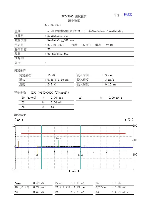
PASS评价 : SAT-5100 测试报告
测定数据
驱动
文件组
数据文件
测定日
样品名称
焊锡
助焊剂
备考May 26,2021
: e:\可焊性检测报告\2021.5\5.26\NewDataGrp\NewDataGrp
: NewDataGrp.swg
: NewDataGrp_001.swm
: May 26,2021 气温 26.2℃ 湿度 59.0%
: TS
: 96.5Sn3Ag0.5Cu
: :
测定条件
测定量程
形状
温度: 10 mN
: 0.46 x 0.30 mm
: 245 ℃浸入时间
浸入速度
浸入深度: 5 sec
: 3 mm/s: 0.10 mm
评价参数 (IPC J-STD-002C [G](setB))
T0 (t1-t0) F2 F5 ≦
≧
≧2.00 sec
0.00 mN
F2 AA ≧0.00 mN s
测定结果
123456710
0
-100100200300( ( mN mN mN ))
( ( sec sec sec ))( ( ℃ ℃ ℃ ))
Fendt1
t2Fmax
Fmax T0 (t1-t0)
F2 : 0.43 mN: 0.24 sec
: 0.32 mNFend T1 (t2-t1)
F5 : 0.41 mN: 1.43 sec
: 0.41 mNSb 2/3Fmax
AA : 0.95 : 0.28 mN
: 1.64 mN s

_表面安装技术 一一//一 一
可焊性、焊接能力
和焊点可靠性之评估和测试
马学辉 (汕头超声印制板公司,广东汕头 5I5065)
摘 要 文章主要在于明确可焊性、焊接能力和焊点可靠性三者之间的联系和区别,指出对它们进行评估和测试时 其各自关注的主要特性和常见的评估和测试方法,同时简单介绍影响它们的关键因素。 关键词 可焊性;焊接能力:焊点可靠性 中图分类号:TG44 文献标识码:A 文章编号:1 009—0096(2007 J 07—0060—04
The Evaluation and Test of Solderability,
Soldering Ability and Solder Joints Reliability
Ma Xuehui
Abstract The objective of the article is to clearly describe the relation and diference among solderability,
soldering ability and solder joints reliability and point out the corresponding characteristics when evaluating and testing these items.Usual evaluating and testing methods are briefly introduced and the critical factors to the items are also briefly discussed. Key words solderability;soldering ability;solder joints reliability
《)前言
可焊性和可靠性是电子组装行业经常提到的名 词。焊接能力则很少有人提起。有人往往会把焊接

品 质 保 证 指 导 书
文件名称 可焊性测试作业指导书 页 码 1 OF 3
文件编号 PZ-WI013 发行版本 A
发行日期 2004-4-15 修订版次 1
深圳市信恳实业有限公司福永分公司
1.0目的:
指导IQC检查员对来料进行可焊性测试。
2.0适用范围:
需做可焊性测试的来料。
3.0参考文件
无
4.0 使用工具:
小锡炉、显微镜(放大镜)、焊料:Sn63Pb37、助焊剂
5.0定义
镀层电极组件:电极由多层金属电镀而成的组件.如贴片电阻、贴片电容、贴片电感等。
引线电极贴片组件:电极由金属引线成型为自动贴片的组件。如贴片二极管、贴片IC等。
引线电极插机元件:电极由金属引线成型为自插或手插的组件。如编带电阻,散装插机电容。
6.0测试方法
6.1镀层电极组件,引线电极贴片组件的可焊性测试。
6.1.1用镊子取出无脏污待测组件,作松香笔涂敷电极。
6.1.2电极朝下侧立组件。
6.1.3将电极浸入230±5℃小锡炉4±1秒。引线电极贴片组件锡面距组件体约0.7mm,镀
层电极组件锡面距锡约0.2mm。
6.1.4取出组件5秒后,用放大镜(显微镜)观察电极上锡是否良好。
6.2引线电极插机组件。
6.2.1取出引线无脏污组件,用松香笔涂敷电极。
6.2.2将电极垂直浸入230±5℃小锡沪4±1秒,锡面距组件体2±1mm。
6.2.3 取出组件5秒后,放大镜(显微镜)观察电极上锡是否良好。
7.0上锡判定
90%上浸锡部份上锡良好,无针孔。浸锡边缘与电极面涧焊。
拟制: 陆伟 审批: