埋地GRP管施工措施(中英)2
- 格式:pdf
- 大小:477.21 KB
- 文档页数:13

无砟轨道基准网(GRP)测设施工工法无砟轨道基准网(GRP)测设施工工法一、前言无砟轨道基准网(GRP)测设施工工法是一种用于确定地铁或高铁无砟轨道几何和坐标的工程测量方法。
该工法通过采集车体行驶轨迹的数据,结合数学和测量原理,能够精确计算出无砟轨道的几何参数和坐标信息,为轨道施工提供准确的数据支持。
二、工法特点1. 高精度:该工法利用先进的测量仪器和数据处理技术,可以达到毫米级的高精度测量。
2. 高效率:相比传统测量方法,无砟轨道基准网(GRP)测设施工工法具有快速测量、数据处理自动化的特点,能够提高施工效率。
3. 灵活性:该工法适用于不同类型和规模的施工项目,并且可以根据实际情况进行灵活调整和改进。
4. 安全可靠:采用先进的测量仪器和安全措施,确保施工过程中的安全性和数据的可靠性。
三、适应范围无砟轨道基准网(GRP)测设施工工法适用于地铁、高铁等无砟轨道的施工工程,可以用于新建轨道线路的测量、调整和改进,也可以应用于现有轨道线路的维修和改造工作。
四、工艺原理该工法利用车体行驶轨迹的测量数据,通过数学模型和测量原理,计算出轨道的几何参数和坐标信息。
具体的工艺原理包括以下几个方面:1. 测量仪器准备:准备高精度的测量仪器,包括全站仪、导轨板等。
2. 数据采集:通过安装在车体上的传感器和测量仪器,采集车体行驶轨迹的数据。
3. 数据处理:通过计算与数据处理软件,将采集的数据进行清理、去噪、滤波和校正,获得准确的轨道几何参数和坐标信息。
4. 合格判定:通过与设计要求进行比较,判定测量结果是否符合要求,如果不符合要求,则进行进一步调整和改进。
五、施工工艺1. 测量仪器准备:准备好全站仪、导轨板等测量设备,并进行校准和调试。
2. 数据采集:安装传感器和测量仪器在车辆上,通过车载计算机和数据采集软件进行数据采集。
3. 数据处理:将采集到的数据传输到计算机中,通过数据处理软件进行清理和校正,得到准确的轨道几何参数和坐标信息。
Method StatementDocument Title:Document Number:Document no.:Revision HistoryEXW-P011-0000-CM-CHE-MT-00027 Protection of Existing UtilitiesSection CONTENTSPage1.0 Purpose of Protection of Existing Utilities 32.0 Scope of Protection of Existing Utilities 33.04.0 Reference:Definitions:335.0 Personnel & Responsibilities 46.0 Permits and Licences 57.0 Resources to be used for Protection of Existing Utilities 58.0 Detailed method of carrying out this method statement 69.0 Quality Control and Requirements 1010.0 Health & Safety Considerations 611.0 Environmental Considerations 1112.0 Appendices 14Appendix A - Risk Assessment 14Appendix B - Tool Box Talk 18Appendix C - Inspection and Test Plan 19Appendix D - Checklist Form 21Section 1.0: Purpose of Protection of Existing UtilitiesThe purpose of this Method Statement is to outline the procedures and techniques which are to be adopted in protection of existing utilities which is to be carried out in P011 project area.Section 2.0: Scope of Protection of Existing UtilitiesThis scope covered in this method statement is to outline the methodology for execution of all works related to the Construction of the Protection of Existing Utilities. This statement shall cover all the trenches for Power Supply (EHV/HV, MV and LV etc.) Works, Potable Waters, Irrigation(TSE) and Fire Water Lines, (Storm Water Drainage Pipes, Station Sewage Lines, Q-Tel works etc.), ITS and SSD, including setting out, excavation, installation of protection slab, backfilling, compaction and reinstatement etc. This method statement does not include the spilt duct protection for existing electricity cable crossing the road.Section 3.0: Reference:Work carried out and testing performed under this Section of the Specification shall comply with the requirements of the following Standards to the extent that they are relevant and not overridden by the Specification.•Qatar Construction Specification Section 8,Part 2(QCS2010) and Section 20, Part4(QCS2010).•Project specification.•Project Quality Plan Doc. No.EXW-P011-0000-CM-CHE-PQ-00001-Rev.CE•Shop drawings.•Kahramaa Water and Electricity General Specification•Kahramaa Regulations for Clearances and works in the vicinity of Extra-High Voltage installations•Project Health & Safety Plan – EXW-P011-0000-HS-CHE-PL-00048;•Construction Environmental Management Plan – EXW-P011-0000-YE-CHE-PL-00071;Section 4.0: Definitions:Client : ASHGHALProject Manager : KBRSupervision Consultant : HalcrowContractor : China Harbour Engineer Company Limited (CHEC)QCR : Quality Control RecordITP : Inspection and Test PlanJSA : Job Safety AnalysisRA : Risk AssessmentHSE : Health, Safety and EnvironmentP.S : Project SpecificationSection 5.0: Personnel and ResponsibilitiesPlease refer to the following table for manpower:The work of Protection of Existing Utilities will be carried out by CHEC, headed by the Construction manager.•Construction Manager–responsible for the construction work coordination and arrangement of civil works, in charge of site engineer. To get under control HSE requirements as well as QA/QC.•HSE Engineer/Safety Officer–responsible for HSE on site during construction, coordinate with Site Engineer. Coordinate Tool Box meetings and improve the content. Stop any unsafe act/work and report immediately to the HSE manager & construct manager.•QC Engineer– responsible for quality of structure on site during construction, coordinate with Site Engineer.•Surveyor– responsible for survey work and settlement monitoring work on site, coordinate with Site Engineer.•Site Engineer –Site engineer responsible for site demolition and clearance work, coordinate with HSE Engineer, QA/QC engineer, surveyor, will in charge of foremen, operators,•Construction Superintendent / Foreman-directly supervises the work activity on the site and has full control over the use of the labour, plant and equipment. He ensures that the work is carried out in full compliance with the specification, and in a manner that conforms to the safety requirements. He reports to the Site Engineer when the work is complete and ready for inspection.•All personnel (operators) involved in lifting, confined space, drilling, welding, construction plant and equipment etc, should be qualified and the relevant certificate should be available.•Quality Control Inspector-Ensure that all activities that are required to be inspected in the construction have been inspected and approved. Accompany the company representative while carrying out inspections and release hold points. Issue NCR’s when and where required and ensure that construction provides the appropriate corrective and preventive action.Section 6.0: Permits and LicencesWork permit shall be provided and a copy shall be kept on site. Where required as per project contract specification, permits & licences shall be obtain from relevant authorities prior to start with the related works or activities.Section 7.0: Resources to be used for Protection of Existing Utilities7.1 Technical InformationReferences:•Qatar Construction Specification Section 8,Part 2(QCS2010) and Section 20, Part4(QCS2010).•Project Specification.•Method statement of engineering survey: CHEC-CEC-MT-001-0.•Method statement of soil filling and compaction for road works: EXW-P011-0000-CM-CHE-MT-00011.•CHEC’S HSE Plan & Quality Plan.7.2 EquipmentPlease refer to the following table for equipments:Section 8.0: Detailed method of carrying out this method statement8.1 Preparation Works•An overall project schedule developed shall include the sequence of civil works, necessary equipment, tools and procedure for various civil works activities.•Prior to commencement of work all materials, resources, Personnel Protective Equipment (PPE) and necessary equipment and tools shall be set in place.•Approved written procedures, material approvals and necessary inspection request forms shall be made available before start of work.•Only skilled personal will be deployed for carrying the protection of live existing utilities.•Prior to start any works make sure that approved SIS (service information sheet) is available.•Before excavation commence, the area to be excavated should be carefully marked out and then, where appropriate, by the use of cable location device the position of each cable in the vicinity should be determined as far as possible.•Scanning and trial holes shall be done prior to commencement of trench excavation.•Coordinate with Kahramaa supervisor and other End Users for necessary inspections.•Make sure that a supervisor and safety officer from contractor available full time at site.•Information on the position and depth of cables in the proposed work area should be recorded on plan by those responsible for the works so that it can be readily understood by the supervisors and works carrying out the work at site.8.2 Sequence for Undertaking Protection of Existing UtilitiesDiagram 8.1 Sequence for Undertaking Protection of Existing Utilities8.3 Surface Cleaning.After preparation work has been completed, Contractor shall clean the surface of the existing ground. Any existing unsuitable material shall be removed.8.4 Jobsite BarricadeThe jobsite shall be barricaded with required material/device in proper way with appropriate signage. All the safety measures shall be checked and approved by HSE department with written record before commencement.8.5 Survey Setting OutBefore beginning trench excavations, the route of the pipeline shall be surveyed and set out accurately and the existing ground level shall be agreed with the Engineer. The relevant information shall pass to in-charge site engineer and foreman with written record.8.6 Mark out the Lines.The centreline and the edge of the trench shall be marked out in site as shown on the drawings.Complete full scanning for area with cable detector and mark utilities direction. Besides, trench excavation shall be carried out by such methods and to such lines, dimensions, and depths as shall allow for the proper construction of the Works.8.7 Excavation.The structure of the road and the typical section for existing utilities protection are show in the following drawing.TYPICAL SECTION FOR EXISTING UTILITIES PROTECTION(A-A)Based on the soil conditions, the excavation shall be 500 mm from existing ground level mostly by machinery and some finishing works shall be done manually.•The excavated material shall be disposed to designated location with care.•Trench excavation width according to type of existing Utilities, as per approved shop drawings.•Where trenches are excavated open cut in roads, the asphalt shall be saw cut along the edges of the trench, prior to excavation.•In the lanes of the road that remain open to traffic, road drains and channels shall be kept free from construction materials, debris and obstruction at all times.•The Engineer may direct the trench excavation to be realigned from that shown on the Drawings to facilitate the flow of traffic.•Any excavation carried out by the Contractor to prevent slips and fall, or should portions of trench walls slip or fall away, the Contractor shall at his own expense take all necessary remedial measures including the excavation removal and reinstatement of all the ground thereby disturbed.8.8 Installation of Reinforced Concrete Slabs:•Protection slab would be pre-cast and shall comply with the requirements of relevant•Precast Protection slab will be transported to the site by trailers and stored in a designated area in the vicinity of where they are to be installed.•After excavation of 500 mm from existing ground level, the excavated area need to be compacted and leveling.•The area around the utilities shall not to be disturbed.•Concrete provided as a protection to pipes shall be Grade C20, placed to the required depth in one operation.•The reinforcing steel bar and the concrete shall comply with the relevant specification8.9 Backfilling and Compaction•The backfilling shall be (2 Layers) done by layers of which maximum loose (uncompact) thickness shall not exceed 150mm the layer markings shall be in place in order to control the loose thickness.•Approved material is to be used for backfilling;•Marking tape to be installed after the first layer of backfilling the trench.•The material shall be watered and compacted to achieve the required dry density;•Fill material shall be compacted not less than 95% dry density.•For more details review the attached drawing .•Backfilling shall, wherever practicable, be undertaken immediately the specified operations preceding it have been completed. Backfilling shall not, however, be commenced until the parts of the Works to be covered have achieved a strength sufficient to withstand all loading imposed thereon.•Backfilling around existing structures shall be undertaken in such manner as to avoid uneven loading or damage.•Where the excavations have been supported and the supports are to be removed, these, where practicable, shall be withdrawn progressively as backfilling proceeds in such a manner as to minimise the danger of collapse. All voids formed behind the supports shall be carefully filled and compacted8.10 Install SignboardCHEC shall install some signboard near the excavation area. Marker Posts will then be installed as required by approved drawings.Section 9.0: Quality Control and Requirements•All workers shall be adequately experienced•All relative documentation such as method of statement , quality procedures etc. shall be available at work location.•All sites shall be visited and inspected in detail.•All inspection shall be as per approved project ITPs/QCPs.•The Contractor shall provide the necessary testing apparatus for monitoring soil properties and shall maintain the apparatus in good order. A daily log of test carried out shall be provided to the Engineer. Testing of soil properties shall be carried out by an approval laboratory.•The Contractor shall ensure that the material laid immediately next to a structure, concrete wall or thrust block is well compacted as per specification.Section 10.0: Health & Safety Considerations10.1 General safety issues∙Staffs should wear full set of PPE (Helmet + Safety Shoe + Reflective vest + Eye Goggle) and fire fire extinguisher, first aid kit, ear plugs, communication devices, warning signals, safety tapes, lighting for illumination, red flusher, green flusher as minimum requirement while on the site. The workers should wear additional PPE when performing specific task as per safety rules and regulations of the project.∙Operator must have valid certificate for proper equipment operation.∙Operator must maintain daily equipments complying with operation requirement.∙Barriers were arranged to separate the work place.∙Regular safety checks will be performed to eliminate potential hazards and to conform to safety regulations.∙The safety precautions should meet the requirements of QCS2010.∙Safety shall follow and ensure that there shall not be any damage to the existing live underground services while excavation of cable trench.10.2 Emergency ArrangementAll injuries, serious incidents and property damages shall be reported to Safety Officer and the client’s resident site representative as soon as possible while client’s incident reporting process will be followed.Death / Serious Bodily Injury / Crisis∙The Project Manager/ Site Agent / Safety, Health & Environmental Manager / Safety Officer / relevant Government Departments (E.g. Labour Department or Police, etc.)will be verbally informed immediately.∙The Safety Officer will submit a report in prescribed format to the Labour Department and the SOR within 7 days of an accident.∙The HSE Manager will submit a Comprehensive Accident Investigation Report within 7 days of an accident.Loss Time Injury∙The Project Manager/ Safety, Health & Environmental Manager / Safety Officer / will be informed as soon as practicable.∙The HSE Manager will submit a Comprehensive Accident Investigation Report to the SOR within 7 days of an accident.Serious Property Damage / Significant Near Miss∙The Project Manager / Safety, Health & Environmental Manager / SOR will be informed as soon as practicable.∙The Safety Officer will submit a Comprehensive Accident Investigation Report within 7 days of an accident.Dangerous Occurrence∙The Project Manager / Safety, Health & Environmental Manager / SOR will be informed as soon as practicable.∙The Safety Officer will submit a report in prescribed format within 24 hours.∙The Safety Officer will submit a Comprehensive Accident Investigation Report within 7 days of the incident.10.3 Consents and Permits∙8.3.1 Emergency contact should be informed to all staff before the work as stated in HSE Plan. The contact numbers of the ERT (Emergency Response Team) are posted at vicinity on site and site offices and main rest areas. Key contact numbers are:∙shall inform their supervisors or the Safety Officer or any member of the Emergency Team or site management as quickly as possible.∙The location should be cordoned off and persons not involved with the recovery action are not allowed to enter the area.∙After confirming that the emergency is over and there is no more danger, the Emergency Team Commander or the Project Manager shall give instructions to resume work and all employees shall return to their work places.10.4 Consents and Permits∙10.4.1 Obtain excavation permit-to-work from HSE dept prior to excavation works.∙10.4.2 The work place should be checked by the engineer before working. Any high-risk areas or the carrying out of high-risk operations such as hot work or confined space, etc.Permit-to-work system will be implemented.Section 11.0: Environmental Considerations11.1 Environmental Aspects∙The leakage of the equipment might occur. Leakage prevention, e.g. drip tray, should be provided for Leakage incidents.∙The vehicles and equipment might produce a large amount of dust. Dust control, e.g. water spraying, should be implemented at site.∙The vehicles and equipment might produce a lot of noise during construction. Noise pollution should be concerned.11.2 Housekeeping∙The site shall always be kept in clean condition, rubbish and waste materials shall be frequently and regularly removed off site.∙Adequate number of rubbish collectors or designated area shall be provided for waste disposal.∙Materials shall be stacked safely and securely.∙Plant, equipment and material shall be positioned, as far as possible, not to cause obstruction to site accesses.Section 12.0: Appendices AAppendix B: Tool Box Talk (TBT)Method Statement for Protection of Existing Utilities. Page 19Method Statement for Protection of Existing Utilities. Page 20Appendix D: Checklist FormDrawing Ref.O.M.C. (%):Date:。
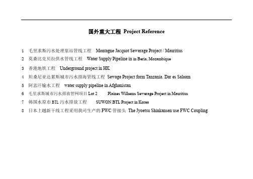
国外重大工程Project Reference1 毛里求斯污水处理泵站管线工程Montagne Jacquot Sewerage Project / Mauritius2 莫桑比克贝拉供水管线工程Water Supply Pipeline in in Beria, Mozambique3 香港地铁工程Underground project in HK4 坦桑尼亚达累斯城市污水排海管线工程Sewage Project form Tanzania. Dar es Salaam5 阿富汗输水工程water supply pipeline in Afghanistan6 毛里求斯城市污水排放管网项目Lot 2 Plaines Wilhems Sewerage Project in Mauritius7 韩国水原市BTL污水排放工程SUWON BTL Project in Korea8日本上越新干线工程采用我司生产的FWC管接头The Jyoetsu Shinkansen use FWC Coupling毛里球斯污水处理泵站管线工程此项目是由毛里球斯公共事业部于2003年10月22日通过面向国际招标方式,经过严格的,符合FIDIC 条款的评审程序,于2005年元月7日与中国水利电力对外公司正式签署合同。
本项目业主为公共事业部污水局(WMA ),出资方为日本协力基金(JBIC ),咨询工程公司为NJS-SERV ANSINGH JADA V PARTNERS CONSULTING ENGINEERS LTD ,主承包商为中国水利电力对外公司(CWE );工程合同额为2300余万美元,于2005年3月1号正式开工。
合同范围为:两个污水泵站,及一个污水处理厂;工程范围涉及到土建,工艺设备,电气,自动控制等。
其中GRP 管道采用中国浙江东方集团HOBAS 离心管道产品,最大管道直径为1200MM ,产品质量得到业主和咨询认可和好评。

埋地钢管施工方案1. 引言本文档旨在提供一种埋地钢管施工方案,该方案适用于道路、管道、桥梁等工程中的管线敷设。
本方案主要包括施工准备、施工工序、安全措施等内容,以确保施工的安全、高效进行。
2. 施工准备在进入施工阶段前,需要进行以下准备工作:2.1. 设计方案确认确认施工所需的设计方案,包括埋设深度、埋设角度、管道布局等,确保施工过程符合设计要求。
2.2. 施工材料准备准备好所需的施工材料,包括钢管、橡胶垫片、螺栓、焊接材料等。
材料应具备相应的质量认证及合格证书。
2.3. 施工设备准备准备好所需的施工设备,包括挖掘机、起重机、焊接设备等。
设备应进行必要的检修和维护,确保其正常运转。
3. 施工工序埋地钢管施工主要包括以下工序:3.1. 施工现场布置在施工现场设置必要的安全警示标志,并划定施工区域。
同时,要确保施工区域周边无其他工程施工或交通阻碍。
3.2. 地表开挖根据设计方案,在地表开挖出适当的沟槽,用于埋设钢管。
开挖深度和宽度应符合设计要求,同时注意地下管线的避免。
3.3. 钢管安装将准备好的钢管进行安装,按照设计要求逐段铺设,并通过螺栓、焊接等方式进行连接。
在每段连接处使用橡胶垫片密封,确保连接处不会渗漏。
3.4. 固定和保护在钢管铺设完成后,用适当的固定措施固定钢管,并进行保护。
针对特殊情况,如道路施工,可以采用混凝土保护层等方式,确保钢管不受外力损坏。
3.5. 现场清理和整理施工完成后,对现场进行清理和整理,清除施工垃圾及占用的道路材料,恢复道路交通秩序。
4. 安全措施在埋地钢管施工过程中,需要采取以下安全措施:4.1. 安全防护施工现场需设置必要的安全防护措施,如设置警示标志牌、警戒线,并提醒工作人员注意施工设备的运行。
4.2. 人员培训对施工人员进行必要的培训,确保其熟悉施工工艺和安全要求,并配备必要的安全装备。
4.3. 施工设备检修定期检修施工设备,确保其正常运转。
同时,要确保设备的操作人员具备相应的资质和技能。
(施工方案)埋地管道施工方案与技术措施(可以直接使用,可编辑优秀版资料,欢迎下载)农田林网1 施工工艺流程定位放线→沟槽开挖→沟槽支撑→室外埋地管道基础→室外管道安装→管道下管与配管→管道支墩→管道检验与试压→沟槽的回填土→验收2 施工方法及要点1)定位放线按照设计施工图的坐标位置确定管道中心线位置,用龙门板在地面固定,并且分别测出各龙门板中心点的标高,作为开槽、配管的依据,龙门板要妥善保护,间隔距离一般不超过10米。
同时管线中心桩和水准点均应用平移法设置与管线施工范围外的便于观察和使用的部位.2)沟槽开挖a.当管道的测量定位线经复核无误后,即可进行沟槽开挖。
沟槽开挖采用机械,局部较小的部位可采用人力。
b。
沟槽开挖后,应分段分别挖好集水坑,用污水泵排除沟槽内集水。
c。
开挖管沟沟底最小宽度注:1。
表中d为管外径.2.当沟槽设有支撑时,沟深在2米以内,沟底宽度增加0。
1米;深度在3米内,沟底宽度增加0。
2米;3.用机械开挖沟槽时,其沟槽宽度按挖土机械的切削尺寸而定,但不小于本表规定数值。
3)沟槽的支撑当沟槽开挖较深、土质不好或受场地限制开梯形槽有困难而开直槽时,加支撑是保证施工安全的必要措施。
支撑形式根据土质、地下水、沟深等条件确定常分为横板一般支撑、立板支撑和打桩支撑等形式,其适用条件可参见下表:注意事项:①撑板与沟壁必须贴紧,立木垂直,撑杠要平直.立木要排列整齐,便于拆撑。
②木撑杠部要用扒钉钉牢,金属撑杠下部要钉托木,两端同时旋紧,上下杠松紧一致。
在土质良好时一般可随填随拆,如有塌方危险地段可先回土,再起出支撑。
4)室外埋地管道基础a.天然地基:土壤耐压强度较高,地下水位较低,(如干燥黏土、砂质黏土等。
)将天然地基整平,管道敷设在未经扰动的原土上.b.混凝土基础;管基为回填土时,设混凝土基础。
c.给水铸铁管、镀锌钢管在一般情况下,可不做基础,将天然地基整平,管道铺设在未经扰动的原土上.c。
加筋UPVC塑料排水管,宜设置混凝土条形基础。
UNDERGROUND PIPING INSTALLATION 地下管道的安装1.0 SCOPE 范围This Specification, accompanied by other applicable specifications, drawings and details, covers the requirements for field handling, storage, fabrication and installation of ferrous metallic and non-metallic underground piping systems.Wherever a difference exists between this specification and the drawings, the drawing shall govern. No deviation shall be made from this specification without written approval from ***l. In principle handling, storing and installations shall be in accordance with manufacturers instructions. This specification shall be used in conjunction with the "Combined Underground and Paving Plan", herein after called CUPP, and a package, containing standardized details, General Notes and References. 本规范,及其他适用的规范、图纸和详细资料,涵盖了铁质金属和非金属地下管道的现场搬移、储存、预制和安装的要求。
仓库混凝土地坪施工方案Construction method of warehouse concrete flooring 1.根据设计要求和现场实行的大流水作业的实际情况,地坪的施工流水段划分According to design requirement and construction condition, flooring area will be divided into pieces for casting concrete 。
2.每个流水段的施工流程如下:The construction procedure are following:1)场地平整,夯实。
Backfilling soil and compaction.2)级配碎石夯实。
Crushed stones compaction.3)混凝土垫层。
Concrete cushion.4)防潮层。
Damp-proof layer。
5)焊接钢筋笼与桩的锚固钢筋,绑扎底板钢筋;Welding re-bar of pile caps, re-bar work of flooring slab.6)立模板;Install formwork.7)安装控制标高的槽钢;Install level controlling steel channel.8)浇C30地坪混凝土;Cast concrete of floor slab C30 with SIKAFLOOR -2 SYNTOP-1 surface.9)机械磨光;Flooring smoothing10)养护。
Curing concrete.3.主要的施工方法介绍:Construction method:1)水平标高的控制:大面积地坪的施工成功与否,水平标高的控制是十分重要的一个环节,根据以往厂房地坪的施工,我们都采用事先抄平固定槽钢的办法取得了较好的效果,具体做法如下图所示:Controlling flooring level: In large area concrete floor slab construction, level controlling is one of the most important point. According to constructing experience, level control by steel channel is a good way. Detail drawing are following:4:浇捣砼的要求:Requirement for casting concrete:①、每次浇捣砼前,事先与砼站联系好,并且听天气预报,防止在浇捣过程中下雨等不利因素都要考虑到筹划好。
Aabove—ground conduit(pipeline) 地上管道accessible duct 通行地沟acrylonitrile butadiene stryene pipe ABS工程塑料管(ABS) active earth pressure 主动土压力adaptor slab 井筒盖板aerial crossing structure 跨越结构air—tight test 气密性试验anchor 固定墩arriving shaft 终端工作坑asbestos—cement pipe (ACP)石棉水泥管BBackfill 回填土bearing pressure distribution diagram 地基反力图形bedding angle 基础(座)中心角bend 弯管bending test 弯曲试验beveled pipe 斜口管Boussinecq pressure bulb布氏压力图形box(rectangular) conduit 矩形管道breadth of conduit 管道宽度breadth of trench 槽宽buried conduit(pepeline) 埋地管道buttand strap joint 抹带接头Ccable duct 电缆沟cap 盖堵casting place collar joint 现浇套环接头casting place joint 现浇接头(缝)cast—in—place(situ) conduit 现浇管道cast iron pipe(CIP) 铸铁管caulking填料;捻缝cement mortar lining 水泥砂浆内衬cement mortar with steel mesh strap joint 抹带接头centrifugal process 离心法chamber井室;检查室chemically pre-stressed concrete pipe 自应力混凝土管circular conduit 园形管道coating涂层coefficient of vertical earth pressure 竖向土压力系数collar type joint 套管(筒)式接头combined drainage conduit(pipeline) 合流管道combined duct 综合管道;共同沟compaction around the pipe with relatively untamped above thetop of pipe 中松侧实法compaction the two sides of pipe 胸腔夯实compansator 补偿器composite crossing 组合跨越composite pipe 复合管concrete cradle 混凝土管基(管座)concrete pipe(CP) 混凝土管conduit 管道conduit section 管道截面continuous casting process 连续浇铸法cooling water pipeline 冷却水管道core vibrated casting process 芯模震捣法core winding process 管芯缠丝法corrosion prevetive of pipes 管道防腐corrugated pipe 波纹管coupling of bousing 卡箍式管接头cover slab 井筒盖板crack width calculation 裂度宽度验算cracking load under three edge bearing test 裂缝荷载crown 顶点culvert 涵洞DD—load D荷载法dead’loadon conduit (pipeline) 管道恒荷载design pressure 设计压力detachable type joint 活接头dewatering 降水distribution of elastic reaction 弹性反力图形double junction 四通downpipe 雨落管downspout 雨落管duckfoot 肘管管托duct 管道ductile castiron pipe(DIP) 可延性铸铁管dynamic water pressure 动水作用力EEarth cover(heightofsoil) over con-duit 覆土高度earth pressure at rest 静止土压力earth pressure on embankment con/duit 上埋式土压力earthpressure on trench conduit 沟埋式土压力earthpressure under soil arch 土拱压力effective length of pipe 管有效长度elastic installation pipeline method 弹性敷管法elastic reaction of soil 土的弹性抗力elbow 弯头electrical conduits 电工套管elliptical conduit 椭园形管道embedded type PCCP(PCCP—E) 埋置式预应力钢筒混凝土管embedded—cylinder pipe(ECP) 埋置式预应力钢筒混凝土管expansion bellows 波纹补偿器expansion bend 弯管补偿器expansion joint 伸缩接头expansion joint 伸缩节expansion loop 弯管补偿器exterior prism 管侧土柱FFiber glass reinforced pipe(FRP) 玻璃纤维管filament winding process 纤维缠绕法finely divided solid transmission pipeline 细颗粒固体输送管道fixed support 固定管托;固定支座fixed trestle 固定支架flange 法兰flanged joint 法兰接头flat subgrade 素土平基flattening test 压偏试验;偏平试验flexible joint 柔性接头flexble pipe 柔性管flexible rubber expansion joint 可曲挠橡胶接头flexible trestle 柔性支架flexural stiffness ratio 刚柔比four—point loading test 四点法荷载试验free—flow conduit(pipeline) 自流管道fusion joint 热溶接头Ggastrans mission pipeline 输气管道gasket ring 密封圈glass fibrere inforced plastics pipe(GRP) 玻璃纤维增强热固性塑料管gravity—flow conduit(pipeline) 重力流管道gray cast iron pipe(CIP) 灰口铸铁管gully grating sand frames 雨水篦gully trap 雨水井Hhanger 吊杆haunches under pipe 管下腋角beaped load 堆积荷载heat—supply pipeline 供热管道heating pipeline 采暖管道height of conduit 管道高度horizontal earth pressure 水平土压力horses hoe conduit 马蹄形管道hydrostatic pressure 静水压力hydrostatic proof test 水压检验试验Iimpact factor 动力系数impact test 冲击试验industrial pipe line 工业管道inner sleeve joint 内套环接头inside diameter 内径inspection chamber 检查井interior prism 管上土柱intermediate jacking station 中继间invert 底点JJacking pressure 顶力Joint angular deflection 接头角位移Joint axial deformation 接头轴向位移Joint deflection test 接头角位移试验Joint packing 接头密封料Ioint sealant 接头密封料Joint straight draw test 接头拉伸试验LLag factor 滞后系数Lateral earth pressure 侧向土压力Leading pipe 导管Leak test 严密性试验lined type PCCP(PCCP—L) 内衬式预应力钢筒混凝土管lined—cylinder pipe(LCP) 内衬式预应力钢筒混凝土管liner 内衬live load on conduit(pipeline) 管道活荷载load on conduit(pipeline) 管道荷载loading distribution diagram 荷载分布图形longitudinal calculation 纵向计算MManhole 检查井manhole cover and flames 检查井盖manhole steps 踏步max. temperature difference between construction and operation 闭合温差mean diameter 平均直径mechanical joint 机械接头mixed structure conduit 混合结构管道Nnatural(original) ground surface 原状(始)地面natural soil 原状土new austrian tunnelling method 新奥法nodular cast iron pipe 球墨铸铁管non—pressure conduit(pipeline) 无压管道norminal diameter(DN) 公称直径OOffset 乙字管Olander’s bulbform distribution 奥兰特分布图形oriented(guiding) trestle 导向支架outer sleeve joint 套环接头outlet 出水口outside diameter 外径oval conduit 椭园形管道over excavation 超挖overhead prpeline 架空管道ovoid conduit 卵形管道Ppartial fixed trestle 半固定支架passive earth pressure 被动土压力petroleum transmission pipeline 输油管道pipe accesory 管道附件pipe bridge 管桥pipe casing slip joint 套筒式伸缩器pipe clip 管卡;管箍pipe crossing 管道跨越pipe diameter 管直径pipe duct 管沟pipefitting 管件pipe in pipe 双层管pipe jacking method 顶管法pipe length 管长pipe roofing method 管棚法pipe support 管托;管道支座pipeline 管道pipeline(conduit)structure 管道结构pipeline eaerial(over) crossing 管道跨越pipeline appurtenance 管道附属构筑物pipeline for waste water(sewerage) in building 建筑排水管道pipeline for water supply in building 建筑给水管道pipeline joint 管道接头pipeline pier 管道支礅pipeline trestle 管道支架pipeline undercrossing 管道穿越plastic sandwich pipe 发泡塑料管polybutylene pipe(PB) 聚丁烯塑料管polyethylene pipe(PE) 聚乙烯塑料管polypropylene pipe(PP) 聚丙烯塑料管precast fabricated conduit 预制装配管道pressure class 压力等级pressure conduit(pipeline) 压力管道prestressed concrete cylinder pipe(PCCP) 预应力钢筒混凝土管prestressed concrete pipe(PCP) 预应力混凝土管profile(ribbed) wall plastic pipe 异型(肋型)塑料管protective cased pipe 保护套管push—on type joint 插入式接头Rrare earth cast iron pipe 稀土铸铁管reaction wall 反力墙rebated pipe 企口管reception pit 接收工作坑red mud plastic anti—weather pipe 红泥聚氯乙烯耐候塑料管reducer 异径管;渐缩管reducerslab 缩颈盖板reinforced concrete pipe(RCP) 钢筋混凝土管reinforced plastic mortar pipe(RPMP) 增强塑料砂浆管reinforced thermo setting resin pipe(RTRP) 增强热固性树脂管rigid joint 刚性接头rigid pipe 刚性管rigid trestle 刚性支架riseofarch conduit 拱沟矢高road(street)gully 雨水口roller support 滚动管托;滚动支座roller suspension process 悬辊法Ssand box casting process 砂型浇铸法sealing gasket 密封圈self—anchoring joint 自锚式接头self—prestressed concrete pipe 自应力混凝土管semi—elliptical conduit 半椭园形管道semi—flexible pipe 半柔性管semi—rigid pipe 半刚性管separate foundation 分离式基础service ebility pressure 工作压力sewage conduit(pipeline) 污水管道shaft 井筒shaped by injection molding 注模成型法shaped by screw rod extruder 挤出成型法shapped subgrade 土弧基础shield tunneling method 盾构法single junction 三通sinking pipeline method 沉管法施工site load 施工荷载site pressure test 现场水压试验sleeve connection 杯口连接sleeve expansion joint 松套伸缩接头sleeve joint 套管(筒)式接头slider support 滑动管托;滑动支座slip—on coupling 活箍socket(bell) and spigot joint 承插式接头socket pipe 承口管soi1improvement 地基处理soil treatment 地基处理solvent cement joint 粘接接头splayed end pipe 斜口管spreading angle 分布角spring hanger 弹簧吊杆spring line 侧点stability calculation 稳定验算stainless steel pipe 不锈钢管starting shaft 起始工作坑stee lpipe 钢管stiffness calculation 刚度验算stiffness calss 刚度等级stiffness ring 刚性环stiffness test 刚度试验storm sewer conduit(pipeline) 雨水管道straight butt(plain) end pipe 平口管strength calculation 强度计算structural crossing 结构跨越subaqueous pipeline 水下管道submarine pipeline 海底管道submerged pipeline 水下管道support feet 肘管管托surcharge load 堆积荷载surface laver 涂层surge pressure 波动压力sustained pressure test 持续压力试验Ttable vibrated casting process 振动台震捣法thermal insulation of pipes 管道隔热;管道保温thickness of conduit structure 管道结构厚度thickness of pipe wall 管壁厚threaded joint 螺纹接头three—edge bearing test 三支承法试验three—point loading test 三点法荷载试验thrust blocks 止推墩thrust pit 顶进工作坑thrust wall 止推墙tongue and groove joint 企口式接头tongue and groove pipe 企口管traffic load 车辆荷载transversal calculation 横向计算trench depth 槽深trench installation 开槽施工;沟槽敷设trench less installation 不开槽施工tunneling method installation 隧道法敷设two—edge bearing test 双支承法试验tyre pressure 轮压Uultimate load under three—edge bearing test 破坏荷载unannealed nodular(ductile)cast iron pipe 铸态球墨铸铁管unback filled trench 末回填沟槽under—ground conduit(pipeline) 地下管道undisturbed earth 未扰动土unpassable duct 不通行地沟unplasticised polyvinyl chloride pipe(UPVC管) 硬聚氯乙烯塑料管Vvacuum pressure 真空压力ventilating duct 通风管道vertical compressed casting process 径向挤压法;立式挤压法vertical earth pressure 坚向土压力;垂直土压力vertical vibrated casting process 立式振捣法vitrified clay pipe 陶土管Wwall pipe chase 穿墙套管water distribution pipeline 配水管道water removal 排水water supply conduit(pipeline) 给水管道water tight test 闭(灌)水实验water transmission conduit(pipeline) 输水管道welding joint 焊接接头wheel pressure 轮压working pressure 工作压力works hydrostatic test 水压检验试验。
天然气工程项目部液化天然气(LNG)站线项目地下管道GRP管道安装施工技术方案编制:施工技术审核:安全管理审核:质量管理审核:审定:批准:目录1 适用范围 (1)2 工程概况 (1)3 编制依据 (1)4 施工准备及要求 (1)5 施工程序 (2)6 施工技术要求 (2)6.1材料检验 (2)6.2沟槽开挖、回填及管道基础施工 (2)6.3 GRP管道安装 (4)7 系统压力试验 (7)8 质量控制措施 (7)9 安全技术要求 (8)10 人力资源需求与施工计划 (10)11 施工机具需求计划 (10)附表2: (14)1 适用范围本施工方案适用于海南液化天然气(LNG)站线项目工艺厂工程由中石化第十建设有限公司(STCC)所负责的地下给排水管道海水管线(SW)系统。
2 工程概况地下管道各系统管线技术质量参数及工程量详见下表:3 编制依据1、《给水排水管道工程施工及验收规范》 GB50268-20082、《工业金属管道工程施工及验收规范》 GB50235-20103、《石油化工建设工程施工安全技术质量规范》 GB50484-20084、《钢质管道聚乙烯胶粘带防腐层技术质量标准》 SY/T0414-20075、中国五环工程有限公司设计说明及施工图纸6、新核玻璃钢管道安装指导手册4 施工准备及要求4.1施工按设计文件和相关规范、标准要求,根据建设单位提供的施工界域内地下管线、(建)筑物资料、工程水文地质资料等,深入现场,掌握现场实际情况,做好施工准备。
4.2施工单位负责熟悉和审查施工图纸,掌握设计意图与要求,实行自审、会审(交底)和签证制度,发现图纸中的问题并及时向监理和业主提出意见和建议。
4.3临时水准点、管道轴线控制桩、高程桩,必须经过复测方可使用,并应经常校核。
4.4建设单位应向施工单位提供施工影响范围内的地下管线(构筑物)及其他公共设施资料。
施工单位对既有管道、构(建)筑物与拟建工程衔接的平面位置和高程,开工前必须校测,并应采取措施加以保护。
CONTENTS目录1 Scope 范围2 References And Applicable Codes 参考文件3 Method statement 施工措施4 Construction Quality Records And Inspection Reports施工质量记录和检查报告5 Revision Note 修订注释Appendix Joint Lubricant Requirements附录涂抹接头润滑油用量1 Scope范围This procedure shall apply to excavating, back-filling, material handlingStorage, transportation, installation, pressure testing and flushing of GRP pipe in Nanhai HDPE/PP plant.本程序适用于南海石化项目PP+HDPE装置GRP管道的管沟开挖回填、管材现场装卸保管倒运、安装、试验、冲洗的施工。
2 References And Applicable Codes参考文件2.1 NH-HDPE+PP-QCPR-322 Procedure for Dimensional Control尺寸控制程序2.2 NH-HDPE+PP-WPR-211 Procedure for Hydrostatic Testing and Flushing of Piping管道水压试验及冲洗程序2.3 NH-HDPE+PP-WPR-206 Procedure For Excavation & Backfilling土方开挖及回填施工程序2.4 NH- HDPE+PP-PR-242 Method statement in rainy season雨季施工措施2.5 SP-8310-0000-0026 Materials & workmanship specification permanent UG work 地下施工材料及技术要求2.7 Code for construction and acceptance of water supply and sewerage pipelines. GB50268 – 97 给水排水管道工程施工及验收规范2.8 Guide of Specifications for Installation of Underground GRP PipeLZF-0623-01-03 地下GRP管安装手册5.2 测量放线、管沟开挖Setting-out and Trench excavationGeneral requirements for setting-out and trench excavation refer to NH-HDPE+PP-WPR-206 Procedure For Excavation & Backfilling. The trench figure as follow:测量放线、管沟开挖一般施工要求见NH-HDPE+PP-WPR-206土方开挖及回填施工程序,管沟图如下:Figure 4.2 TrenchDimension “A” (see Figure 4.2) must alw ays be wide enough to allow for adequate space to ensure proper placement of backfill in the haunch region and to operate compaction and excavate equipment. Bottom width of pipe trench shall be twice the pipe diameter plus 600mm, but in any case not less than 1.0meter.图4.2中A的尺寸必须满足开挖回填机械和人工作业的要求,管沟底宽一般为管直径加600,但不少于1.0M。
When raining during construction and water level rising, the solution refers to NH- HDPE+PP-PR-242 Method statement in rainy season. 施工时遇上雨天及高水位时,处理要求见NH- HDPE+PP-PR-242雨季施工措施.。
5.3 Pipe BeddingAfter excavation, a sand bag should be laid at the bottom in every 4 meter, and the net height of bag should be 100 mm. Excavating a little deeper at the joint of pipe, and the thickness of pipe bed cannot be less than 50mm.Filling with sands &water and compacting as specified when backfilling. 在管沟挖好后,底部每根管每隔4米放一个沙袋,压管后沙袋净高100mm,管子的接头处挖深一些,管床的厚度不能低于50 mm,回填时按规定充沙放水密实。
Figure 4.5Proper bedding supportFigure 4.6Improper bedding support5.5 管道安装Piping InstallationThe laying of pipes shall be in the order of main pipe first, and then branch; large pipe first, and then small pipe to ensure the accuracy of coordinate of the joint with outside. Surveying shall be performed to confirm the location of placement of all pipe-fittings, both at installation and later, when backfilling reaches the middle of the pipe.管子按先主管后支管、先大管后小管的顺序铺设,确保与外界相连点的坐标的准确性。
安装时和回填至管子中部时都需进行测量,以确认所有管件的安放位置。
5.5.1 Joining Pipes 管道连接5.5.1.1 Double "O" rings with locking key 带锁的双O型环连接。
The jointing method to be used for the GRP Pipe system is a combination of GRP butt/strap joint and doubl e “O” ring bell and spigot joint as shown below.这种连接方式使用在GRP管承插接头上,双O型环承插连接形式如下:Figure 3.1-2Ring l and spigot locking jointA准备Preparationa) Ensure that the outside diameter of the spigot end of the pipe is thoroughly cleaned and free of any dust, sand, grit etc.承插管接头必须十分干净,没有灰尘、沙砾等b) Inspect the two 'o' rings to be installed on the spigot ends of the pipes. Check to ensure the 'o' rings are completely free of any damage and have been thoroughly cleaned. 检查承插头上的两个O型环,O型环必须完整、干净没有受到任何伤害c) Place the rings in the 'o' ring grooves ensuring that the ring is uniformly stretched along its entire length and not twisted in any way (see Figure 3.2). The quickest and simplest method of doing this is to place the first 'o' ring in the groove nearest the pipe end, subsequently rolling the second 'o' ring into the second groove.把O型环放置在槽里,确保紧贴沟槽和没有扭曲(如图3.2)。
又快又简单的办法是先把第一个O型环放在离管端最近的槽里,然后把第二个O型环滚进第二个槽里。
d) Ensure that the two pipes being joined are level, so that the spigot will fit concentrically into the bell. Two plugs are supplied fitted to the bell for joint testing. Each pipe should be installed so that one of the two plugs on the bell is on top of the pipe.确保对接的两管段水平,这样易于组装。
安上杯口上接头试验用的两个堵头,其中一个必须向上。
e) Thoroughly coat the 'o' rings and inside surface of the bell with the lubricant provided. O型环上及杯口内涂上润滑油f) Using soft-slings and chain-blocks, anchor one pipe segment to the support slab to prevent accidental movement. 使用软吊索或倒链锚固一根管子,以防随意移动Figure3.2Balancing the tension in rubber 'o' ring, which also ensure the ring is not twisted.B组对Alignmenta) The pipes should be brought together using two daisy chains.用两个倒链对拉把两段组对在一起b)The spigot should not be pushed home until it touches the end of the bell section. A (1-3)mm gap is required here to accommodate the tolerances for insertion of the locking chord.承插头不要插到底,予留1-3 mm间隙调整锁孔偏差。