YD8410 立体声音大功率双模数字功放IC
- 格式:pdf
- 大小:2.07 MB
- 文档页数:11
数字功放及其在测量时的注意事项江苏省电子信息产品质量监督检验研究院史锡亭数字功放即脉冲调制的D类功放,与模拟功放的主要差别在于前者功放管处于开关工作状态。
在数字功放出现以前,音频功率放大器最常用的为AB类功放,AB类功放保留了B类功放效率高的优点,同时由于使用小偏置电流而能实现较小的交越失真,在重放正弦波时理想效率高于70%。
因为实际重放的声信号有很大的动态范围,如AM收音、磁带能达到50dB,FM收音、CD远超过此值,从而导致模拟音频功放实际效率很低,功放级需要较大的散热片,限制了其在对散热及效率较高要求场合的使用。
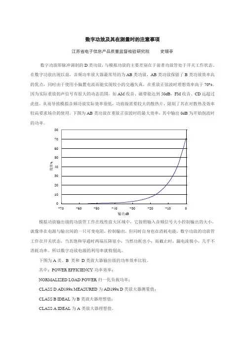
下图为AB类功放在重放正弦波时的最大效率,其中输出0dB为开始削波时就像串在电源与输出间的一只可变电阻,控制输出,但同时自身也在消耗电能。
数字功放的功放管工作在开关状态,当其饱和导通时两端压降很小,当然功耗也小;而截止时,漏电流极小,几乎不消耗功率。
所以数字功放电源的利用率就特别高。
下图为A类、B 类和D类放大器输出级的功率效率比较。
其中:POWER EFFICIENCY功率效率;NORMALIZED LOAD POWER归一化负载功率;CLASS D AD199x MEASURED为AD199x D类放大器测量值;CLASS B IDEAL为B类放大器理想值;CLASS A IDEAL为A类放大器理想值。
输出功率和效率的差异在中等功率水平处很大。
这对于音频很重要,因为大音量音乐的长期平均功率水平要比达到P max的瞬时峰值水平低很多(为其1/5到1/20,取决于音乐类型)。
对于音频功放,若认为PLOAD = 0.1 PLOADmax是一个合理的平均功率水平,按照这个功率水平评估D 类功放输出级的功耗是B类功放输出级的1/9,是A类功放输出级的1/107。
调制技术如下图所示,其一为脉宽调制技术,即将音频信号转换为PWM数字音频信号,PWM信号的占空比与原音频信号的瞬时值相关,占空比50%表示音频信号瞬时值为0;另一种脉冲调制技术被称为脉冲密度调制技术(PDM),脉冲密度大的地方,表示电压高;稀的地方,电压就低。
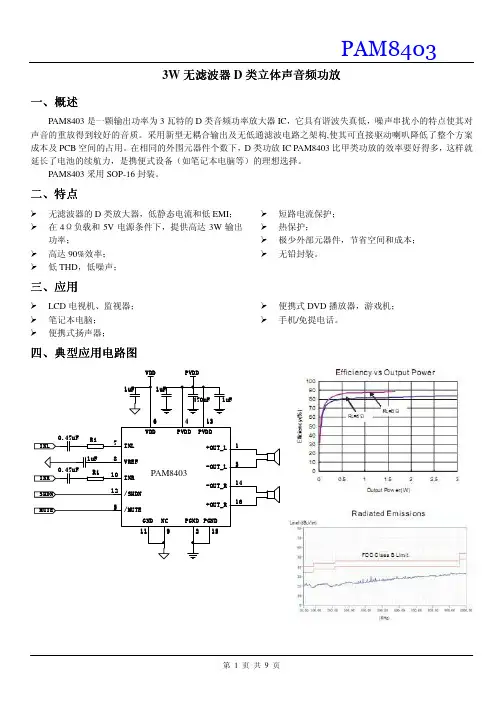
MOS电路CS38172 15W免滤波低EMI立体声D类音频功率放大电路本资料适用范围:CS3817EO 1、概述CS3817EO是一款15W(每声道)立体声高效D类音频功率放大电路。
先进的EMI 抑制技术使得在输出端口采用廉价的铁氧体磁珠滤波器就可以满足EMC要求。
内部包括一个直流检测电路来对扬声器进行保护,直流检测电路在输入电容损坏或者输入短路时关断输出级。
CS3817EO可以驱动低至4Ω负载的立体声扬声器,具有高达90%的效率,使得在播放音乐时不需要额外的散热器。
CS3817EO应用于LCD电视、消费类音频设备。
其特点如下:● 15W/声道的功率输出(16V电压,8Ω负载,TND+N等于10%)● 10W/声道的功率输出(13V电压,8Ω负载,TND+N等于10%)● 30W的功率输出(16V电源,4Ω单声道负载,TND+N等于10%)● 效率高达90%,无需散热片● 较大的电源电压范围6.5V~20V● 免滤波功能,输出不需要电感进行滤波。
● 输出管脚方便布线布局● 良好短路保护和具备自动恢复功能的温度保护● 良好的失真和防噗声功能● 内置增益26dB● 差分输入● 具有静音和待机功能● 简单的外围设计● 封装形式:HTSSOP282、功能框图与引脚说明2. 1、功能框图2. 2、功能描述音频信号进入以后,经过脉宽调制模块,完成音频信号对载波信号的调制,此模块由Error AMP、比较器等部分组成。
比较器将积分后的信号与三角波信号进行比较,这一步出来的信号已经是PWM信号了。
输出管驱动电路完成PWM波对输出开关管的驱动。
相关的模块还有电平转换模块,通过自举升压产生上管的驱动栅压;输出部分还设有短路检测电路,当所接负载过小导致电流过大时,启动保护机制关闭电路。
其他模块还有输出管栅压电源模块,产生栅驱动电压;低压电源模块,产生基准电压;电压确认模块,完成AVDD确认、GVDD确认和AVCC确认三个功能;三角波产生模块,负责产生PWM编码用的三角波;偏置和基准模块,负责产生各模块所需的偏置电流;温度检测模块,负责监测芯片温度;控制逻辑,完成上电或启动时复位并消除冲击声,温度和短路保护等。
UC-8410 Hardware User’s ManualFirst Edition, October 2008/product© 2008 Moxa Inc. All rights reserved.Reproduction without permission is prohibited.UC-8410 Hardware User’s ManualThe hardware described in this manual is furnished under a license agreement and may be used only inaccordance with the terms of that agreement.Copyright NoticeCopyright © 2008 Moxa Inc.All rights reserved.Reproduction without permission is prohibited.TrademarksMOXA is a registered trademark of Moxa Inc.All other trademarks or registered marks in this manual belong to their respective manufacturers.DisclaimerInformation in this document is subject to change without notice and does not represent a commitment on the part of Moxa.Moxa provides this document “as is,” without warranty of any kind, either expressed or implied, including, but not limited to, its particular purpose. Moxa reserves the right to make improvements and/or changes to this manual, or to the products and/or the programs described in this manual, at any time.Information provided in this manual is intended to be accurate and reliable. However, Moxa assumes no responsibility for its use, or for any infringements on the rights of third parties that may result from its use.This product might include unintentional technical or typographical errors. Changes are periodically made to the information herein to correct such errors, and these changes are incorporated into new editions of the publication.Technical Support Contact Information/supportMoxa Americas:Toll-free: 1-888-669-2872 Tel: +1-714-528-6777 Fax: +1-714-528-6778 Moxa China (Shanghai office): Toll-free: 800-820-5036 Tel: +86-21-5258-9955 Fax: +86-10-6872-3958Moxa Europe:Tel: +49-89-3 70 03 99-0 Fax: +49-89-3 70 03 99-99 Moxa Asia-Pacific:Tel: +886-2-8919-1230 Fax: +886-2-8919-1231Table of ContentsChapter 1Introduction..................................................................................................1-1 Overview..................................................................................................................................1-2Package Checklist....................................................................................................................1-2Product Features......................................................................................................................1-2Product Hardware Specifications.............................................................................................1-3 Chapter 2Appearance and Dimensions......................................................................2-1 Appearance..............................................................................................................................2-2Dimensions..............................................................................................................................2-3Hardware Block Diagrams.......................................................................................................2-4LED Indicators.........................................................................................................................2-4Reset Button.............................................................................................................................2-5Real Time Clock......................................................................................................................2-5 Chapter 3Mounting Options........................................................................................3-1 Wall or Cabinet Mounting........................................................................................................3-2DIN-Rail Mounting..................................................................................................................3-3 Chapter 4Hardware Connection Description.............................................................4-1 Wiring Requirements...............................................................................................................4-2Connecting the Power..............................................................................................................4-2Grounding the UC-8410..........................................................................................................4-3Connecting to the Network......................................................................................................4-3Connecting to a Serial Device..................................................................................................4-4Connecting to the Console Port...............................................................................................4-4CompactFlash..........................................................................................................................4-6USB..........................................................................................................................................4-7DI/DO......................................................................................................................................4-7 Appendix A Regulatory Approval Statements..............................................................A-11IntroductionThank you for purchasing the Moxa UC-8410 RISC-based ready-to-run embedded computer.The UC-8410 features 8 RS-232/422/485 serial ports, 3 10/100 Mbps Ethernet ports, 4 digital input and 4 digital output channels, and CompactFlash and USB ports for adding additional memory. All of these features make the UC-8410 ideal for your embedded applications.This manual introduces the hardware of the UC-8410 embedded computers. After a brief introduction of the hardware features, we focus on installing and configuring the hardware.The following topics are covered in this chapter:OverviewPackage ChecklistProduct FeaturesProduct Hardware SpecificationsOverviewThe UC-8410 features 8 RS-232/422/485 serial ports, 3 10/100 Mbps Ethernet ports, 4 digitalinput channels and 4 digital output channels, a CompactFlash slot for flash disk expansion, and 2USB ports for adding additional memory (such as a USB Flash disk).The UC-8410 uses an Intel XScale IXP-435 533 MHz RISC CPU. Unlike the X86 CPU, whichuses a CISC design, the IXP-425’s RISC design architecture and modern semiconductortechnology provide the UC-8410 with a powerful computing engine and communication functions,but without generating a lot of heat. The built-in 16 MB NOR Flash ROM and 256 MB SDRAMgive you enough memory to run your application software directly on the UC-8410. Since the dualLAN ports are built into the IXP-425 CPU, the UC-8410 is good solution for network securityapplications.Package ChecklistAll models of the UC-8410 series are shipped with the following items:y 1 UC-8410 series embedded computery Wall-mounting kity DIN-Rail mounting kity Quick Installation Guidey Document & Software CDy Cross-over Ethernet cabley CBL-RJ45M9-150: 150 cm, 8-pin RJ45 to DB9 male serial port cabley CBL-4PINDB9F-150: 4-pin pin header to DB9 female console port cable, 150 cmy Universal power adaptor (includes terminal block to power jack convertery Product Warranty StatementNOTE: Please notify your sales representative if any of the above items are missing or damaged. Product Featuresy Intel XScale IXP-435 533 MHz processory On-board 256 MB DDR2 SDRAM (max. 512 MB), 16 MB Flash ROM (max. 32 MB)y8 RS-232/422/485 serial portsy 4 digital input and 4 digital output channelsy Three 10/100 Mbps Ethernet portsy USB 2.0 host for mass storage devicesy CompactFlash socket for storage expansiony Ready-to-run Linux platformy DIN-Rail or wall mounting installationy Robust, fanless design1-2Product Hardware SpecificationsComputerCPU: Intel XScale IXP-435 533 MHzOS (pre-installed): LinuxDRAM: Onboard 256 MB DDR2 SDRAM, support DDR2 up to 512 MBFlash: Onboard 16 MB NOR Flash to store OS, suport up to 32 MBOnboard 32 MB NAND flash to store dataStorage Expansion: Full function CompactFlash x 1USB: USB 2.0 full speed x 2 (OHCI)LAN InterfaceEthernet: 10/100 Mbps x 3, RJ45 connectorsMagnetic Isolation1.5 KV built-inProtection:Serial InterfaceNumber of Ports: 8Serial Standards: RS-232/422/485, software-selectableRJ45Connectors: 8-pinSerial Line Protection: 15 KV ESD for all signalsConsole/Debugging Port: RS-232 (TxD, RxD, GND), 4-pin header outputSerial Communication ParametersData Bits: 5, 6, 7, 8Stop Bits: 1, 1.5, 2Parity: None, Even, Odd, Space, MarkFlow Control: RTS/CTS, XON/XOFF, ADDC™ (automatic data direction control) forRS-485Baudrate: 50 bps to 921.6 Kbps (supports non-standard baudrates; see user’smanual for details)Serial SignalsRS-232: TxD, RxD, DTR, DSR, RTS, CTS, DCD, GNDRS-422: TxD+, TxD-, RxD+, RxD-, GNDRS-485-4w: TxD+, TxD-, RxD+, RxD-, GNDRS-485-2w: Data+, Data-, GNDDigital InputInput channels: 4 points, source typeInput Range: 0 to 30 VDCDigital Input Levels: Dry Contacts:Logic level 0: Close to GNDLogic level 1: OpenWet Contacts:Logic level 0: +3V maxLogic level 1: +10 V to +30 V (COM to DI)Digital OutputOutput Channels: 4 points sink type, keep output status after system hot resetOn-state V oltage: 24 VDC nominal, open collector to 30 VOutput Current Rating: Max. 200 mA per channelConnector Type: 10-pin screw terminal block (4 points, COM, GND)LEDsSystem: Power x 1, Ready x 1, Storage x 1, Battery x 1LAN: 10M/100M x 21-3Serial: TxD, RxD (8 of each)Physical CharacteristicsHousing: SECC sheet metal (1 mm)Weight: 850gDimensions: 200 x 36.5 x 120 mm (7.87 x 1.44 x 4.72 in)wallMounting: DIN-Rail,Environmental LimitsOperating Temperature: -10 to 60°C (14 to 140°F)Operating Humidity: 5 to 95% RHStorage Temperature: -20 to 80°C (-4 to 176°F)Anti-vibration: 1G @ IEC-68-2-6, sine wave, 5-500 Hz, 1 Oct./min, 1hr/axisAnti-shock: 5G @ IEC-68-2-27, half sine wave, 30 msPower RequirementsInput V oltage: 12 to 48 VDCPower Consumption: 12V/1280mA; 48V/300mA.Regulatory ApprovalsEMC: CE (EN55022 Class B, EN55024-4-2, EN55024-4-3, EN55024-4-4),FCC (Part 15 Subpart B, Class B)Safety: UL/cUL (UL60950-1), CCC, LVDReliabilityAlert Tools: Built-in buzzer and RTC (real-time clock)Automatic RebootBuilt-in WDT (watchdog timer)Trigger:WarrantyWarranty Period: 5 years/warrantyDetails: See* Please note that the Hardware Specifications apply to the embedded computer unit itself, but not to accessories.1-42 Appearance and DimensionsThe following topics are covered in this chapter:AppearanceDimensionsHardware Block DiagramsLED IndicatorsReset ButtonReal Time ClockAppearanceUC-8410 Rear View10/100 Mbps Ethernet x 312 to 48 VDCLED Indicators(Power, SRAM Battery, Ready, Storage)UC-8410 Top ViewUC-8410 Front View(RS-232/422/485)2-2DimensionsUC-841012mm36.5mm(Unit=mm)2-3Hardware Block DiagramsThe following block diagram shows the layout of the UC-8410’s internal components.RS-232/422/485 x 8LED IndicatorsThe UC-8410 has 14 LED indicators on the top panel. Refer to the following table for informationabout each LED.LED Name Color MeaningGreen Power is on.PowerOff No power input or any other power error.Green System is ready.ReadyOff OS boot up failure or other system initialization error.Yellow (not blinking) CF card inserted.Yellow (blinking) Data is being read or written.StorageOff No CF card inserted.Red Battery is dead or malfunctioning. It could be used off or does not work properly.BatteryOff Battery is normal.Green Data is being sent through the serial port.TX 1-8Off Data is not being transmitted.Yellow Data is being received through the serial port. RX 1-8Off Data is not being received.2-4Reset ButtonThe button labeled Reset returns the UC-8410 to its factory default configuration.Press the Reset button continuously for at least 5 seconds to load the factory defaultconfiguration. After the factory default configuration has been loaded, the system will rebootautomatically. The Ready LED will blink on and off for the first 5 seconds, and then maintain asteady glow once the system has rebooted.We recommend that you only use this function if the software is not working properly and youwant to load factory default settings. To reset an embedded Linux system, always use the softwarereboot command />reboot to protect the integrity of data being transmitted or processed.Real Time ClockThe UC-8410’s real time clock is powered by a lithium battery. We strongly recommend that youdo not replace the lithium battery without help from a qualified Moxa support engineer. If youneed to change the battery, contact the Moxa RMA service team.2-53Mounting OptionsThe following topics are covered in this chapter:Wall or Cabinet MountingDIN-Rail MountingWall or Cabinet MountingThe two metal brackets that come standard with the UC-8410 are used to attach the UC-8410 to awall or the inside of a cabinet. First, use two screws per bracket to attach the brackets to thebottom of the UC-8410 (Fig. A). Next, use two screws per bracket to attach the UC-8410 to a wallor cabinet (Fig. B).Figure A: UC-8410 Embedded Computer—Wall Mounting Brackets (bottom view)Figure B: UC-8410 Embedded Computer—Wall Mounting Brackets (top view)3-2DIN-Rail MountingAn aluminum DIN-Rail attachment plate is included with the product. If you need to reattach theDIN-Rail attachment plate to the UC-8410, make sure the stiff metal spring is situated towards thetop, as shown in the following figures.STEP 1: Insert the top of the DIN-Rail into the slot just below the stiff metal spring. STEP 2: The DIN-Rail attachment unit will snap into place as shown below.To remove the UC-8410 from the DIN-Rail, simply reverse Steps 1 and 2.3-34Hardware Connection DescriptionThis section describes how to connect the UC-8410 to serial devices for first time testing purposes. The following topics are covered in this chapter: 0 ork vice ort Wiring Requirements Connecting the Power Grounding the UC-841 Connecting to the Netw Connecting to a Serial De Connecting to the Console P CompactFlash USBDI/DOWiring RequirementsYou should also observe the following common wiring rules:y Use separate paths to route wiring for power and devices. If power wiring and device wiring paths must cross, make sure the wires are perpendicular at the intersection point.NOTE: Do not run signal or communication wiring and power wiring in the same wire conduit.To avoid interference, wires with different signal characteristics should be routed separately.y You can use the type of signal transmitted through a wire to determine which wires should be kept separate. The rule of thumb is that wiring that shares similar electrical characteristics canbe bundled together.y Keep input wiring and output wiring separate.y Where necessary, we strongly recommend that you label wiring to all devices in the system. Connecting the PowerThe UC-8410 has a 3-pin terminal block for a 12 to 48 VDC power input.The following figures show how the power input interface connects to external power source. Ifthe power is properly supplied, t the Ready LED will illuminate with a solid green color after 30to 60 seconds have passed.4-2Grounding the UC-8410Grounding and wire routing help limit the effects of noise due to electromagnetic interference(EMI). Run the ground connection from the ground screw to the grounding surface prior toconnecting devices.SG: The Shielded Ground (sometimes called Protected Ground) contact is theleft most contact of the 3-pin power terminal block connector whenviewed from the angle shown here. Connect the SG wire to an appropriategrounded metal surface.Connecting to the NetworkConnect one end of the Ethernet cable to one of the UC-8410’s 10/100M Ethernet ports (8-pinRJ45) and the other end of the cable to the Ethernet network. If the cable is properly connected,the UC-8410 will indicate a valid connection to the Ethernet in the following ways:The lower right corner LED indicator maintains a solidgreen color when the cable is properly connected to a100 Mbps Ethernet network. The LED will flash on andoff when Ethernet packets are being transmitted orreceived.The lower left corner LED indicator maintains a solidorange color when the cable is properly connected to a10 Mbps Ethernet network. The LED will flash on andoff when Ethernet packets are being transmitted orreceived.Pin Signal1 ETx+2 ETx-3 ERx+4 ---5 ---6 ERx-7 ---8 ---4-3Connecting to a Serial DeviceUse properly wired serial cables to connect the UC-8410 to serial devices. The UC-8410’s serial ports (P1 to P8) use 8-pin RJ45 connectors. The ports can be configured by software for RS-232, RS-422, or 2-wire RS-485. The precise pin assignments are shown in the following table:PinRS-232RS-422/RS-485-4wRS-485-2w1 DSR ------2 RTS TXD+---3 GND GND GND4 TXD TXD----5 RXD RXD+Data+6 DCD RXD-Data-7 CTS ------8 DTR --- ---Connecting to the Console PortThe UC-8410’s console port is a 4-pin pin header RS-232 port. Refer to the following figure forconsole port cable pin assignments.Serial console Port&PinoutsSerial Console CablePin Signal1 TxD2 RxD3 NC4 GND4-4The console port is located blow the CF card socket. Use a screwdriver to remove the two screws holding the cover to the embedded computer’s housing.Refer to the following figure for the location of the console port.4-5CompactFlashThe UC-8410 provides one CompactFlash slot that supports CompactFlash type I/II cardexpansion. Currently, Moxa provides a CompactFlash card for storage expansion. Be sure ofpower off the computer before inserting or removing the CompactFlash card.See the following description for CompactFlash card installation instructions.The CF cover is located on the back of the UC-8410. Use a screwdriver to remove the cover andaccess the slot. See the following figure for the locations of the CF socket.4-6If you need device drivers for other kinds of mass storage cards, contact Moxa for information onhow to initiate a cooperative development project.USBThe UC-8410 provides two USB 2.0 hosts. The USB hosts now support adding USB storagedevices.DI/DOThe UC-8410 support a 4-ch digital input and 4-ch digitaloutput. The 8 digital input channels and 8 digital outputchannels use separate terminal blocks.4-7A Regulatory Approval StatementsThis device compli conditions: (1) This es with part 15 of the FCC Rules. Operation is subject to the following two device may not cause harmful interference, and (2) this device must accept any interference received, including interference that may cause undesired operation.。
TES-5660M 数字音频功率放大器(2×200 W,定压/定阻两用,支持麦克风输入(幻象供电可选),多种工作模式(立体声/单声道/区域),内置蓝牙模块,DSP音频处理器,支持网页控制与管理(可调节麦克风的5段参量均衡,输出信号的31段图示均衡及功放输出的延时,同时支持场景保存)) 2 HPA-160A/02 2通道数字音频功率放大器(2×200 W,定压/定阻两用,支持中控管理,内置DSP音频处理器,支持网页控制与管理(可调节输入信号的5段参量均衡,输出信号的参量均衡、图示均衡、动态压缩及功放输出延时,同时支持场景保存)) 3 HPA-2016/02 2通道数字音频功率放大器片(2×200 W) 4 HPA-2016/04 4通道数字音频功率放大器片(4×200 W) 5 HCL-1090_B 线阵列音柱(6 Ω,60 W,黑色,标配音柱安装配件,安装角度可调,也可选配不可调角度的安装片) 6 HCL-1090_W 线阵列音柱(6 Ω,60 W,白色,标配音柱安装配件,安装角度可调,也可选配不可调角度的安装片) 6HCL-1090B_B 线阵列音柱(6 Ω,60 W,黑色,标配音柱安装配件,安装角度可调,也可选配不可调角度的安装片(HCL-1090BKTA_B音柱安装配件))7HCL-1090B_W 线阵列音柱(6 Ω,60 W,黑色,标配音柱安装配件,安装角度可调,也可选配不可调角度的安装片(HCL-1090BKTA_W音柱安装配件))7HCL-1200B_B 线阵列音柱(6 Ω,200 W,黑色,标配音柱安装配件,安装角度可调,可选配吊装支架,单只音柱加收50元)8 HCL-1200B_W 线阵列音柱(6 Ω,200 W,白色,标配音柱安装配件,安装角度可调,可选配吊装支架,单只音柱加收50元)8 HPA-2240_W 壁挂式音箱(8 Ω,40 W,白色)9 HPA-2240_B 壁挂式音箱(8 Ω,40 W,黑色)91特性:■ 采用高能效的D 类功放技术和开关电源技术,常规使用条件下的效率超过80%■ 适应全球所有的电源网络,在任何地方即插即用■ 可使功放平稳、均匀地从电网获取电能,从而最大限度地减少对电网的干扰,提高电网电能利用效率■ 设备发热少,元件工作温度低,寿命长、可靠性高 ■ 节能环保,节约运营费用 ■ 数字功放+开关电源,效率高■ 6个电平指示灯及2个保护指示灯,扬声器输出音量可调输出功率:2×200 W (4 Ω/ 6 Ω)2×160 W (8 Ω)1×400 W (8 Ω,桥接) 1×400 W (4 Ω,桥接) 1×400 W/70 V 1×400 W/100 V频率响应:30 Hz ~20 kHz (8 Ω,±0.5 dB ) 谐波失真:≤ 0.04%信噪比:≥95 dB (A 计权) ■ 工作电源范围:100-240 VAC■ 多种工作模式:立体声/单声道/区域模式 ■ 支持低切及自动衰减■ 3路立体声线路输入(RCA 接口,非平衡,含一路优先输入) ■ 1路立体声线路输出■ 2路麦克风输入(XLR 接口,平衡),可通过拨码开关设置幻象电源■ 线路输入1/2及麦克风输入音量可调■ 1个RJ45接口(ETHERNET ),可连接公共广播 ■ 1个USB 接口可连接电脑进行数字音频输入 ■ 1个3.5 mm 耳机接口,可外接音频输入设备 ■ 内置蓝牙模块,可通过蓝牙连接输入音频 ■ 内置DSP 音频处理器,支持网页控制与管理:可调节麦克风的5端参量均衡,功放输出的延时与31段图示均衡,同时支持场景保存■ 保护功能完善:短路、直流、过温等保护,过载功率控制,超温功率控制等技术参数:电源…………………………………….AC 100 V - 240 V 50/60 Hz 额定功率……………………………….………. 2×200 W (4 Ω/6 Ω)………………………………….………. 2×160 W (8 Ω) ……………………….………….1×400 W (8 Ω,桥接) ……………………….………….1×400 W (4 Ω,桥接) ………………………………………… 1×400 W/70 V …………………………………………1×400 W/100 V信噪比………………………………………………………≥ 95 dBA 动态范围……………………………………………………≥ 90 dB 频率响应…………………………..30 Hz ~ 20 kHz (8 Ω,±0.5 dB) 总谐波失真………………………………………………….≤ 0.04% 通道隔离度…………………………………………………..≥ 80 dB 尺寸 (mm)……………………………………………430×288×99 重量………………………………………………………………4.6 kg 颜色………………….………………...……白色(PANTONE 420 C )TES-5660M ……………数字音频功率放大器(2×200 W ,定压/定阻两用,支持麦克风输入(幻象供电可选),多种工作模式(立体声/单声道/区域),内置蓝牙模块,DSP 音频处理器,支持网页控制与管理(可调节麦克风的5段参量均衡,输出信号的31段图示均衡及功放输出的延时,同时支持场景保存))特性:■ 设备发热少,元件工作温度低,寿命长、可靠性高 ■ 节能环保,节约运营费用■ 数字功放+开关电源,效率高、体积小、重量轻输出功率:2×200 W (4 Ω/ 6 Ω)2×160 W (8Ω)1×400 W (桥接/定压)频率响应:20 Hz ~20 kHz (8Ω,±1 dB ) 谐波失真:≤ 0.04%信噪比:≥ 95 dB (A 计权,20 Hz - 20 kHz ) ■ 工作电源范围:100-240 VAC■ 单声道、立体声、桥接三种工作模式 ■ 2个SPEAKON 音频输出接口■ 1路平衡线路输入+1路非平衡线路输入,1路线路输出,Ø 6.4mm TRS 接口■ 1个RJ45接口(ETHERNET ),可连接至网络■ 内置WebServer ,可设置输入输出增益/均衡器/DRC ,网络参数设置等■ 1个USB 接口用于外部数字音频输入■ 配置RS232串口,可连接至中控系统实现集中控制 ■ 保护功能完善:过热压限,短路保护,输出直流保护等技术参数:电源…………………………………….AC 100 V - 240 V 50/60 Hz 额定功率……………………………….………. 2×200 W (4 Ω/6 Ω)………………………………….………. 2×160 W (8 Ω) ……………………….………….1×400 W (8 Ω,桥接) ……………………….………….1×400 W (4 Ω,桥接) ………………………………………… 1×400 W/70 V …………………………………………1×400 W/100 V信噪比………………………………………………………≥ 95 dB 频率响应…………………………..20 Hz ~ 20 kHz (8 Ω,±1 dB) 输入阻抗……………………………20 k Ω(平衡),10 k Ω(非平衡) 总谐波失真…………………………………………………≤ 0.04% 通道隔离度…………………………………………………..≥ 70 dB 尺寸 (mm)……………………………………………252×179×62 重量………………………………………………………………1.7 kg 颜色………………….………………...……黑色(PANTONE 419 C )HPA-160A/02 …………数字音频功率放大器(2×200 W ,定压/定阻两用,支持中控管理,内置DSP 音频处理器,支持网页控制与管理(可调节输入信号的5段参量均衡,输出信号的参量均衡、图示均衡、动态压缩及功放输出延时,同时支持场景保存))3特性:■ 设备发热少,元件工作温度低,寿命长、可靠性高 ■ 节能环保,节约运营费用■ 数字功放+开关电源,效率高、体积小、重量轻输出功率:2×200 W (4 Ω/ 6 Ω)2×160 W (8Ω)1×400 W (桥接/定压)频率响应:20 Hz ~20 kHz (8Ω,±0.5 dB ) 谐波失真:≤ 0.04%信噪比:≥ 105 dB (A 计权,20 Hz - 20 kHz ) ■ 工作电源范围:100-240 VAC■ 单声道、立体声、桥接三种工作模式 ■ 1V/0.7V 两档增益可选 ■ 2路卡农头音频输入接口 ■ 2路SPEAKON 音频输出接口■ 保护功能完善:过热压限,短路保护,输出直流保护等技术参数:电源…………………………………….AC 100 V - 240 V 50/60 Hz 额定功率……………………………….………. 2×200 W (4 Ω/6 Ω)………………………………….………. 2×160 W (8 Ω) ……………………..........….………….1×400 W (桥接) …………………………………… 1×400 W/70 V 定压 ……………………………………1×400 W/100 V 定压信噪比………………………………………………………≥ 105 dB 频率响应…………………………..20 Hz ~ 20 kHz (8 Ω,±0.5 dB) 输入阻抗……………………………20 k Ω(平衡),10 k Ω(非平衡) 总谐波失真…………………………………………………≤ 0.04% 通道隔离度…………………………………………………..≥ 70 dB 尺寸 (mm)……………………………………………480×295×45 重量………………………………………………………………3.9 kg 颜色………………….………………...……黑色(PANTONE 419 C )HPA-2016/02 …..............................................................................................................................………2通道数字音频功率放大器(2×200 W )特性:■设备发热少,元件工作温度低,寿命长、可靠性高■节能环保,节约运营费用■数字功放+开关电源,效率高、体积小、重量轻输出功率:4×200 W(4 Ω/ 6Ω)4×160 W(8Ω)2×400 W(桥接/定压)频率响应:20 Hz ~20 kHz(8Ω,±0.5 dB)谐波失真:≤0.04%信噪比:≥105 dB(A计权,20 Hz - 20 kHz)■工作电源范围:100-240 VAC■单声道、立体声、桥接三种工作模式■1V/0.7V两档增益可选■4路卡农头音频输入接口■4路SPEAKON音频输出接口■保护功能完善:过热压限,短路保护,输出直流保护等技术参数:电源…………………………………….AC 100 V - 240 V 50/60 Hz 额定功率……………………………….………. 4×200 W(4 Ω/6 Ω)………………………………….………. 4×160 W(8 Ω)……………………..........….………….2×400 W(桥接)………………..……..………………2×400 W/70 V定压……………………..………………2×400 W/100 V定压信噪比………………………………………………………≥105 dB 频率响应…………………………..20 Hz ~ 20 kHz (8 Ω,±0.5 dB) 输入阻抗……………………………20 kΩ(平衡),10 kΩ(非平衡)总谐波失真…………………………………………………≤0.04% 通道隔离度…………………………………………………..≥70 dB 尺寸(mm)……………………………………………480×295×45 重量………………………………………………………………4.1 kg 颜色………………….………………...……黑色(PANTONE 419 C)HPA-2016/04 …..............................................................................................................................………4通道数字音频功率放大器(4×200 W)特性:■紧凑型设计,高保真音质■内置3个2.5英寸全频扬声器单元■高性能,宽频响:定阻(6 Ω)功率模式,输出音量高,频响带宽平直,最低频率可低至80 Hz■覆盖角度:水平方向150°,垂直方向30°■专业级线阵列音柱,声场覆盖均匀,传声增益更高而不易啸叫,解决有建声缺陷环境的扩声需求■箱体表面按国际防护等级标准IEC529(等同国家标准GB/T 4208)IP-55设计,经过防尘防水防喷溅处理■外壳为添加最大抗紫外线添加物的玻璃纤维ABS塑料■安装方式:壁挂式、支架式概述:HCL-1090线阵列音柱,外形精致美观,采用紧凑型设计,由3个扬声器单元竖向线性排列组成,音质自然高保真,中频饱满厚实,高频清脆甜美、穿透力强。
两款分立元件D类音频功放电路上传者:贾君鹏浏览次数:2121本文介绍两款分立元件D类音频功率放大器电路,供大家参考。
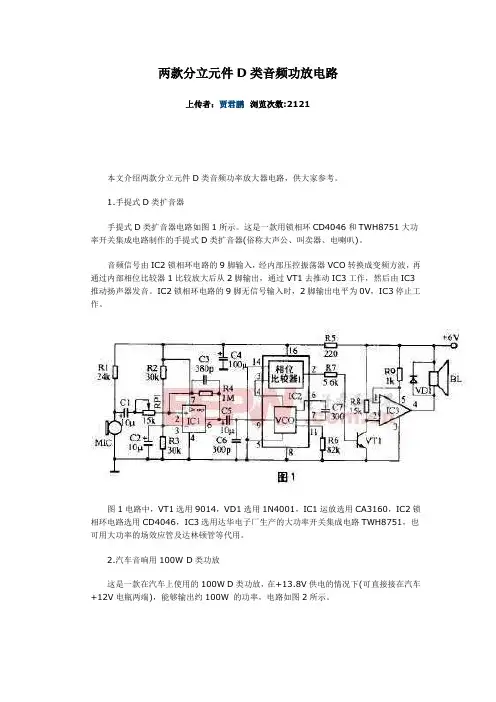
1.手提式D类扩音器手提式D类扩音器电路如图1所示。
这是一款用锁相环CD4046和TWH8751大功率开关集成电路制作的手提式D类扩音器(俗称大声公、叫卖器、电喇叭)。
音频信号由IC2锁相环电路的9脚输入,经内部压控振荡器VCO转换成变频方波,再通过内部相位比较器1比较放大后从2脚输出,通过VT1去推动IC3工作,然后由IC3推动扬声器发音。
IC2锁相环电路的9脚无信号输入时,2脚输出电平为0V,IC3停止工作。
图1电路中,VT1选用9014,VD1选用1N4001,IC1运放选用CA3160,IC2锁相环电路选用CD4046,IC3选用达华电子厂生产的大功率开关集成电路TWH8751,也可用大功率的场效应管及达林顿管等代用。
2.汽车音响用100W D类功放这是一款在汽车上使用的100W D类功放,在+13.8V供电的情况下(可直接接在汽车+12V电瓶两端),能够输出约100W 的功率,电路如图2所示。
在图2电路中,音频信号通过一个470nF电容耦合到双D触发器CD4013(IC1)的输入端,经过CD4013内部电路处理后,从Q、Q端输出两个含有音频成分的极性相反的信号,这两个极性相反的信号经过高速MOSFET驱动电路TC4426进行功率放大后,推动大功率MOSFET管IRFP140工作在开关状态,音频信号通过T2的耦合输出到扬声器中,推动扬声器发声。
图2电路在接阻抗为4~16Ω的扬声器时,均能正常工作,效率高于76%。
由于有输出变压器T2的存在,输出音色颇有胆机风味。
高速MOSFET驱动电路TC4426在4.5V~18V供电范围内均能稳定地工作,其输出驱动电流高达1.5A,而输出阻抗只有7Ω (内部电路如图3所示),因此是驱动MOSFET 功放管的理想器件。
由于该电路比较简单,很适合音响爱好者自制,故下面给出各元器件的参数,以便仿制。
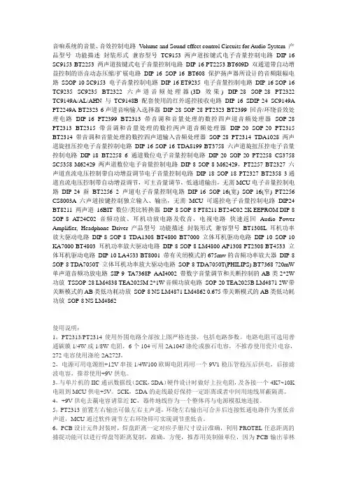
音响系统的音量、音效控制电路V olume and Sound effect control Circuits for Audio System 产品型号功能描述封装形式兼容型号TC9153 两声道按键式电子音量控制电路DIP-16 SC9153 BT2253 两声道按键式电子音量控制电路DIP-16 PT2253 BT609D 双通道带自动增益控制的语音动态压缩/扩展电路DIP-16 SOP-16 BT608 保护扬声器所设计的音频限幅电路SSOP-10 SC9153 电子音量控制电路DIP-16 ET9235 电子音量控制电路DIP-16 SOP-16 TC9235 SC9235 BT2322 六声道音频处理器(3D效果) DIP-28 SOP-28 PT2322 TC9149A/AL/AHN 与TC9148B配套使用的红外遥控接收电路DIP-16 SDIP-24 SC9149A PT2249A BT2323 6声道音响输入选择器DIP-28 SOP-28 PT2323 BT2399 回音/环绕音效处理电路DIP-16 PT2399 BT2313 带音调和音量处理的数控四声道音频处理器SOP-28 PT2313 BT2315 带音调和音量处理的数控两声道音频处理器DIP-20 SOP-20 PT2315 BT2314 带音调和音量处理的数控四声道输入音频处理器SOP-28 PT2314 TDA1028 两声道旋扭压控电子音量控制电路DIP-16 SOP-16 TDA8199 BT3758 六声道旋扭压控电子音量控制电路DIP-18 BT2258 6通道数位电子音量控制电路DIP-20 SOP-20 PT2258 CS3758 SC5358 M62429 两声道数位电子音量控制电路DIP-8 SOP-8 M62429,PT2257 BT2327 六声道直流电压控制带自动增益调节电子音量控制电路DIP-18 SOP-18 PT2327 BT2358 3通道直流电压控制带自动增益调节,可主音量调节,低通道输出,无需MCU电子音量控制电路DIP-24 新BT2256 2声道电子音量控制电路DIP-16 SOP-16(宽) SOP-16(窄) PT2256 CS8003A 六声道按键控制独立输入、输出,无需MCU可遥控电子音量控制电路DIP24 BT8211 两声道16BIT 数位/类比转换器DIP-8 SOP-8 PT8211 BT24C02 2K EEPROM DIP-8 SOP-8 AT24C02 音频功放、耳机功放电路及收音,电视电路快速返回Audio Power Amplifier, Headphone Driver 产品型号功能描述封装形式兼容型号BT1308L 耳机功率放大驱动电路DIP-8 SOP-8 TDA1308 BT4800 BT7000 立体耳机驱动电路DIP-10 SOP-10 KA7000 BT4803 耳机功率放大驱动电路DIP-8 SOP-8 LM4800 AP1308 PT2308 BT4533 立体耳机驱动电路DIP-10 LA4533 BT8001 带有关闭模式的675mw的音频功率放大器DIP-8 SOP-8 TDA7050T 立体耳机功率放大驱动电路SOP-8 TDA7050T(PHILIPS) BT7368 720mW 单声道音频功放电路SIP-9 TA7368P AAI4002 带数字音量调节和关断控制的AB类2*2W 功放TSSOP-28 LM4838 TEA2025M 2*1W音频功放电路SOP-20 TEA2025B LM4871 2W带关断模式的AB类低功耗功放SOP-8 NS LM4871 LM4862 0.675带关断模式的AB类低功耗功放SOP-8 NS LM4862使用说明:1,PT2313/PT2314使用外围电路全部按上图严格连接,包括电路参数。
世界名牌CD机解码芯片大全【转载】世界名牌CD机解码芯片大全世界名牌CD机解码芯片大全品牌解码芯片ACOUSTIC RESEARCH CD-07 SAA7220日本金嗓子ACCUPHASE DP65 8x PCM1702 (4/ch)ACCUPHASE DP85 AD1853ACCUPHASE DP90 PCM63ADC CD 250XR PCM54日本雅佳AKAI CD55 AD1856AKAI CD69 PCM63AKAI CD-A70 MB84053BAKAI CD-M839 PCM56英国ALBA CD420 PCM54ALCHEMIST NEXUS APD32A 2x TDA1549英国AMC CD60 PCM1716AMC CD8A MN6474 (Technics MASH)AMC CD8B PCM1716ANTHEM CD1 PCM1702英国雅俊ARCAM ALPHA 5 TDA1541ARCAM ALPHA 5 PLUS TDA1541A ARCAM ALPHA 6 SM5864ARCAM ALPHA 7 PCM1710 ARCAM ALPHA 7SE PCM1716 ARCAM ALPHA 8 SM5864AP ARCAM ALPHA 9 dCS RingDAC ARCAM CD72 PCM1716ARCAM CD92 dCS RingDAC ARCAM DELTA 270 PCM69ARCAM DELTA BOX 5 PCM67英国ARYE CX-7 PCM1738ARYE D-1 PCM1704美国雅格美AUDIO ALCHEMY ENGINE v3."0 AD1862意大利AUDIO ANALOGUE MAESTRO AD1855 AUDIO INNOVATIONS ALTO PCM1716英国AUDIO NOTE CD-1 PCM1710 AUDIO NOTE CD-2 AD1865 AUDIO NOTE DAC-3 PCM63美国AUDIO RESEARCH CD1 SAA7341英国奥迪兰博AUDIOLAB 8000 CD CS4329英国AVI SC2000MC PCM63 BLAUPUNKT CP2650 PCM54英国剑桥CAMBRIDGE AUDIO CD1 TDA1541 CAMBRIDGE AUDIO CD2 TDA1541 CAMBRIDGE AUDIO CD3 TDA1541A CAMBRIDGE AUDIO CD4SE CS4327 CAMBRIDGE AUDIO CD6 TDA1305T CAMBRIDGE AUDIO D500 CS4327 美国CARVER SD/A 450 MN6474日本C.E.C. 530CD2 Y3015C.E.C. 680CD LC7881CONDOR CD950 YM3020谷中兰COPLAND CDA277 PCM63 COPLAND CDA288 PCM63-K皇冠CROWN CD2111R LC7881 英国CYRUS CD7 PCM1716 CYRUS dAD1 TDA1311 CYRUS dAD3 TDA1305 CYRUS dAD3Q AD1861 CYRUS dAD7 AD1861日本天龙DENON DA-500 PCM1702 DENON DCD-435 PCM1716E DENON DCD-480 PCM61 DENON DCD-485 PCM1735DENON DCD-500 PCM54 DENON DCD-580 PCM67P DENON DCD-590 PCM61 DENON DCD-615 PCM61P DENON DCD-635 PCM61P DENON DCD-650F PCM1700P DENON DCD-655 PCM1702 DENON DCD-680 PCM69A DENON DCD-685 PCM1702 DENON DCD-690 PCM61 DENON DCD-695 PCM61 DENON DCD-700 PCM54HP DENON DCD-725 PCM61P-L DENON DCD-735 PCM61 DENON DCD-755AR PCM1702 DENON DCD-800 PCM54 DENON DCD-820 PCM56 DENON DCD-890 PCM61P DENON DCD-920 PCM61 DENON DCD-980 PCM61P DENON DCD-1015 PCM61PDENON DCD-1100 PCM53JP-V DENON DCD-1400 PCM56 DENON DCD-1420 PCM54HP DENON DCD-1450AR PCM1702 DENON DCD-1500 PCM54HP-K DENON DCD-1500mk2 PCM56P-J DENON DCD-1520 PCM64 DENON DCD-1530 PCM61 DENON DCD-1550R PCM61 DENON DCD-1550AR PCM61P DENON DCD-1560 PCM1701 DENON DCD-1650R PCM1702 DENON DCD-1800 PCM53 DENON DCD-2560 4x AD1862 DENON DCD-2700 4x PCM1702J DENON DCD-S10/3000 PCM1702J DENON DCD-3300 PCM56P-K DENON DCD-3520 PCM64 DENON DCD-3560 PCM58P-K DENON DCD-S1 PCM1702 DENON DCM-280 PCM1748DENON RCD-100 PCM1710 DENON UCD-F10 PCM61DIORA CD-502 TDA1543DUAL CD130 CX20017DUAL CD20 PCM53EXPOSURE CD TDA1545AEZO FOG STAGE3 AD1853 FISCHER AD935 LC7881 FISCHER Z1 PCM58德国根德GRUNDIG CD103 LC7881 GRUNDIG CD9000 TDA1541A美国哈曼卡顿HARMAN KARDON HD200 YM3020 HARMAN KARDON HD500 PCM53 HARMAN KARDON HD710 MN6474 HARMAN KARDON HD720 PCM1710 HARMAN KARDON HD730 SAA7350 HARMAN KARDON HD760 PCM1702 HARMAN KARDON HD7225 MN6474 HARMAN KARDON HD7300 PCM61HARMAN KARDON HD7325 MN6474 HARMAN KARDON HD7525 PCM61P法国轩乐士HELIOS MODEL1S CS4328 (36 bit, ETNA) HELIOS MODEL2S CS4328 (36 bit, ETNA) HELIOS MODEL3S CS4328 (36 bit, ETNA) HELIOS STARGATE CS4328 (36 bit, ETNA) HEYBROOK SIGNATURE PCM67HIGH TECH GOLDLINE CX904 YM3020日本胜利JVC XL V22 PCM54JVC XL V221 LC7881JVC XL V250BK PCM56JVC XL V311BK MN6471JVC XL V464 MN35500JVC XL V1100 PCM54日本健伍KENWOOD DP47 TD6720N KENWOOD DP460 TD6709N KENWOOD DP850 CX20152 KENWOOD DP1080 LC78620EKENWOOD DP1100D CX20152 KENWOOD DP1510 PCM56 KENWOOD DP2000 CX20152 KENWOOD DP2010 PCM56P KENWOOD DP2080 LC78620E (LC78820) KENWOOD DP3080 SM5864 KENWOOD DP4090 KAN03 KENWOOD DP5020 PCM1701P KENWOOD DP5090 MN35502 JVC KENWOOD DP7002 PCM1702 KENWOOD DP7030 CXD2552 KENWOOD DP7060 TDA1547 KENWOOD DP7090 8x PCM1702 KOREA CHINA CD 022 KDA0316LN KOREA HCD 630 Y3015美国KRELL KAV280 PCM1704英国莲LINN GENKI PCM1723日本力士LUXMAN D 102 TD6709NLUXMAN D 103 PCM1701LUXMAN D 112 1x PCM56LUXMAN D2 92 LC7881日本马兰士MARANTZ CD7 TDA1541AS2 (double crown) MARANTZ CD10 TDA1547MARANTZ CD14 TDA1547MARANTZ CD15 TDA1547MARANTZ CD16D TDA1547MARANTZ CD17mkII TDA1547 MARANTZ CD19 SM5872MARANTZ CD38 TDA1545MARANTZ CD40 TDA1541AMARANTZ CD43 SM5872BSMARANTZ CD45 TDA1540MARANTZ CD48 TDA1549MARANTZ CD52 SAA7321GPMARANTZ CD53 SM5872BSMARANTZ CD63 SM5872BSMARANTZ CD63II SM5872MARANTZ CD63mkII KI SM5872 MARANTZ CD63SE SM5872BS MARANTZ CD65 TDA1541MARANTZ CD67 SM5872MARANTZ CD67SE SM5872MARANTZ CD67II OSE SM5872MARANTZ CD72 SAA7350MARANTZ CD74 TDA1540MARANTZ CD84 TDA1540MARANTZ CD85 TDA1541MARANTZ CD94 TDA1541AMARANTZ CD94II 2x TDA1541AS1 (single crown) MARANTZ CD4000 TDA1545MARANTZ CD5000 TDA1549MARANTZ CD6000 SM5872MARANTZ CD6000KI SM5872美国马克,列文森MARK LEVINSON N\'36 PCM1702 (vagy PCM1704) MARK LEVINSON No. 390S AD1853MERIDIAN 508 CS4329法国美格MICROMEGA LEADER SAA7321GP MICROMEGA LOGIC SAA7321MICROMEGA PREMIUM18 CS4327MICROMEGA STAGE2 SAA7321GP MICROMEGA STAGE6 TDA1305英国美声MISSION dAC5 TDA1547 MISSION dAD3 TDA1305 MISSION PCM4000 TDA1541日本三菱MITSUBISHI DP109 PCM56 MITSUBISHI MC5100 PCM56英国音乐传真MUSICAL FIDELITY A2 YDC103 MUSICAL FIDELITY DIGILOG TDA1541 MUSICAL FIDELITY E60 YDC103 MUSICAL FIDELITY E624 PCM1716英国美丽安MYRYAD T-10 CS4327MYRYAD T-20 CS4327MYRYAD MC100 CXD2565英国NAD 502 MN6474AMNAD 510 SAA7350NAD 512 MN6474NAD 522 PCM1710NAD C541i PCM1710NAD 5100 PCM56NAD 5325 LC7881NAD 5425 MN6471MNAD C520 PCM1710NAD S500 CS4390英国NAIM AUDIO CD1 TDA1541NAIM AUDIO CD2 TDA1541NAIM AUDIO CD3 TDA1541NAIM AUDIO CD3."5 TDA1305NAIM AUDIO CD5 TDA1305NAIM AUDIO CDI TDA1541AS1 (single crown) NAIM AUDIO CDS11 PCM1702K日本中道NAKAMICHI CD PLAYER 1 PCM1700P NAKAMICHI CD PLAYER 4 AD1864N NAKAMICHI MB 4 LC78840NAKAMICHI MB 5 LC78840NAKAMICHI CDP 2E TDA1541ANAKAMICHI OMS 1E PCM56NAKAMICHI OMS 4E PCM54NAKAMICHI OMS 5E TDA1540NAKAMICHI OMS 7E PCM54日本NEC CD610 PCM54日本安桥ONKYO DX-704 MN6472 (Technics MASH) ONKYO DX-6430 YM3020ONKYO DX-6470 PCM56ONKYO DX-6550 Integra TC9219 (ONKYO 8D-3170-1) ONKYO DX-6570 PCM58ONKYO DX-6620 LC7881ONKYO DX-6850 Integra 2x SM5861ONKYO DX-7011 TC9237ONKYO DX-7211 SM5874ONKYO DX-7333 TC9268PONKYO DX-7500 ONKYO 8S-3380-1ONKYO DX-7711 Integra SM5864APONKYO DX-7911 Integra SM5864AP美国PARASOUND CD M839 PCM56 PARASOUND C/DP1000 PCM67 荷兰飞利浦PHILIPS CD-80 TDA1541 PHILIPS CD-100 TDA1540 PHILIPS CD-104 TDA1540 PHILIPS CD-200 TDA1540 PHILIPS CD-202 TDA1540 PHILIPS CD-204 TDA1540 PHILIPS CD-210 TDA1543 PHILIPS CD-304 TDA1540 PHILIPS CD-304 MkII TDA1541 PHILIPS CD-460 TDA1541 PHILIPS CD-465 TDA1541 PHILIPS CD-471 TDA1541 PHILIPS CD-482 TDA1543 PHILIPS CD-610 TDA1541 PHILIPS CD-614 TDA1543 PHILIPS CD-634 SAA7321PHILIPS CD-721 TDA1545APHILIPS CD-723 TDA1545PHILIPS CD-750 SAA7350PHILIPS CD-751 TDA1549PHILIPS CD-753 TDA1549PHILIPS CD-880 TDA1541PHILIPS CD-910 SAA7341GP PHILIPS CD-930 SAA7350PHILIPS CD-931 SAA7350PHILIPS CD-950 TDA1547PHILIPS CD-951 TDA1547PHILIPS CD-960 TDA1541PHILIPS CDR-950 new AD1855 PHILIPS LHH-100 TDA1547PHILIPS LHH-500 TDA1547PHILIPS LHH-600 TDA1547PHILIPS LHH-800 TDA1547PHILIPS LHH-1000 TDA1541 PHILIPS MAGNAVOX CDB-560 TDA1541 PHILIPS MAGNAVOX CDB-650 TDA1541PINK TRIANGLE NUMERAL TDA1305T日本先锋PIONEER DV-717 PE8001APIONEER PD-52 PD2028PIONEER PD-75 PD2028A (vagy PD2028B) PIONEER PD-93 PD2028APIONEER PD-95 PD2028A (vagy PD2028B) PIONEER PD-204 PD2026BPIONEER PD-4500 PCM1700 PIONEER PD-4550 PCM1700P PIONEER PD-5100 PD0034PIONEER PD-5300 PCM56PIONEER PD-5700 PD2026A PIONEER PD-7300 PCM58PPIONEER PD-7700 PD2026A PIONEER PD-9700 PD2028A PIONEER PDR-04 AKM4321PIONEER PDR-609 PCM1716 PIONEER PDR-W739 PCM1716 PIONEER PDR-W839 PCM1716 PIONEER PD-S06 PCM1702JPIONEER PD-S502 PD2026B PIONEER PD-S505 PD2029A PIONEER PD-S507 PE8001A PIONEER PD-S605 PD2029A PIONEER PD-S703 PD2029A PIONEER PD-S707 PE8001A PIONEER PD-S801 PD2028 PIONEER PD-S802 PD2028B PIONEER PD-S901 PD2028B 丹麦翩美PRIMARE D20 AKM4324 PRIMARE D302 4x PCM1702 美国PROCEED PCD2 PCM58P 台湾普腾PROTON AC423 LC78820 PROTON AC424 TDA1311A英国国都QUAD66 TDA1541AQUAD77 CS4328英国君子REGA PLANET PCM1710U瑞士REVOX B225 TDA1540 REVOX B226 TDA1541 REVOX C221 SAA7310英国乐圣ROKSAN ATTESSA DP3P CS4328 ROKSAN CASPIAN TDA1305英国路遥ROTEL RCD-02 PCM1732 ROTEL DCM-9PRO PCM63 ROTEL RCD-855 TDA1541 ROTEL RCD-856BX SAA7323 ROTEL RCD-865BX SAA7323 ROTEL RCD-945AX SAA7341GP T ROTEL RCD-955 TDA1541 ROTEL RCD-965BX SAA7323GP T ROTEL RCD-970BX TDA1305T ROTEL RCD-971 PCM63 ROTEL RCD-975 TDA1305T ROTEL RCD-991 PCM63P ROTEL RCD-1070 PCM1732日本SANSUI CD V1000 PCM56日本三洋SANYO CP489 LC7881SEG CD200 YM3020日本夏普SHARP DX112 IR 3K16BMSHARP DX650 LC7880美国狮龙SHERWOOD CD1 TDA1547 SHERWOOD CD1060C D6372 CX SHERWOOD CD1160R PCM56 SHERWOOD CD1192R YM4113B SHERWOOD CDC2000C μPD6376 SHERWOOD CDC2010RC μPD6376 SHERWOOD CD4030R SAA7350BS SIMAUDIO MOON ECLIPSE 4x PCM1704K日本SONIC FRONTIERS SFCD1 UltraAnalog D20400A SONY CDP-40 1x PCM54SONY CDP-101 CX20017SONY CDP-222ES PCM56P JSONY CDP-227ESD TDA1541SONY CDP-228ESD PCM58PSONY CDP-302ES CX20152SONY CDP-303ESII CX20152 SONY CDP-333ESA CXD2562 SONY CDP-333ESD TDA1541 SONY CDP-333ESJ CXD2562 SONY CDP-337ESD TDA1541 SONY CDP-497 CXD2561 SONY CDP-501ES CX20017 SONY CDP-502 PCM54SONY CDP-502ES CX20152 SONY CDP-520ESII CX20152 SONY CDP-552 PCM54SONY CDP-553ESD PCM53JP-V K SONY CDP-555ESA CXD2562 SONY CDP-555ESD TDA1541A SONY CDP-555ESJ CXD2562 SONY CDP-557ESD PCM58P SONY CDP-620 PCM54SONY CDP-650 PCM54SONY CDP-701ES CX20017 SONY CDP-707ESD PCM58P SONY CDP-777ESA CXD2562QSONY CDP-MS1 CXD8594 + CXA8042AS SONY CDP-R3 + DAS-R1aCXD2552Q + CXD2552 SONY CDP-X229ES CXD2562QSONY CDP-X3000 CXD2562Q + CXA8042AS SONY CDP-X303ES CXD2562QSONY CDP-X5000 CXD2562 + CXA8042 SONY CDP-X505ES CXD2562QSONY CDP-X33ES CXD2552QSONY CDP-X55ES CXD2552SONY CDP-X777ES CXD2552BQSONY CDP-X779ES CXD2562SONY CDP-X77ES CXD2552SONY CDP-X7ESD PCM58P SSONY CDP-X900 CXA8042SONY CDP-XA30ES CXD2562Q + CXA8042AS SONY CDP-XA50ES CXA8042ASSONY CDP-XA55ES CXD8594Q + CXA8042S SONY CDP-XA5ES CXD2562Q + CXA8042AS SONY CDP-XA7ES CXD2562 + CXA8042AS SONY CDP-XB920 CXD8715 + CXA8355 SONY CDP-XB720E CXD8735NSONY CDP-XB930 CXD8735NSONY CDP-XE300 CXD8567SONY CDP-XE330 CXD2529QSONY CDP-XE900 CXD8505 + CXA8055 SONY DAS-R1 TDA1541AS1 (single crown) SOUND WAVE CD1100 LC7881 SUDGEN OPTIMA TDA1543SUDGEN SDA-1 TDA1541SUDGEN SDT-1 TDA1541AS1 (single crown) T+A CD1210R SM5864AP英国麦拉伦TAG McLAREN CD20R CS4329TALK ELECTRONICS THUNDER 3CS4390 TASCAM CD201 MN6474日本第一音响TEAC PD155mk2 Y3015TEAC PD160 TC9218FTEAC PD365 YM7121BTEAC VRDS 7 TDA1547TEAC VRDS 8 PCM1702TEAC VRDS 9 PCM1702TEAC VRDS 10SE TDA1547TEAC VRDS 25 AD1862JTEAC ZD5000 PCM53日本乐声TECHNICS SL-P1 PCM53TECHNICS SL-P2 PCM53TECHNICS SL-P110 PCM54HPTECHNICS SL-P120K E PCM54HP TECHNICS SL-P272A MN6474TECHNICS SL-P770 2x PCM56P + 2x PCM56P-J TECHNICS SL-P990 4x PCM56P-J TECHNICS SL-P1200 PCM54HP TECHNICS SL-PG480A MN662713 TECHNICS SL-PJ28A MN6477TECHNICS SL-PS670D MN6474 TECHNICS SL-PS700 MN6474TECHNICS SL-PS770A MN64733美国THETA DSP PCM67法国汤姆逊THOMSON LAD300 TD6720N THULE CD100 CS4303THULE SPIRIT PCM1715U日本TOSHIBA XR40 TD6705AP UHER UCD-210 LC7882 UNIVERSUM CD4682 PCM56 USHER CD-100 PCM1732美国怀念WADIA 23 AD1865WADIA 850 PCM1702 WADIA 860 4x PCM1702 WADIA 861 4x PCM1704日本雅马哈YAMAHA CD-2 PCM53 YAMAHA CD-3 PCM53 YAMAHA CD-2000 PCM54HP YAMAHA CDX-3 PCM54 YAMAHA CDX-410 PCM56 YAMAHA CDX-420 PCM56 YAMAHA CDX-470 YDC103 YAMAHA CDX-480 MN66271 YAMAHA CDX-490 MN66271R YAMAHA CDX-580 YAC514 YAMAHA CDX-590 YAC514YAMAHA CDX-593 YAC514 YAMAHA CDX-700 PCM56 YAMAHA CDX-880 YAC514 YAMAHA CDX-900 PCM56 YAMAHA CDX-890 YAC514 YAMAHA CDX-893 YAC514 YAMAHA CDX-993 YAC514F YAMAHA CDX-1100 PCM56 YAMAHA CDX-20 PCM58。
一款发烧音频解码器的设计与制作摘要:随着数字音频时代的来临,数字音源也不断丰富,然而这些数字音频设备内建的采用一体化设计,易受干扰,解码出来的声音并不尽人意。
一般的数字音源如、、网络机顶盒等都配备了光纤和同轴输出接口,把数字音频信号绕开机内的,直接送到专门的音频解码器,由专门的解码器完成转换,实现声音的高保真重放。
本文本着的设计原则,设计一款立体声音频解码器,由317、431组成多路甲类并联稳压供电,采用经典的高性能的8412负责数字信号的接收与解调、1700P 数字滤波、2R架构的1702做转换、挑选发烧运放担任和,完成数字信号的接收并转换成高保真的音频信号,再通过一级电子管校音线路,输出驱动信号可以直接推动后级的甲类晶体管功放。
实现效果的重放。
关键词:音频解码器 1702 电子管校音高保真甲类并联稳压1. 引言:一些低中档数字音源输出的音频声音生硬,数码声重,音质刺耳烦躁,不耐听,满足不了音响发烧友的听觉需求。
主要是因为这些机器内建的音频性能差,模拟滤波、放大器件普通,供电也过于简单造成。
好在这些机器一般都配有光纤或者同轴输出端口,提供数字音频信号输出,供高档的音频解码还原高保真的声音。
有动手能力的烧友都喜欢一台高性能的音频解码器以重放的音响效果,满足自己的听觉需求。
2. 音频解码器电路的设计2.1 音频解码器电路组成音频解码器由数字信号接收器、数字滤波器、转换器、转换器、滤波器将数字音频还原还原成模拟音频信号,再通过电子管组成的和田茂氏线路校音、开机延迟吸合电路控制输出模拟音频信号推动后级功放。
电路的组成及其信号流如图1:图1 音频解码器组成及信号流程2.2 数字信号接收与音频解码电路数字信号的接收与解码电路关系到音频信号还原的质量,想要得到高保真的声音,必需采用高性能的器件担当音频解码的重任,这是重点部分,电路原理图见图2,下面对其原理作进一步的分析:2.2.1 数字信号接收器数字信号接收采用美国公司的带有的解调芯片8412担任,能自动识别3248K采样率。
AD系列芯片1.模数转换器……AD1380JD 16位20us高性能模数转换器(民用级)AD1380KD 16位20us高性能模数转换器(民用级)AD1671JQ 12位1.25MHz采样速率带宽2MHz模数转换器(民用级)AD1672AP 12位3MHz采样速率带宽20MHz单电源模数转换器(工业级)AD1674JN 12位100KHz采样速率带宽500KHz模数转换器(民用级)AD1674AD 12位100KHz采样速率带宽500KHz模数转换器(工业级)AD570JD/+ 8位25us模数转换器(民用)DIPAD574AJD 12位25us模数转换器(民用)DIPAD574AKD 12位25us模数转换器(民用)DIPAD578KN 12位3us模数转换器(民用)DIPAD6640AST 12位65MSPS模数转换器(工业级) LQFPAD6644AST 14位65MSPS模数转换器(工业级) LQFPAD676JD 16位100KSPS采样速率并行输出模数转换器(民用级)DIPAD676JN 16位100KSPS采样速率并行输出模数转换器(民用级)DIPAD676KD 16位100KSPS采样速率并行输出模数转换器(民用级)DIPAD677AR 16位100KSPS采样速率串行输出模数转换器(民用级)SOICAD677JD 16位100KSPS采样速率串行输出模数转换器(民用级)DIPAD677JN 16位100KSPS采样速率串行输出模数转换器(民用级)DIPAD678JD 12位200KSPS采样速率并行输出模数转换器(民用级)DIPAD678KN 12位200KSPS采样速率并行输出模数转换器(民用级)DIPAD679JN 14位128KSPS采样速率并行输出模数转换器(民用级)DIPAD679KN 14位128KSPS采样速率并行输出模数转换器(民用级)DIPAD7660AST 16位100KSPS CMOS模数转换器(工业级)LQFPAD7664AST 16位570KSPS CMOS模数转换器(工业级)LQFPAD7701AN 16位∑–△模数转换器(工业级)DIPAD7703AN 20位∑–△模数转换器(工业级)DIPAD7703BN 20位∑–△模数转换器(工业级)DIPAD7705BN 16位∑–△模数转换器(工业级)DIPAD7705BR 16位∑–△模数转换器(工业级)SOICAD7706BN 16位∑–△模数转换器(工业级)DIPAD7707BR 16位∑–△模数转换器(工业级)SOICAD7710AN 24位∑–△模数转换器(工业级)DIPAD7711AN 24位∑–△模数转换器(工业级)DIPAD7712AN 24位∑–△模数转换器(工业级)DIPAD7713AN 24位∑–△模数转换器(工业级)DIPAD7714AN-3 24位∑–△模数转换器(工业级)DIP 3V 电源AD7714AN-5 24位∑–△模数转换器(工业级)DIP 5V电源AD7715AN-5 16位∑–△模数转换器(工业级)DIP 5V电源AD7715AR-5 16位∑–△模数转换器(工业级)SOIC 5V电源AD7731BN 24位∑–△模数转换器(工业级)DIPAD779JD 14位128KSPS采样速率并行输出模数转换器(民用级)DIPAD7820KN 8位500KSPS采样速率模数转换器(民用级)DIPAD7821KN 8位1MSPS采样速率模数转换器(民用级)DIPAD7822BN 8位2MSPS采样速率模数转换器(工业级)DIPAD7824BQ 8位四通道高速模数转换器(民用级)DIPAD7824KN 8位四通道高速模数转换器(工业级)DIPAD7856AN 14位8通道285KSPS采样速率模数转换器(工业级)DIPAD7862AN-10 12位4通道同时采样250KSPS速率模数转换器带2SHA and 2ADCs(工业级)DIPAD7864AS-1 12位4通道同时采样147KSPS速率模数转换器(工业级)PQFPAD7865AS-1 14位4通道同时采样175KSPS速率模数转换器带2SHA and 2ADCs(工业级)PQFPAD7872AN 14位串行输出模数转换器(工业级)DIPAD7891AP-1 12位四通道同时采样模数转换器(工业级)DIPAD7892AN-1 12位四通道同时采样模数转换器(工业级)SOICAD7895AN-10 12位750KSPS采样速率模数转换器(民用级)DIPAD7874AN 12位750KSPS采样速率模数转换器(民用级)DIPAD7874BR 12位8通道200KSPS速率模数转换器(工业级)SOICAD7886JD 12位单电源八通道串行采样模数转换器(工业级)DIPAD7886KD 12位单电源八通道串并行采样模数转换器(工业级)DIPAD7888AR 12位600KSPS采样模数转换器(工业级)DIPAD7890AN-10 12位单电源200KSPS采样速率模数转换器(工业级)DIPAD9042AST 12位41MSPS模数转换器(工业级)LQFPAD9048JQ 8位35MSPS视频模数转换器(民用级)DIPAD9049BRS 9位30MSPS模数转换器(工业级)SSOPAD9050BR 10位40MSPS模数转换器(工业级)SOICAD9051BRS 10位60MSPS模数转换器(工业级)SSOPAD9057BRS-40 8位40MSPSz视频模数转换器(工业级)SSOPAD9057BRS-60 8位60MSPS视频模数转换器(工业级)SSOPAD9058JJ 双路8位50MSPS视频模数转换器(民用级)LCCAD9059BRS 双路8位60MSPS视频模数转换器(工业级)SSOPAD9066JR 双路6位60MSPS视频模数转换器(民用级)SSOPAD9071BR 10位TTL兼容100MSPS模数转换器(工业级) SOICAD9200ARS 10位20MSPS模数转换器(工业级) SSOPAD9203ARU 10位40MSPS模数转换器(工业级) TSSOPAD9220AR 12位10MSPS模数转换器(工业级) SOICAD9221AR 12位1MSPS模数转换器(工业级) SOICAD9223AR 12位3MSPS模数转换器(工业级) SOICAD9225AR 12位25MSPS模数转换器(工业级) SOICAD9226ARS 12位65MSPS模数转换器(工业级) SSOPAD9240AS 14位10MSPS模数转换器(工业级) MQFPAD9243AS 14位3MSPS模数转换器(工业级) MQFPAD9260AS 16位2.5MSPS∑–△模数转换器(工业级)MQFPAD9280ARS 单电源8位32MSPS模数转换器(工业级)SSOPAD9281ARS 单电源8位双路32MSPS模数转换器(工业级)SSOPAD9283BRS-100 单电源8位100MSPS模数转换器(工业级)SSOPAD9283BRS-80 单电源8位80MSPS模数转换器(工业级)SSOPAD9288BRS-80 单电源8位双路80MSPS模数转换器(工业级)SSOPAD976CN 16位100KSPS BiCMOS并行输出模数转换器(工业级)DIPAD976AN 16位100KSPS BiCMOS并行输出模数转换器(工业级)DIPAD976AAN 16位200KSPS BiCMOS并行输出模数转换器(工业级)DIP2. 隔离放大器AD202JN 小型2KHz隔离放大器(民用级)卧式AD202JY 小型2KHz隔离放大器(民用级)立式AD204JN 小型5KHz隔离放大器(民用级)卧式AD261BND-1 数字隔离放大器3. 温度传感器AD22100KT 带信号调理比率输出型温度传感器AD22105AR 可编程温控开关电阻可编程温度控制器SOICAD590JH —55℃~150℃测温范围温度传感器TO-52AD590KH —55℃~150℃测温范围温度传感器TO-52AD592AN 低价格,精密单片温度传感器TO-92AD592BN 低价格,精密单片温度传感器TO-92AD7416AR 片内带D/A 数字输出温度传感器LM35升级品可8片级联(工业级)SOIC ADXL105JQC ±1g-±5g带温度补偿加速度传感器(民用级)QC-14ADXL202AQC ±2g双路加速度传感器(工业级)QC-144. 数字同步调制器AD9830AST 带10位D/A,25MHz主频直接数字同步调制器(工业级)PQFPAD9831AST 带10位D/A,50MHz主频直接数字同步调制器(工业级)PQFPAD9832BRU 带10位D/A,25MHz主频直接数字同步调制器(工业级)TSSOPAD9850BRS 带10位D/A,125MHz主频直接数字同步调制器(工业级)SSOPAD9851BRS 带10位D/A,180MHz主频直接数字同步调制器(工业级)SSOPAD9852AST 带12位D/A,200MHz主频直接数字同步调制器(工业级)LQFP-80AD9852ASQ 带散热器带12位D/A,300MHz主频直接数字同步调制器(工业级)LQFP-80AD9853AS 数字QPSK/16 QAM 调整器(工业级)PQFPAD9854AST 带12位D/A,200MHz主频直接数字同步调制器(工业级)LQFP-80AD9854ASQ 带散热器带12位D/A,300MHz主频直接数字同步调制器(工业级)LQFP-80AD7008AP20 带10位D/A,20MHz主频直接数字同步调制器(工业级)PLCCAD7008JP-50 带10位D/A,50MHz主频直接数字同步调制器(民用级)PLCC5.振荡器AD2S99AP 可编程正弦波振荡器(工业级)PLCCAD537JH 150KHZ集成压频转换器(民用级)TO-99AD537SH 150KHZ集成压频转换器(军用级)TO-99AD650JN 1MHz,电压频率转换器(民用级)DIPAD650KN 1MHz,电压频率转换器(民用级)DIPAD652AQ 2MHz,同步电压频率转换器(工业级)DIPAD654JR 500KHz,低价格电压频率转换器(民用级)SOICAD654JN 500KHz,低价格电压频率转换器(民用级)DIPAD7741BN 单通道输入6MHz压频转换器(工业级)DIPAD7742BN 四通道输入6MHz压频转换器(工业级)DIPAD7750AN 两通道乘积/频率转换器电度表专用芯片(工业级)DIPAD7755AARS IEC521/1036标准电度表专用芯片(工业级)DIPADVF32KN 500KHz工业标准压频转换器(民用级)DIP6. 数模转换器AD420AN-32 16位单电源4-20mA输出数模转换器(工业级)DIPAD420AR-32 16位单电源4-20mA输出数模转换器(工业级)SOICAD421BN 16位环路供电符合HART协议4-20mA输出数模转换器(工业级)DIPAD421BR 16位环路供电符合HART协议4-20mA输出数模转换器(工业级)SOICAD557JN 微处理器兼容完整7位电压输出数模转换器(民用)DIPAD558JN 微处理器兼容完整8位电压输出数模转换器(民用)DIPAD565AJD 12位0.25us电流输出数模转换器(民用)DIPAD568JQ 12位超高速电流输出数模转换器(民用)DIPAD569JN 16位3us电流输出数模转换器(民用)DIPAD660AN 16位8us串并行输入数模转换器(工业级)DIPAD667JN 12位3us并行输入数模转换器(民用级)DIPAD667KN 12位3us并行输入数模转换器(民用级)DIPAD669AN 16位8us并行输入数模转换器(工业级)DIPAD670JN 单电源,内带仪表放大器电压基准源8位数模转换器(民用级)DIPAD7111ABN 0.37db对数数模转换器(工业级)DIPAD7111LN 0.37db对数数模转换器(工业级)DIPAD7224KN 8位3us转换时间电压输出数模转换器(民用级)DIPAD7226KN 8位4通道3us转换时间电压输出数模转换器(民用级)DIPAD7228ABN 8位8通道5us转换时间电压输出数模转换器(工业级)DIPAD7237AAN 12位2通道5us转换时间电压输出数模转换器(工业级)DIPAD7237JN 12位2通道5us转换时间电压输出数模转换器(民用级)DIPAD7243AN 12位电压输出型数模转换器(工业级)DIPAD7245AAN 12位10us转换时间电压输出数模转换器(工业级)DIPAD7249BN 12位双路串行输出数模转换器(工业级)DIPAD7520LN 10位CMOS数模转换器(民用级)DIPAD7523JN 8位CMOS数模转换器(民用级)DIPAD7524JN 8位CMOS带锁存数模转换器(民用级)DIPAD7528JN 8位180ns电流输出CMOS数模转换器(民用级)DIPAD7528KN 8位180ns电流输出CMOS数模转换器(民用级)DIPAD7533JN 10位600ns电流输出CMOS数模转换器(民用级)DIPAD7535JN 14位1.5us电流输出CMOS数模转换器(民用级)DIPAD7537JN 12位双路1.5us电流输出CMOS数模转换器(民用级)DIPAD7541AKN 12位600ns电流输出CMOS数模转换器(民用级)DIPAD7542JN 12位250ns电流输出CMOS数模转换器(民用级)DIPAD7543KN 12位串行输入CMOS数模转换器(民用级)DIPAD7545AKN 12位1us电流输出CMOS数模转换器(民用级)DIPAD7564BN 低功耗四路数模转换器(工业级)DIPAD7574JN 8位15us电流输出CMOS数模转换器(民用级)DIPAD767JN 12位高速电压输出数模转换器(民用级)DIPAD768AR 16位高速电流输出数模转换器(民用级)SOICAD7837AN 12位双路乘法数模转换器(工业级)DIPAD7845JN 12位乘法数模转换器(民用级)DIPAD7846JN 16位电压输出数模转换器(民用级)DIPAD7847AN 12位双路乘法数模转换器(工业级)DIPAD8522AN 12 位单电源双路电流输出型数模转换器(工业级)DIPAD9708ARU 8位100MSPS 双路数模转换器(工业级)TSSOPAD9709AST 8位125MSPS 双路数模转换器(工业级)PQFPAD9713BAN 12位80MSPS TTL兼容数模转换器(工业级) DIPAD9721BR 10位400MSPS TTL兼容数模转换器(工业级) SOICAD9731BR 10位170MSPS 双电源数模转换器(工业级) SOICAD9732BRS 10位200MSPS 单电源数模转换器(工业级) SSOPAD9750AR 10位125MSPS 数模转换器(工业级)SOICAD9752AR 12位125MSPS 数模转换器(工业级)SOICAD9760AR 10位100MSPS 数模转换器(工业级)SOICAD9762AR 12位100MSPS 数模转换器(工业级)SOICAD9764AR 14位100MSPS 数模转换器(工业级)SOICAD9772AST 14位300MSPS 数模转换器(工业级)LQFPAD977AAN 16位200KSPS BiCMOS串行输出数模转换器(工业级)DIPAD977AN 16位100KSPS BiCMOS串行输出数模转换器(工业级)DIP7. 运放AD515AJH 低价格,低偏置电流,高输入阻抗运放(民用级) TO-99AD515ALH 低价格,低偏置电流,高输入阻抗运放(民用级) TO-99AD517JH 低失调电压,高性能运放(民用级) TO-99AD518JH 宽带,低价格运放(民用级) TO-99AD521JD 电阻设置增益精密仪表放大器(民用级)DIPAD524AD 引脚设置增益高精度仪表放大器(工业级)DIPAD526BD 软件编程仪表放大器(工业级)DIPAD526JN 软件编程仪表放大器(民用级)DIPAD542JH 低价格,低偏置电流,高输入阻抗运放(民用级) TO-99AD545ALH 低偏置电流,高输入阻抗运放(民用级) TO-99AD546JN 静电计放大器(民用级)DIPAD547JH 低价格,低偏置电流,高输入阻抗运放(民用级) TO-99AD548JN 精密BiFET输入运放(民用级)DIPAD549JH 低偏置电流,高输入阻抗运放(民用级) TO-99AD549LH 低偏置电流,高输入阻抗运放(民用级) TO-99AD5539JN 高速运放(民用级)DIPAD582KD 0.7us采样保持放大器(民用)DIPAD585AQ 3us采样保持放大器(工业级)DIPAD684JQ 1us 四通道采样保持放大器(民用级)DIPAD781JN 700ns采样保持放大器(民用级)DIPAD9101AR 7ns建立时间采样保持放大器(工业级)SOIC AD600XN 低噪声宽带可变增益双运放(民用级)DIPAD602JN 低噪声宽带可变增益双运放(民用级)DIPAD603AQ 低噪声可变增益运放(工业级)DIPAD606JN 50MHz, 80db对数放大器(民用级)DIPAD620AN 低功耗仪表放大器(工业级)DIPAD621AN 低功耗仪表放大器(工业级)DIPAD622AN 单电源仪表放大器(工业级)DIPAD623AN 单电源Rail-Rail输出仪表放大器(工业级)DIPAD623AR 单电源Rail-Rail输出仪表放大器(工业级)SOICAD624AD 精密仪表放大器(工业级)DIPAD625JN 可编程增益仪表放大器(民用级)DIPAD625KN 可编程增益仪表放大器(民用级)DIPAD626AN 单电源仪表放大器(工业级)DIPAD627AN 单电源低功耗Rail-Rail输出仪表放大器(工业级)DIPAD629AN 高电压抑制比差分放大器(工业级)DIPAD648JN 精密,BiFET输入运放(民用级)DIPAD704JN 精密四运放(民用级)DIPAD705JN 精密运放(民用级)DIPAD706JN 精密双运放(民用级)DIPAD707AQ 精密单运放(工业级)DIPAD707JN 精密单运放(民用级)DIPAD708AQ 双AD707(工业级)DIPAD708JN 双AD707(民用级)DIPAD711AQ 精密BiFET输入运放(工业级)DIPAD711JR 精密BiFET输入运放(民用级)SOICAD711JN 精密BiFET输入运放(民用级)DIPAD712AQ 双AD711(工业级)DIPAD712JN 双AD711(民用级)DIPAD713BQ 四AD711(工业级)DIPAD713JN 四AD711(民用级)DIPAD741KN 通用运放(民用级)DIPAD743JN 低噪声,BiFET输入运放(民用级)DIPAD744JN 精密,双极性运放(民用级)DIPAD745JN 精密低噪声运放(民用级)DIPAD790JN 高速精密比较器(民用级)DIPAD795JN 低偏置电流低噪声运放(民用级)DIPAD797AN 低失真低噪声运放(工业级)DIPAD797AR 低失真低噪声运放(工业级)SOICAD8001AN 800MHz 电流反馈运放(工业级)DIPAD8002AN 800MHz 电流反馈双运放(工业级)DIPAD8009AR 1GHz 4500V/us 电流反馈双运放(工业级)DIPAD8011AN 340MHz 电流反馈运放(工业级)DIPAD8015AR 单电源真空管前置放大器(工业级)SOICAD8031AN 单电源Rail-Rail输入输出运放(工业级)DIPAD8032AN 单电源Rail-Rail输入输出双运放(工业级)DIPAD8036AN 低失真宽带240MHz电压输出运放(工业级)DIPAD8037AN 低失真宽带270MHz电压输出运放(工业级)DIPAD8041AN 120MHz带宽Rail-Rail输出运放(工业级)DIPAD8041AR 120MHz 带宽Rail-Rail输出运放(工业级)SOICAD8042AN 120MHz带宽Rail-Rail输出双运放(工业级)DIPAD8044AN 80MHz带宽Rail-Rail输出四运放(工业级)DIPAD8047AN 电压反馈运放(工业级)DIPAD8055AR 电压反馈运放(工业级)SOICAD8056AR 低价格300MHz电压反馈双运放(工业级) SOICAD8058AR 电压反馈双运放(工业级)SOICAD840JN 宽带高速运放(民用级) DIPAD843AQ 34MHz 带宽高速FET输入运放(工业级) DIPAD844AN 2000V/us高速运放(工业级) DIPAD845JN 16MHz带宽高速FET输入运放(民用级) DIPAD845KN 16MHz带宽高速FET输入运放(民用级) DIPAD817AN 高速低功耗宽电源运放(工业级) DIPAD847AQ 300V/us高速低功耗运放(工业级) DIPAD847JN 300V/us高速低功耗运放(民用级) DIPAD847SQ 300V/us高速低功耗运放(军用级) DIPAD849JN 高速低功耗运放(民用级) DIPAD8551AR 自稳零运放(工业级)SOICAD8552AR 自稳零双运放(工业级)SOICAD8561AN 单电源比较器(工业级)DIPAD8561AR 单电源比较器(工业级)SOICAD8564AN 单电源TTL/CMOS四路比较器(工业级)DIPAD8598AN 单电源双路比较器(工业级)DIPAD8350AR15 差分输入射频放大器(工业级)SOICAD818AN 低价格高速电压反馈视频运放(工业级) DIPAD820AN 单电源低功耗FET输入Rail-Rail输出运放(工业级) DIPAD822AN 双AD820(工业级) DIPAD822AN-3V 双AD820(工业级) DIP 3V电源AD823AN 单电源Rail-Rail输出双运放(工业级)DIPAD824AN 单电源Rail-Rail 输出四运放(工业级)DIPAD826AN 高速低功耗双运放(工业级) DIPAD827AQ 双AD847 (工业级) DIPAD827JN 双AD847 (民用级) DIPAD828AN 双AD818(工业级) DIPAD829JN 高速低噪声视频运放(工业级) DIPAD8307AN 500MHz对数放大器(工业级)DIPAD8307AR 500MHz对数放大器(工业级)SOICAD8309ARU 500MHz对数放大器(工业级)TSSOPAD830AN 高速视频差动运放(工业级) DIPAD8313ARM 2.5GHz对数放大器(工业级)RM-8AD830AN 高速视频差动运放(工业级) DIPAD8313ARM 2.5GHz对数放大器(工业级)RM-8AD8320ARP 数字可变增益线性驱动器(工业级)RP-20AD811AN 高性能视频运放(工业级) DIPAD811JR 高性能视频运放(工业级) SOICAD812AN 低功耗电流反馈双运放(工业级) DIPAD812AR 低功耗电流反馈双运放(工业级) SOICAD8131AR 差分输入输出电压反馈放大器(工业级)SOICAD8138AR IF 放大器(工业级)SOICAD813AN 单电源低功耗三视频运放(工业级) DIPAD813AR-14 单电源低功耗三视频运放(工业级) SOICAD815AY 大电流输出,差动输入\输出运放(工业级)AD810AN 带电源休眠控制端的低功耗视频运放(工业级) DIPAD8018AR 5V Rail-Rail 大电流输出XDSL线性驱动放大器(工业级)SOICAD9617JR 1400V/us,140MHz带宽高速运放(民用级) SOICAD9617JN 1400V/us,140MHz带宽高速运放(民用级) DIPAD9618JN 1800V/us,160MHz带宽高速运放(民用级) DIPAD9630AN 低失真闭环缓冲放大器(工业级) DIPAD9631AN 超低失真宽带电压反馈放大器(工业级) DIPAD96687BQ 高速双电压比较器(工业级) DIPAD9698KN 高速TTL兼容双电压比较器(工业级) DIPAMP02FP 高精度仪表放大器(工业级)DIPAMP04FP 单电源精密仪表放大器(工业级)DIPOP07AZ/883C 超低失调电压运放(军用级)DIPOP07CP 超低失调电压运放(工业级)DIPOP07CS 超低失调电压运放(工业级)SOICOP176GP 低失真低噪声运放(工业级)DIPOP177GP 高精密运放(工业级)DIPOP27GP 低噪声精密运放(工业级)DIPOP291GP 单电源Rail-Rail输入输出双运放(工业级)DIPOP295GP 单电源Rail-Rail输入输出双运放(工业级)DIPOP296GP 微功耗Rail-Rail输入输出双运放(工业级)DIPOP297GP 超低偏置电流精密双运放(工业级)DIPOP297GS 超低偏置电流精密双运放(工业级)SOICOP37EP 低噪声精密运放(民用级)DIPOP37GP 低噪声精密运放(工业级)DIPOP495GP 单电源Rail-Rail输入输出四运放(工业级)DIPOP497GP 超低偏置电流精密四运放(工业级)DIPOP77GP OP07改进型(工业级)DIPOP90GP 低电压微功耗精密运放(工业级)DIPOP97FP 微功耗精密运放(工业级)DIPOP97FS 微功耗精密运放(工业级)SOIC8. 模拟乘法器AD532JH 模拟乘法器(民用级)TO-99AD534JD 模拟乘法器(民用级)DIPAD534JH 模拟乘法器(民用级)TO-99AD538AD 单片实时模拟乘法器(工业级)DIPAD539JN 宽带双通道线性乘法器(民用级)DIPAD633JN 低价格模拟乘法器(民用级)DIPAD734AQ 10MHz带宽四象限模拟乘法器(工业级)DIPAD834JN 500MHz带宽四象限模拟乘法器(工业级)DIPAD835AN 250MHz带宽四象限电压输出模拟乘法器(工业级)DIP9. 有效值直流转换器AD536AJH 集成真有效值直流转换器(民用级)TO-99AD536AJD 集成真有效值直流转换器(民用级)DIPAD536AJQ 集成真有效值直流转换器(民用级)DIPAD636JH 高精度真有效值直流转换器(民用级)TO-99AD636JD 高精度真有效值直流转换器(民用级)DIPAD637JQ 高精度真有效值直流转换器(民用级)DIPAD736JN 通用真有效值直流转换器(民用级)DIPAD737JN 通用真有效值直流转换器(民用级)DIPAD737AQ 通用真有效值直流转换器(工业级)DIP10. 电压基准源AD580JH 精密2.5V电压基准源(民用级)TO-52AD580LH 精密2.5V电压基准源(民用级)TO-52AD581JH 精密10V电压基准源(民用级)TO-5AD584JH 引脚设置输出电压基准源(民用级)TO-99AD584JN 引脚设置输出电压基准源(民用级)DIPAD586JN 精密5V电压基准源(民用级)DIPAD586JQ 精密5V电压基准源(民用级)DIPAD586KN 精密5V电压基准源(民用级)DIPAD586KQ 精密5V电压基准源(民用级)DIPAD586KR 精密5V电压基准源(民用级)SOICAD587KN 精密10V电压基准源(民用级)DIPAD587KR 精密10V电压基准源(民用级)SOICAD588AQ 精密可编程电压基准源(工业级)DIPAD589JH 精密1.235V电压基准源(民用级)H-02AAD680JN 精密2.5V电压基准源(民用级)DIPAD780AN 2.5V或3V可选输出高精度电压基准源(工业级)DIPREF02CP 精密5V电压基准源带温度传感器(工业级)DIPREF03GP 精密低价格2.5V电压基准源(工业级)DIPREF192GP 低功耗大电流输出2.5V电压基准源(工业级)DIPREF192GS 低功耗大电流输出2.5V电压基准源(工业级)SOICREF194GP 低功耗大电流输出4.5V电压基准源(工业级)DIPREF195GS 低功耗大电流输出5V电压基准源(工业级)SOICREF43FZ 高精度2.5V电压基准源(工业级)DIP11. 多路转换器和模拟开关AD7501JN 8选1 CMOS多路转换器(民用级)DIPAD7502JN 差动4选1 CMOS多路转换器(民用级)DIPAD7502KQ 差动4选1 CMOS多路转换器(民用级)DIPAD7503JN 8选1 CMOS多路转换器(民用级)DIPAD7506JN 16选1 CMOS多路转换器(民用级)DIPAD7507JN 差动8选1 CMOS多路转换器(民用级)DIPAD7510DIJN 四单刀单掷CMOS介质隔离模拟开关9民用级)DIPAD7510DIKN 四单刀单掷CMOS介质隔离模拟开关9民用级)DIPAD7512DIJN 双单刀双掷CMOS介质隔离模拟开关9民用级)DIPAD7512DIKN 双单刀双掷CMOS介质隔离模拟开关9民用级)DIPAD7590DIKN 四单刀单掷CMOS带锁存介质隔离模拟开关9民用级)DIP ADG201AKN 四单刀单掷模拟开关(民用级)DIPADG201HSJN 四单刀单掷模拟开关(民用级)DIPADG211AKN 四单刀单掷模拟开关(民用级)DIPADG222AKN 四单刀单掷模拟开关(民用级)DIPADG333ABN 四单刀单掷模拟开关(工业级)DIPADG333ABR 四单刀单掷模拟开关(工业级)SOICADG408BN 8选1CMOS模拟多路转换器(工业级)DIPADG409BN 差动4选1CMOS模拟多路转换器(工业级)DIPADG411BN 四单刀单掷模拟开关(工业级)DIPADG417BN 单刀单掷模拟开关(工业级)DIPADG419BN 单刀单掷模拟开关(工业级)DIPADG431BN 四单刀单掷模拟开关(工业级)DIPADG436BN 双单刀单掷模拟开关(工业级)DIPADG441BN 四单刀单掷模拟开关(工业级)DIPADG442BN 四单刀单掷模拟开关(工业级)DIPADG506AKN 16选1CMOS模拟多路转换器(民用级)DIPADG507AKN 差动8选1CMOS模拟多路转换器(民用级)DIPADG508AKN 8选1CMOS模拟多路转换器(民用级)DIPADG508FBN 8选1CMOS带过压保护模拟多路转换器(工业级)DIPADG509AKN 差动4选1CMOS模拟多路转换器(民用级)DIPADG511BN 单电源四单刀单掷模拟开关(工业级)DIPADG608BN 8选1CMOS模拟多路转换器(工业级)DIPADG609BN 差动4选1CMOS模拟多路转换器(工业级)DIPADG719BRM 单路视频CMOS模拟开关(工业级)RM-6ADG736BRM 双路视频CMOS模拟开关(工业级)RM-1012. 电压电流变送器AD693AQ 环路供电,4~20mA输出传感器信号变送器(工业级)DIPAD694AQ 0~2V或0~10V输入,4~20mA或0-20mA输出信号变送器(工业级)DIPAD694JN 0~2V或0~10V输入,4~20mA或0-20mA输出信号变送器(民用级)DIPAD595AD K型(铬-铝)热电偶信号调节器(工业级)DIPAD595AQ K型(铬-铝)热电偶信号调节器(工业级)DIPAD598AD 线性可变位移信号调节器(LVDT)(工业级)DIPAD607ARS 低功耗混频器/AGC/RSSC 3V接收机的IF子系统(工业级)SSOPAD630JN 平衡跳制解调器(民用级)DIPAD698AP 通用线性可变位移信号调节器(LVDT)(工业级)PLCCAD720JP RGB-NTSC/PAL编码器(民用级)PLCCAD722JR-16 Analog toNTSC/PAL编码器(民用级)SOICAD724JR Analog toNTSC/PAL编码器(民用级)SOICAD75019JP 16×16音频距阵开关(民用级)PLCC AD7777AR 10位多路T/H子系统(工业级)SOICAD73360AR 16位6通道数据采集子系统(三相电量测量IC)(工业级)SOICAD8079AR 双通道260MHz缓冲器(工业级) SOICAD8108AST 8×8视频距阵开关(工业级)LQFPAD8109AST 8×8视频距阵开关(工业级)LQFPAD8111AST 16×8视频距阵开关(工业级)LQFPAD8115AST 16×16视频距阵开关(工业级)LQFPAD8116AST 16×16视频距阵开关(工业级)LQFPAD8170AN 2选1视频多路转换器(工业级) DIPAD8174AN 4选1视频多路转换器(工业级) DIPAD8180AN 差动2选1视频多路转换器(工业级) DIPAD8184AN 4选1视频多路转换器(工业级) DIPAD8402AN-10 2通道数字电位器阻值10K(工业级) DIPAD8403AN100 4通道数字电位器阻值100K(工业级) DIPAD9300KQ 4选1宽带视频多路转换器(民用级) DIPAD9483KS-100 8位100MSPS三视频模数转换器(民用级)MQFPAD9500BQ 数字化可编程延迟信号发生器(工业级) DIPAD9501JN TTL/COMS数字化可编程延迟信号发生器(民用级) DIPAD9801JCST 10位6MSPS CCD信号处理器(民用级)LQFPAD9802JST 10位6MSPS CCD信号处理器(民用级)LQFPAD9803JST 10位6MSPS CCD信号处理器(民用级)LQFPAD9805JS 10位3通道6MSPS CCD信号处理器(民用级)MQFPAD9816JS 12位3通道6MSPS CCD信号处理器(民用级)MQFPAD9822JR 14位3通道12MSPS CCD信号处理器(民用级)SOICAD9901KQ 线性相位探测器/频率鉴别器(民用级)DIPADM660AN DC-DC转换器(工业级)DIPADM690AN 微处理器监控电路(工业级)DIPADM708AN 微处理器监控电路(工业级)DIPADSP21060KS160 32位浮点数字信号处理器内存4M(民用级)PQFPADSP21060CZ-160 32位浮点数字信号处理器内存4M(工业级)PQFPADSP21062KS-160 32位浮点数字信号处理器内存2M(民用级)PQFPADSP2181KS-133 16位定点数字信号处理器(民用级)PQFP-128ADSP2181KST-133 16位定点数字信号处理器(民用级)TQFP-128ADUC812BS 带单片机、8路12位A/D、2路D/A的数采系统(工业级)PQFPDAC08CP 8位高速电流输出型数模转换器(民用级)DIPDAC8228FP 8位双路电压输出型数模转换器(工业级)DIPPKD01FP 峰值检测器(工业级)DIPSMP04EP 7us四通道采样保持放大器(工业级)DIPSMP08FP 7us八通道采样保持放大器(工业级)DIPSSM2141P 差动线路接收器Gain=0dB(工业级)DIPSSM2142P 平衡线路驱动器(工业级)DIPSSM2143P 差动线路接收器Gain=-6dB(工业级)DIPSSM2211P 1W功率差分输出音频功率放大器(工业级)DIPSSM2275P Rail-Rail输出双音频功率放大器(工业级)DIPTMP03FS PWM输出,直接与微处理器接口数字输出温度传感器SOICTMP04FS 反相PWM输出,直接与微处理器接口数字输出温度传感器SOIC TMP36GT9 电压输出温度传感器TO-92MAX系列芯片MAX038CPP 波形发生器MAX1044CPA 60KHz振荡器自举模式DC-DC 电荷泵转换器MAX110ACPE 低价格双路14位串形模数转换器MAX110BCPE 低价格双路14位串形模数转换器MAX111BCPE 低价格14位串形模数转换器MAX122BCNG 高速带采保和基准的12位模数转换器MAX1232CPA 微处理器监控电路MAX1242BCSA 10位带2.5V基准的串形模数转换器MAX125CEAX 14位2×4通道4路同时采集并行模数转换器MAX134CPL 积分型A/D转换器,+5V,3-3/4位MAX135CPI 低功率A/D转换器MAX139CPL 积分型A/D转换器MAX140CPL 积分型A/D转换器MAX1480BCPI 完全隔离半双RS-485接口MAX1480BEPI 完全隔离半双RS-485接口MAX1483CPA RS-485/RS-442接口,256个节点MAX1487CPA RS-485/RS-442接口,128个节点MAX1487ECPA RS-485/RS-442接口,+15KV保护MAX1488ECPD RS-232接口,+15KV保护MAX1489ECPD RS-232接口,+15KV保护MAX148BCPP 低功耗8路10位A/DMAX1490BCPG 完全隔离全双IKS-485接口MAX158BCPI 高速8路8位A/DMAX1771CPA 开关型DC-DC变换器MAX1771CSA 开关型DC-DC变换器MAX180CCPL 8路12位A/DMAX186CCPP 串行接口A/D,带采保,电压基准,12位,采样速率133KHZ MAX187BCPA 串行A/D,12位,采样速率75KHZMAX189CCPA 低功耗,12位单通道,串行带采保和电压基准A/DMAX191BCNG 低功耗,12位单通道,带采保和电压基准A/DMAX192BCPP 串行A/D,10位采样速率133MMAX197BCNI 12位,八通道故障保护,带采保并行A/D MAX202CPE RS-232接口,+5VMAX202CSE RS-232接口MAX202ECPE +15KV静电保护RS-232接口MAX202EESE +15KV静电保护,工业级RS-232接口MAX202EPE 工业级RS-232接口MAX207CNG RS-232接口MAX208CNG RS-232接口MAX232CPE RS-232接口,+5VMAX232CSE RS-232接口MAX232EPE 工业级RS-232接口MAX235CPG RS-232接口5组收发器MAX238CNG RS-232接口MAX238ENG RS-232接口MAX260BCHG 双路,开关电容型4阶滤波器MAX260BENG 双路,开关电容型4阶滤波器MAX261BCNG 双路,开关电容型4阶滤波器MAX262BCNG 双路,开关电容型4阶滤波器MAX280CPA 单路,开关电容型5阶滤波器MAX291CPA 有源滤波器,时钟可编程MAX292CPA 有源滤波器,时钟可编程MAX293CPA 有源滤波器,时钟可编程MAX294CPA 有源滤波器,时钟可编程MAX297CPA 有源滤波器,时钟可编程MAX301CPE 模拟开关MAX305EPE 模拟开关MAX306CPI 模拟多路转换器MAX3080CPD 失效保护RS-485/RS-232MAX3082CPA 失效保护RS-485/RS-232MAX308CPE 模拟多路转换器MAX309CPE 模拟多路转换器MAX3100CPD 通用异步收发信机(UART)MAX312CPE 模拟开关MAX313CPE 模拟开关MAX318CPA 模拟开关MAX319CPA 模拟开关MAX3218CPP RS-232接口MAX3223CPP RS-232接口MAX3232CPE RS-232接口MAX325CPA 模拟开关MAX333CPP 模拟开关MAX338CPE 模拟多路转换器MAX339CPE 模拟多路转换器MAX351CPE 模拟开关MAX354CPE 模拟多路转换器MAX354CWE 模拟多路转换器MAX354EPE 模拟多路转换器(工业级)MAX355CPE 模拟多路转换器MAX355CWE 模拟多路转换器MAX366CPA 模拟多路转换器MAX367CPN 模拟多路转换器MAX384CPN 模拟多路转换器MAX391CPE 模拟多路转换器MAX400CPA 运算放大器MAX4016ESA 视频放大器MAX4100ESA 视频放大器MAX4101ESA 视频放大器MAX4106ESA 视频放大器MAX4107ESA 视频放大器MAX4142ESD 视频放大器MAX4146ESD 视频放大器MAX419CPD 运算放大器MAX420CPA 运算放大器MAX427CPA 运算放大器MAX435CPD 运算放大器MAX436CPD 运算放大器MAX440CPI 视频多路转换器/放大器MAX441CPP 视频多路转换器/放大器MAX442CPA 视频多路转换器/放大器MAX4456CPL 视频矩阵开关MAX453EPA 视频多路转换器/放大器MAX457EPA 视频放大器MAX458CPL 视频矩阵开关MAX468CPE 视频缓冲器MAX470CPE 视频缓冲器MAX479CPD 运算放大器MAX480EPA 运算放大器MAX483CPA RS-485/RS-422接口MAX485CPA RS-485/RS-422接口MAX487CPA RS-485/RS-422接口MAX487ECPA RS-485/RS-422接口MAX487EEPA RS-485/RS-422接口MAX488CPA RS-485/RS-422接口MAX490ECPA RS-485/RS-422接口MAX491CPD RS-485/RS-422接口MAX491ECPD RS-485/RS-422接口MAX501AENG D/A转换器MAX504CPD 串行,低功耗D/A转换MAX505BCNG 四路8位D/A转换MAX506CPP D/A转换MAX509BCPE D/A转换MAX512CPD 8位低功耗D/AMAX515CPA 电压输出串型10位D/A MAX517BCPA D/A转换二线接口MAX518BCPA 双路517MAX526DCNG 四路12位D/A转换MAX527DCNG ±5V四路12位D/A转换MAX528CPP 八路8位D/A转换MAX530BCNG 低功耗D/A转换MAX531BCPD 串行接口,低功耗D/A转换,多种电压输出MAX532BCPE D/A转换,12位MAX536BCWE 四路串型电压输出12位D/AMAX538BCPA D/A转换MAX543ACPA D/A转换MAX551ACPA 12位D/A转换器MAX603CPA 低压差线性稳压器MAX619CPA DC-DC电荷泵变换器MAX6225ACPA 基准电压源MAX6225AESA 基准电压源MAX6225BCPA 基准电压源MAX6225BCSA 基准电压源MAX622CPA DC-DC电荷泵变换器MAX6250BCPA 基准电压源MAX633ACPA DC-DC变换器MAX638AEPA DC-DC变换器MAX639CPA DC-DC变换器MAX660CPA DC-DC电荷泵变换器,振荡频率10KHZ可选择MAX662ACPA DC-DC变换器,外围仅需3个小电容MAX667CPA 低压差线性稳压器MAX691ACPE MP监控电路MAX691CPE MP监控电路MAX705CPA MP监控电路MAX706CPA MP监控电路MAX708CPA MP监控电路MAX708CSA-T MP监控电路MAX709LEPA 监控电路MAX712CPE 电池充电器电路MAX712EPE 电池充电器电路MAX713CPE 电池充电器电路MAX7219CNG LED显示驱动电路MAX7219ENG LED显示驱动电路MAX724CCK 降压型DC-DC变换器MAX726CCK 降压型DC-DC变换器MAX729CCK 降压型DC-DC变换器MAX730ACPA 降压型DC-DC变换器,单频开关噪音MAX733CPA 升压型DC-DC变换器MAX735CPA 反向输出DC-DC变换器MAX736CPD 反向输出DC-DC变换器MAX738ACPA 降压型DC-DC变换器,单频开关噪音MAX738AEPA 降压型DC-DC变换器,单频开关噪音MAX739CPD 反向输出DC-DC变换器MAX739CWE 反向输出DC-DC变换器MAX7400CPA 有源滤波器。
常⽤⼤功率D类⾳频功放IC芯⽚选型说明常⽤⼤功率D类⾳频功放IC芯⽚选型说明传统⼤功率功放芯⽚,⼀般都是模拟的功放芯⽚,象⼤家都熟悉的TDA2030、LM1875、TDA1521等。
这些功放除了⾳质会好⼀点,其它的对于现在的D类功放来说,都是缺点。
如今随着技术的进步,D 类功放的⾳质技术早已突破,⽐传统功放芯⽚差不了多少。
以HX8330为代表的D类功放,是替代这些优秀的前辈产品不⼆之选。
⼆、模拟功放的缺点:●电源供电⼀般都要⽤正负双电源供电。
●⼤部分都是插件式。
●因本⾝发热严重,需要带⼀块沉重的铝⽚散热。
●占⽤PCB板和机壳的空间很⼤。
●外围元件多,特别是电解电容也⽤的多。
三、HX8330概述:HX8330是⼀款30W⾼效D类⾳频功率放⼤电路,主要应⽤于⾳响等消费类⾳频设备。
此款电路可以驱动低⾄4Ω负载的⽴体声扬声器,功效⾼达90%,使得在播放⾳乐时不需要额外的散热器。
其特点如下:●15W功率输出(12V电压,4Ω负载,TND+N=10%);●30W功率输出(16V电压,4Ω负载,TND+N=10%);●效率⾼达90%,⽆需散热⽚;●较⼤的电源电压范围8V~20V;●免滤波功能,输出不需要电感进⾏滤波;●输出管脚⽅便布线布局;●良好短路保护和具备⾃动恢复功能的温度保护;●良好的失真;●增益36dB;●差分输⼊;●简单的外围设计;QQ:1207435600●封装形式:ESOP8。
四、应⽤领域:●拉杆⾳箱:●⼤功率喊话器:●落地⾳箱:●蓝⽛⾳箱●扩⾳器五、芯⽚对⽐分析:六、功能框图与引脚说明:七、应⽤原理图:如上图,可以很清晰的看出硬件的外围电路是极其简单的,bom成本低廉⼋、HX8330优势说明:1、外围元件少,电路简单,2、效率⾼达90%,⽆需散热⽚3、占⽤PCB板空间⼩4、16V供电时,功率可以到达30W九、总结:我写这边⽂章的⽬的,并不是想要抵扉传统的模拟功放。
只是想告诉各位同仁,在如今市场竞争激烈的环境下,⼀个成品的利润能多铮⼏⽑钱,都是⼀件不容易的事。
发个常用功放IC常用集成电路功型号功能简述QBE 供电集成电路QS7785 环绕声解码集成电路QTT533 电源复位稳压集成电路RC4558DQ 枕形校正集成电路RCA4053 电子开关切换集成电路RCDRS52 红外遥控传感集成电路REF05/10 基准电源稳压集成电路RF9117E6 功率放大集成电路RF9118E6 功率放大集成电路RFF 射频输出集成电路RFIC17 功率放大900MHz集成电路RGB2932 倍速扫描处理集成电路RMC1201 红外遥控信号接收集成电路RN4906 基带选择控制集成电路RN5RZ20BA-TR 电源稳压+2V集成电路RSC6416GW 寻呼机信号控制集成电路RSC646B 音频信号放大集成电路S13120C 电源稳压集成电路S1854 电源取样误差集成电路S1855FA-3 均衡集成电路S1D2140B3 视频信号处理110MHz集成电路S1D2503X01 视频信号处理200MHz集成电路S1D2512X01 偏转信号处理集成电路S24C01AFJ-TB-01 存储集成电路S24C08A 存储集成电路S24CO 存储集成电路S2754 系统控制处理集成电路S5D2501F 屏幕显示处理集成电路S5D2508A 屏幕显示处理集成电路S5D2509E 屏幕显示处理集成电路S6708A 开关电源稳压集成电路S8051ANR 电源复位稳压集成电路S80741AL 电源复位检测集成电路S80741AL-2 电源复位检测集成电路S9801 彩灯控制集成电路S9802 彩灯控制集成电路S9805 彩灯控制4组八段集成电路S9808 彩灯控制4组集成电路SA2007A 主轴电机驱动集成电路SA9613 解调集成电路SA9870 解码集成电路SAA1250 红外遥控信号发射集成电路SAA1280 微处理集成电路SAA1290 微处理集成电路SAA1293 微处理集成电路SAA1300 调谐切换集成电路SAA1351 微处理集成电路SAA3007 红外遥控信号发射集成电路SAA3010T 红外遥控信号发射集成电路SAA3028 代码转换集成电路SAA4955TJ 存储集成电路SAA4956TJ 存储集成电路SAA4961 梳状滤波集成电路SAA4977H 视频信号处理集成电路SAA4981 压缩处理16∶9集成电路SAA4991WP 扫描转换集成电路SAA5243 电视信号处理集成电路SAA5246 电视信号处理集成电路SAA5246A 电视信号处理集成电路SAA5261 电视信号处理集成电路SAA5281ZP 电视信号处理集成电路SAA5284 电视信号处理集成电路SAA5290ZP 微处理集成电路SAA5297 微处理集成电路SAA5565PS 微处理集成电路SAA5700GP 色度解码集成电路SAA7121H 视频信号处理集成电路SAA7185 数/模转换集成电路SAA7280 音频解码集成电路SAA7282ZP/M3 音频解码集成电路SAA7283 丽音解码集成电路SAA7283ZP 丽音解码集成电路SAA7320 数/模转换集成电路SAA7327 数字信号处理集成电路SAA7345GP/85 数字信号处理集成电路SAA7372GP 数字信号处理集成电路SAA9042 多标准图文信号处理集成电路SAA9050 色度解码集成电路SAA9051 色度解码集成电路SAA9055 色度解码集成电路SAA9057A 时钟信号发生集成电路SAA9058 取样变换集成电路SAA9060 数/模转换集成电路SAA9068 画中画控制集成电路SAA9069 数字信号处理集成电路SAA9079 数/模转换集成电路SAA9860 音频信号处理集成电路SAB3013 扩展集成电路SAB3035 频率同步环路控制集成电路SAB9077H 画中画控制集成电路SAF1032P 红外接收译码与发射集成电路SAS560S 触摸开关集成电路SB7700ML 解码集成电路SB7800ML 解码集成电路SB7830ML 解码集成电路SBX1692-01 梳状滤波集成电路SBX1765 梳状滤波集成电路SBX1836-01 色度、亮度信号分离集成电路SBX1981-11 红外遥控信号接收集成电路SBX-F201A 中放组件集成电路SBX-M002A 选台组件集成电路SC424689FU 系统控制、显示驱动集成电路SC430402CFC 微处理集成电路SC440301FU 系统控制、显示驱动集成电路SC608 自动频率微调集成电路SDA5273S 色度解码集成电路SDA9086-2 画中画锁相环集成电路SDA9087-5 数/模转换集成电路SDA9087XGEG 数/模转换集成电路SDA9088-2 画中画信号处理集成电路SDA9089XGEG 画中画信号处理集成电路SDA9187-2X 数/模转换集成电路SDA9188/3X 画中画信号处理集成电路SDA9189 画中画信号处理集成电路SDA9189XGEGA132 画中画信号处理集成电路SDA9205 数/模转换集成电路SDA9220 存储集成电路SDA9251 存储集成电路SDA9257 时钟信号发生集成电路SDA9280 显示处理集成电路SDA9288X 画中画信号处理集成电路SDA9290 图像信号处理集成电路SDA9361 偏转控制集成电路SDA9400 偏转控制集成电路SE013E 电源取样误差集成电路SE090 电源取样误差集成电路SE105 电源取样误差集成电路SE110N 电源取样误差集成电路SE115N 电源取样误差集成电路SE116 电源取样误差集成电路SE117M 电源取样误差集成电路SE120 电源取样误差集成电路SE130 电源取样误差集成电路SE135N 电源取样误差集成电路SE139N 电源取样误差集成电路SE140 电源取样误差集成电路SECL810 音频信号控制集成电路SF1166 行扫描信号处理集成电路SF1205 调频/调幅中频放大集成电路SF214 音频功率放大集成电路SF357 运算放大集成电路SF404 音频功率放大集成电路SF810 音频功率放大集成电路SFH615A-3 光电耦合集成电路SG3524 开关电源稳压集成电路SG3525A 开关电源稳压集成电路SKP1103S 微处理集成电路SKW01-829A2202 微处理集成电路SL1274 数码显示驱动集成电路SL315 调频/调谐及中频放大集成电路SL322 发光二极管显示驱动集成电路SL33 音频功率放大集成电路SL345 音频功率放大集成电路SL349 音频功率放大集成电路SL36 双声道音频功率放大集成电路SM5840CS 数字滤波集成电路SM5856AIF 防震控制集成电路SM5871A 数/模转换集成电路SM5875BM 数/模转换集成电路SM5876AM 数/模转换集成电路SMM201N 微处理集成电路SMR62000 开关电源厚膜集成电路SN103832APG 选择转换集成电路SN74HC138ANS 地址解码集成电路SN74HC377 八D触发集成电路SN74HCU04 时钟信号发生集成电路SN74LS221N 行线性校正集成电路SN76003ND 场扫描输出集成电路SN76013 场扫描输出集成电路SN76298N 色度信号放大、振荡集成电路SN94096N 频道选择集成电路SNY425 数/模转换集成电路SP928 射频电源及充电控制集成电路SPS410-1 红外遥控信号接收集成电路SPS415-1 红外遥控信号接收集成电路SPU2220 色度信号处理集成电路SRM6116 存储集成电路SRS5250S 音频信号处理集成电路SS133P3720 伺服处理集成电路SSA9058 取样交换集成电路SSHK315-03 数据处理集成电路SSM2250 音频功率放大集成电路ST13400 解码集成电路ST24C01B1 节目存储集成电路ST24C02 存储集成电路ST275 微处理集成电路ST63156 微处理集成电路ST6356B1 微处理集成电路ST6367B1/FCB 微处理集成电路ST6368 微处理集成电路ST6369 微处理集成电路ST6371 微处理集成电路ST6378B4 微处理集成电路ST7272N5B1 微处理集成电路ST80000D 电源控制集成电路ST92196 微处理集成电路ST9291 微处理集成电路STA441C 场扫描输出厚膜集成电路STA8012 开关电源稳压集成电路STC6311 键控操作及显示驱动集成电路STK2250 双声道音频功率放大集成电路STK392-110 会聚校正放大集成电路STK4028V 音频功率放大30W集成电路STK4036V 音频功率放大50W集成电路STK4038XI 音频功率放大60W集成电路STK4151 双声道音频功率放大集成电路STK4171-2S 音频功率放大集成电路STK4191 双声道音频功率放大50W集成电路STK420 音频功率放大集成电路STK4231 双声道音频功率放大100W×2集成电路STK4274 音频功率放大集成电路 STK430 双声道音频功率放大集成电路 STK433-105 双声道音频功率放大集成电路 STK4352 双声道音频功率放大7W×2集成电路STK436A 双声道音频功率放大集成电路 STK437 双声道音频功率放大集成电路 STK4833 双声道音频功率放大25W×2集成电路STK4843 双声道音频功率放大30W×2集成电路STK4863 双声道音频功率放大35W×2集成电路STK4913 双声道音频功率放大50W×2集成电路STK5325 电源稳压集成电路 STK5338 电源稳压集成电路 STK5340 电源稳压集成电路 STK5372 电源稳压集成电路 STK5391 电源稳压集成电路 STK5392 电源稳压集成电路 STK5421 电源稳压集成电路收藏 分享 评分回复 引用订阅 TOP菜鸟也想DIY论坛游民 当前离线UID 215952#发表于 2007-4-19 14:39 | 只看该作者 | 发短消息STK5471 电源稳压集成电路 STK7216 电源稳压集成电路STK7308 电源稳压集成电路 STK7358 电源稳压集成电路 STK792-210 场扫描输出集成电路 STP2740 电子闹钟集成电路 STR1229 电源稳压集成电路帖子241精华积分282威望0 点9折卷HD币注册时间2007-4-13STR1816 电源稳压集成电路STR30112 电源稳压集成电路STR3050 复位电源稳压集成电路STR4090 开关电源稳压集成电路STR4090S 开关电源稳压集成电路STR41090 开关电源稳压集成电路STR4211 开关电源稳压集成电路STR440 开关电源稳压集成电路STR451 开关电源稳压集成电路STR456A 开关电源稳压集成电路STR50103 开关电源稳压集成电路STR50115 开关电源稳压集成电路STR50213 开关电源稳压集成电路STR5312 开关电源稳压集成电路STR54041 开关电源稳压集成电路STR5412 开关电源稳压集成电路STR55041M 开关电源稳压集成电路STR5532 双运算放大集成电路STR58041 开关电源稳压集成电路STR6020 开关电源稳压集成电路STR6020S 开关电源稳压集成电路STR6307 开关电源稳压集成电路STR6308 开关电源稳压集成电路STR6601 开关电源稳压集成电路STR80145A 整流开关集成电路STR81145 整流开关集成电路STR81145A 开关电源稳压集成电路STR83159 开关电源稳压集成电路STR-D1005T 开关电源稳压集成电路STR-D1806 开关电源稳压集成电路STR-D1816 开关电源稳压集成电路STR-D4412 开关电源稳压集成电路STR-D6009E 开关电源稳压集成电路STR-F6653 开关电源稳压集成电路STR-F6656 开关电源稳压集成电路STR-F6707 开关电源稳压集成电路STR-G8658 开关电源稳压集成电路STR-M51213 开关电源稳压集成电路STR-M6559LF 开关电源稳压集成电路STR-M6821A 开关电源稳压集成电路STR-M6838F04 开关电源稳压集成电路STR-S5941 开关电源稳压集成电路STR-S6308 开关电源稳压集成电路STR-S6309 开关电源稳压集成电路STR-S6545 开关电源稳压集成电路STR-S6709 开关电源稳压集成电路STR-Z2152 开关电源稳压集成电路STR-Z3302 开关电源稳压集成电路STR-Z4302A 开关电源稳压集成电路STV0117A 视频编码集成电路STV2116 视频、色度及行场扫描信号处理集成电路STV2118B 色度、亮度、偏转信号处理集成电路STV2180A-BC 延迟集成电路STV2216-2B 色度解码、行场扫描信号处理集成电路STV2246 电视信号处理集成电路STV6886 偏转信号处理集成电路STV7778S 偏转信号处理集成电路STV8203 音频解调集成电路STV8224A2 中频放大、检波集成电路STV8224B 中频放大集成电路STV9306 场扫描输出及校正集成电路STV9379 场扫描输出集成电路STV9380 场扫描输出集成电路STV9420 屏幕显示控制集成电路STV9421 屏幕显示控制集成电路STV9422 屏幕显示控制集成电路STV9427 屏幕显示控制集成电路STV9428 屏幕显示控制集成电路STV9429 屏幕显示控制集成电路SUMMA-V2 中频放大集成电路SV05D00A 开关电源稳压集成电路SVD1810 数字信号处理集成电路SVD1811 音频、视频解码集成电路T1007 六反相集成电路T1138 多路解调3-8线集成电路T1400 显示驱动集成电路T4002或非门四2输入集成电路T4003 与非门四2输入集成电路T4005 六反相集成电路T4009 与门四2输入集成电路T4012 与非门三3输入集成电路T4015 与门三3输入集成电路T4021 与门二4输入集成电路T4026 与非门四2输入集成电路T4027 或非门三3输入集成电路T4028 或非门四2输入集成电路T4031 与非门双4输入集成电路T4037 与非门四2输入集成电路T4047 解码、驱动BCD-7段集成电路T4055 与或非门二4输入集成电路T4085 四位大小比较集成电路T4138 解码、解调3-8线集成电路T4157 数据选择四位2选1集成电路T51390ASP 视频、解码及行场扫描信号处理集成电路T51496 音频、视频信号处理集成电路T591616AFT12 动态随机存储集成电路TA1200N 视频信号边缘校正集成电路TA1215AN 视频信号处理集成电路TA1216AN 音频信号处理集成电路TA1218N 音频、视频切换集成电路TA1219AN 音频、视频切换集成电路TA1222AN 视频、色度及行场扫描信号处理集成电路TA1226N 亮度瞬态校正集成电路TA1227AN 视频、解码及行场扫描信号处理集成电路TA1229N 色度解码集成电路TA1236F 伺服控制集成电路TA1253FN 伺服控制集成电路TA1259N 视频、解码及行场扫描信号处理集成电路TA1270BF 视频、色度信号处理集成电路TA1276AN 视频、解码及行场扫描信号处理集成电路TA1300AN 行、场振荡集成电路TA1316AN 逐行倍场扫描集成电路TA2002F 前置放大集成电路TA2009P 数字滤波集成电路TA2047N 模拟滤波集成电路TA2092N 伺服驱动集成电路TA2109F 伺服控制集成电路TA2136N 音频信号处理集成电路TA24C24 存储集成电路TA7060AP 中频放大集成电路TA7070P 自动频率调谐集成电路TA7073P 伴音中频放大、鉴频及音频功率放大集成电路TA7074P 图像中频放大集成电路TA7076P 视频信号检波集成电路TA71147 存储控制集成电路TA7120 音频前置放大集成电路TA7124P 图像中频放大集成电路TA7129P 电机驱动集成电路TA7130P 调频中频放大集成电路TA7137P 音频前置放大集成电路TA7146P 伴音中频放大、音频前置放大集成电路TA7148P 色度信号处理集成电路TA7149P 色度信号控制集成电路TA7161P 色度解码集成电路TA7162P 图像、伴音中频放大集成电路TA7174P 视频检波、AGC与AFT集成电路TA7177P 调谐选台集成电路TA7178P 调谐选台集成电路TA7193P 色度信号处理集成电路TA7200P 音频功率放大3.3W集成电路TA7204P 音频功率放大集成电路TA7205 音频功率放大集成电路TA7207P 音频功率放大集成电路TA7215P 双声道音频功率放大集成电路TA7222AP 音频功率放大集成电路TA7223P 音频功率放大集成电路TA7229P 双声道音频功率放大集成电路TA7230P 音频功率放大2.4W×2集成电路TA7232P 双声道音频功率放大集成电路TA7233P 双声道音频功率放大集成电路TA7237AP 双声道音频功率放大集成电路TA7240P 双声道音频功率放大集成电路TA7241AP 双声道音频功率放大集成电路TA7250BP 音频功率放大23W集成电路TA7251BP 音频功率放大23W集成电路TA7252P 音频功率放大集成电路TA7268P 音频功率放大集成电路TA7269P 双声道音频功率放大集成电路TA7270P 双声道音频功率放大集成电路TA7271P 双声道音频功率放大集成电路TA7273P 音频功率放大13W×2集成电路TA7274P 音频功率放大12W集成电路TA7275P 音频功率放大12W集成电路TA7280P 双声道音频功率放大5.8W×2集成电路TA7286P 音频功率放大4.6W×2集成电路TA7288P 电机驱动集成电路TA7291SA 电机驱动集成电路TA7294P 音频功率放大集成电路TA7295P 音频功率放大集成电路TA7302P 调频中频放大集成电路TA7307P 音频前置放大集成电路TA7313AP 音频功率放大集成电路TA7324P 降噪处理集成电路TA7325 双声道前置放大集成电路TA7328AP 双声道前置放大集成电路TA7331F 音频功率放大集成电路TA7331P 音频功率放大集成电路TA7332P 显示驱动集成电路回复引用TOP菜鸟也想DIY论坛游民当前离线UID21595帖子241精华积分282威望0 点9折卷HD币注册时间2007-4-133#发表于 2007-4-19 14:40 | 只看该作者 | 发短消息TA7335F 调频/调谐及变频集成电路TA7336P 前置放大集成电路TA7337P 伴音解调集成电路TA7342F 调频立体声解码集成电路TA7343 电子开关切换集成电路TA7347P 电子开关切换集成电路TA7358F 调频前置放大集成电路TA7359P 双声道前置放大集成电路TA7366P 发光二极管五位显示驱动集成电路TA7367P 发光二极管十位显示驱动集成电路TA7368F 音频功率放大集成电路TA7371AP 调频/调谐及高频放大集成电路TA7373F 调频立体声解码集成电路TA7374P 三倍频集成电路TA7376P 双声道音频功率放大400mW×2集成电路TA7378P 调频前置放大集成电路TA7401AP 调频立体声解码集成电路TA7402P 调幅/调谐收音集成电路TA7404AP 调频中频放大集成电路TA7405P 双声道前置放大集成电路TA7409P 调频噪声抑制集成电路TA7411AP 调频中频放大集成电路TA7413AP 调频立体声解码集成电路TA7417AP 双声道前置放大集成电路TA7508P 四运算放大集成电路TA75339P 四电压比较集成电路TA75358CP 双运算放大集成电路TA75393S 双电压比较集成电路TA75458P 双运算放大集成电路TA75557S 重放信号放大集成电路TA75558P 双运算放大集成电路TA7555P 延时集成电路TA7607P 图像中频放大、检波、预视放集成电路TA7612AP 发光二极管十位显示驱动集成电路TA7614AP 调频/调幅中频放大集成电路TA7616P 调频收音集成电路TA7619AP 频道记忆、控制集成电路TA7622AP 色度信号矩阵集成电路TA7630P 直流控制集成电路TA7641 单片调幅收音集成电路TA7654P 发光二极管五位显示驱动集成电路TA7658P 双声道前置放大集成电路TA7660P 图像中频放大、视频检波集成电路TA7664P 伴音中频放大、鉴频及前置放大集成电路TA7673P 射频调制集成电路TA7678P 中频放大、鉴频及预视放集成电路TA7680AP 图像、伴音中频放大集成电路TA7681AP 图像、伴音中频放大集成电路TA7687AF 调频/调幅中频放大集成电路TA7688P 单片放音集成电路TA7698AP 视频、色度及行场扫描信号处理集成电路TA7704P 调频中频放大集成电路TA7709F 自动换向前置放大集成电路TA7738P 单片录、放音集成电路TA7739F 自动换向前置放大集成电路TA7747P 调频/调幅收音集成电路TA7750P 音频、视频切换集成电路TA7757F 调频/调幅中频放大集成电路TA7764P 音频控制集成电路TA7765F 调频/调幅中频放大集成电路TA7766AP 调频立体声解码集成电路TA7767F 音频功率放大集成电路TA7769P 双声道音频功率放大集成电路TA7772P 视频信号放大集成电路TA7780N 电机驱动集成电路TA7781F 调频/调幅中频放大集成电路TA7787AF 调频/调幅中频放大集成电路TA7795F 单片放音集成电路TA7797P 双声道前置放大集成电路TA8100N 单片调频/调幅收音集成电路TA8105N 双声道前置放大集成电路TA8106F 双声道前置放大集成电路TA8108AP 调频/调幅中频放大集成电路TA8115F 单片放音集成电路TA8116F 调频前置放大集成电路TA8119P 双声道前置放大集成电路TA8122AF 调频/调幅收、录音集成电路TA8126F 直流转换集成电路TA81274 单片收音集成电路TA8127N 调频/调幅中频放大集成电路TA8132F 调频/调幅收音集成电路TA8141S 红外遥控信号接收集成电路TA8147 音频信号处理集成电路TA8149N 双声道前置放大集成电路TA8152AFN 电视/调频收音集成电路TA8158F 调频收音集成电路TA8164P 调频/调幅中频放大集成电路TA8165P 调频前置放大集成电路TA8173AP 环绕声处理集成电路TA8179AN 色度信号处理集成电路TA8184F 双声道直流音量、平衡、音调控制集成电路TA8200AH 双声道音频功率放大集成电路TA8207K 双声道音频功率放大集成电路TA8210AH 双声道音频功率放大集成电路TA8211AH 双声道音频功率放大集成电路TA8213K 音频功率放大集成电路TA8218H 双声道音频功率放大集成电路TA8256HV 音频功率放大6W×3集成电路TA8403K 场扫描信号处理出集成电路TA8427K 场扫描输出集成电路TA8445K 场扫描输出集成电路TA8600 图像中频放大、视频检波及准分离式伴音集成电路TA8603P 图像中频放大、视频检波及伴音解调集成电路TA8605N 亮度信号处理集成电路TA8611AN 图像、伴音中频放大集成电路TA8615 制式控制集成电路TA8616N 色度解码集成电路TA8619 色度解码集成电路TA8628N 电子开关切换集成电路TA8632N 色度信号处理集成电路TA8644N 色度信号记录、重放处理集成电路TA8648N 图像中频放大、视频检波及伴音鉴频集成电路TA8653N 视频、色度及行场扫描信号处理集成电路TA8654N 电视信号处理集成电路TA8655AN 电视信号处理集成电路TA8659N 电视信号处理集成电路TA8682N 电视信号切换集成电路TA8690AN 电视信号处理集成电路TA8691N 电视信号单片处理集成电路TA8701 视频、伴音中频放大集成电路TA8710 伴音中频切换集成电路TA8719AN 视频、色度解码及行场扫描信号处理集成电路TA8720AN 电子开关切换集成电路TA8721SN 伴音解调集成电路TA8722 色差信号处理集成电路TA8739P 偏转信号处理集成电路TA8742 电子开关切换集成电路TA8747N 电子开关切换集成电路TA8748N 梳状滤波集成电路TA8750AN 色度信号处理集成电路TA8759BN 视频、色度及行场扫描信号处理集成电路TA8763Z 色度制式开关切换集成电路TA8765N 色度解码集成电路TA8772AN 色度延迟集成电路TA8776N 环绕声处理集成电路TA8777N 电子开关切换集成电路TA8777NFA-1 电子开关切换集成电路TA8783N 电视信号处理集成电路TA8795F 电视信号处理集成电路TA8800 图像中频放大集成电路TA8808BN 视频、色度及行场扫描信号处理集成电路TA8814N 亮度、色度瞬态改善集成电路TA8815BN 电子开关切换集成电路TA8825AN 电视信号处理集成电路TA8844N 电视信号处理集成电路TA8851AN 电子开关切换集成电路TA8851BN 电子开关切换集成电路TA8859 枕形校正集成电路TA8880CN 视频、色度及同步信号处理集成电路TA8889P 白平衡调整集成电路TA9154AP 音频前置放大集成电路TAA550 电源稳压集成电路TAA611C 音频功率放大集成电路TAHBT002 选通集成电路TAX10009 低通滤波集成电路TB1204 音频解码集成电路TB1204N 音频解码集成电路TB1212N 丽音信号处理集成电路TB1226AN 视频信号处理集成电路TB1227N 电视信号处理集成电路TB1237N 色度解码集成电路TB1238N 电视信号处理集成电路TB1240N 电视信号处理集成电路TB1245N 电视信号处理集成电路TB2001AFN 缓冲放大及驱动控制集成电路TB2003-004FN 系统控制处理集成电路TB2101N 锁相环预分频集成电路TB2104F 显示驱动集成电路TB7668AP 音频前置放大集成电路TBA120S 伴音中频放大、鉴频及前置放大集成电路TBA120T 伴音中放、鉴频及前置放大集成电路TBA130 伴音信号处理集成电路TBA1440GN 图像中频放大集成电路TBA2030 音频功率放大集成电路TBA2800 红外遥控信号接收集成电路TBA395 色度信号处理集成电路TBA396 色度信号处理集成电路TBA440Q 图像中频放大集成电路TBA510Q 色度信号处理集成电路TBA530 基色矩阵预放集成电路TBA540Q 色度副载波振荡集成电路TBA560 色度、亮度信号处理集成电路TBA810ACB 音频功率放大集成电路TBA820M 音频信号放大集成电路TBA950/2X 行扫描信号处理集成电路TBA970 视频信号放大集成电路TBA990C 色度信号处理集成电路TBL2002 图像、伴音中频放大集成电路TBL2003 视频、色度及行场扫描信号处理集成电路TC4052B 电子开关切换集成电路TC4053 电子开关切换集成电路TC4094BP 功能扩展集成电路TC40H002P 串行时钟脉冲集成电路TC4511BP 数码显示控制集成电路TC4W53F 信号输出集成电路TC514265DJ 存储集成电路TC6813AF 音频信号转换集成电路TC6815AF 数据处理集成电路TC6819AF 音频、视频信号处理集成电路TC682 电源调节集成电路TC74AC541FS 缓冲8总线三态集成电路TC74HCT7007AF 与非门集成电路TC75U04F 倒相放大集成电路TC7S08FU 与非门集成电路TC7W04FU1TE12R 缓冲集成电路TC7W14FU 与非门集成电路TC7W14FUTE1L 施密特触发倒相集成电路TC7W32FTE12L 双音频信号处理集成电路TC7W32FU 与非门集成电路TC7WH74FU 触发集成电路TC7WU04FUT2L 三反相集成电路TC81201AF 视频解码集成电路TC89101P(Z) 存储集成电路TC9002AP 数字控制集成电路TC9012F-011 红外遥控信号发射集成电路TC9020P 字符信号处理集成电路TC9028F 红外遥控信号发射集成电路TC9031N 梳状滤波集成电路TC9067F 画中画信号处理集成电路TC9083F 画中画信号处理集成电路TC9089 色度、亮度信号分离集成电路TC9090AN 色度、亮度信号分离集成电路TC9092A 视频信号处理集成电路TC9097F 压缩信号处理集成电路TC90A19F 数字信号处理集成电路TC90A49P 色度、亮度信号分离集成电路TC9111 运算放大集成电路TC9121P 磁带音频控制集成电路TC9127P 锁相环集成电路TC9132P 红外遥控信号发射集成电路TC9134P 红外遥控信号接收集成电路TC9136P 微处理集成电路TC9138AP 自动选曲集成电路TC9146AP 微处理集成电路TC9147AP 微处理集成电路TC9148 红外线遥控信号发射集成电路TC9150 显示驱动集成电路TC9153 音量控制集成电路TC9154AP 音量控制集成电路TC9155AP 音量控制集成电路TC9156AP 音量控制集成电路TC9157AP 系统控制处理集成电路TC9159P 显示驱动集成电路TC9165P 自动选曲集成电路TC9167 磁带自动选曲集成电路TC9169AP 音量控制集成电路TC9173P 输入/输出接口集成电路TC9175N 显示驱动集成电路TC9185P 音量控制集成电路TC9187AN 均衡控制集成电路TC9188N 音量控制集成电路TC9189F 显示驱动集成电路TC9190 显示驱动集成电路TC9216P 锁相环集成电路TC9221F 数字信号处理集成电路TC9222N 音量控制集成电路TC9227P 锁相环集成电路TC9237P 数字滤波集成电路TC9287F 转换集成电路TC9289N 卡拉OK音频信号处理集成电路TC9300F-003 数字调谐控制集成电路TC9301AN 数字调谐集成电路TC9302AF 数字调谐控制集成电路TC9303AN 数字调谐控制集成电路TC9304F 数字调谐控制集成电路TC9305-35 系统控制处理集成电路TC9305F 节目顺序控制集成电路TC9307AF 数字调谐控制集成电路TC9308AF-029 系统控制处理集成电路TC9309F 数字调谐控制集成电路回复引用TOP菜鸟也想DIY论坛游民当前离线4#发表于 2007-4-19 14:40 | 只看该作者 | 发短消息TC9311-015 系统控制处理集成电路TC9312N可编程电机控制集成电路TC9316F-026 系统控制处理集成电路UID21595帖子241精华积分282威望0 点9折卷HD币注册时间2007-4-13TC9409BF 数据信号处理集成电路TC9412AFELP 解码集成电路TC9415N卡拉OK 信号处理集成电路TC9425F 音频信号处理集成电路TC9444F003 卡拉OK信号处理集成电路TC9462F 伺服信号处理集成电路TCA640 制式转换集成电路TCA660B 对比度、色饱和度、亮度控制集成电路TCLM5C01 微处理集成电路TD134AF 双模前置预分频集成电路TD6104P 调频预分频集成电路TD6134AF 调谐预分频集成电路TD6135P 调谐前置预分频集成电路TD62501AP 显示驱动集成电路TD62501P 逻辑集成电路TD6301AP 显示驱动集成电路TD6316P 调谐锁相环集成电路TD6350P 频率合成集成电路TD6361N-C5 伺服控制集成电路TD7101F 调谐预分频集成电路TD7103F 调谐预分频集成电路TDA1010 音频功率放大集成电路TDA1013 音频功率放大集成电路TDA1037 音频功率放大集成电路TDA1170N 场扫描输出集成电路TDA1175P 场扫描输出集成电路TDA1180P 行扫描信号处理集成电路TDA120P 电子开关切换集成电路TDA1220 调频/调幅中频放大集成电路TDA1300T 射频放大集成电路TDA1301 伺服处理集成电路TDA1306 数/模转换集成电路TDA1311T 存储集成电路TDA1512Q 音频功率放大集成电路TDA1514A 音频功率放大集成电路TDA1515 音频功率放大2W×2集成电路。