11WHInstallationGuide霍尼韦尔11WH震动探测器安装指南
- 格式:pdf
- 大小:343.56 KB
- 文档页数:3

霍尼韦尔震动探测器SC105安装指导深圳市天盈隆科技有限公司2014/11/27一、安装说明确认产品包装和配件完好。
取出产品安装配件指南,并且详细阅读,充分了解产品的特性和安装方式。
二、安装步骤a)取出产品,拧开上盖螺丝。
b)连接J20跳线(默认为连接)。
J20跳线连接为常闭;断开跳线可将SC111/SC112连接至回路。
c)断开J19跳线(默认为断开)。
J19跳线配合接线端子8使用,连接跳线后,接线端子8有报警O/I输出;断开后表示接线端子8未使用。
d)J1为测试跳线。
连接引脚1和2,可进行电子测试,将接线端子10瞬间接地,测试成功探测器会发出报警;连接引脚2和3可用SC113进行功能测试,连接测试发射器SC113,将接线端子10瞬间接地,进行测试。
e)DIP拨码开关设置。
DIP拨码开关必须根据现场的实际应用场景进行设置,对应可供选择的设置参数如下:i.1和2号拨码开关为灵敏度设置。
ii.3号拨码开关为应用参数设置。
改变3号拨码开关状态会引起报警,并且在改变3号拨码开关状态后必须断电5秒以上,iii.4号拨码开关为LED指示灯开关f)EOL电阻设置。
EOL电阻分为TAMPER和ALARM两部分。
2316 SUPERII主机防区电阻为2.2K欧姆。
震动探测器内部电阻选择应该为跳线2和3引脚。
三、接线图a)2316 SUPER II和震动探测器SC105使用内部电阻,进行带防拆的接法。
TAMPER电阻选择连接2-3跳线,拔掉ALARM跳线。
电源V+和0V对应连接主机AUX和GND,NC和T2对应连接主机ZN和GND(因为内部已经设置电阻跳线,防区不需要另外增加电阻)。
b)2316 SUPER II和震动探测器SC105使用内部电阻,进行不带防拆的接法。
ALARM电阻选择连接2-3跳线,拔掉TAMPER跳线。
电源V+和0V对应连接主机AUX和GND,NC和C对应连接主机ZN和GND(因为内部已经设置电阻跳线,防区不需要另外增加电阻)。

震动传感器入侵解决方案原文:史新华振动传感器(YT-JB3、YT-SHK)系统主要用于探测入侵者对企图穿过周界栅栏,切割和攀爬金属围栏网、破墙,而入等多种情况引起的防撬、防砸、防破坏振动,这些振动通过电子处理器单元进行监视和分析。
通过比对振动特征信号,判断真正的入侵企图事件,通过模拟分析转变为报警信号。
前言:随着通信ATM及基站、金库、保险柜、博物馆等不断增多和分布日趋广泛,防盗监控已成为移动通信基站的重要保障。
近年来手机用户数量的持续增长,基站的数量、分布区域不断扩大,身处城乡结合部或偏远山区的移动基站因常年无人值守成为盗窃分子的光顾之地,基站的各种附属设备如蓄电池、铁塔角钢、空调外机、铜地线(排)、馈线等设备也成了盗贼的主要偷盗目标,如果基站的附属设备发生被盗,将使基站通信设备处于高危运行状态,既严重影响通信设备的正常运行,又给运行维护部门增加大量的额外开支纵观历年来特别是近年来的被盗案件,基站偷盗呈现以下特点:1、被盗物品基本作为废品处理,因此,多以金属为主,如铜、铅、铁等,具体集中在室外变压器、空调室外机、蓄电池、电力电缆(含地线)等。
2、被盗基站普遍发生在偏远山区或高速公路附近,这些地区路途偏远,工作人员难以短时间内赶到现场,或者在公路附近,作案后迅速撤离,难以抓到现行。
3、盗窃人员以本地居民为主,且了解基站情况的人员比例比较高,特别是一些曾经从事过基站内设备的安装、维护工作的各种协作单位的临时工作人员,利用基站钥匙进行复制等手段伺机进行偷盗。
4、偷盗手段越来越五花八门,从锯断室外电缆,翻墙,撬门、气体割烧门、墙体开洞、钻馈线窗、手法专业。
针对上述特点,采取传统的某一项或两项防盗措施,已难以起到效果,这些说明振动探测器在基站周界防护中起着比较重要的作用,采取震动探测器技防措施,才能起到有效的防盗作用。
根据设备安全性能的高低来配置产品,有人非法进入基站区域或者进行破坏时,震动探测器在探测到非法侵入信息后,通过主机拨号的形式,将警情在第一时间将信息传达给电信基站接警中心,基站人员在接到信息后及时处理警情或驱动电子监控系统来记录非法侵入者的影像,起到全方位的防护作用!二、振动探测器系统设计要求基站的振动防盗报警系统要求达到如下的要求:1、实用性:振动探测器(YT-JB3、YT-SHK)系统方案设计无人值守自助设备特殊环境管理工作需要,如墙体防范、区域保护、门窗保护、ATM保护等。

霍尼韦尔报警系统资料说明一、接线图1、236 plus Ⅱ2、2316 plus Ⅱ接线备注:1.警号(二芯)分正负极,红色线为正极接“BELL+”,黑色线为负极接“GND”。
2.探测器(四芯,例如:双鉴移动探测器、红外幕帘、震动探测器、等需接电源的探测设备)的供电正极接“不可关断的辅助电源”的“AUX”,负极接“不可关断的辅助电源”的“GND”;信号端不分正负但接防区的“Z”端需串接一个电阻,另一端接防区的“GND”。
3.编程键盘(三芯)的供电端“+”接“KEY+”, “_”接“GND”, 数据端“DAT”接“DATA”(数据端的负极实际是共用电源端的GDN)。
4.紧急按钮(二芯)需接常闭的两个触点,而非常开触点。
不分正负但接防区的“Z”端最好串接一个电阻(以防设备短路而烧坏主机板电路),另一端接防区的“GND”。
5.门磁(二芯)接法同紧急按钮。
6.空余防区,可接电阻(电阻一端接防区的“Z”端,一端接“GND”端),也可不接电阻。
7.移动探测器的软胶面向下安装,对着要监视的防区空间(只要检测到有人移动,LED灯就会亮,否则LED灯为灭的状态)。
8.主机箱的防拆开关引出的两根线不分正负但接防区的“Z”端最好串接一个电阻,另一端接防区的“GND”。
二、编程1.加电后,准备灯为绿色。
2.进入编程命令:按“012345*0#”,此时“准备”“布防”“服务”三灯亮,表示进入编程状态。
3.输入命令结束后按“#”结束当前项编程,继续下一项编程。
4.退出编程状态:按“*”“#”即可退出编程状态。
5.断电后在加电即可生效。
6.编程过程中,不要管指示灯的状态,只要提示音正常即可继续对下一项地址编程。
三、恢复初始值(一般用于编程混乱后使用)断电后用跳线短接“DEFAULT”的两脚不放,然后加电,大约5秒后(此时键盘灯会有变化)松开短接触点即可恢复初始值。
四、常用编程命令(以236 plus Ⅱ为例,其它型号请参考相应说明书)1.默认参数2.安装员密码编程3.用户密码编程(及布防和撤防时输入的密码)4.控制主机时间编程5.回路防区控制编程(重要)重点说明:1.某银行的探测器防区配置:1-5防区为墙面及自助机柜震动探测器,6-7防区为自助机门磁,8防区为紧急按钮,9防区为防盗门的门磁,10防区以后为红外探测器,空余防区均接了电阻。
霍尼韦尔氢气检测仪安全操作及保养规程仪器简介
霍尼韦尔氢气检测仪是专门用于检测氢气浓度的仪器,其检测原理基于电化学传感器,可广泛用于氢燃料电池车、氢气气瓶、氢气发生器和实验室等领域。
安全操作
1.在操作前,必须保证仪器已充足充电或接入电源,并进行
自检后方可使用。
2.操作前要先查阅本使用手册,了解相关操作步骤及注意事
项。
3.打开仪器电源开关并等待一段时间后,待电池电量显示正
常后即可进行测量。
4.对于不同应用场景,选择不同的气体类型进行测量,如氢
气、氢气/二氧化碳。
5.检测仪的探头必须放置在测量范围内,根据测量需求选择
是否使用吸气管或延长探头。
6.检测时应尽量减少杂质干扰,如烟雾、污染物等。
7.检测过程中如发现异常情况,应立即停止操作并进行相关
维修或更换。
保养规程
1.使用完毕后,应关闭电源开关,尽量减少电池损耗。
2.检测仪使用后应定期进行维护及校准,建议一年一次或根
据使用频率进行调整。
3.检测仪外壳使用时应注意避免磨擦及碰撞,保持表面干净,
不使用时应放置于干燥通风处。
4.检测仪使用前应先查看是否有明显损坏或老化的零部件,
及时更换或修理。
5.电池使用寿命为2-3年,如发现电量衰减明显应及时更换
或充电。
6.探头使用寿命为12个月,如发现指示不准或无法读取应及
时更换探头。
7.请勿私自拆卸或改造检测仪,如需维修请联系相关售后服
务。
结语
以上就是霍尼韦尔氢气检测仪的安全操作及保养规程,使用者在使
用仪器时务必遵守相关规定,保证仪器的良好使用效果。

51 Winthrop RoadChester, Connecticut 06412-0684Phone: (860) 526-9504Internet: Salese-mail:*******************CustomerServicee-mail:******************M a s s N o t i f i c a t i o n®ENGINEERING COMPANY INC.For warranty information regarding this product, visit /warrantyWARNING: This product can expose you to chemicals including Methylene Chloride which is known to the State of California to cause cancer, and Bisphenol A, which is known to the State of California to cause birth defects or other reproductive harm. For more information go to .©2001 Whelen Engineering Company Inc.WPS-4000 SERIES HIGH POWER VOICE & SIREN SYSTEMINSTALLATION MANUALTable Of ContentsImportant Note To Installation Technicians..................................................................................page5 Section I :Site Selection...........................................................................................................page6 Section II:Utility Pole Preparationa) Pole Selection......................................................................................................page7b) Component Dimensions....................................................................................page7 Section III:Equipment Mountinga) Pole Top Mounting Bracket..............................................................................page12b) Electronic Cabinet Mounting...........................................................................page14c) Siren Assembly Mounting.................................................................................page16d) Antenna Mounting (optional)...........................................................................page18e) Solar Panel Mounting (optional)......................................................................page19f) Determining Solar Panel Mounting Angle.......................................................page22 Section IV:Wiringa) Siren Connections..............................................................................................page23b) AC Wiring..........................................................................................................page25c) Batteries..............................................................................................................page27d) Landline..............................................................................................................page30 Section V:System Test..............................................................................................................page31IllustrationsFig. 1 Station Drawing.....................................................................................................................page3 Fig. 2 Station Drawing (with optional Solar Panel)......................................................................page4 Fig. 3 Pole Top Mounting Bracket Dimensions.............................................................................page8 Fig. 4 Type II Electronic Cabinet Dimensions...............................................................................page9 Fig. 5 Type III Electronic Cabinet Dimensions.............................................................................page10 Fig. 6 Antenna Mounting Bracket Dimensions..............................................................................page11 Fig. 7 Pole Top Mounting Bracket..................................................................................................page13 Fig. 8 Electronic Cabinet Mounting (Side View)...........................................................................page14 Fig. 9 Siren to Pole Top Mounting Bracket (Side View)...............................................................page17 Fig. 10 Antenna Mounting Orientation..........................................................................................page18 Fig. 11 Solar Panel Wiring Connections.........................................................................................page20 Fig. 12 Solar Panel Mounting Views...............................................................................................page21 Fig. 13 Rotor Control and Siren Amplifier Connections..............................................................page24 Fig. 14 AC Outlet Installation.........................................................................................................page26 Fig. 15 Battery Connections (Type II Cabinet)..............................................................................page28 Fig. 16 Battery Connections (Type III Cabinet)............................................................................page29 Fig. 17 Landline Wiring...................................................................................................................page30 Fig. 18 System LED Indicators.......................................................................................................page32 Fig. 19 Electronic Cabinet Front Panel..........................................................................................page33Fig. 1: Sample Station Drawing (AC Powered Battery Charger)Fig. 2: Sample Station Drawing (Optional Solar Powered Battery Charger)An Important Note to the Installation Technicians...The installation of this product requires careful planning and attention to detail! The installation of this system should NOT be attempted by individuals without experience in the disciplines necessary to this procedure (i.e. High-voltage electrical wiring, utility pole installation, etc.).The installation of the WPS-4000 station provided in this manual follows a logical progression. This process is not arbitrary and was developed using information gathered from both the manufacturer and experienced field technicians. Deviations from any of these procedures are not recommended unless they are in contradiction with local codes. IN ALL INSTANCES, LOCAL CODES TAKE PRECEDENT OVER PROCEDURES OUTLINED HEREIN.It is the responsibility of the installation technicians to read this entire manual. The installation procedure should not begin until all personnel are familiar with the entire process. The overall process includes the following:Installation Sequence1.Site Selection2.Utility Pole Preparation3.Mount Pole Top Bracket and Ground Wire4.Mount Electronic Cabinet to Pole5.Mount Siren Assembly to Pole Top Bracket and Conduit to Pole6.Set Utility Pole (pointing speaker North)7.Prepare and Mount Antenna Assembly (if present)8.Prepare and Mount Solar Panels and Conduit (if present)9.Installation of AC or Solar Service and Batteries10.Confirm Proper System OperationSection I: Site SelectionThe site selection for the WPS-4000 requires careful consideration in order to achieve the optimum coverage of the siren station. For a guideline to system planning, sound propagation and site selection we direct the user to the Federal Emergency Management Agency’s “Outdoor Warning Systems Guide, CPG 1-17.”The Location of the siren site should be reviewed for its compatibility with its surroundings such as private homes, schools and hospitals. The user is cautioned to consider the use of hearing protection devices for service personnel working in close proximity to the speaker cluster.Access to the siren site is important from the standpoint of service, maintenance inspection and access to a utility service connect.Site locations for radio controlled units should be reviewed for radio reception.Section II: Utility Pole Preparation...a) Pole SelectionNOTE:This installation manual will address the procedures applicable to wooden utility poles of specific size and dimensions. Procedures for poles consisting ofother materials (steel, concrete, etc.) are not addressed within this document.The information presented, however, provides the necessary data andguidelines for a successful installation regardless of pole material.A WPS-4000-3 or WPS-4000-4 system may use a Class 2 or Class 1 utility pole. The WPS-4000-8 requires the use of a Class 1 utility pole. The length of the utility pole is consistent regardless of speaker cell quantity. The total length of the pole referenced within this document is 60 feet. The pole depth of the set pole is 10 feet, leaving a 50 foot pole as measured from the top of the pole to the ground. The utility pole should be set in accordance with local codes.The inside area of the pole top mounting bracket will accept a pole that is no greater than10.00” in diameter. On large scale projects, it is beneficial to order the pole to be “gained” toa top diameter of 9.5” +/- .50” for the top 30” section of the utility pole.b) Component DimensionsThe utility pole may be pre-drilled prior to installation. The dimensions for all potentially mounted equipment are as follows:Fig. 3: Pole Top Mounting Bracket DimensionsFig. 6: Antenna Mounting Bracket DimensionsSection III: Equipment Mountinga) Pole Top Bracket Installation...Items Required for installation (not included)....(4)5/8” x 14” Hex or Square head mounting bolts(4)5/8” Hex or Square head nuts(8)5/8” Flat Washer sized for the above referenced mounting bolt(4)5/8” Lock Washer1.Position the WPS-4000 pole top mounting bracket onto the top of the pole (see “Fig.7: Pole Top Mounting Bracket” on page13). Make sure there is a 1 inch space between the top of the pole and the pole top mounting bracket(see “Fig. 8: Electronic Cabinet Mounting (Side View)” on page14).NOTE:The inside area of the pole top mounting bracket will accept a pole that is no greater than 10.00” in diameter. On large scale projects, it is beneficial toorder the pole to be “gained” to a top diameter of 9.5” +/- .50” for the top 30”section of the utility pole.ing the pole top mounting bracket as a guide, drill four mounting holes throughthe pole at the bracket mounting hole locations. These holes should be sized to accommodate the above referenced hardware.3.Secure the bracket to the pole using the prescribed hardware (see “Fig. 7: Pole TopMounting Bracket” on page13). Be sure to position all the associated hardware items in their proper order.4.Secure a length of #4 solid copper wire to the pole top bracket grounding lug usingthe supplied nut. Make sure that this wire is of sufficient length to reach the ground when the pole has been set.NOTE:All Hardware used for connecting equipment to the utility pole should be inspected for tightness between 12 to 18 months after installation. Someshrinkage of the newly treated utility pole may occur, loosening connections.Fig. 7: Pole Top Mounting Bracketb) Electronic Cabinet Mounting and Siren Connections... MountingItems Required for installation (not included)....For Type II & III cabinetsQty. Qty.(Type II)(Type III)Description(2)(3)5/8” x 14” Hex or Square head mounting bolts(4)(6)5/8” Flat Washer sized for the above mounting bolt(2)(3)5/8” Split-Lock Washer(2)(3)5/8” Hex or Square head nuts(1)(1)Aluminum-to-Copper lug sized for #4 ground wire (crimpor screw style)(1)(1)Stainless Steel 1/4-20 x 2” bolt with appropriately sized flatwasher, split-lock washer and nut(1)(1)10’ Copper ground rodFig. 8: Electronic Cabinet Mounting (Side View)The WPS-4000 siren case assembly may be installed onto the pole and wired before setting the pole.NOTE:Note: Due to the weight of the siren amplifier panel, the electronic cabinet assembly must be transported in an upright fashion to prevent distortion ofthe amplifier panel.1.It is necessary for the installer to remember that two factors should determine theoptimum mounting location; the desired distance of the mounted cabinet to the ground (typically 10 to 12 feet as measured from the bottom of the cabinet) and available speaker wire length (speaker assemblies are provided with a minimum of50 feet of speaker wire as measured from the bottom of the speaker assembly).2.After the mounting location has been determined, drill an appropriately sized thru-hole into the pole at the top cabinet mounting hole. Install a bolt loosely into the hole and hang the cabinet onto the bolt.3.With the cabinet fitted snugly to the pole, mark the surface of the pole at the lowermounting hole location inside the battery storage compartment. Type III cabinets will have an additional mounting hole located in the second battery storage compartment (see “Fig. 5: Type III Electronic Cabinet Dimensions” on page10).Remove the cabinet from the pole and drill an appropriately sized thru-hole into the pole at the location(s) marked. Return the cabinet to its mounting location and secure to the pole using the specified hardware.4.Install an aluminum-to-copper lug (crimp or screw style) onto the #4 solid copperwire. Secure this to the cabinet mounting channel in hole supplied using stainless steel 1/4 - 20 hardware.5.Install the ground rod as specified by local codes and connect both copper wires(from pole top mounting bracket and electronic cabinet) to this rod.6.Install rigid steel conduit and necessary couplings from the speaker’s 1” conduitadapter to the 1” speaker conduit protruding from the base of the siren case assembly. The first section of conduit may be installed onto the speaker’s base casting prior to mounting the speaker to the pole top bracket. At the option of the user, conduit unions may be used between the first section of conduit and the speaker base casting and at the speaker cable conduit entrance to the siren case assembly. NOTE:If the location of the conduit on the pole requires difficult conduit bends or couplings, a section of metal bonded seal tight conduit NOT TO EXCEED 24INCHES may be used at the top of the pole and/or at the bottom of the pole asneeded for the speaker cable installation.Batteries for the system should not be installed until the siren station is set in place, otherwise some leakage of the battery fluid may occur. Batteries should not be connected to the system until AC power (or solar power if equipped) is available to the system to operate the system’s battery charger.c) Siren Assembly Mounting...Hardware required for installation (factory included)....(8)3/4” Hex Head nuts(8)7/8” Flat Washers(4)3/4” Split Lock Washers1.Mount the speaker/rotator assembly to the pole top bracket. Make sure that the “N”cast into the top of the rotor assembly is oriented to the “N” on the pole top bracket.Secure the rotor assembly to the bracket using the hardware provided.2.Sling or cradle the utility pole in a safe manner so that the pole top is 3 to 4 feet offthe ground. This will allow the speaker assembly to clear the ground when installed.3.Locate the 4 mounting studs on the bottom of the speaker assembly (see “Fig. 9:Siren to Pole Top Mounting Bracket (Side View)” on page17).4.Thread a 3/4” hex nut onto each of the mounting studs until there is approximately1” of space between the top of the nuts and the bottom of the siren assembly. This space will allow the speaker assembly to be leveled once the pole has been set.5.Install a 7/8” flat washer onto each of the mounting studs.6.Insert the four mounting studs through the mounting holes on the top of the pole topbracket. The bottom of the siren assembly should lie flat against the pole top bracket.7.Install a 7/8” flat washer onto each of the mounting studs.8.Install a 3/4” split lock-washer onto each of the mounting studs.9.Thread a 3/4” hex nut onto each of the mounting studs. Tighten this nut firmly tosecure the siren assembly to the pole top bracket.At this point the pole may now be set. However, the installer may use their own discretion as to whether to mount the electronic cabinet onto the utility pole before the pole is set.When setting the pole, make sure to rotate the pole so that the speakers are pointed North. THIS IS IMPORTANT!When the pole has been set, use the adjustment nuts (indicated in step 2) to adjust the siren assembly until it is level.Fig. 9: Siren to Pole Top Mounting Bracket (Side View)d) Antenna Mounting (optional)...NOTE:Antenna installation must be in compliance with all FCC regulations.The proper antenna bracket mounting location is determined by several considerations. The antenna bracket should be positioned as high on the utility pole as is possible. However, under no circumstances should the top of the installed antenna mast be any closer than one inch from the bottom of the Pole Top Mounting Bracket (see “Fig. 6: Antenna Mounting Bracket Dimensions” on page11). Be sure to ground the antenna bracket as shown using 4 AWG solid copper wire. The antenna cable provided by the factory is 35 feet in length.It is also important to remember that the antenna MUST be mounted on the side of the utility pole that faces the transmitter (see below)Fig. 10: Antenna Mounting OrientationRefer to the installation sheet included with your antenna kit for further information regarding cable connections and antenna trimming.e) Solar Panel Mounting (optional)...The solar panel must be installed so that it is directly facing the earth’s equator with an unobstructed view. Failure to orient the solar panel in this way will result in significantly reduced charging effectiveness.The most critical aspect of properly mounting the solar panel involves achieving the optimum tilt angle. The tilt angle is determined by the distance between the upper and lower mounting brackets, as shown.Refer to page20 for electrical connection information.Refer to page21 for general solar panel mounting.Refer to page22 for information on determining your specific mounting angle.Run rigid steel conduit from the solar panel to the 3/4” AC knockout located at the bottom of the siren case assembly. A section of up to 24 inches of metal bonded seal tight conduit may be utilized where conduit connections to the solar panel or electronic cabinet are not conveniently accomplished with rigid steel conduit and fittings. This conduit should be sealed to prevent insects and pests from entering the siren case assembly.Fig. 11: Solar Panel Wiring ConnectionsFig. 12: Solar Panel Mounting Viewsf) Determining Solar Panel Mounting Angle1.Determine the LATITUDE of your location.2.Find your Latitude on the table below and not the corresponding Tilt Angle.LATITUDE TILT ANGLE0° to 9°75° = Tilt Angle10° to 20°85° minus LATITUDE = Tilt Angle21° to 45°80° minus LATITUDE = Tilt Angle46° to 65°75° minus LATITUDE = Tilt Angle66° to 75°10° minus LATITUDE = Tilt Angle3.Locate your TILT ANGLE in the list below. For every TILT ANGLE, there is acorresponding “Dimension A”. “Dimension A” represents the distance from thebottom of the upper mounting bracket to the bottom of the lower mounting bracket.example 1:example 2:Location LATITUDE is 30°Location LATITUDE is 7°80° - 30° = 50° Tilt Angle7° = 75° Tilt Angle50° Tilt Angle = 33.60” Dimension A75° Tilt Angle =15.54” Dimension ASection IV: Wiringa) Siren ConnectionsFor WPS-4000-3 & WPS-4000-4 systems, a 5-pair harness cable is provided. This cable has 5 BLACK wires numbered 1 to 5 and 5 RED wires numbered 1 to 5. WPS-4000-8 systems use a 10-pair harness cable 10 BLACK wires numbered 1 to 10 and 10 RED wires numbered 1 to 10. Also included with all WPS-4000 systems is a 12 conductor Rotor Control harness cable. This cable is routed from the rotor to the siren cabinet. Refer to the table below for the necessary wiring connections.Unused wires should be dressed so they are out of the way. Do not cut these wires, as they can be used to replace damaged wires in the future.NOTE:The following procedure provides the information necessary for successfully connecting the siren harness wires to their designated amplifiers. Dependingupon the distance between the siren base and the electronic cabinet, there willbe varying lengths of wire remaining in the cabinet. It is the installersresponsibility to properly trim and dress these wires in a fashion that not onlyleaves the wires organized, but also includes a service loop of suitable length.WPS-4000-8 harness cables may need their outer jackets stripped to allow thewires to fit through the flex conduit and into the siren cabinet.1.Locate the siren wiring harness where it enters the electronic cabinet.2.Locate the BLACK and RED wires marked 1 on their insulation. These wires aredesignated for connection to siren amplifier 1.3.Route these wires through the cabinet’s wire loom and connect to Amp 1 (see “Fig.13: Rotor Control and Siren Amplifier Connections” on page24).4.Repeat steps 2 and 3, substituting the appropriate number for all remaining amps.5.When all amplifiers have been wired, install loom cover.6.Route rotor cable through the wire loom to the rotor control.7.Locate the 11-position Phoenix connector included with your system. Insert the rotorcontrol wires into this connector as follows:Position Color Position Color1RED (14 AWG)7ORANGE (20 AWG)2BLACK (14 AWG)8GREY (20 AWG)3BROWN (20 AWG)9VIOLET (20 AWG)4BLUE (20 AWG)10RED (20 AWG)5GREEN (20 AWG)11BLACK (20 AWG)6YELLOW (20 AWG)12WHITE (Spare/20 AWG)8.Insert this connector into the receptacle marked “RC2” on the rotor control.Fig. 13: Rotor Control and Siren Amplifier Connectionsb) AC WiringAn AC Service (Single Phase only) with an acceptable disconnect is required. A 15 amp (minimum) 120 V AC circuit is recommended.Locate the service on the pole according to local codes, taking care that the service entrance will meet height requirements once the pole is set into place.The WPS-4000 includes a 15 amp, 120 V AC outlet. The cabinet’s battery charger plugs into one of the receptacles. The remaining receptacle is available for use by service personnel (see “Fig. 14: AC Outlet Installation” on page26).NOTE: A section of up to 24 inches of metal bonded seal tight conduit may be utilized where conduit connections to the siren case assembly are not convenientlyaccomplished with rigid steel conduit and fittings.Each WPS-4000 siren system is supplied with a lightning arrestor which is to be installed on the AC service. Local codes should be reviewed and followed to establish the connection of this device on the primary or secondary side of the disconnect.NOTE:The location of the siren site should be reviewed for the quality of the AC service. AC power sources that are subject to excessive power surges ortransients are not acceptable.The AC charger is simply plugged into an AC duplex outlet (factory included) installed as follows:1.Remove the cover from the 4” x 4” box.2.Position the 3/4” knock-out in the box above the 3/4” knockout in the cabinet.3.Attach a flex fitting (not included) through the cabinet and the box. This will securethe box to the cabinet.4.Connect the AC service to the leads on the cover assembly.5.Attach the cover to the box.6.Attach ground wire (GREEN) to cabinet ground stud above the installed outlet.Fig. 14: AC Outlet Installationc) Batteries1.Make sure that the system battery switch is in the OFF position.2.Install the batteries included with your system and connect them as shown in theillustration representing your cabinet type. MAKE SURE TO OBSERVE THE POLARITY OF THE TERMINALS BEFORE MAKING ANY CONNECTIONS. NOTE:For battery wiring, DC wiring conventions are used (BLACK is ground (-)).For Type II Cabinets (see “Fig. 15: Battery Connections (Type II Cabinet)” on page28) Type III Cabinets (see “Fig. 16: Battery Connections (Type III Cabinet)” on page29)3.Rotate the system battery switch to the ON position.4.Plug the battery charger into the AC outlet.5.Verify system operation as outlined in the system maintenance check list.d) Landline (optional)As an option. the WPS-4000 may be remotely controlled by either landline or RF link. Either method communicates via a DTMF protocol. Remote control may be one-way or two-way. The one-way option simply controls the WPS-4000, while the two-way option controls the WPS-4000 and reports WPS-4000 status back to a central control point.Fig. 17: Landline WiringSection V: System Test...After the installation of the WPS-4000 station has been completed, a basic system check is recommended to confirm that the system is functioning properly. Before initiating these tests, locate the system LED’s on the main control board mounted to the cabinet door (see “Fig. 18: System LED Diagnostic Indicators” on page32).NOTE: The KEYPAD ARM button enables local station operation via keypad. Once pressed, the keypad remains active until either a) another keypad button is pressed, or b) 60 seconds have elapsed, whichever comes first. The KEYPAD ARM button must be pressed each time a keypad button is to be pressed. Note that the CANCEL button is always enabled and does not require Keypad Arm to be pressed.1.Confirm that the ACTIVE light on the control board is flashing at a rate of a 1/2second on and a 1/2 second off.2.Press KEYPAD ARM, then the SI TEST® button on the siren front panel and checkto make sure that all the siren amplifier diagnostic LED’s illuminate for 5 seconds.These LED’s are located on the front of the cabinet door. Also verify that the speaker rotated during the test.3.After the amplifier LED’s turn off, check to see if the AC, DC, PARTIAL, FULL andROTOR LED’s are on.If one of your amplifier lights did not illuminate during this test then refer to the procedure below to troubleshoot the problem.This procedure may be used when the Partial or Full LED’s indicate a failure.NOTE:In order for a “Full” indication to be valid, the “Partial” LED must also be on.1.Press KEYPAD ARM, then the SI TEST® button located on the front panel of theelectronic cabinet. Each amplifier has a red LED diagnostic indicator that is visible on the front panel (see “Fig. 19: Electronic Cabinet Front Panel (Type II).” on page33).2. A SI TEST® will cause each amplifier’s diagnostic indicator to turn on. If one ormore do not turn on, proceed to step 3. If all indicators turn on, the siren amplifiers are functioning properly.3.Open the front panel and remove the speaker driver from the amplifier that did notlight and install it onto an amplifier that did light. For example: If amplifier 1 did not light but amplifier 2 did, install speaker 1 on amplifier 2 and speaker 2 on amplifier1. This will indicate if the failure was with the speaker or the amplifier. For moreinformation on troubleshooting the system, refer to the advanced trouble shooting manual.Fig. 18: System LED Diagnostic IndicatorsFig. 19: Electronic Cabinet Front Panel (Type II).。
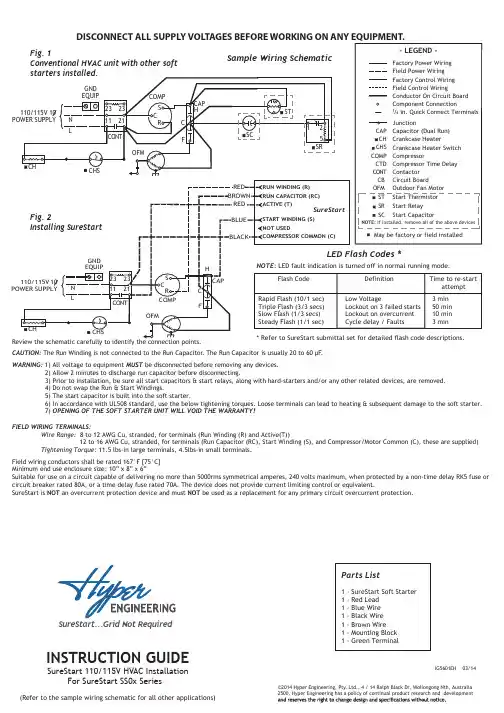
INSTRUCTION GUIDE SureStart 110/115V HVAC InstallationFor SureStart SS0x Series(Refer to the sample wiring schematic for all other applications)©2014 Hyper Engineering, Pty. Ltd., 4 / 14 Ralph Black Dr, Wollongong Nth, Australia 2500. Hyper Engineering has a policy of continual product research and developmentIG5601EH 03/14Parts List1 - SureStart Soft Starter1 - Red Lead1 - Blue Wire1 - Black Wire1 - Brown WireCAUTION: The Run Winding is not connected to the Run Capacitor. The Run Capacitor is usually 20 to 60 µF.WARNING:1) All voltage to equipment MUST be disconnected before removing any devices.2) Allow 2 minutes to discharge run capacitor before disconnecting.3) Prior to installation, be sure all start capacitors & start relays, along with hard-starters and/or any other related devices, are removed.4) Do not swap the Run & Start Windings.5) The start capacitor is built into the soft starter.6) In accordance with UL508 standard, use the below tightening torques. Loose terminals can lead to heating & subsequent damage to the soft starter.7) OPENING OF THE SOFT STARTER UNIT WILL VOID THE WARRANTY!FIELD WIRING TERMINALS:Wire Range: 8 to 12 AWG Cu, stranded, for terminals (Run Winding (R) and Active(T))12 to 16 AWG Cu, stranded, for terminals (Run Capacitor (RC), Start Winding (S), and Compressor/Motor Common (C), these are supplied)Tightening Torque: 11.5 lbs-in large terminals, 4.5lbs-in small terminals.Field wiring conductors shall be rated 167°F [75°C]Minimum end use enclosure size: 10” x 8” x 6”Suitable for use on a circuit capable of delivering no more than 5000rms symmetrical amperes, 240 volts maximum, when protected by a non-time delay RK5 fuse or circuit breaker rated 80A, or a time delay fuse rated 70A. The device does not provide current limiting control or equivalent.SureStart is NOT an overcurrent protection device and must NOT be used as a replacement for any primary circuit overcurrent protection.1 - Mounting Block1 - Green Terminal1) Disconnect all voltage to the HVACequipment.2) Secure the base for the SureStart inside control box.3) Remove the compressor RUN WIRE from the contactor or RUN CAPACITOR TERMINAL, as applicable.4) Strip the compressor RUN WIRE atleast 1/2 in.5) Attach the compressor RUN WIRE to the SureStart RUN WINDINGterminal.6) A ttach the BROWN WIRE supplied with the SureStart to the RUN CAPACITOR TERMINALon the Sure-Start.7) Identify the cable connecting the contactor and the RUN CAP . Remove the connection to the RUN CAP .Attach the flagged end of the BROWN WIRE the same terminal of the**(This is the Common (C) terminal for Dual Compressor/Fan Capacitors.)8) Attach the BLACK WIRE (supplied)to COMPRESSOR COMMON on the SureStart GREEN TERMINAL CONNECTOR .9)Attach the flagged end of the BLACK WIRE to the COMPRESSOR COMMON on the “T” side of the contactor.10) Attach the BLUE WIRE (supplied) to the START WINDING on the SureStart GREEN TERMINAL CONNECTOR .T ypical HVAC Application11)Attach the flagged end of the BLUE WIRE to the other terminal of the RUN CAPACITOR . Ensure that this terminal on the capacitor also joins to the START WINDING of the compressor. (This is the Herm (H)terminal for Dual Compressor/Fan Capacitors.)13)14) Apply power to the equipment and cycle to ensure proper operation.12) Attach the RED WIRE (supplied) to the ACTIVE TERMINAL on the SureStart.NOTE: The SureStart device could take up to six (6) starts to optimize performance.In accordance with UL508standard, use the following torque settings:11.5lbs-in large terminals 4.5lbs-in small terminalsRemove the loose wire (from step 7)from the ACTIVE input of the contactor and attach the stripped end of the ACTIVE WIRE in its place.。
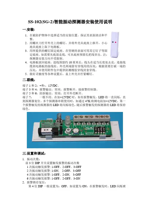
SS-102(SG-2)智能振动探测器安装使用说明一.安装:1.在被防护物体中选择适当的安装位置,保证其表面清洁和平整。
2.用螺丝刀拧开外壳上的螺钉,并将外壳从底座上移开,小心地从底座上取下电路板。
3.用所提供的螺钉固定底座。
在坚硬的表面可用其它钉子等固定底座。
如需要从底部走线,可从底座预留孔把线穿出。
注:探测器安装方向不受限制。
4.电路板放回底座,进线预留约10厘米长,线头在适当长度处去皮,连接线缆到电路板的接线柱。
外壳两端留有穿线用的压坑,根据需要打破一端的压坑,并使用附件包中提供防潮橡胶穿线封套穿线。
5.做好灵敏度等各种设置后,盖上外壳并拧紧螺钉。
二.联线:端子1和2:+和-,12VDC。
端子3和4:报警输出,常闭,报警断开,接报警控制器。
端子5和6:防拆输出,常闭,打开外壳断开。
端子7:一般不用。
在加+12VDC时,如有报警触发,LED将一直闪烁,直到探测器复位。
多个探测器串联使用时,如通过47K欧姆电阻加+12VDC,第一个报警触发的探测器的LED将闪烁绿色,随后报警触发的探测器的LED将保持绿色。
三.设置和调试:1.振动次数:前3位DIP开关设置触发报警的振动次数1次振动触发报警: 1-OFF,2-OFF,3-OFF2次振动触发报警: 1-ON, 2-OFF,3-OFF4次振动触发报警: 1-OFF,2-ON, 3-OFF6次振动触发报警: 1-OFF,2-OFF,3-ON2.报警锁存复位:第4位DIP一般设置为:OFF。
如设置为ON:在报警触发时,LED闪烁琥珀色,直到+12VDC电源断开后熄灭。
3.高低灵敏度档选择:1)选择高灵敏档:连接黑色跳线短路子(出厂设置);选择低灵敏档:拔掉黑色跳线短路子。
2)调整探测灵敏度:使用螺丝刀调整DIP开关旁的旋纽,逆时针旋转到MIN,灵敏度最低;顺时针旋转到MAX,灵敏度最高。
4.LED指示说明:红灯亮:探测到振动,但没有达到报警条件;绿灯亮:达到报警条件,报警继电器动作。

用途:本产品适用于家庭、小区、仓库、银行、企事业单位及商业场所。
不但功能强大、性能稳定,且操作和安装非常简单。
一、99防区语音防盗报警系统的组成与使用方法布防、撤防平时主人在家时可按遥控器的“撤防”键撤防,主人离家外出锁好门后,按遥控器“布防”键设防,回家时先按遥控器“撤防”键撤防,开锁进门。
在晚上主人在家休息时,按“S”键,这时主机进入红外撤防状态,在这种状态下学习进红外防区的探测器被触发不报警。
(相当于关掉了红外防区)。
在主机上布防与撤防、红外撤防及定时布撤防:布防:按“设防键”,再按"9”;撤防:按“设防键”,再按“0”;xx撤防:按主机的“设防键”,再按8定时布防:按主机的设防键,再按1,再按小时数(00-23),再按分钟数(00-59),再按#键。
例:要设2小时30分钟后布防:按主机设防键,再按1,再按0230#定时撤防:按主机的设防键,再按2,再按小时数(00-23),再按分钟数(00-59),再按#键。
例:要设9小时速50分后撤防:按主机设防键,再按2,再按0950#定时布防查询:按主机设防键,再按1,再按*键。
定时撤防查询:按主机设防键,再按2,再按*键。
注:如果开启主机密码键盘保护功能时,要先输入密码才能对主机的键盘进行操作。
紧急报警功能:当有紧急情况时,按下遥控器的:“紧急”键,系统立即进入紧急报警状态,警号鸣响并自动拨号呼叫。
或按主机的设防键,再按*键,系统立即进入紧急报警状态。
二、99防区语音防盗报警系统的系统设置接到报警后的处理方法:当警情发生后,主机会自动抢线拨打设置的电话号码,并根据设置鸣响警笛并语音提示报警的防区号,如果主人电话占线或不能接通,系统会转拨下一个报警电话,系统循环拨打三遍预设的电话号码。
收到报警电话后播放录音,用户可以不需要输入密码,按电话上的数字键对报警器进行远程控制。
如果20秒无按键操作,主机将会自动挂机退出。
1:布防2:撤防5:鸣响警号6:关闭警号7:打开现场监听8:关闭现场监听9:退出设置并挂机(如果不按“9”号键就挂机,系统会自动拨打下一组电话号码)远程控制操作方法:远程控制操作方法可使用任何电话拨打主机所接报警器的号码,系统检测到你所设置的响铃次数后,会自动接通,听到提示音后,输入密码(主机出厂的密码为“1234”,密码错误会自动挂机),正确输入密码后可按电话上的数字键对系统进行远程控制。
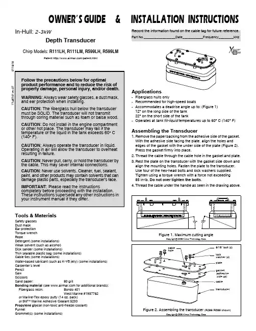
Follow the precautions below for optimalproduct performance and to reduce the risk of property damage, personal injury, and/or death.WARNING : Always wear safety glasses, a dust mask, and ear protection when installing.CAUTION : The fiberglass hull below the transducer must be SOLID. The transducer will not transmit through coring material such as foam or balsa wood.CAUTION : Do not install in the engine compartment or other hot place. The transducer may fail if the temperature of the liquid in the tank exceeds 60° C (140° F).CAUTION : Always operate the transducer in liquid. Operating in air will allow the transducer to overheat resulting in failure.CAUTION : Never pull, carry, or hold the transducer by the cable. This may sever internal connections.CAUTION : Never use solvents. Cleaner, fuel, sealant, paint, and other products may contain solvents that can damage plastic parts, especially the transducer’s face.IMPORTANT : Please read the instructionscompletely before proceeding with the installation. These instructions supersede any other instructions in your instrument manual if they differ.17-467-01 r e v .0707/19/18In-Hull: 2-3kWDepth TransducerChirp Models: R111LH, R111LM, R599LH, R599LMPatent /patent.htmlTools & MaterialsSafety glasses Dust mask Ear protection Torque wrench RopeDetergent (some installations)Weak solvent (such as alcohol)Disk sander (some installations)Thin sealable plastic bag (some installations)Cable ties (some installations)Water-based lubricant (such as K-Y ® jelly) (some installations)Carpenter’s level Pencil Saw Scissors Sand paper:80 gritBonding material (see for additional brands):Fiberglass resin:Bondo 401West Marine #1937762or Marine-Tex epoxy putty (14 oz. pack)or 3M™ Marine Adhesive/Sealant 5200Propylene glycol (non-toxic anti-freeze/coolant)FunnelGrommet(s) (some installations)Applications•Fiberglass hulls only•Recommended for high-speed boats•Accommodates a deadrise angle up to: (Figure 1)12° on the long side of the tank 22° on the short side of the tank•Operates at tank fill-liquid temperatures up to 60° C (140° F)Assembling the Transducer1.Remove the paper backing from the adhesive side of the gasket. With the adhesive side facing the plate, align the holes and edges of the gasket with the under side of the plate (Figure 2). Press the gasket firmly into place.2.Thread the cable through the cable hole in the gasket and plate.3.Rest the plate on the transducer with the gasket side down and align the mounting holes. Fasten the plate to the transducer. Use four of the hex-head bolts and lock washers supplied. Tighten using a torque wrench with a force not exceeding 85 in-lb. Do not over tighten the bolts .4.Thread the cable under the handle as seen in the drawing above.Figure 2. Assembling the transducer (R299/R399 shown)Record the information found on the cable tag for future reference.Part No._________________Date___________Frequency________kHz9/16" bolt (4)locktransducergasket plate cable cable (adhesive side up)Copyright © 2006 Airmar Technology Corp.washer (4)holeFigure 1. Maximum cutting angleCopyright © 2006 Airmar Technology Corp.12°22°OWNER’S GUIDE & I NSTALLATION INSTRUCTIONSMounting LocationAbout Fiberglass HullsSince the hull absorbs acoustic energy, transmitting through the hull reduces the transducer’s performance. Fiberglass hulls are often cored in places for added strength or to reduce weight. These cored areas contain balsa wood or structural foam which are poor sound conductor s. Do not locate the transducer over coring.Choose a Location•Where the fiberglass is SOLID (no air bubbles are trapped in the fiberglass resin) and where no coring, flotation material, or dead air space is sandwiched between the inside skin and outer skin of the hull.•Where the hull below the transducer will be in contact with the water at all times.•Where the water flowing under the hull is smoothest with a min-imum of bubbles and turbulence (especially at high speeds). Do not mount the transducer in line with or near water intake or dis-charge openings; or behind strakes, fittings, or hull irregularities that will disturb the water flow.•Where the transducer beam will not be blocked by the keel or propeller shaft(s).•Away from interference caused by power and radiation sources such as: the propeller(s) and shaft(s), other machinery, other echosounders, and other cables. The lower the noise level, the higher the echosounder gain setting that can be used.•Where the deadrise angle does not exceed either 12° on the long side of the tank or 22° on the short side of the tank.•Where there is space inside the vessel for the size of the tank and removing the transducer.•Mount in a cool well-ventilated area away from the engine to avoid overheating the liquid inside the tank.Boat Types(Figure 3)•Displacement hull powerboats—Locate amidships near the centerline. The side of the hull where the propeller blades are moving downward is preferred.•Planing hull powerboats—Mount well aft, on or near the centerline, and well inboard of the first set of lifting strakes to ensure that the transducer will be in contact with the water at high speeds. The side of the hull where the propeller blades are moving downward is preferred.Outboard and I/O—Mount just forward of the engine(s). Inboard—Mount well ahead of the propeller(s) and shaft(s). Stepped hull—Mount just ahead of the first step.Testing the Selected Mounting Location Establishing a Performance BaselineThe results of this test are used as a basis of comparison to determine the best in-hull location for the transducer.1.Take the boat to the maximum depth in which you will be operating the echosounder. If deep water is not available, find a location with at least 30m (100').2.Connect the transducer to the echosounder.3.Tie a rope securely around the handles of the transducer (Figure 4). Lower it over the side of the boat until the active face is fully submerged and parallel to the water surface.4.Observe the echosounder’s performance and the depth reading. Testing the LocationWhile the boat is at the same site (depth of water), test the transducer inside the hull at the mounting location. Use one of the test methods below:A.If the transducer will be located near the stern and the boat has a minimum deadrise angle—Clean away any build-up of dirt and/or grease using detergent or a weak solvent such as alcohol. Place the transducer against the hull and allow bilge water to cover the surface where they touch (Figure 5-A).B.For a moderate deadrise angle—If the hull surface is not smooth, grind it with a disc sander. Place the transducer inside a thin plastic bag. Partially fill the bag with water and close it tightly with a cable tie. Wet the surface of the hull and press the active face of the transducer against it through the bag (Figure 5-B).Figure 4. Establishing a performance baselineactive face2Copyright © 2006 Airmar Technology Corp.C.For any location —If the hull surface is not smooth, grind it with a disc sander. Coat the active face of the transducer with a water-based lubricant (such as K-Y ® jelly). With a twistingmotion, press the face firmly against the hull (Figure 5-C). After testing, wipe away all traces of the lubricant from the transducer’s face.Observe the echosounder’s performance and compare it to the baseline. Look for a stable depth reading that is similar to the baseline. Compare the thickness and intensity of the bottom trace.If the performance is close to the baseline, this is a good mounting location. Remember, some energy is lost transmitting through the hull. If the test reading differs markedly from the baseline, you will need to find another location to install the transducer.NOTE : If there is no reading or it is erratic, the transducer may be positioned over coring which is absorbing the acoustic energy. Choose another location. If no other location is available, check with the boat manufacturer to be certain coring is present.InstallationMarking & CuttingCAUTION : For optimal performance, the transducer must be installed so the beam will be aimed straight down. This isaccomplished by cutting the tank to match the deadrise angle of the hull.CAUTION : Do not mark or cut the tank in the space labeled “Do not cut above this line.”1.When you are satisfied that the selected mounting location is optimal, place the tank up-side-down on the hull (Figure 6).NOTE : The tank can be placed with either a short side or long side parallel to the centerline of the boat.2.Holding a carpenter’s level even with the lower corner of one of the sides to be cut, draw a level line on the tank. Repeat this process on the opposite side of the tank. Connect these two lines to form the SHORTEST side of the tank. Be sure the lines are level, as they will be the cutting guidelines.3.Before cutting the tank, be sure the TALLEST side will be closest to the centerline (keel) of the boat after the tank is installed . And be sure to observe the “Do not cut above this line” ing a saw, cut the three sides of the tank along the guidelines drawn. It may be necessary to further shape the tank to the hull to ensure a liquid-tight bond.4.The tank is provided with a cork liner to reduce sound echoes. After the tank has been cut, wrap the cork liner around theinside of the tank (Figure 7). Butt the sides of the liner along the center of the tallest side. Trace the bottom edge of the tank onto the liner.NOTE : There may be a gap between the butted edges which will not affect performance.5.Remove the cork liner from the tank. Use scissors to cut the liner along the line drawn.Figure 5. Testing the transducer at the selected locationA B CFigure 7. Fitting the cork liner (22° angle shown)Figure 6. Marking the cutting guidelinesstarting at the top hullof tankcarpenter’s lower corner.levelDraw a level line 3Copyright © 2006 Airmar Technology Corp.Copyright © 2006 Airmar Technology Corp.Copyright © 2006 - 2011 Airmar Technology Corp.Do not mark below this line.trace bottom edge of tank onto cork linerpossible gapBonding the TankCAUTION: The tank must be liquid-tight. To ensure a tight bond, the hull surface under and around the tank must be smooth, free of paint or any other finish, clean, and dry.1.To ensure a tight bond, remove any paint or other hull finish. If the surface is rough, use a disk sander to smooth an area slightly larger than the tank. Clean any dust, grease, or oil from the hull surface with a weak solvent, such as alcohol. Dry the effected area.e 80 grit sand paper to sand the outside and inside of the tank up 50mm (2") above the bottom edge. Remove the dust with a weak solvent, such as alcohol. Dry the effected area.e an approved bonding material (see Tools & Materials on page 1). Glass the tank to the hull with fiberglass resin, using standard fiberglass technique. Alternatively, apply a generous bead of marine putty/sealant to the bottom edge of the tank following the manufacturer’s instructions (Figure 8). Press the tank firmly in place. Apply a second bead around the inside of the tank. And apply a third bead around the outside of the tank.4.Allow the bonding material to cure. The seal must be liquid-tight. Installing the TransducerCAUTION: Do not use sealant or adhesive on the gasket. To do so may break the tank when the transducer is removed. CAUTION: Do not over tighten the bolts to avoid cracking the tank.1.After the bonding material has cured, insert the cork liner into the tank (Figure 8). Butt the edges along the center of the tallest side. Note, there may be a gap, but this will not affect performance.2.Following the manufacturer’s directions for use, pour propylene glycol into the tank until it covers the exposed hull.3.Before installing the transducer, wipe it clean of any lubricant that was used in testing the location.4.Grasp the transducer by the handles and lower it into the tank. There is no fore or aft to the transducer; it fits either way.5.Attach the transducer to the tank. Use the six remaining 9/16" hex-head bolts and six lock washers supplied. Tighten using a torque wrench with a force not exceeding 85 in-lb. Do not over tighten.6.Top-off the propylene glycol in the tank. However, allow a small air space to accommodate expansion with temperature changes. Using a funnel, pour the fill-liquid through one of the fill/vent holes until the tank is full. The second hole will act as a vent. Plug both holes with the vent plugs supplied.Cable Routing & ConnectingCAUTION: If the transducer came with a connector, do not remove it to ease cable routing. If the cable must be cut and spliced, use Airmar’s splash-proof Junction Box No. 33-035 and follow the instructions supplied. Removing the water-proof connector or cutting the cable, except when using a water-tight junction box, will void the transducer warranty.1.Route the cable to the echosounder being careful not to tear the cable jacket when passing it through the bulkhead(s) and other parts of the boat. Use grommets to prevent chafing. To reduce electrical interference, separate the transducer cable from other electrical wiring and the engine(s). Coil any excess cable and secure it in place with cable ties to prevent damage.2.Refer to your echosounder owner’s manual to connect the transducer to the instrument.OperationMonitor the transducer ID line for the internal temperature of the fill liquid within the tank. The transducer may fail if the fill-liquid reaches temperatures above 60° C (140° F). Replacement Transducer & PartsThe information needed to order a replacement Airmar transducer is printed on the cable tag. Do not remove this tag. When ordering, specify the part number, date, and frequency in kHz. For con-venient reference, record this information at the top of page one. Lost, broken, or worn parts should be replaced immediately. Obtain parts from your instrument manufacturer or marine dealer. Gemeco USATel: 803-693-0777email:**************** Airmar EMEA Europe, Middle East, AfricaTel: +33.(0)2.23.52.06.48email:********************* Figure 8. Cross section of installed transducergasketfiberglasspropylene glycolhullin placeor applythree beadsof marinecork liner4Copyright © 2003 - 2018 All rights reserved.(non-toxic antifreeze/coolant)Copyright © 2006 Airmar Technology Corp.fill/vent plug (2)putty/sealanttransducer35 Meadowbrook Drive, Milford, New Hampshire03055-4613, USA•。

Cautions for proper and safeoperation. To use this productsafely, please read this instructionmanual carefully. Incorrect operationmay cause malfunction, damageor accident. The cautions andwarnings in the document areindicated by the following:WARNING: I ndicates that incorrect use may result inservice injury or loss of life.CAUTION: I ndicates that incorrect use may result inservice injury or property damage.WARNING:1. Do not apply pressure greater than the maximumallowable pressure. This may cause damage or rupturethe pressure element, resulting in injury or damage to the surroundings.2. Do not use this product to measure the fluid which causesgas/liquid contact area to corrode. This may cause dam-age or rupture the pressure element, resulting in injury or damage to the surroundings.3. Do not apply excessive weight, vibration or shock. Thismay cause damage or rupture the pressure element, result-ing in injury or damage to the surroundings.4. Use of a non-designated power source may cause fires orelectric shocks.5. Use this device within the operating temperature range.Using the instrument outside of the recommended operat-ing temperature range may cause malfunction or damage and result in injury or damage to the surroundings.6. Perform wire connection according to the wire connectionfaceplate or the wire connection instructions within theinstruction manual. Incorrect wiring may cause injury or fire.7. Use explosion-proof product when required or explosivegas exists; this is due to the potential of ignition or explosion.8. Use instruments that have been properly cleaned and arefree of oil when the process media is oxygen. Standard(uncleaned) product may contain oil; contact with oxygen can result inignition and/or explosive reactions.9. Perform installation according to the instruction manual.10. D o not alter this product in any manner or form. In addi-tion, do not disassemble this product. Contact Ashcroft for repairs.11. S ince this product is a precision measuring instrument, itis advised that the product be removed from all sourcesof noise. Remove noise from the power source by usingnoise filter, etc.Table of contents:1. INTRODUCTION (2)2. ATTENTION (2)3. GENERAL DESCRIPTION (2)4. OUTLINE DRAWINGS (Representative example) (2)5. PRECAUTIONS FOR USE5-1. Transportation precautions (3)5-2. Unpacking precautions (3)5-3. Mounting precautions (3)5-4. Storage precautions (4)6. WIRING6-1. Examples of wire connection & external connection ..4 6-2. Load resistance (4)6-3. Specifications of the cable with M12 connector(optional) (5)7. PRINCIPLE OF OPERATION (5)8. ZERO AND SPAN CALIBRATION (5)9. MAINTENANCE AND OPERATION9-1. Maintenance (5)9-2. Adjustment (6)10. WARRANTY (7)11. OTHERS (7)1. INTRODUCTIONPlease double-check the specifications for the model that you have received.If specifications such as the pressure range, power source,or output are incorrect, accidents can occur. Please be sure to use a model that is appropriate for your specifications, in a location which is appropriate for your usage environment, and which has been correctly wired and installed.2. ATTENTIONAshcroft shall have no liability for failure, product issue, or physical injury resulting from the following:• M odification and repair performed by any non-Ashcoft personnel.• P roduct issue caused by product of another company• M isuse of product instructions, instrument operation and/or not observing conditons/methods stipulated within the instruction manual.• N atural disasters, such as fire, seismic activity, water/flood damage, lightning, etc.3. GENERAL DESCRIPTIONThis is a pressure transmitter developed for the semiconductor industry. In contrast to conventional transmitters, this product offers a compact and lightweight design. Pressure is converted into electric signals and transmitted by the sensing portion equipped with strain gauges and a built-in electronic circuit. 4. O UTLINE DRAWINGS: ZT11 Male Flow-Through OUTLINE DRAWINGS: ZT11 Female Swivel OUTLINE DRAWINGS: ZT11 Male Swivel[25][20] 0.18 [4.5][25]Ø 0.79 [20] 0.18 [4.5]OUTLINE DRAWINGS: ZT11 Male Fixed5. P RECAUTIONS FOR USE 5.1 Transportation PrecautionsCAUTION:T his is a precision measuring instrument. Do not drop or impact when transporting asshock may cause damage and render the instrument inoperable.5.2 Unpacking Precautions• C heck packaging appearance prior tounpacking.• C arefully handle and do not drop unit carton.CAUTION:• O pen instrument’s sealed bag in a clean environment. Do not expose PressureTransmitter’s gas contact parts to moisture, dust, etc.• U pon unpacking, inspect unit to verify that the model type and physical appearance are correct and free from damage.• C ontact distributor or Ashcroft if any abnormality has been identified with the product.5.3 Installation Precautions (1) Z T11 pressure transmitter is equipped with a unionconnection that is compatible with a ¼ VCR ® fitting (9/16-18 UNF). For installation, make sure to use hexagonal flats to tighten fitting. Do apply force to the unit enclosure when attached to the pressure line.(2) This product has protection class IP67 (connector mat-ing state/JIS C 0920).For longer-term operation, select a location that is notexposed to direct sunlight, condensation, dust, oil or water. In addition, please pay particular attention to the following during installation . • Do not drop or impact unit as shock may render unit inoperable.• Do not install product in an environment exposed to vibration, impact, direct sunlight or dust.• Use product in ambient temperaturesbetween -° to 158 °F (-20 to 70 °C) • Allow for space around the instrument for maintenance and adjustment.• Do not touch or breathe on the gas contact parts, while taking care not to damage theIndicates that incorrect use may result in service injury or loss of life.seat surface. CAUTION: • Do not apply excessive force to theenclosure during installation.WARNING: • Take care not to block the air inlet on thetop of the instrument (Refer to “5. Outline drawings”). Unit will not provide prescribed performance if the air inlet is obstructed/blocked.• Do not apply excessive force or excessive bending to the cable once the connector is attached to the product and the mating connector.• Snoop test of the sensor part should be avoided as this may cause an insulation resistance defect.• Prior to commencing operation, it is recommended to purge the unit with sufficient inert gas. This will remove any atmospheric component, particles, and/orforeign matter within the pipe[25][20]0.18[4.5]5.4 Storage Precautions • T o avoid failure or damage, do not store product under the following conditions: • Do not expose to water• Susceptible to adverse effects due to air pressure, temperature, humidity, ventilation,sunlight, particles, salt or sulfur in the air CAUTION: • D o not expose to inclination, vibration orshock (including during transportation)• D o not expose to chemicals (chemicals’ storage area) or gas• Do not expose to direct sunlight or high temperature• D eformation and discoloration of resin parts may occur when product is stored in asealed bag under high temperature and high humidity environments.6. WIRING6.1 Wiring schematic of mating connectorWire connection and external connection should be carriedout as follows.Insert the cable with M12 connector (optional) while aligning to the connector groove on the instrument.Hand-tighten until the nut does not move. [Tightening torque: 0.4 to 0.5N •m]6.2 Load ResistanceRefer to the following chart for relationship between load resistance and power supply voltage.Maximum load resistance R Lmax Minimum load resistance R LminE (V)-10(V)0.02(A)E (V)-26.4(V) 0.02(A)(Ω),R Lmin ≥o(Ω)• P roduct protection class IP67 may beimpaired if the tightening nut for the cable to the M12 connector (optional) proves insuffi-cient. Be sure to tighten securely to counter possible vibration; tightening torque: 3.54 to 4.43 in. lb.Do not not perform any wiring procedures when powering the unit.6.3 S pecifications of the cable with M-12 connector(optional)If using a connector that has not been supplied by Ashcroft, please make sure your connector meets the following specifications.• The cable is comprised of a 4-wire systemCAUTION: (white, black, blue, brown), however, the white and black wires are not used.7. Principle of OperationThe transmitter’s sensing diaphragm converts pressure to an electrical signal by use of strain gages. The circuit is a full-bridge system where the strain gages are positioned on all four bridge sides and detect the amount of strain. An electrical signal, in proportion to the strain amount, is then amplified to a specific value by the electrical circuit and transmitted as direct current output.(1) Z inc die-casting (nickel-plated)(2) TPU (Green)(3) PUR)(1)S tainless (2) TPU (Black)(3) PVC)2 m or 5 m 2 m or 5 m 0.34 mm 2 (22 AWG)or higher in a mating state.Block diagram (4 to 20 mA DC/2-wire system)8. Zero and Span Calibration 1) P rior to powering the unit, double-check to make sure all wires have been properly connected. Verify that voltage and amperage ratings of the power supply and internal resistance of the external adaptation equipment are within the rated range of the instrument’s load resistance. Lastly, re-confirm that the pressure transmitter has been installed within an operating environment that complies with the explosion-proof specification.(2) Z ero adjustment can be performed once the unit has been powered for a 15-minute warm-up period. Zero adjustment can be performed by removing the rubber plug located at the top of the enclosure. Refer to “9-2. Adjustment” (below) to adjust properly. Observe the following precautions while operating:• D o not apply any pressure above that refer-enced on the product’s label.• D o not adjust wiring or insert/remove the connect or while the device is powered, asthis may damage the device and/or causean electric shock. All wiring should be con-nected in accordance to the product wiring diagrams.• I f used with corrosive gas, it is highly recommended that the pressure transmitter be fully purged with nitrogen gas prior to being removed for maintenance or other servicing. Leaving corrosive gas within a device will accelerate corrosion by forming strong acid or alkaline substance generated internally by moisture or oxygen within the atmosphere.9. Maintenance and Adjustment9.1 MaintenaceRoutine inspection should be conducted at least once every 6 months with device recalibration or zero adjustment being performed as necessary. Product should only be inspected by properly trained personnel.CAUTION:WARNING:• T he rubber plug is equipped with simpleanti-falling function, however if it is pulled CAUTION:strongly, the function is impaired. Please becareful not to pull too much more than nec-essary [<17 in. lb.].The “Z” on the rubber plug indicates the position of the potentiometer for Zero adjustment, and the “S” indicates the position of the potentiometer for Span adjustment.a. A djust the zero point output in the same way as [(1) Zeroadjustment].b. A ccurately apply pressure upper limit in the pressure range, and then adjust the output to 20 mA DC in span adjustment potentiometer.c. R epeat several times alternating Step a and b to make the span adjustment.• D o not change zero adjustment while rotat-ing span adjustment potentiometer.• A void putting an excessive load, >44 in. lb.,10 sec., on the zero/span adjustment poten-tiometers as this may result in damage.• D o not apply pressure above the pressurerange indicated on the device label.After the adjustment, please be sure to attach the rubber plug by referring to the figure below.The “Z” on the rubber plug indicates the position of the poten-tiometer for zero adjustment, and the “S” indicates the posi-tion of the potentiometer for span adjustment.• E nsure rubber plug has been returned to its original position to retain product pro-tection class integrity. Protection class maybe impaired if the rubber plug is not firmly affixed.10. WARRANTYIf the delivered products within the warranty period (within one year from the delivered date) are determined to be non-con-forming products according to “Defects due to the design or manufacturing”, they are repaired or replaced with conforming products free of charge.However, note that the following cases are excluded.(1) W here the delivered products are disassembled, altered or where their parts are replaced or new function is add by the customer or any third party(2) W here directions described in the instruction manual orcatalog are not observed.(3) W here the non-conformance is caused by deterioration due to use, natural disaster, fire or other force majeure events (4) T he secondary damage caused by non-conformance of the products including the above.Returned units are subject to evaluation by Ashcroft prior to determining warranty. 11. OTHERSThis instruction manual is not intended to cover all equipment and/or installation and maintenance details. Please contact Ashcroft if additional detail is sought, or in the event that the instrument does not adequately serve your company’s intentions.Additionally, this instruction manual may be changed, at any time, without prior notice for the purposes of version upgrades, revisions etc.Thank you for your understanding and cooperation.CAUTION:CAUTION:。
Bulletin L-UTTable of ContentsChapter 1. Introducing Series UTSensor Dimensions . . . . . . . . . . . . . . . . . . . . . . . . . . . . . . . . . . . . . . . . . . . . . . . .2 Series UTC Specifications . . . . . . . . . . . . . . . . . . . . . . . . . . . . . . . . . . . . . . . . . . .2 Series UTS Specifications . . . . . . . . . . . . . . . . . . . . . . . . . . . . . . . . . . . . . . . . . . .2 Sensor Recommendations . . . . . . . . . . . . . . . . . . . . . . . . . . . . . . . . . . . . . . . . . .2 Sensor Cable Recommendations . . . . . . . . . . . . . . . . . . . . . . . . . . . . . . . . . . . . .2 Chapter 2. Installing Series UTPrecautions . . . . . . . . . . . . . . . . . . . . . . . . . . . . . . . . . . . . . . . . . . . . . . . . . . . . . .3 Installing the Series UT Sensor . . . . . . . . . . . . . . . . . . . . . . . . . . . . . . . . . . . . . . .3 Threading Options . . . . . . . . . . . . . . . . . . . . . . . . . . . . . . . . . . . . . . . . . . . . . .4 Sensor Positioning . . . . . . . . . . . . . . . . . . . . . . . . . . . . . . . . . . . . . . . . . . . . . .4 Installing the Sensor via an Extension Pipe . . . . . . . . . . . . . . . . . . . . . . . . . .4 Wiring the Series UT Unit . . . . . . . . . . . . . . . . . . . . . . . . . . . . . . . . . . . . . . . . . . .3 Wiring the Sensor Cable . . . . . . . . . . . . . . . . . . . . . . . . . . . . . . . . . . . . . . . . .4 Wiring the Monitoring Cables . . . . . . . . . . . . . . . . . . . . . . . . . . . . . . . . . . . . . .4 Wiring the Relays Cable . . . . . . . . . . . . . . . . . . . . . . . . . . . . . . . . . . . . . . . . .4 Wiring VDC Power Cable . . . . . . . . . . . . . . . . . . . . . . . . . . . . . . . . . . . . . . . . .4 Wiring VAC Power Cable . . . . . . . . . . . . . . . . . . . . . . . . . . . . . . . . . . . . . . . . .4 Series UT Intrinsically Safe Connections . . . . . . . . . . . . . . . . . . . . . . . . . . . . .4 Chapter 3. Basic Set UpUsing the Series UT Function Buttons . . . . . . . . . . . . . . . . . . . . . . . . . . . . . . . . .5 Modifying Numerical Values . . . . . . . . . . . . . . . . . . . . . . . . . . . . . . . . . . . . . . .5 Menu and Version Selection . . . . . . . . . . . . . . . . . . . . . . . . . . . . . . . . . . . . . . . . .6 Accessing the Main Menu . . . . . . . . . . . . . . . . . . . . . . . . . . . . . . . . . . . . . . . . . . .6 Using the Main Menu . . . . . . . . . . . . . . . . . . . . . . . . . . . . . . . . . . . . . . . . . . . .6 Default Screen . . . . . . . . . . . . . . . . . . . . . . . . . . . . . . . . . . . . . . . . . . . . . . . . . . . .7 Setting Main Menu Options . . . . . . . . . . . . . . . . . . . . . . . . . . . . . . . . . . . . . . . . . .7 Setting the Indication Mode . . . . . . . . . . . . . . . . . . . . . . . . . . . . . . . . . . . . . .8 Setting the Measurement Mode . . . . . . . . . . . . . . . . . . . . . . . . . . . . . . . . . . .8 Setting the Relay Values for Series UTC . . . . . . . . . . . . . . . . . . . . . . . . . . . . .8 Setting the Relay Values for Series UTS . . . . . . . . . . . . . . . . . . . . . . . . . . . . .9 Setting the 20 mA/4 mA Levels . . . . . . . . . . . . . . . . . . . . . . . . . . . . . . . . . . . .9 Setting the Flow Measurements . . . . . . . . . . . . . . . . . . . . . . . . . . . . . . . . . . .9 Setting the Tank Height . . . . . . . . . . . . . . . . . . . . . . . . . . . . . . . . . . . . . . . . . .9 Setting the Application Type . . . . . . . . . . . . . . . . . . . . . . . . . . . . . . . . . . . . . .10 Setting the Operation Modes . . . . . . . . . . . . . . . . . . . . . . . . . . . . . . . . . . . . . .9 Setting the Sensor Offset . . . . . . . . . . . . . . . . . . . . . . . . . . . . . . . . . . . . . . . . .9 Setting the Scan Distance Values . . . . . . . . . . . . . . . . . . . . . . . . . . . . . . . . . .9 Clearing the Scan Distance Values . . . . . . . . . . . . . . . . . . . . . . . . . . . . . . . .10 Viewing Processor Information . . . . . . . . . . . . . . . . . . . . . . . . . . . . . . . . . . . . . . .7 Chapter 4. Series UT Open ChannelsSelecting the Flow Measurement Settings . . . . . . . . . . . . . . . . . . . . . . . . . . . . .10 Open Channel Flow Measurements . . . . . . . . . . . . . . . . . . . . . . . . . . . . . . . . . .10 Flume/Weir Types . . . . . . . . . . . . . . . . . . . . . . . . . . . . . . . . . . . . . . . . . . . . . .11 European Standard . . . . . . . . . . . . . . . . . . . . . . . . . . . . . . . . . . . . . . . . . . . .11 Rectangular Suppressed Sharp - Crested Weir (Type 1) . . . . . . . . . . . . . . .11 Rectangular Contracted Sharp - Crested Weir (Type 2) . . . . . . . . . . . . . . . .11 Trapezoidal (Cipolletti) Sharp - Crested Weir (Type 3) . . . . . . . . . . . . . . . . .11 V-Notch (Triangular) Sharp - Crested Weir (Type 4) . . . . . . . . . . . . . . . . . . .11 Khafagi-Venturi Flume (Type 5) . . . . . . . . . . . . . . . . . . . . . . . . . . . . . . . . . . .12 Parshall Flume (Type 6) . . . . . . . . . . . . . . . . . . . . . . . . . . . . . . . . . . . . . . . . .12 Palmer Bowlus Flume Trapezoidal Throat Cross-Selection (Type 7) . . . . . .12H Flume (Type 8) . . . . . . . . . . . . . . . . . . . . . . . . . . . . . . . . . . . . . . . . . . . . . .12Neyrpic Venturi Flume/Long-Base Weir (Type 9) . . . . . . . . . . . . . . . . . . . . .13 American Standard . . . . . . . . . . . . . . . . . . . . . . . . . . . . . . . . . . . . . . . . . . . . .13 Rectangular Suppressed Sharp - Crested Weir (Type 1) . . . . . . . . . . . . . . .13 Rectangular Contracted Sharp - Crested Weir (Type 2) . . . . . . . . . . . . . . .13 Trapezoidal (Cipolletti) Sharp - Crested Weir (Type 3) . . . . . . . . . . . . . . . . .13 V-Notch (Triangular) Sharp - Crested Weir (Type 4) . . . . . . . . . . . . . . . . . . .13 Parshall Flume (Type 5) . . . . . . . . . . . . . . . . . . . . . . . . . . . . . . . . . . . . . . . .14 Palmer Bowlus Flume Trapezoidal Throat Cross-Selection (Type 6) . . . . . .14H Flume (Type 7) . . . . . . . . . . . . . . . . . . . . . . . . . . . . . . . . . . . . . . . . . . . . . .14Leopold-Lagco Flume (Type 8) . . . . . . . . . . . . . . . . . . . . . . . . . . . . . . . . . . .14 Chapter 5. Additional FeaturesAccessing the Additional Menu . . . . . . . . . . . . . . . . . . . . . . . . . . . . . . . . . . . . . .15 Setting Additional Menu Options . . . . . . . . . . . . . . . . . . . . . . . . . . . . . . . . . . . . .15 Selecting an Indication . . . . . . . . . . . . . . . . . . . . . . . . . . . . . . . . . . . . . . . . . .15 Manually Inserting Strapping Table Values . . . . . . . . . . . . . . . . . . . . . . . . . .15 Semi-automatic Inserting of Strapping Table Values . . . . . . . . . . . . . . . . . . .15 Inserting a Coefficient for Readings . . . . . . . . . . . . . . . . . . . . . . . . . . . . . . . .15 Erasing Strapping Table Values . . . . . . . . . . . . . . . . . . . . . . . . . . . . . . . . . . .15 Configuring Height for a Cone . . . . . . . . . . . . . . . . . . . . . . . . . . . . . . . . . . . .15Defining 22 mA/3.7 mA Signal Error Messages . . . . . . . . . . . . . . . . . . . . . .15 Entering Factor for Gas Compensation in Series UT . . . . . . . . . . . . . . . . . .15 Chapter 6. Troubleshooting Series UTAppendix A – Series UT Ranges . . . . . . . . . . . . . . . . . . . . . . . . . . . . . . . . . . . . .16 Appendix B – Gas Factor Table . . . . . . . . . . . . . . . . . . . . . . . . . . . . . . . . . . . . . .16 Index . . . . . . . . . . . . . . . . . . . . . . . . . . . . . . . . . . . . . . . . . . . . . . . . . . . . . . . . . . . .17 Table of FiguresFigure 1: Front View of Series UT . . . . . . . . . . . . . . . . . . . . . . . . . . . . . . . . . . . . . . .2 Figure 2: Side View of Series UT . . . . . . . . . . . . . . . . . . . . . . . . . . . . . . . . . . . . . . . .3 Figure 3: Wall Mount Plate . . . . . . . . . . . . . . . . . . . . . . . . . . . . . . . . . . . . . . . . . . . .4 Figure 4: Back View of Series UT with Wall-Mount Plate . . . . . . . . . . . . . . . . . . . . .4 Figure 5: Panel Mount . . . . . . . . . . . . . . . . . . . . . . . . . . . . . . . . . . . . . . . . . . . . . . . .4 Figure 6: Top View of Series UT with Panel-Mount Installation . . . . . . . . . . . . . . . . .4 Figure 7: Series UT Sensor Dimensions . . . . . . . . . . . . . . . . . . . . . . . . . . . . . . . . . .5 Figure 8: Sensor Threading Options . . . . . . . . . . . . . . . . . . . . . . . . . . . . . . . . . . . . .5 Figure 9: Sensor Positioning . . . . . . . . . . . . . . . . . . . . . . . . . . . . . . . . . . . . . . . . . . .6 Figure 10: Extension Pipe Installation . . . . . . . . . . . . . . . . . . . . . . . . . . . . . . . . . . . .8 Figure 11: Electrical Unit . . . . . . . . . . . . . . . . . . . . . . . . . . . . . . . . . . . . . . . . . . . . . .8 Figure 12: Series UT Main Menu Screen . . . . . . . . . . . . . . . . . . . . . . . . . . . . . . . . . .8 Figure 13: Series UT Default Screen . . . . . . . . . . . . . . . . . . . . . . . . . . . . . . . . . . . . .8 Figure 14: Tank Height . . . . . . . . . . . . . . . . . . . . . . . . . . . . . . . . . . . . . . . . . . . . . . . .8 Figure 15: Scan Distance Process . . . . . . . . . . . . . . . . . . . . . . . . . . . . . . . . . . . . . . .8 Figure 16: Rectangular Suppressed Sharp - Crested Weir . . . . . . . . . . . . . . . . . . .11 Figure 17: Rectangular Contracted Sharp - Crested Weir . . . . . . . . . . . . . . . . . . . .11 Figure 18: Trapezoidal (Cipolletti) Sharp - Crested Weir . . . . . . . . . . . . . . . . . . . . .11 Figure 19: V-Notch (Triangular) Sharp - Crested Weir . . . . . . . . . . . . . . . . . . . . . . .11 Figure 20: Khafagi-Venturi Flume . . . . . . . . . . . . . . . . . . . . . . . . . . . . . . . . . . . . . .12 Figure 21: Parshall Flume . . . . . . . . . . . . . . . . . . . . . . . . . . . . . . . . . . . . . . . . . . . .12 Figure 22: Palmer Bowlus Flume Trapezoidal ThroatCross-Selection . . . . . . . . . . . . . . . . . . . . . . . . . . . . . . . . . . . . . . . . . . .12 Figure 23: H Flume . . . . . . . . . . . . . . . . . . . . . . . . . . . . . . . . . . . . . . . . . . . . . . . . .12 Figure 24: Neyrpic Venture Flume . . . . . . . . . . . . . . . . . . . . . . . . . . . . . . . . . . . . . .13 Figure 25: Long-Base Weir . . . . . . . . . . . . . . . . . . . . . . . . . . . . . . . . . . . . . . . . . . .13 Figure 26: Leopold Lagco Flume . . . . . . . . . . . . . . . . . . . . . . . . . . . . . . . . . . . . . . .14 Figure 27: Cone Height . . . . . . . . . . . . . . . . . . . . . . . . . . . . . . . . . . . . . . . . . . . . . .14 Figure 28: Measuring Rolls Diameter . . . . . . . . . . . . . . . . . . . . . . . . . . . . . . . . . . .17Figure 5: Panel Mount (Contact Factory)1˝ BSP/1˝ NPTThreading for UTS-1XX-XXX-X (25 kHz) Sensor (Standard Range)1˝ BSP/1˝ NPTThreading for UTS-1XX-XXX-X (50 kHz) Sensor1˝ BSP/1˝ NPTThreading for UTS-1XX-2XX-X (25 kHz) Sensor(Long Range)2˝ BSP/2˝ NPTThreading for UTS-1XX-1XX-X (25 kHz) Sensor (Standard Range)• Mounted above the dead-zone area (Blind Zone)• Install the sensor as far as possible from noisy • The pipe extension is parallel to the side/tank• The tank should be empty to allow tracking of• The internal pipe diameter is at least 3˝ and 4˝extensionFigure 10: Figure 11: Electrial Unit Using Glands/ConduitsFigure 12: Series UT Main Menu ScreenThe digit currently available for modification is displayed flashing (flashing digits are shown in gray in the illustrations, for example, ). The value is modified by using the and buttons to move between the digits, and by using the and buttons to scroll through the possible number values for the flashing digit. If you press on the far left digit, you will revert either to the previous step of the function or to the main menu, without saving. If you press on the far right digit, the new buttons (Series UT) For more details, see page 8.current level of the tank contents, while the numerical area gives the exact reading.If the level enters the dead zone, the numerical area displays ; if the tank is empty, the numerical area displays the tank height. may be displayedDigit• Accessing the menus (when pressed simultaneously with ).• Accessing a function within a menu, enabling • Accessing the menus (when pressed simultaneously with ).• Moving from right to left between displayed digits orPress and simultaneously.seconds, then n is displayed.flashes for approximately 5ororFigure 13: Series UT Default ScreenThe following functions are available in the Series UT main menu.Refer to page 8.Refer to page 8.Refer to page 9.Refer to page 11. Refer to page 11. Refer to page 11. Refer to page 12. Refer to page 12. Refer to page 12. Refer to page 12. Refer to page 13.Press to savethe selected option.For example, orPress to savethe selected option.For example, orall five relays. The close value must be lower than the open value for each relay, otherwise an message is displayed. An message is displayed if a relay value is greater than the tank height value.by electronicinterference) relays will switch to Close state.to enter relaysetup.to assign anindication mode forto enter openmode.to enter valuesfor the relay.Press at the endof entering a valueandandandororvalue entered for a relay should be greater than value entered for the relay, otherwise an is displayed.mode shouldto enter relaysetup.to assign anindication mode.andFor example,orAs shown in the above example, relay values were configured in the following way:• - In case of lost echo or when measurement result is higher than • - Near dead zone.The relayorto select enableor disable mode.to select apulse value from theto enter a pulsewidth value (asororThe close value must be lower than the open value for each relay, otherwise an message is displayed.An message is displayed if a relay value is greater than the tank height value.by electronicinterference) relays will switch to Close state.The values of 4 in Appendix A, Series UT exceeds this maximum value, an error message is displayed.to enter relay setup.to enter open mode.Press on the far-right digit to save and andororThe values for 20 mA and 4 mA must be different, otherwise an message is displayed. Both must also be less than the tank height value, otherwise anmessage is displayed.to enter 20 mA or 4 mA setup.ororFigure 14: Tank Heightto save the selected option.for example.For example meters.ororandorFor example.ororororor PROCESSapplication mode, an warning message is displayed and SeriesUT reverts to distance mode. You must then reset the unit to flow mode.recommended for use as follows:• : Recommended in the following conditions:• Wavy surfaces• Applications where the sensor is installed near the tank wall•: (Twice as fast asRecommended in the following conditions:Figure 15: Scan Distance Process • : This mode is suitable for applications where a fast reading is moreEuropean open channel flow standard, and followed by the code value (YY ) that represents the appropriate flume/weir dimensions, in the following format: .codes are screen, pressandsimultaneously.andFor example,For example,Press/Action NOTES:If the indication at the base of the default display screen is lit, it might be a sign of acoustic display, pressand simultaneously.Press on the far right digit.For example,For example,ororororororFigure 11: Rectangular Suppressed Sharp-Crested WeirFigure 12: Rectangular Contracted Sharp-Crested WeirPalmer Bowlus Flume Trapezoidal Throat Cross-Selection (Type 7)1022.5Figure 14: V-Notch (Triangular) Sharp-Crested WeirFigure 15: Khafagi-Venturi FlumeFigure 16: Parshall FlumeCode (YY)0102Conduit Diameter (in) D68Figure 17: Palmer Bowlus Flume Trapezoidal Throat Cross-SelectionRectangular Contracted Sharp-Crested Weir (Type 2)Trapezoidal (Cipolletti) Sharp-Crested Weir (Type 3)Figure 18: H Flume091253FFigure 19: Neyrpic Venturi Flume131245DFigure 20: Long-Base WeirFigure 21: Rectangular Suppressed Sharp-Crested Weir0996.00Figure 22: Rectangular Contracted Sharp-Crested WeirCode (YY)010203Crest Length (in)12.0018.0024.00Code (YY)010203Crest Length (in)12.0018.0024.00Figure 24: V-Notch (Triangular) Sharp-Crested Weir16144 Figure 25: Parshall Flume Figure 26: Palmer Bowlus Flume Trapezoidal Throat Cross-SelectionFigure 27: H Flumetank graphic on the bottom right of the screen moves up from 0 to 100%. Thenumerical area then displays , enabling you to enter a new value forthe function. If an illegal option is selected, an error message is displayed while Figure 28: Leopold-Lagco Flume(after entering theUse or to change the display to , then press .flashes forapproximately 5seconds, thenflashes forapproximately 5seconds, thenis displayed.Use or to scrollthrough the additional menuoptions.ErrorPage 19©Copyright 2013 Dwyer Instruments, Inc.Printed in U.S.A. 6/13FR# R2-443909-00 Rev. 1。
FEATURES AND BENEFITSLONG-RANGE MONITORINGLongest range site detection for fence line/perimeter monitoring up to 330 meters (1082 feet).Flat response over a range of target gasses; performance approved.RELIABLE DETECTIONFast response to flammableHydrocarbon gas even in low visibility conditions. Advanced diagnosticsincluding window clarity and alignment accuracy to enable maximum uptime and continuous site protection.HEAVY DUTY OPERATIONOperates in harsh environments to maintain coverage. Advanced transmitter and receiver opticsmeans that monitoring continues in thick fog long after other detectors cease to provide coverage.AT-A-GLANCEINSTRUMENT STATUSHigh Visibility LED HALO ring provides clear indication of device status.Automatic reporting with full logging of alarms, events and maintenance actions.EASY TO USEHoneywell Fixed Platform Universal Mount and advanced alignment scope makes for easy mechanical installation. Incorporates Bluetooth® connectivity for simplified, non-intrusive set-up and maintenance. Just pair the Searchline Excel™ Edge with our intrinsically safe, ruggedized mobile phone; then use the Honeywell Fixed Platform App to interact with the detector.MULTIPLE OUTPUTSMultiple outputs including 4-20mA, Relays, HART®, Modbus and Bluetooth® communication.Easily integrate the Searchline Excel™ Edge into your existing network.APPROVALSGlobal hazardous area andperformance approvals include SIL2, ATEX, IECEx, cULus, FM, INMETRO, CCCF, Ex d, Zone 1, ClassII/III and ANSI/FM/IEC/EN60079-29-41.HONEYWELL SEARCHLINE EXCEL ™ EDGEPush your detection to the EdgeThe Searchline Excel™ Edge FlammableHydrocarbon gas detector delivers long-range coverage and protection for perimeter and fence-line monitoring.LONG-RANGE PERIMETER MONITORING IN HARSH CONDITIONSDesigned for long-range perimeter and fence line monitoring applications, the Searchline Excel™ Edge helps protect your people, facilities and processes from combustible gas leaks. When mounted at the edge/perimeter of your facility, it provides long-range monitoring and reliable detection in harsh and changing environments for protection and peace of mind.ELEVATE YOUR ENVIRONMENTAL DUE DILIGENCEThe Searchline Excel™ Edge’s innovative optical gas detection capabilities cover a longer range and see through even thick fog better than any other open path gas detectors whether NDIR or laser-based.Honeywell Searchline Excel TM Edge T echnical SpecificationsSee product manual for full specifications.Searchline Excel™ is a trademark of Honeywell International, Inc. Bluetooth® is a trademark of Bluetooth SIG, Inc.HART®is a registered trademark of INC International Company.GAS_Searchline-Excel-Edge_DS | Rev A | 1/21©2021 Honeywell International Inc.For more informationHoneywell Gas Analysis and Safety9680 Old Bailes Rd, Fort Mill, SC 29707(803) 835-8000Contact usUS:Canada:Tel. 800.430.5490 Tel. 888.212.7233 Fax. 800.322.1330Fax. 888.667.8477***************************Honeywell Searchline Excel TMEdgeAccessories, Spares and System Part NumbersEurope, Middle East, AfricaHoneywell International Sàrl Z.A. La Pièce 161180 Rolle SwitzerlandTel: +41 21 695 30 00*****************************。
Honeywell PKS系统维护手册第一章日常维护第二章卡件更换第三章控制器第四章 I/O卡件第五章常见故障第六章 PID整定系统使用维护DCS系统是由系统软、硬件,操作台盘及现场仪表组成的。
系统中任一环节出现问题,均会导致系统部分功能失效或引发控制系统故障,严重时会导致生产停车。
因此,要把构成控制系统的所有设备看成一个整体,进行全面维护管理。
1.1日常维护1.1.1机柜室管理应加强机柜室人员和设备管理。
为保证系统运行在适当条件下,请遵守以下各项:1)密封所有可能引入灰尘、潮气和鼠害或其它有害昆虫的走线孔(坑)等;2)保证空调设备稳定运行,保证室温变化小于+5℃/h,避免由于温度、湿度急剧变化导致在系统设备上的凝露;3)现场与控制室合理隔离,避免现场灰尘进入控制室,同时控制室定时清扫,保持清洁。
4)进入机房、工程师室作业人员严格遵守各项规章制度,进出须换鞋或带鞋套,不得将污物、食品、饮料等带入机房;爱护机房、工程师室内设备,保持机房、工程师室整洁;进入机柜间应关闭手机。
5)过程控制计算机机柜间内禁止使用无线对讲设备。
6)技术组全面负责过程控制计算机的管理,各班组负责过程控制计算机机房、工程师室的日常卫生和日常维护工作。
工程师室内计算机及网络设备的维修由技术组成员负责,班组配合。
技术组成员在维修完设备后应做好设备规格化工作。
7)日光灯完好、灭火器按期检查、室内卫生整洁、操作台(柜)、主机外部、显示器、打印机等卫生清洁、打印机不缺纸、机柜内设备如机柜过滤网清洁、风扇完好,电话机、其他未明确但属于共有的设备等完好。
8)布线层的槽盒盖可以不盖,但应根据规格大小整洁地放置在地面上。
布线层墙壁、电缆进线口应密封,无人时,电灯只保留一组常亮。
9)室内施工管理:本班的设备施工作业由本班完成,外委作业时由本班派人监护(包括分析、检修等工作涉及更改电源时)。
施工结束后应做到工完料净场地清,负有管理责任的班组应及时向对方班组指出施工作业后的室内卫生等问题。
流体控制部安装、使用、维修说明书Valtek Beta 阀门定位器一般资料本册是Valtek ® Beta 阀门定位器的安装、校准、故障查找和维修的说明书。
维修和校准NT 3000电动-气动转换(I/P )模件的说明包含在“安装、使用、维修说明书47,NT 3000系列电–气转换器模件”内。
关于遥控电动-气动转换器的校准和维修见“安装、使用、维修说明书30,电–气转换器”。
产品用户和维修人员在操作定位器之前,应仔细阅读并严格遵守本说明书中的说明。
如果对本说明有任何疑问,可以打电话给用户当地的Flowserve 代理。
Beta 定位器概述Valtek Beta 定位器装有使用气动控制信号的气动(P/P )模件,也可装有使用毫安电控信号的电–气转换(I/P )模件。
Valtek Beta 定位器为双作用的,能向执行机构活塞的任一侧供气,而从另一侧排气。
这种定位器单元可以设置成两路或三路分程控制,无需特殊反馈弹簧。
Valtek Beta 定位器可以与Valtek 80R 和Valtek XL 定位器互换,不需改换支架或移出臂。
带电-气转换(I/P)模块的Beta 定位器在装有适用能量限制安全栅(见图1)时,对于FM/CSA Ⅰ级Ⅰ部分,A 、B 、C 、D 组;Ⅱ级E 、F 、G 组CENELEC EEx ia Ⅱc 为本质安全。
对于FM/CSA class Ⅱ,E1 F 、G 组和CENELEC EEx d Ⅱb + H 2可以防爆。
由于定位器对气源压力不敏感,可以在气源压力为30~150磅力/英寸2时工作,通常不需要气源减压器;但是,特别推荐使用空气过滤器。
注:气源必须符合ISA 标准S7.3(露点至少比环境温度低18℉,固体颗粒应小于5微米,油含量不超过百万分之一)。
定位器的原理Beta 定位器是一种力平衡仪器。
图2 所示为安装在双作用执行机构上用于气开作用的带气动或电–气转换(I/P )模件的Beta 定位器。
震动探测器ISN-SM-50安装调校说明一、应用介绍ISN-SM-50是新一代智能探测器。
采用了专利的双压电晶片传感器,以及先进的数字滤波和时钟电路。
典型应用场合包括:金库、保险柜、安全屋、ATM自动取款机、自动售货机、公用投币电话。
可以探测到任何已知破坏工具产生的震动。
诸如:钻岩机、敲凿工具、水压工具、氧焊、爆破等。
二、保护范围探测器适合于钢铁或钢筋混凝土的保护。
安装在钢铁上的保护半径为2m,安装在钢筋混凝土上的保护半径为4m。
例如安装在坚固的墙壁上探测器的覆盖半径可以延伸到房顶(若房顶和墙壁之间为坚固的连接),但此种情况下探测半径会有所减少,大约减少为原来半径的四分之三。
安装在金属保险柜的探测半径范围如图3。
三、安装首先(如图4)打开盖板的螺丝,取下金属外壳,露出探测器的接线部分,探测器使用两颗M4螺丝固定。
直接安装于钢铁材料上探测器可以直接安装于平滑表面的钢板上。
首先需要完全清除任何残留在表面的油漆,保证探测器与安装界面钢性连接,探测器与安装物表面水平间距在0.1mm以内。
如果不合要求,可使用GMXP0安装底片。
1. 清理安装位置上残余的油漆(图5)。
2. 贴上钻孔样板贴纸,然后依图示钻孔(图6)。
3. 按样板贴纸位置钻两个直径3.2mm、至少6mm深的的孔,攻M4螺纹,清理孔内的毛刺(图7)。
4.安装探测器时,为保证探测器灵敏度切勿在探测器和物体之间填充硅脂!使用安装底片GMXP0安装若物体表面不平滑或是淬钢材料,需重新加工或使用选购底片GMXP0。
1. 清除需要焊接地方的残余油漆(图8)。
2.在四个定点焊接安装底片,要注意正确方位(图10)。
→安装底片上的焊接图示必须向外(图9)。
3. 沿所示表面焊接以及清理焊渣和金属碎屑并清除毛边(图11)。
4. 安装探测器。
为保证探测器灵敏度切勿在探测器和物体之间填充硅脂!在混凝土上使用安装底片GMXP0安装震动探测器(图12)切勿把探测器直接安装在未经磨平或用灰泥涂抹的混凝土表面,因为不平表面会影响传感器灵敏度。