41系列梅索尼兰调节阀中文说明书
- 格式:pdf
- 大小:679.83 KB
- 文档页数:17
梅索尼兰调节阀调试方法:将HART375手操器连到阀门定位器上后,启动HART375进入MANUAL模式→Calibration Menu→Tuning→AutoTune,然后定位器开始自检,待自检完毕后,退出Calibration Menu 模式,进入Normal模式即可下面举出几个具体列子:1.阀门反馈不正常解决方法:启动HART→进入MANUAL模式→Calibration Menu→Range→Autostops(手动)(校正)(菜单)(范围)(运行结束后,退出Calibration Menu模式,进入Normal模式即可(校正)(菜单)(正常)2.阀门波动大解决方法:启动HART→进入MANUAL模式→Calibration Menu→Tuning→PID coefficient(手动)(校正)(菜单)(调优)(系数)选2次OK→选择一次entet→将I值相应放大→选择enter7次后再选择一次OK,修改I参(进入)(进入)数完成。
运行结束后,退出Calibration Menu模式,进入Normal模式即可(校正)(菜单)(正常)3.零位或满位偏差大解决方法:启动HART→进入MANUAL模式→Calibration Menu→Range→Autostops(手动)(校正)(菜单)(范围)运行结束后,退出Calibration Menu模式,进入Normal模式即可(校正)(菜单)(正常)4.阀门不动作从以下几个方面检查:1)检查阀门是否送电,是否有气源和指令线是否有问题2)有手动装置的阀门检查是否阀门在手动位置3)是否用HART375调试时打到MANUAL模式,调试结束后未返回Normal模式(手动)(正常)FISHER调节阀调试方法:在调试之前首先确认阀门的Travel值(阀体上的标牌上有标注,比如1/4、3/4等),且使阀门处于初始状态(即全开或全关,根据阀门是气开阀还是气关阀而定),然后将定位器外壳螺丝松开,打开外壳取出里面的黑色小圆棒将小圆棒穿过定位器与阀杆连接部分后卡在定位器边上的小孔上,将连接部分可移动的杆放在与阀门Travel值对应的位置上,固定即可。
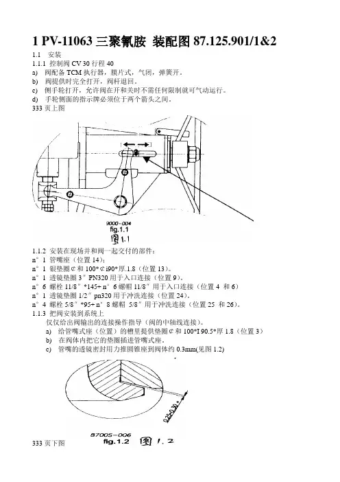
1 PV-11063三聚氰胺装配图87.125.901/1&2 1.1安装1.1.1 控制阀CV 30行程40a) 阀配备TCM执行器,膜片式,气闭,弹簧开。
b) 阀提供时完全打开,阀杆退回。
c) 侧手轮打开,允许阀在开和关时不需任何限制就可气动运行。
d) 手轮侧面的指示牌必须位于两个箭头之间。
333页上图1.1.2 安装在现场并和阀一起交付的部件:n°1 管嘴座(位置14);n°1 银垫圈¢和100*¢i90*厚.1.8(位置13)。
n°1 透镜垫圈3″PN320用于入口连接(位置9)。
n°6 螺栓11/8″*145+ n°6螺帽11/8″用于入口连接(位置4 和6)n°1 透镜垫圈1/2″pn320用于冲洗连接(位置24)。
n°4 螺栓5/8″*95+ n°8螺帽5/8″用于冲洗连接(位置25 和26)。
1.1.3 把阀安装到系统上仅仅给出阀输出的连接操作指导(阀的中轴线连接)。
a) 给管嘴式座(位置)的槽里提供垫圈¢和100*I 90.5*厚1.8(位置3)b) 在阀体内把它的垫圈插进管嘴式座。
c) 管嘴的透镜密封用力推圆锥座到阀体约0.3mm(见图1.2)333页下图d)用铁丝把阀出口和管口紧固,这样阀定位时管口不会退回;e)接阀相关的连接,并定位阀,注意不要小心擦伤阀体和管口之间的垫圈。
f)逐步地小心紧固对角相接的法兰螺帽。
g)阀内外之间的流体密封通过位于管口上的透镜垫圈来保证。
h)镀银垫圈(位置13)防止管口座和阀体之间的缝隙流体进入,这样在维护时拆卸方便。
i)1.1.4a) 把减压过滤器接到气源分配器上。
b) 减压过滤器最大压力必须不要超过8.96bar(130psi).c) 供气压力,也就是说过滤器出口压力,已调整到使阀可工作的压力。
它不能超过4.14bar(60psi).1.1.5 信号输入a) 选择的输入信号是4-20mA。
阀门调试梅索尼兰是一种智能式的定位器,对该种气动阀的调试,首先对控制回路查线和接线方式确认,再次对仪表管道进行吹扫。
注意事项:在进行设置时必须从信号源输入4~20mA电流信号或者从HART(数字通信协议)输入,操作电源来自于4~20mA电流信号或者是12/24VDC电压等多支路供应。
当SVI阀门调节器或控制器没有按钮或者没有显示,如果要进行系统设置或校验,则必须用HART通信协议或者个人计算机上阀门软件来进行阀门参数设定。
该定位器又分为气开式(正作用式:4mA指令对应全关、20mA指令对应全开)、气关式(反作用式:4mA指令对应全开、20mA指令对应全关)和双气缸(厂家说:出厂是什么参数就是什么不需要更改什么参数)三种型号,梅索尼兰有一个简便操作接口、高精度的阀位执行机构、据有自动设置和调整功能。
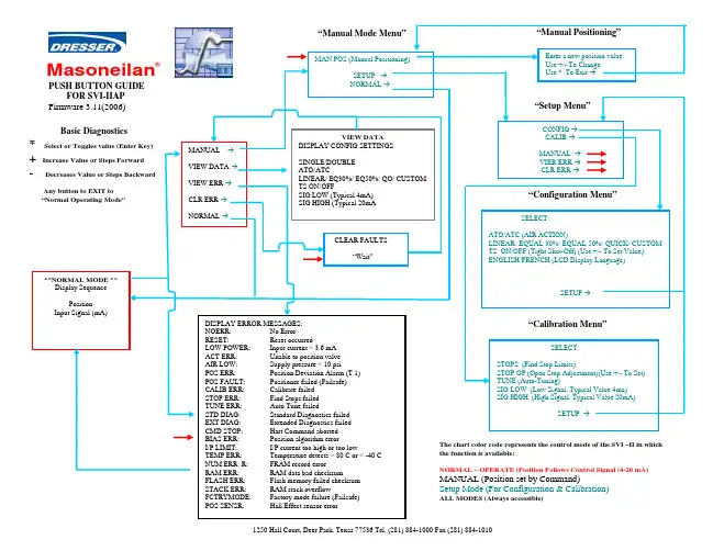
所以我们首先要认识阀门的用户接口(interface),梅索尼兰有三个操作按钮,○1左边一个按钮上标有“*”字样,这个按钮允许我们进行选择或者确认被改的参数;○2中间这个按钮上标有“-”字样,这个按键允许我们从下一个菜单移到上一个菜单,或者对所修改的参数进行减操作;○3右边这个按钮上标有“+”字样,这个按键允许我们从上一个菜单移到下一个菜单,或者对所修改的参数进行加操作。
当我们首次调试时,第一个看到的画面是“POS…”,如果要调整该定位器,首先必须从“POS…”切换到手动位置,画面显示的是:“MAN POS”。
当阀门在自动位置时我们可以用以下方法进行切换。
首先按标记为“+”的键,只到阀门显示(→MAN)字样时,按“*”键就可以进入手动状态,在手动状态时阀门应显示(MAN POS)字样。
这时如果再按下“*”键,就可以进行手动操作该阀门。
如果想切换到自动位置时,只要该定位器显示(MAN POS)字样时,表示阀门现为手动状态。
这时我们只有按下“+”键,只到显示(→OPER)字样,这时按“*”键,阀门将会自动进入自动状态。
调节阀手册第一章概述O.P.小洛维特在现代化工厂的自动控制中,调节阀起着十分重要的作用,这些工厂的生产取决于流动着的液体和气体的正确分配和控制。
这些控制无论是能量的交换、压力的降低或者是简单的容器加料,都需要靠某些最终控制元件去完成。
最终控制元件可以认为是自动控制的“体力”。
在调节器的低能量级和执行流动流体控制所需的高能级功能之间,最终控制元件完成了必要的功率放大作用。
调节阀是最终控制元件的最广泛使用的型式。
其他的最终控制元件包括计量泵、调节挡板和百叶窗式挡板(一种蝶阀的变型)、可变斜度的风扇叶片、电流调节装置以及不同于阀门的电动机定位装置。
尽管调节阀得到广泛的使用,调节系统中的其它单元大概都没有像它那样少的维护工作量。
在许多系统中,调节阀经受的工作条件如温度、压力、腐蚀和污染都要比其它部件更为严重,然而,当它控制工艺流体的流动时,它必须令人满意地运行及最少的维修量。
调节阀在管道中起可变阻力的作用。
它改变工艺流体的紊流度或者在层流情况下提供一个压力降,压力降是由改变阀门阻力或"摩擦"所引起的。
这一压力降低过程通常称为“节流”。
对于气体,它接近于等温绝热状态,偏差取决于气体的非理想程度(焦耳一汤姆逊效应)。
在液体的情况下,压力则为紊流或粘滞摩擦所消耗,这两种情况都把压力转化为热能,导致温度略为升高。
常见的控制回路包括三个主要部分,第一部分是敏感元件,它通常是一个变送器。
它是一个能够用来测量被调工艺参数的装置,这类参数如压力、液位或温度。
变送器的输出被送到调节仪表一一调节器,它确定并测量给定值或期望值与工艺参数的实际值之间的偏差,一个接一个地把校正信号送出给最终控制元件一一调节阀。
阀门改奕了流体的流量,使工艺参数达到了期望值。
在气动调节系统中,调节器输出的气动信号可以直接驱动弹簧-薄膜式执行机构或者活塞式执行机构,使阀门动作、在这种情况下,确定阀位所需的能量是由压缩空气提供的,压缩空气应当在室外的设备中加以干燥,以防止冻结,并应净化和过滤。
SERIES 4X HIGH PERFORMANCEBRA Y/McCANNALOK VAL VESTechnical ManualTHE HIGH PERFORMANCE COMPANYTABLE OF CONTENTSPart Numbering System 1 Seating & Unseating Torques 1 ASME 150 - Torques (Lb-in) 2 ASME 150 - Torques (Lb-in) 3 ASME 300 - Torques (Lb-in) 4 ASME 600 - Torques (Lb-in) 5 ASME 150 - Torques (N-m) 6 ASME 150 - Torques (N-m) 7 ASME 300 - Torques (N-m) 8 ASME 600 - Torques (N-m) 9 Dynamic Torques 10 Dynamic Torque Coefficient11 Subchoked and Choked Flow 12 Subchoked Liquid Flow, Line-size Valve 13 Choked Gas Flow, Reduced-size Valve 13 Maximum Allowable Stem Torques (Lb-in)* 14 Maximum Allowable Stem Torques (N-m)* 15 Valve Sizing Coefficients (Cv) 16 ASME 150 Series 40/41/4A - Valve Sizing Coefficient (Cv) 16 ASME 300 Series 42/43/4B - Valve Sizing Coefficient (Cv) 17 ASME 600 Series 44/45 - Valve Sizing Coefficient (Cv) 17 Valve Sizing Coefficients (Kv) 18 ASME 150 Series 40/41/4A - Valve Sizing Coefficient (Kv) 18 ASME 300 Series 42/43/4B - Valve Sizing Coefficient (Kv) 19 ASME 600 Series 44/45 - Valve Sizing Coefficient (Kv)19 Pressure-Temperature Charts - Standard McCannalok And Firesafe Valves20 Pressure-Temperature Charts - Metal Seated McCannalok Valves 22 Pressure Temperature Charts - Cryogenic McCannalok Valves 23 Examples of Typical Flange to Valve Bolting 24For information on this product and other Bray products please visit us at our web page - 1DOWNSTREAMUPSTREAMSEATING & UNSEATING TORQUESValve orientation to the flow of media affects the torque Torque values are presented in two categories:PART NUMBERING SYSTEMFor available valve sizes per ASMEClass 150, 300 & 600, refer to the DIMENSIONS charts.–EXAMPLE:41-1200-11001-46612 inch (300 mm), Lug Body, ASME Class 150 Mccannalok Valve with 466 Trim.All information herein is proprietary, confidential, and may not be copied or reproduced without the expressed written consent of BRAY INTERNATIONAL, Inc.The technical data herein is for general information only. Product suitability should be based solely upon customer’s detailed knowledge and experience with their application. The right to change or modify product design or product without prior notice is reserved.2All information herein is proprietary, confidential, and may not be copied or reproduced without the expressed written consent of BRAY INTERNATIONAL, Inc.The technical data herein is for general information only. Product suitability should be based solely upon customer’s detailed knowledge and experience with their application. The right to change or modify product design or product without prior notice is reserved. 3All information herein is proprietary, confidential, and may not be copied or reproduced without the expressed written consent of BRAY INTERNATIONAL, Inc.The technical data herein is for general information only. Product suitability should be based solely upon customer’s detailed knowledge and experience with their application. The right to change or modify product design or product without prior notice is reserved.4All information herein is proprietary, confidential, and may not be copied or reproduced without the expressed written consent of BRAY INTERNATIONAL, Inc.The technical data herein is for general information only. Product suitability should be based solely upon customer’s detailed knowledge and experience with their application. The right to change or modify product design or product without prior notice is reserved. 5All information herein is proprietary, confidential, and may not be copied or reproduced without the expressed written consent of BRAY INTERNATIONAL, Inc.The technical data herein is for general information only. Product suitability should be based solely upon customer’s detailed knowledge and experience with their application. The right to change or modify product design or product without prior notice is reserved.6All information herein is proprietary, confidential, and may not be copied or reproduced without the expressed written consent of BRAY INTERNATIONAL, Inc.The technical data herein is for general information only. Product suitability should be based solely upon customer’s detailed knowledge and experience with their application. The right to change or modify product design or product without prior notice is reserved. 7All information herein is proprietary, confidential, and may not be copied or reproduced without the expressed written consent of BRAY INTERNATIONAL, Inc.The technical data herein is for general information only. Product suitability should be based solely upon customer’s detailed knowledge and experience with their application. The right to change or modify product design or product without prior notice is reserved. 9All information herein is proprietary, confidential, and may not be copied or reproduced without the expressed written consent of BRAY INTERNATIONAL, Inc.The technical data herein is for general information only. Product suitability should be based solely upon customer’s detailed knowledge and experience with their application. The right to change or modify product design or product without prior notice is reserved.10DYNAMIC TORQUESWhen a media flows through a butterfly valve, static pressure does not act uniformly on the surfaces of the valve disc Dynamic torque will cause rotary motion when unchecked by the actuator or manual operator possibly resulting in opening or closing of the valve If the dynamic torque is of a magnitude that is greater than the bearing and packing friction torque and there is no actuator in place to maintain disc position, the opening or closing action could result in injury to operating personnel or an interruption of the process Sudden closure (slamming) can cause water hammer damage in lines carrying liquidIn high performance butterfly valves which have the disc offset from the stem and have non-symmetrical disc faces, dynamic torque acts to close the valve if the valve is installed with the seat retainer downstream, but can act to close or open the valve, depending on the position of the disc, if the seat retainer is upstream.Dynamic torque should be calculated as part of the valve actuator sizing procedure or to determine if hand lever operation is acceptable In this regard, the total torque of all service conditions must be consideredThe total torque when the disc is in the seat consists of:1 Seating torque2 Stem packing torque3 Eccentricity torque4 Stem bearing torqueThe total torque when the disc is in the seat is published as seating/unseating torque When the disc is out of the seat, the total torque consists of dynamic torque, stem packing torque, and stem bearing torqueTotal torque changes with the disc position Maximum total torque can occur at shutoff (disc in the seat), at breakaway (motion initiation), or at any open disc position where the product of valve pressure drop and dynamic torque coefficient peaks in combination with prevailing bearing and packing torqueEstimating Dynamic TorqueDynamic torque can be estimated using the following empirical equations:Liquid Flow:Imperial Td (Lb-in) = Ct D³ ❒p Metric Td (N-m) = 0001 Ct D³ ❒p Gas Flow:Imperial Td (Lb-in) = Ct D³ Y ❒p Metric Td (N-m) = 0001 Ct D³ Y ❒pPressure DistributionAll information herein is proprietary, confidential, and may not be copied or reproduced without the expressed written consent of BRAY INTERNATIONAL, Inc.The technical data herein is for general information only. Product suitability should be based solely upon customer’s detailed knowledge and experience with their application. The right to change or modify product design or product without prior notice is reserved.11DYNAMIC TORQUE COEFFICIENTFigure 1 - Seat Retainer DownstreamFigure 2 - Seat Retainer UpstreamAll information herein is proprietary, confidential, and may not be copied or reproduced without the expressed written consent of BRAY INTERNATIONAL, Inc.The technical data herein is for general information only. Product suitability should be based solely upon customer’s detailed knowledge and experience with their application. The right to change or modify product design or product without prior notice is reserved.12SUBCHOKED AND CHOKED FLOWAll information herein is proprietary, confidential, and may not be copied or reproduced without the expressed written consent of BRAY INTERNATIONAL, Inc.The technical data herein is for general information only. Product suitability should be based solely upon customer’s detailed knowledge and experience with their application. The right to change or modify product design or product without prior notice is reserved.13SUBCHOKED LIQUID FLOW, LINE-SIZE VALVE Thus the peak dynamic torque will occur between 30 and 40 degrees open Verify dynamic torque at 35 degrees:Approximate pressure drop = (70+35)/2 = 52 5 psi At 35 degrees: Td = 037 x 24³ x 52 5 = 27,000 Lb-inThe peak dynamic torque of approximately 27,000 Lb-in occurs at about 35 degrees open.When sizing the valve operator, total torque must be considered The total torque when the disc is in the seat consists of seating torque, stem packing torque, eccentricity torque and stem bearing torque The total torque when the disc is in the seat is published as seating/unseating torque (see pages 1-9 When the disc is out of the seat, total torque consists of dynamic torque, stem packing torque, andstem bearing torqueCHOKED GAS FLOW, REDUCED-SIZE VALVE14* Based on stem Material Code 54P (17-4 PH stainless steel, ASTM A564 Type 630 H1150D)MAXIMUM ALLOWABLE STEM TORQUES (Lb-in)*Standard, Fire Safe and Metal Seated Valves15* Based on stem Material Code 54P (17-4 PH stainless steel, ASTM A564 Type 630 H1150D)MAXIMUM ALLOWABLE STEM TORQUES (N-m)*Standard, Fire Safe and Metal Seated ValvesAll information herein is proprietary, confidential, and may not be copied or reproduced without the expressed written consent of BRAY INTERNATIONAL, Inc.The technical data herein is for general information only. Product suitability should be based solely upon customer’s detailed knowledge and experience with their application. The right to change or modify product design or product without prior notice is reserved.16VALVE SIZING COEFFICIENTS (Cv)• Cv stands for Valve Sizing Coefficient• Cv varies with the valve size, angle of opening and the manufacturer’s valve style•Cv is defined as the volume of water in USGPM that will flow through a given restriction or valve opening with apressure drop of one (1) psi at room temperatureAll information herein is proprietary, confidential, and may not be copied or reproduced without the expressed written consent of BRAY INTERNATIONAL, Inc.The technical data herein is for general information only. Product suitability should be based solely upon customer’s detailed knowledge and experience with their application. The right to change or modify product design or product without prior notice is reserved. 17All information herein is proprietary, confidential, and may not be copied or reproduced without the expressed written consent of BRAY INTERNATIONAL, Inc.The technical data herein is for general information only. Product suitability should be based solely upon customer’s detailed knowledge and experience with their application. The right to change or modify product design or product without prior notice is reserved.18VALVE SIZING COEFFICIENTS (Kv)• Kv stands for Valve Sizing Coefficient• Kv varies with the valve size, angle of opening and the manufacturer’s valve style•Kv is defined as the volume of water in Cubic Meters/Hour (m3/hr) that will flow through a given restriction or valve opening with a pressure drop of one (1) bar at room temperatureAll information herein is proprietary, confidential, and may not be copied or reproduced without the expressed written consent of BRAY INTERNATIONAL, Inc.The technical data herein is for general information only. Product suitability should be based solely upon customer’s detailed knowledge and experience with their application. The right to change or modify product design or product without prior notice is reserved. 19All information herein is proprietary, confidential, and may not be copied or reproduced without the expressed written consent of BRAY INTERNATIONAL, Inc.The technical data herein is for general information only. Product suitability should be based solely upon customer’s detailed knowledge and experience with their application. The right to change or modify product design or product without prior notice is reserved.20-2020040060080010001200140016000100200300400500600T e m p e r a t u r e ºFPressure psig-290100200204060801000T e m p e r a t u r e ºCPressure Bar300ASME 300ASME 600ASME 150Stainless Steel Body with RPTFESeatPressure psigAll information herein is proprietary, confidential, and may not be copied or reproduced without the expressed written consent of BRAY INTERNATIONAL, Inc.The technical data herein is for general information only. Product suitability should be based solely upon customer’s detailed knowledge and experience with their application. The right to change or modify product design or product without prior notice is reserved.21-2020040060080010001200140016000100200300400500600T e m p e r a t u r e ºFPressure psig-290100200204060801000T e m p e r a t u r e ºCPressure Bar300ASME 300ASME 600ASME 150Stainless Steel Body with PTFESeatPressure psig22SERIES 4X BRAY/McCANNALOK VALVESTECHNICAL MANUALT e m p e r a t u r e ºFPressure psigT e m p e r a t u r e ºCPressure BarCarbon Steel Body with Inconel ®Seat-2020040060080010001200140016000100200300400500600700800900T e m p e r a t u r e ºFPressure psigT e m p e r a t u r e ºCPressure BarStainless Steel Body with Inconel®Seat-200200400600800100012001400160002004006008001000Cryogenic Valve withFigure 5PRESSURE-TEMPERATURE CHARTS - METAL SEATED MCCANNALOK VALVESAll information herein is proprietary, confidential, and may not be copied or reproduced without the expressed written consent of BRAY INTERNATIONAL, Inc.The technical data herein is for general information only. Product suitability should be based solely upon customer’s detailed knowledge and experience with their application. The right to change or modify product design or product without prior notice is reserved.23SERIES 4X BRAY/McCANNALOK VALVEST e m p e r a t u r e ºFPressure psigT e m p e r a t u r e ºCPressure BarLow Temperature Valve withCarbon Steel Body and Polar ®Seat-60025*******150T e m p e r a t u r e ºFPressure psigT e m p e r a t u r e ºCPressure BarCryogenic Valve withStainless Steel Body and Polar ®Seat-200-3202004006008001000120014001600-100-50-150050100150-100-50-150-1960204060204060801000120ASME 300ASME 150ASME 300ASME 600ASME 150Figure 6PRESSURE TEMPERATURE CHARTS - CRYOGENIC MCCANNALOK VALVESAll information herein is proprietary, confidential, and may not be copied or reproduced without the expressed written consent of BRAY INTERNATIONAL, Inc.The technical data herein is for general information only. Product suitability should be based solely upon customer’s detailed knowledge and experience with their application. The right to change or modify product design or product without prior notice is reserved.24EXAMPLES OF TYPICAL FLANGE TO VALVE BOLTING*25TM-1023_S4X_06_2020All statements, technical information, and recommendations in this bulletin are for generaluse only. Consult Bray representatives or factory for the specific requirements and material selection for your intended application. The right to change or modify product design or product without prior notice is reserved. Patents issued and applied for worldwide.Bray ® is a registered trademark of Bray International, Inc.ENERGY Mining Oil & Gas PowerNuclear Power INDUSTRIAL Chemical Pulp & Paper Textile MarineWATERWater / Wastewater Ultra Pure Water Desalination IrrigationINFRASTRUCTURE Beverage & Food TransportationHeating, Ventilation & Air Conditioning (HVAC)BRAY FLOW CONTROL SOLUTIONS ARE AVAILABLE FOR A VARIETY OF INDUSTRIES.THE SMART CHOICE FOR FLOW CONTROL SINCE 1986. WITH MORE THAN 300 LOCATIONS WORLDWIDE, FIND A REPRESENTATIVE NEAR YOU AT US HEADQUARTERS Bray International, Inc.13333 Westland East Blvd.Houston, Texas 77041Tel: +1.281.894.5454EUROPE HEADQUARTERSBray Armaturen & Antriebe Europa Halskestraße 25D-47877 Willich GermanyTel: +49.173.1621.471CHINA HEADQUARTERSBray Controls (ZheJiang) Co. Limited 98 GaoXin #6 RoadXiaoShan Economic & Development Zone HangZhou, ZheJiang 311231, P .R. China Tel: +86.571.8285.2200INDIA HEADQUARTERSBray Controls India Pvt. Ltd.Plot No. H-18 & H-19, SIPCOT Industrial ParkVallam Vadagal, Echoor Post, Sriperumbudur Taluk Kancheepuram District, Tamil Nadu - 631 604Tel: +91.44.67170100© 2020 BRAY INTERNATIONAL, INC. All rights reserved.。
阀门调试梅索尼兰是一种智能式的定位器,对该种气动阀的调试,首先对控制回路查线和接线方式确认,再次对仪表管道进行吹扫。
注意事项:在进行设置时必须从信号源输入4~20mA电流信号或者从HART(数字通信协议)输入,操作电源来自于4~20mA电流信号或者是12/24VDC电压等多支路供应。
当SVI阀门调节器或控制器没有按钮或者没有显示,如果要进行系统设置或校验,则必须用HART通信协议或者个人计算机上阀门软件来进行阀门参数设定。
该定位器又分为气开式(正作用式:4mA指令对应全关、20mA指令对应全开)、气关式(反作用式:4mA指令对应全开、20mA指令对应全关)和双气缸(厂家说:出厂是什么参数就是什么不需要更改什么参数)三种型号,梅索尼兰有一个简便操作接口、高精度的阀位执行机构、据有自动设置和调整功能。
所以我们首先要认识阀门的用户接口(interface),梅索尼兰有三个操作按钮,○1左边一个按钮上标有“*”字样,这个按钮允许我们进行选择或者确认被改的参数;○2中间这个按钮上标有“-”字样,这个按键允许我们从下一个菜单移到上一个菜单,或者对所修改的参数进行减操作;○3右边这个按钮上标有“+”字样,这个按键允许我们从上一个菜单移到下一个菜单,或者对所修改的参数进行加操作。
当我们首次调试时,第一个看到的画面是“POS…”,如果要调整该定位器,首先必须从“POS…”切换到手动位置,画面显示的是:“MAN POS”。
当阀门在自动位置时我们可以用以下方法进行切换。
首先按标记为“+”的键,只到阀门显示(→MAN)字样时,按“*”键就可以进入手动状态,在手动状态时阀门应显示(MAN POS)字样。
这时如果再按下“*”键,就可以进行手动操作该阀门。
如果想切换到自动位置时,只要该定位器显示(MAN POS)字样时,表示阀门现为手动状态。
这时我们只有按下“+”键,只到显示(→OPER)字样,这时按“*”键,阀门将会自动进入自动状态。
梅索尼兰SVI II AP 智能定位器操作说明书美国德莱赛公司1 of 43授权德莱赛公司对出售的产品在货物发运一年内承担由于产品本身材料或加工工艺上的缺陷原因造成不能使用的,进行免费更换。
德莱赛公司保留在没有向外宣布的情况下,停止生产或改变产品的材料和设计规格的权利。
本说明书是定位器SVI II AP 和其配套软件ValVue的说明材料。
定位器SVI II AP 仅能使用德莱赛公司认可的配套软件,软件的购买和注册请与德莱赛公司联系。
关于本手册本手册适用于以下设备和软件:定位器SVI II AP-2 到SVI II AP-3 ValVue 2.4 或更高版本AMS ValVue SNAP –ON 2.4 版本或更高使用为SVI II AP 所发布DD 的HH375 HART 手持机Masoneilan 仪表型号2020xCA 本手册中的内容在没有事先告知的情况下有可能改变。
本手册的全部或部分内容在没有得到德莱赛公司的认可后不得进行复制或引用。
不保证用户在本手册中未提到的特殊情况下使用SVI II AP 和其配套软件的适用性。
请将你在本手册中发现的错误内容告知供应商或通过 网站告知我们。
版权本手册中所有的软件的版权都属于德莱赛公司。
产品的设计制造技术知识产权也属于德莱赛公司所有。
Masoneilan,FVP,SVI,ValVue 都由德莱赛公司进行了商标注册,在这里所有信息在发布之时都保证正确无误,有可能在不事先通知的情况下进行改动。
2006 年德莱赛公司版权所有,保留所有权限。
安全事项本部分包括的安全事项是在SVI AP 的手册中出现的安全标志和对其的定义。
非常重要—在安装SVI II AP 定位器前请务必认真阅读本使用手册。
安全标示—本手册在需要的地方会出现包括危险DANGER、警告WARNING、注意CAUTION 和说明NOTE 等标示,帮助你注意有关安全事项。
在安装和维修设备前请仔细阅读本手册的相关信息内容。
球阀使用说明书汇编:校对:审核:日期:雷蒙德(北京)阀门制造有限公司球阀使用说明书球阀是一种截断阀,它的启闭件(球体)有一个圆形的通道,围绕着阀体的垂直中心线作回转90o的运动,接通或截断管路中的介质,故称作球阀。
本操作说明书适用Q41F(Y)、Q341F(Y)、Q47F(Y)、Q347F(Y),全径、缩径,压力PN16~PN250(Class150Lb~1500Lb)固定球、浮动球球阀。
1、技术参数1.1 阀门的公称压力和公称通径(见下表:) bar/LbDN Mm/"PN16/20Class150LbPN25/40/50Class300LbPN64Class400LbPN100Class600LbPN150/160Class900LbPN250Class1500Lb15/0.5" √√√√√√20/0.75" √√√√√√25/1" √√√√√√40/1.5" √√√√√√50/2" √√√√√√65/2.5" √√√√√√80/3" √√√√√√100/4" √√√√√√125/5" √√√√√√150/6" √√√√√√200/8" √√√√√√250/10" √√√√√√300/12" √√√√√√350/14" √√√√√√400/16" √√√√√√450/18" √√√√√√500/20" √√√√√√600/24" √√√√√√700/28" √√√√√NA 800/32" √√√√√NA 900/36" √√√√√NA 注:NA 不适用1.2 阀门的材料、温度和介质适用温度适用介质CF8/304 -196℃~200℃液氧等LC3/LF3 -101℃~200℃乙烯等LCB/LF2 -46℃~200℃二氧化碳WCB/A105 -29℃~425℃油、气、水CF8/304 -29℃~200℃硝酸类CF8M/316 -29℃~200℃醋酸类WC6/F11 -29℃~570℃氢气、高温蒸汽WC9/F22 -29℃~570℃氢气、高温蒸汽2、技术规范2.1 产品标准GB/T 12237、GB/T21385、API 6D2.2 法兰连接结构长度按:GB/T12221、JB1686、API 6D;2.3 对焊连接结构长度按:GB/T12221、API 6D;2.4 端法兰连接尺寸按:GB/T9113、JB/T79、HG/T20592、ASME B16.5;2.5 阀门的火灾安全设计按:GB/T 12237、GB/T21385、API 607;2.6 阀门的防静电设计按:GB/T 12237、API 6D;2.7 阀门的最小通径按:GB/T 12237、API 6D;2.8 焊接端连接尺寸按:GB/T12224、ASME B16.25;2.9 检查和试验按:GB/T13927、JB/T9092、API 6D。
MASONEILAN21000系列控制阀操作手册(中文版)二○○三年目录调节阀代码注释 (2)1 引言 (3)2 概述 (3)3 拆除 (3)4 安装 (3)5 送气管道 (4)6 阀体拆卸 (4)6.1 螺纹阀芯 (4)6.2 速换阀芯 (5)7 维修/检修 (6)7.1 螺纹基座拆除 (6)7.2 套管拆除 (6)7.3 研磨基座 (6)7.3A 螺纹阀芯…………………………………………………7.3B 速换阀芯…………………………………………………7.4 逻辑双重端阀……………………………………………………7.5 阀芯轴插杆………………………………………………………7.6 包装箱(标准) ……………………………………………………7.7 包装箱(润滑) ……………………………………………………7.8 软基座活塞………………………………………………………8 阀体再组装……………………………………………………………8.1 螺纹微调…………………………………………………………8.2 速换微调…………………………………………………………9 附图……………………………………………………………………模型序号图1尺寸和比率图21 引言在安装、运行和维修该设备之前,应全面审查并理解下列指南。
在整篇文章中,都有安全和警告注意事项,必须严格坚持,否则,会造成严重损坏或者设备失灵。
Masoneilan在非常熟练的服务工程师,他们广泛应用于阀门和部件的运行、维修和检修。
另外,还进行常规的培训计划以培训我们的阀门及仪表的操作、维修和应用的客户服务与仪表人员。
通过你们的Masoneilan代表或者地区办公室,进行这些服务的安排。
在进行维修时,只用Masoneilan的更换部件。
可以通过当地的Masoneilan代表或者地区办公室购买部件。
订购部件时,通常包括检修机组的模型和系列号。
2 概述安装和维修指南应用于Masoneilan 21000系列控制阀的所有尺寸和比率,不管使用的微调类型。
High Flow Valve Actuation RangeD1Description of ApplicationsControl of single or double acting pneumatic actuators, in safe or dangerous areas.NAMUR Interfaces 1/4" & 1/2"The interface design is conform to the NAMURstandard and to the VDI/VDE 3845 recommendations of the actuator industry. It allows a compact design of the actuator/valve unit. In case of a 3/2 function,the air of the actuator spring chamber also flowsthrough the pilot valve (re-breather function).This prevents corrosion of the actuator springs.Market DescriptionProcess industriesChemical, Petrochemical industries Oil & GasWater & Sewage Pulp & Paper Food & BeveragePharmaceutical industryPowder Dosing-Transportation Air Dryers● High flow: 1.250 l/min (1/4"), 3.000 l/min (1/2")● Compact design ● Long life expectancy● Coil Modularity: a large part of the range is compatiblewith different types of coils, ATEX, non ATEX and Low Power● Fail safe standard● Reduced inventory (3/2 & 5/2 functions with the samevalve on 341Nx5 series)● Mechanical part of the valve ATEX certifiedaccording standard EN 13463-1 & -5 (with maximum capability of zone 1-21 )5/2 and 5/3 valves.Customer Value PropositionGeneralNAMUR Valves G1/4" Series Solenoid Operated VersionsN03-N05 SeriesDimensions Reference 3Dimensions Reference 4404040403232322222222232326767676767505050505013 13 13 13 13 13 13 13 44 44 44 222236.536.5G1/4" (2x)G1/4" (3x)G1/4" (3x)G1/4" (3x)M5M5M5M52323232336,52424242423232323868610290 121414101212344355513332227.27.27.27.2Dimensions Reference 1Dimensions Reference 2NAMUR Valves G1/4" Series Solenoid Operated VersionsN33-N35 Series4032100232324 4032130232324 14 12 2432DIN 43650AG1/8"5322973813 19.51322 2432DIN 43650AG1/8"22 53G1/4" (3x)M522327.5Dimensions Reference 5Dimensions Reference 640404032323213 13 13 13 13 13 44 22 22 22 22 86868623232323232324 24 24 355133G1/4" (2x)G1/4" (3x)G1/4" (3x)G1/8G1/8G1/8M5M5M52222227.27.27.2External Pressure Air Operated Series 5xx N03 SeriesDimensions Reference 7Dimensions Reference 8Dimensions Reference 9Solenoid Operated Versions N04 VersionsDimensions Reference 10Dimensions Reference 11Dimensions Reference 12Solenoid Operated VersionsN34 Series ArrayDimensions Reference 13Dimensions Reference 14Dimensions Reference 15NAMUR Valves G1/2" SeriesExternal Pressure Air Operated Series 5 xx N04 SeriesDimensions Reference 16Dimensions Reference 17Port sizeOrificeQ NAdmissible differential pressure (bar)maximum Fluid TemperatureSeat discReference numberConsumption Power (Watt)Weight (g)Elect.Group Dim.Ref.G mm l/minminDC=AC~Min °C Max °C Valve without man. overrideHousing Coil DC=AC~3/2 External pressure air operatedCombined spring & air return (monostable)External pressure supply 2.5 to 10 bar1/2123000 2.51010-2050NBR 531N04-w/o --620-165/2 External pressure air operatedCombined spring & air return (monostable)External pressure supply 2.5 to 10 bar1/21230002.51010-2050NBR541N04-w/o--600-1713213524Dimensions Reference 18Dimensions Reference 19Solenoid Operated Versions P03 VersionsSolenoid Operated Versions P33 VersionsDimensions Reference 20Dimensions Reference 21Solenoid Operated Versions P04 VersionsDimensions Reference 22Dimensions Reference 23Solenoid Operated Versions P34 VersionsDimensions Reference 24Dimensions Reference 25Banjo Valves - G1/4” & G1/8” Series Solenoid Operated VersionsB14-B04 Versions ArrayDimensions Reference 26Dimensions Reference 27"The housing kit is already included in the valve reference, it is not needed to order it separately."To Order a Coil choose Coil Ref + Voltage Code, example:496131 for 24 VDC =496131C2Dimensions Reference 1Dimensions Reference 2This coil can be mounted with every Parker solenoid valvescorresponding to the specified Coil Group. See column "CoilGroup" within valve pages. This coil is designed for valvesDIN plug connector to be ordered separately (see coil accessoriesSafeAreaDouble frequency(Dim. Ref. 1)COMPACT COILS FOR N03 - N04 - N05 SeriesDIN PLUG CONNECTION1.2C O I L G R O U PThis coil can be mounted with every Parker ATEX solenoid valvesControl of solenoid valves in dangerous areas where explosion-proof The synthetic material encapsulation of the coil provides an effective A T E X Z o Double FrequencyTo Order a Coil choose Coil Ref + Voltage Code , example: 496637 for 24 VDC = 496637C2See column "Coil Group" within valve pages. This is an S a f e A r e aDouble frequencyThese coils must be used with suitable housings, see example below:The coil assembly kit Ref. 2995 corresponds to the "housing" of Lucifer ® valve numbering system (Valve - housing - coil - voltage). It is composed of a nameplate, a label giving details of the valve type, a round washer and a nut to ensure the fixing between 32 mm coil and the valve.COILS FOR N33-N34-N35 Series DIN PLUG CONNECTION2.0/2.1C O I L G R O U PTo Order a Coil choose Coil Ref + Voltage Code , example: 481865 for 24 VDC = 481865C2S a fe A r e aThese coils must be used with suitable housings, see examples below:2.0/2.1C O I L G R O U PCOILS FOR N33-N34-N35 Series SCREW TERMINALTo Order a Coil choose Coil Ref + Voltage Code , example: 4828 for 24 VDC = 481000C2Ref. 4270 - Protection IP 44 according to IEC / EN 60529 standard (with cable gland) Ref. 4538 - Protection IP 67 according to IEC / EN 60529 standardCoils and Spare Parts InformationsSafeAreaCOILS FOR N339x-N349x-N359x SeriesLOW POWER - DIN PLUG CONNECTION6.0C O I L G R O U PTo Order a Coil choose Coil Ref + Voltage Code, example:482740 for 24 VDC = 482740C2These coils must be used withsuitable housings, see examplebelow:The coil assembly kit Ref. 2995corresponds to the "housing" of Lucifer®valve numbering system (Valve - housing- coil - voltage). It is composed of anameplate, a label giving details of thevalve type, a round washer and a nut toensure the fixing between 32 mm coiland the valve.LCIE 05 ATEX 6003 XTo Order a Coil choose Coil Ref + Voltage Code, example:495870 for 24 VDC = 495870C2These coils can be mounted with every Parker ATEX solenoidvalves corresponding to the specified Coil Group. See columnControl of solenoid valves in dangerous areas where non sparking protection Ex nc AC IIC T3 to T4 is required.Ease of mounting in confined space - offers shock and corrosionprotection - simplifies conversion of existing equipment to otherrequirements, etc. Coils conforms to the IEC/CENELEC safetyThese coils must be used withsuitable housings, see examplebelow:The coil assembly kit Ref. 2995corresponds to the "housing" of Lucifer®valve numbering system (Valve - housing- coil - voltage).It is composed of a nameplate, a labelgiving details of the valve type, a roundwasher and a nut to ensure the fixingbetween 32 mm coil and the valve.ATEXZThese coils must be used withsuitable housings, see examplebelow:The coil assembly kit Ref. 2995corresponds to the "housing" of Lucifer®valve numbering system (Valve - housing- coil - voltage).It is composed of a nameplate, a labelgiving details of the valve type, a roundwasher and a nut to ensure the fixingbetween 32 mm coil and the valve.ATEXZone2-22 To Order a Coil choose Coil Ref + Voltage Code, example:496125 for 24 VDC = 496125C2495905*495905.05A T E X z o n e 1-21To Order a Coil choose Coil Ref + Voltage Code , example: 495905 for 24 VDC = 495905C2ATEXzone1-21To Order a Coil:Coil Ref + Voltage Code, example:495900 for 24 VDC = 495900C2A T E X z o n e 1-21To Order a Coil choose Coil Ref + Voltage Code , example: 483371 for 24 VDC = 483371C2Fuses:Both electrical parts have to be connected in series with a safety fuse according to IEC 60127-3.483371:DC: 24 V, 400 mA - 48V, 250 mA - 110 V, 100 mAAC 50HZ: 24 V, 630 mA - 48V, 315 mA - 110 V, 160 mA - 220/230 V, 80 mA 494040:DC: 12 V, 400 mA - 24V, 200 mA - 48 V, 100 mA - 110V, 50 mA AC 50HZ: 24 V, 250 mA - 48V, 125 mA - 110/115 V, 63 mA -220/230 V, 32 mATo Order a Coil choose Coil Ref + Voltage Code , example: 495910 for 28 VDC = 495910N7A T E X z o n e 1-21COILS FOR N339x-N349x-N359x SeriesTo Order a Coil choose Coil Ref + Voltage Code , example: 483580.01 for 28 VDC = 483580.01N7A T E X z o narmature, three diodes circuit and DIN plug connection. The ImportantThe intrinsically safe supply circuit should have enough capacity in all environmental conditions to assure a minimum operating current of 35 mA through the coil.The minimal holding current is 20 mA.For the barrier compatibility see the corresponding table in appendix section.These coils must be used with suitable housings, see example below:The coil assembly kit Ref. 2995 corresponds to the "housing" of Lucifer ® valve numbering system (Valve - housing - coil - voltage).It is composed of a nameplate, a label giving details of the valve type, a round washer and a nut to ensure the fixing between 32 mm coil and the valve.Spare Parts Mounting Kit and AccessoriesKit for G1/4" Modelswithout conversion plate (N x 3 Series)Kit includes the 2 mounting screws M5 x 25 A2, the dowel pin M5 x 10 A2, the 2 O-rings NBR 15 x 2.5Order code: 496132Exhaust Flow RegulatorsMaterial Body: Brass Filter element: Sintered bronzeSpring: Stainless SteelSeal: NBRG1/8" Order code: 496551 G1/4" Order code: 496552 G1/2" Order code: 496553Kit for G1/2" Models (N x 4 Series)Kit includes the 2 mounting screws M6 x 35 A2, the dowel pin M6 x 12 A2, the 2 O-rings NBR 24 x 3Order code: 496133Kit for G1/4" Modelswith conversion plate (N x 5 Series)Kit includes the 2 mounting screws M5 x 35 A2, the dowel pin M5 x 20 A2,the conversion plate equipped with its seals Order code: 496742 (equipped plate)Order code: 496852 (screws + pin)Connector DIN AConnector DIN43650 AA Pg9 2P+E Order code: 486586Housing for 22 mm CoilPlastic nut with O-ring Order code: 3125Connector DIN43650 AB Pg9 2P+E Order code: 481043AerospaceKey MarketsAftermarket servicesCommercial transportsEnginesGeneral & business aviationHelicoptersLaunch vehiclesMilitary aircraftMissilesPower generationRegional transportsUnmanned aerial vehiclesKey ProductsControl systems &actuation productsEngine systems& componentsFluid conveyance systems& componentsFluid metering, delivery& atomization devicesFuel systems & componentsFuel tank inerting systemsHydraulic systems& componentsThermal managementWheels & brakesElectromechanicalKey MarketsAerospaceFactory automationLife science & medicalMachine toolsPackaging machineryPaper machineryPlastics machinery & convertingPrimary metalsSemiconductor & electronicsTextileWire & cableKey ProductsAC/DC drives & systemsElectric actuators, gantry robots& slidesElectrohydrostatic actuation systemsElectromechanical actuation systemsHuman machine interfaceLinear motorsStepper motors, servo motors,drives & controlsStructural extrusionsPneumaticsKey MarketsAerospaceConveyor & material handlingFactory automationLife science & medicalMachine toolsPackaging machineryTransportation & automotiveKey ProductsAir preparationBrass fittings & valvesManifoldsPneumatic accessoriesPneumatic actuators & grippersPneumatic valves & controlsQuick disconnectsRotary actuatorsRubber & thermoplastic hose& couplingsStructural extrusionsThermoplastic tubing & fittingsVacuum generators, cups & sensorsFluid & Gas HandlingKey MarketsAerial liftAgricultureBulk chemical handlingConstruction machineryFood & beverageFuel & gas deliveryIndustrial machineryLife sciencesMarineMiningMobileOil & gasRenewable energyTransportationKey ProductsCheck valvesConnectors for low pressurefluid conveyanceDeep sea umbilicalsDiagnostic equipmentHose couplingsIndustrial hoseMooring systems &power cablesPTFE hose & tubingQuick couplingsRubber & thermoplastic hoseTube fittings & adaptersTubing & plastic fittingsHydraulicsKey MarketsAerial liftAgricultureAlternative energyConstruction machineryForestryIndustrial machineryMachine toolsMarineMaterial handlingMiningOil & gasPower generationRefuse vehiclesRenewable energyTruck hydraulicsTurf equipmentKey ProductsAccumulatorsCartridge valvesElectrohydraulic actuatorsHuman machine interfacesHybrid drivesHydraulic cylindersHydraulic motors & pumpsHydraulic systemsHydraulic valves & controlsHydrostatic steeringIntegrated hydraulic circuitsPower take-offsPower unitsRotary actuatorsSensorsProcess ControlKey MarketsAlternative fuelsBiopharmaceuticalsChemical & refiningFood & beverageMarine & shipbuildingMedical & dentalMicroelectronicsNuclear PowerOffshore oil explorationOil & gasPharmaceuticalsPower generationPulp & paperSteelWater/wastewaterKey ProductsAnalytical InstrumentsAnalytical sample conditioningproducts & systemsChemical injection fittings& valvesFluoropolymer chemicaldelivery fittings, valves& pumpsHigh purity gas deliveryfittings, valves, regulators& digital flow controllersIndustrial mass flow meters/controllersPermanent no-weld tube fittingsPrecision industrial regulators& flow controllersProcess control doubleblock & bleedsProcess control fittings, valves,regulators & manifold valvesSealing & ShieldingKey MarketsAerospaceChemical processingConsumerFluid powerGeneral industrialInformation technologyLife sciencesMicroelectronicsMilitaryOil & gasPower generationRenewable energyTelecommunicationsTransportationKey ProductsDynamic sealsElastomeric o-ringsElectro-medical instrumentdesign & assemblyEMI shieldingExtruded & precision-cut,fabricated elastomeric sealsHigh temperature metal sealsHomogeneous & insertedelastomeric shapesMedical device fabrication& assemblyMetal & plastic retainedcomposite sealsShielded optical windowsSilicone tubing & extrusionsThermal managementVibration dampeningParker’s Motion & Control TechnologiesAt Parker, we’re guided bya relentless drive to helpour customers become moreproductive and achievehigher levels of profitabil-ity by engineering the bestsystems for their require-ments. It means looking atcustomer applications frommany angles to find newways to create value. What-ever the motion and controltechnology need, Parker hasthe experience, breadth ofproduct and global reachto consistently deliver. Nocompany knows more aboutmotion and control technol-ogy than Parker. For furtherinfo call 00800 27 27 5374Climate ControlKey MarketsAgricultureAir conditioningConstruction MachineryFood & beverageIndustrial machineryLife sciencesOil & gasPrecision coolingProcessRefrigerationTransportationKey ProductsAccumulatorsAdvanced actuatorsCO2controlsElectronic controllersFilter driersHand shut-off valvesHeat exchangersHose & fittingsPressure regulating valvesRefrigerant distributorsSafety relief valvesSmart pumpsSolenoid valvesThermostatic expansion valvesFiltrationKey MarketsAerospaceFood & beverageIndustrial plant & equipmentLife sciencesMarineMobile equipmentOil & gasPower generation &renewable energyProcessTransportationWater PurificationKey ProductsAnalytical gas generatorsCompressed air filters & dryersEngine air, coolant, fuel & oil filtration systemsFluid condition monitoring systemsHydraulic & lubrication filtersHydrogen, nitrogen & zeroair generatorsInstrumentation filtersMembrane & fiber filtersMicrofiltrationSterile air filtrationWater desalination & purification filters & systemEurope, Middle East, AfricaAE - United Arab Emirates, Dubai Tel: +971 4 8127100 ********************AT - Austria, Wiener Neustadt Tel: +43 (0)2622 23501-0 *************************AT - Eastern Europe, Wiener NeustadtTel: +43 (0)2622 23501 900 ****************************AZ - Azerbaijan, Baku Tel: +994 50 2233 458****************************BE/LU - Belgium, Nivelles Tel: +32 (0)67 280 900*************************BG - Bulgaria, Sofia Tel: +359 2 980 1344**************************BY - Belarus, Minsk Tel: +375 17 209 9399*************************CH - Switzerland, Etoy Tel: +41 (0)21 821 87 00*****************************CZ - Czech Republic, Klecany Tel: +420 284 083 111*******************************DE - Germany, Kaarst Tel: +49 (0)2131 4016 0*************************DK - Denmark, Ballerup Tel: +45 43 56 04 00*************************ES - Spain, Madrid Tel: +34 902 330 001 ***********************FI - Finland, Vantaa Tel: +358 (0)20 753 2500 *************************FR - France, Contamine s/Arve Tel: +33 (0)4 50 25 80 25 ************************GR - Greece, Athens Tel: +30 210 933 6450 ************************HU - Hungary, Budaörs Tel: +36 23 885 470*************************IE - Ireland, Dublin Tel: +353 (0)1 466 6370 *************************IT - Italy, Corsico (MI) Tel: +39 02 45 19 21 ***********************KZ - Kazakhstan, Almaty Tel: +7 7273 561 000****************************NL - The Netherlands, Oldenzaal Tel: +31 (0)541 585 000 ********************NO - Norway, Asker Tel: +47 66 75 34 00************************PL - Poland, Warsaw Tel: +48 (0)22 573 24 00 ************************PT - Portugal, Leca da Palmeira Tel: +351 22 999 7360**************************RO - Romania, Bucharest Tel: +40 21 252 1382*************************RU - Russia, Moscow Tel: +7 495 645-2156************************SE - Sweden, Spånga Tel: +46 (0)8 59 79 50 00 ************************SK - Slovakia, Banská Bystrica Tel: +421 484 162 252**************************SL - Slovenia, Novo Mesto Tel: +386 7 337 6650**************************TR - Turkey, Istanbul Tel: +90 216 4997081 ************************UA - Ukraine, Kiev Tel +380 44 494 2731*************************UK - United Kingdom, Warwick Tel: +44 (0)1926 317 878 ********************ZA - South Africa, Kempton Park Tel: +27 (0)11 961 0700*****************************North AmericaCA - Canada, Milton, Ontario Tel: +1 905 693 3000US - USA, Cleveland Tel: +1 216 896 3000Asia PacificAU - Australia, Castle Hill Tel: +61 (0)2-9634 7777CN - China, Shanghai Tel: +86 21 2899 5000HK - Hong Kong Tel: +852 2428 8008IN - India, MumbaiTel: +91 22 6513 7081-85JP - Japan, Tokyo Tel: +81 (0)3 6408 3901KR - South Korea, Seoul Tel: +82 2 559 0400MY - Malaysia, Shah Alam Tel: +60 3 7849 0800NZ - New Zealand, Mt Wellington Tel: +64 9 574 1744SG - Singapore Tel: +65 6887 6300TH - Thailand, Bangkok Tel: +662 186 7000-99TW - Taiwan, Taipei Tel: +886 2 2298 8987South AmericaAR - Argentina, Buenos Aires Tel: +54 3327 44 4129BR - Brazil, Sao Jose dos Campos Tel: +55 800 727 5374 CL - Chile, Santiago Tel: +56 2 623 1216MX - Mexico, Apodaca Tel: +52 81 8156 6000Parker WorldwideE d . 03 M a r c h 2014EMEA Product Information Centre Free phone: 00 800 27 27 5374(from AT , BE, CH, CZ, DE, DK, EE, ES, FI, FR, IE, IL,IS, IT , LU, MT , NL, NO, PL, PT , RU, SE, SK, UK, ZA)US Product Information Centre Toll-free number: 1-800-27 27 537Catalogue 1101/UK - 06/2015© 2014 Parker Hannifin Corporation.All rights reserved.。
Products Solutions Services操作手册Liquiphant FTL41音叉液位开关音叉液位开关BA01893F/28/ZH/02.19714412012019-06-29Liquiphant FTL412Endress+HauserLiquiphant FTL41目录Endress+Hauser3目录1文档信息 (5)1.1图标 ................................51.1.1安全图标......................51.1.2电气图标......................51.1.3特定信息图标...................51.1.4图中的图标.....................52基本安全指南 (6)2.1人员要求.............................62.2指定用途.............................62.2.1使用错误......................62.3工作场所安全.........................62.4操作安全.............................62.5产品安全.............................73产品描述 (7)3.1产品设计 (7)4到货验收和产品标识 (7)4.1到货验收.............................74.2产品标识.............................84.2.1铭牌 ..........................84.2.2制造商地址.....................84.3储存和运输...........................84.3.1储存条件......................84.3.2运输设备......................85安装 (9)5.1安装条件.............................95.1.1注意开关点.....................95.1.2注意介质粘度的影响.............105.1.3避免黏附.....................115.1.4预留安装间隙..................115.1.5支撑设备.....................125.1.6焊座,带泄露检测孔 ............125.2安装测量设备........................125.2.1所需工具.....................125.2.2安装.........................135.3滑动套管 ...........................145.4安装后检查 (14)6电气连接 (14)6.1连接条件 ...........................146.1.1连接保护性接地端(PE) ........146.2连接测量设备........................156.2.1电子插件FEL42:三线制连接,直流DC-PNP 型..................156.2.2电子插件FEL44:通用电流连接型,带继电器输出..............166.2.3电子插件FEL48:两线制连接,NAMUR 信号(> 2.2 mA/< 1.0 mA)....................196.2.4电缆入口 .....................206.3连接后检查 (21)7操作方式 (21)7.1操作方式概述 ........................217.1.1操作方法 .....................217.1.2电子插件上的部件.. (21)8调试 (21)8.1功能检查............................218.2测量设备上电 (22)9诊断和故障排除 (22)9.1电子插件上的LED 指示灯 (22)10维护 (22)10.1维护任务 (22)10.1.1清洁 (22)11维修 (23)11.1概述...............................2311.1.1维修理念.....................2311.1.2防爆型设备的维修..............2311.2备件...............................2311.3返厂...............................2311.4废弃...............................2312附件 (24)12.1设备专用附件 ........................2412.1.1保护盖,适用金属单腔室外壳......2412.1.2插头.........................2412.2常压滑动套管........................2512.3高压滑动套管........................2613技术参数 (27)13.1输入...............................2713.1.1测量变量 .....................2713.1.2测量范围 .....................2713.2输出...............................2713.2.1输出与输入....................2713.2.2输出信号 .....................2713.2.3防爆连接参数 .................2813.3环境条件............................2913.3.1环境温度范围 .................2913.3.2储存温度 .....................2913.3.3湿度 ........................2913.3.4海拔高度.....................2913.3.5气候等级 .....................2913.3.6防护等级.....................3013.3.7抗振性 .......................3013.3.8抗冲击性.....................30目录Liquiphant FTL4113.3.9机械负载 (30)13.3.10电磁兼容性(EMC) (30)13.4过程条件 (30)13.4.1过程温度范围 (30)13.4.2热冲击 (31)13.4.3过程压力范围 (31)13.4.4测试压力 (31)13.4.5密度 (32)13.4.6密闭压力 (32)13.5其他技术参数 (32)4Endress+HauserLiquiphant FTL41文档信息Endress+Hauser 51文档信息1.1图标1.1.1安全图标危险状况警示图标。
梅索尼兰MASONIELANSV-II 阀门定位器调校步骤第一种方法:1.在**DEVICESETUP** 〔设备设置〕菜单模式选择第3项**SETUPWIZARD** 〔设备向导〕选项菜单并进入**AIRACTIONCONFIGURARTION** 菜单。
2.在AIRACTIONCONFIGURARTION 菜单项选择择第1项SKIPTHISTASK 〔跳过〕进入FINDVALVESTOPS 菜单。
3.在FINDVALVESTOPS菜单下选择第2项RUNAUTOSTOPS作为定位器的全开全关校验,完成后进入AUTOTUNE 菜单。
4.在AUTOTUNE 菜单下选择第2项RUNAUTOTUNE 做定位器PID参数校验,完成后进入RESETTOFACTORYDEFAULT 菜单。
5.在RESETTOFACTORYDEFAULT 菜单下选择第1项SKIPTHISTASK〔跳过〕返回初始菜单。
注意:SVIIIAP定位器用HART375校验时,HART375必须经过升级后才能使用。
第二种方法:1.将定位器安装到阀门,接上正常的电气信号,连接HART375与定位器,进入NORMALMODE菜单模式。
2.在NORMALMODE 菜单下选择第4项MANUALMODEMENU 〔手动模式菜单〕并进入。
3.在MANUALMODEMENU 〔手动模式菜单〕下选择第3项CALIBRATEMENU 〔校验菜单〕,并进入。
4.在CALIBRATEMENU 〔校验菜单〕下选择第1项RANGE并进入CHOOSE菜单。
5.在CHOOSE菜单下选择AUTOSTOPS作定位器快开快关校验。
6.完成后返回CALIBRATE MENU〔校验菜单〕,选择第2项TUNING 并进入TUNING CHOOSE选项菜单。
7.在TUNINGCHOOSE 选项菜单下选择第2项AUTOTUNE 自动校验PID。
8.完成后按以上步骤返回到最初菜单。
1梅索尼兰MASONIELANSV-II阀门定位器调校步骤通讯器与电气定位器连接后,开机显示:HARTAPPLICATION(HART协议应用)FOUNADTIONFIELDBUSAPPLICATION(现场总线协议应用)SETTINGS(375内部设置)LISTENFORPC(浏览PC机)SCRATCHPAD〔翻开文本编辑器〕选择第一项HARTAPPLICATION后按Delete键后显示:1、OFFLINE(离线设置)2、ONLINE(在线设置)3、UTILITY(公用信息)4、HARTDIAGNOSTICS(HART协议诊断)选择第2项ONLINE后显示:1、MODE(模式)2、INPUTSIGNAL(输入信号)3、VALVEPOSITION(阀门定位器)4、MANUALSETPOINT(手动设置点)5、READPRESSURES(读取压力)6、DEVICESETUP(设备组态)7、STATUS/DIAGNOSITICS(状态/诊断)选择第6项DEVICESETUP后显示:2NON-ZEROSTATUSCODE〔S〕FOUNDIGNORENEXT50OCCURRENCESOFSTATUS?〔非零状态码建立无视下个50状态事件〕RESET〔重新调试〕YES NO按YES键后显示:1、MODE(模式)2、CHANGEMODE(改变模式)3、SETUP WIZARD(设置向导)4、MANUALSETUP(手动设置)5、CONFIGURATION(构造)6、CALIBRATION(校验)7、COMMISSIONINGSER(试车)选择第3项SETUP WIZARD后显示:Thismodeisnotappropriateforthesetupwizard.ClickOKtochangemodeorAborttoexitsetupwizard.〔这个模式没有从设置向导拨出。