Impedance Track 3 to 375 changes
- 格式:pdf
- 大小:295.65 KB
- 文档页数:14

BQ34Z100 采用 Impedance Track™ 技术的宽量程电量监测计1 特性•支持锂离子和磷酸铁锂化学物质•对电压为 3V 至 65V 的电池使用已获得专利的 Impedance Track™技术估算容量–老化补偿–自放电补偿•支持超过 65Ah 的电池容量•支持高于 32A 的充放电电流•外部负温度系数 (NTC) 热敏电阻支持•支持与主机系统的两线制 I2C 和 HDQ 单线制通信接口•SHA-1/HMAC 认证•一个或者四个 LED 直接显示控制•五个 LED 和通过端口扩展器的更多显示•节能模式(典型电池组运行范围条件)–正常工作:< 140µA 平均电流–睡眠:< 64µA 平均电流–全睡眠:< 19µA 平均电流•封装:14 引脚 TSSOP 2 应用•轻型电动车辆•医疗仪器•移动无线电•电动工具•不间断电源 (UPS)3 说明德州仪器 (TI) BQ34Z100 是独立于电池串联配置工作的电量监测计解决方案,支持各种锂离子和磷酸铁锂电池化学物质。
通过外部电压转换电路可支持 3V 至 65V 的电池,此电路可通过自动控制来降低系统功耗。
BQ34Z100 器件提供多个接口选项,其中包括一个 I2C 从接口、一个 HDQ 从接口、一个或四个直接 LED 接口以及一个警报输出引脚。
此外,BQ34Z100 还支持外部端口扩展器,连接四个以上的 LED。
(1)如需了解所有可用封装,请参阅数据表末尾的可订购产品附录。
简化版原理图Table of Contents1 特性...................................................................................12 应用...................................................................................13 说明...................................................................................14 Revision History ..............................................................25 Pin Configuration and Functions ...................................36 Specifications ..................................................................46.1 Absolute Maximum Ratings........................................46.2 ESD Ratings...............................................................46.3 Recommended Operating Conditions.........................46.4 Thermal Information....................................................56.5 Electrical Characteristics: Power-On Reset................56.6 Electrical Characteristics: LDO Regulator...................56.7 Electrical Characteristics: Internal TemperatureSensor Characteristics..................................................56.8 Electrical Characteristics: Low-FrequencyOscillator.......................................................................66.9 Electrical Characteristics: High-FrequencyOscillator.......................................................................66.10 Electrical Characteristics: Integrating ADC(Coulomb Counter) Characteristics...............................66.11 Electrical Characteristics: ADC (Temperatureand Cell Measurement) Characteristics........................66.12 Electrical Characteristics: Data Flash MemoryCharacteristics (7)6.13 Timing Requirements: HDQ Communication............76.14 Timing Requirements: I 2C-Compatible Interface......86.15 Typical Characteristics..............................................97 Detailed Description ......................................................107.1 Overview...................................................................107.2 Feature Description...................................................117.3 Device Functional Modes..........................................398 Application and Implementation ..................................408.1 Typical Applications..................................................409 Power Supply Recommendations ................................4910 Layout ...........................................................................5010.1 Layout Guidelines...................................................5010.2 Layout Example......................................................5011 Device and Documentation Support ..........................5311.1 Documentation Support..........................................5311.2 接收文档更新通知...................................................5311.3 支持资源..................................................................5311.4 Trademarks.............................................................5311.5 Electrostatic Discharge Caution..............................5311.6 术语表.....................................................................5312 Mechanical, Packaging, and OrderableInformation (53)4 Revision History注:以前版本的页码可能与当前版本的页码不同Changes from Revision B (December 2012) to Revision C (May 2021)Page•根据更新的德州仪器 (TI) 标准更改了文档格式并通篇更新了 SRP 和 SRN 引脚................................................1•Changed Ground System ................................................................................................................................50•Changed Board Offset Considerations ............................................................................................................51Changes from Revision A (September 2012) to Revision B (December 2012)Page•Changed Absolute Maximum Ratings ...............................................................................................................4•Changed 节 6.3 ..................................................................................................................................................4•Changed 节 7.2.15.3 ........................................................................................................................................39•Changed SLEEP Mode ....................................................................................................................................39•Changed FULL SLEEP Mode ..........................................................................................................................39•Changed STEP 3 (44)BQ34Z100ZHCS926C – MAY 2012 – REVISED MAY 20215 Pin Configuration and FunctionsP2P3/SDA VEN P4/SCL P1P5/HDQ BAT P6/TS CE SRN REGIN SRP REG25VSSBQ34Z100ZHCS926C – MAY 2012 – REVISED MAY 2021BQ34Z100ZHCS926C – MAY 2012 – REVISED MAY 6 Specifications6.1 Absolute Maximum Ratings(1)(1)Stresses beyond those listed under absolute maximum ratings may cause permanent damage to the device. These are stress ratingsonly, and functional operation of the device at these or any other conditions beyond those indicated under recommended operating conditions is not implied. Exposure to absolute–maximum–rated conditions for extended periods may affect device reliability.6.2 ESD Ratings(1)JEDEC document JEP155 states that 500-V HBM allows safe manufacturing with a standard ESD control process.(2)JEDEC document JEP157 states that 250-V CDM allows safe manufacturing with a standard ESD control process.6.3 Recommended Operating Conditions6.3 Recommended Operating Conditions (continued)6.4 Thermal Information(1)For more information about traditional and new thermal metrics, see the Semiconductor and IC Package Thermal Metrics Application Report , SPRA953.6.5 Electrical Characteristics: Power-On Reset6.6 Electrical Characteristics: LDO Regulator(1)(1)LDO output current, I OUT , is the sum of internal and external load currents.(2)Specified by design. Not production tested.6.7 Electrical Characteristics: Internal Temperature Sensor CharacteristicsBQ34Z100ZHCS926C – MAY 2012 – REVISED MAY 2021BQ34Z100ZHCS926C – MAY 2012 – REVISED MAY 6.8 Electrical Characteristics: Low-Frequency Oscillator(1)The frequency drift is included and measured from the trimmed frequency at VCC = 2.5 V, T A = 25°C.(2)The frequency error is measured from 32.768 kHz.(3)The startup time is defined as the time it takes for the oscillator output frequency to be ±3%.6.9 Electrical Characteristics: High-Frequency Oscillator(1)The frequency error is measured from 2.097 MHz.(2)The startup time is defined as the time it takes for the oscillator output frequency to be ±3%.6.10 Electrical Characteristics: Integrating ADC (Coulomb Counter) Characteristics(1)Specified by design. Not tested in production.(2)Full-scale reference6.11 Electrical Characteristics: ADC (Temperature and Cell Measurement) Characteristics6.11 Electrical Characteristics: ADC (Temperature and Cell Measurement) Characteristics (continued)(1)Specified by design. Not tested in production.6.12 Electrical Characteristics: Data Flash Memory Characteristics(1)Specified by design. Not tested in production.6.13 Timing Requirements: HDQ CommunicationT A = –40°C to 85°C, C REG = 1.0 μF, 2.45 V < V REGIN = V BAT < 5.5 V; typical values at T A = 25°C and V REGIN = V BAT = 3.6 VBQ34Z100ZHCS926C – MAY 2012 – REVISED MAY 2021(a)Break and Break Recovery(c)Host Transmitted Bit(d)Gauge Transmitted Bit(b)HDQ line rise time图 6-1. Timing Diagrams6.14 Timing Requirements: I2C-Compatible InterfaceT A = –40°C to 85°C, C REG = 0.47 μF, 2.45 V < V REGIN = V BAT < 5.5 V; typical values at T A = 25°C and V REGIN = V BAT = 3.6t SU(STA)SCLSDAt w(H)tw(L)t f tr t(BUF)t rt d(STA)REPEATEDSTARTt h(DAT)t su(DAT)t f t su(STOP)STOP START图 6-2. I2C-Compatible Interface Timing DiagramsBQ34Z100ZHCS926C – MAY 2012 – REVISED MAY 6.15 Typical CharacteristicsBQ34Z100ZHCS926C – MAY 2012 – REVISED MAY 2021BQ34Z100ZHCS926C – MAY 2012 – REVISED MAY 7 Detailed Description7.1 OverviewThe BQ34Z100 device accurately predicts the battery capacity and other operational characteristics of a single cell or multiple rechargeable cell blocks, which are voltage balanced when resting. The device supports various Li-ion and LiFePO4 chemistries, and can be interrogated by a host processor to provide cell information, such as remaining capacity, full charge capacity, and average current.Information is accessed through a series of commands called Standard Data Commands (see 节7.2.1.1). Further capabilities are provided by the additional Extended Data Commands set (see 节 7.2.2). Both sets of commands, indicated by the general format Command(), are used to read and write information contained within the BQ34Z100 device’s control and status registers, as well as its data flash locations. Commands are sent from host to gauge using the BQ34Z100 serial communications engines, HDQ and I2C, and can be executed during application development, pack manufacture, or end-equipment operation.Cell information is stored in the BQ34Z100 in non-volatile flash memory. Many of these data flash locations are accessible during application development and pack manufacture. They cannot, generally, be accessed directly during end-equipment operation. Access to these locations is achieved by using the BQ34Z100 device’s companion evaluation software, through individual commands, or through a sequence of data-flash-access commands. To access a desired data flash location, the correct data flash subclass and offset must be known. The BQ34Z100 provides 32 bytes of user-programmable data flash memory. This data space is accessed through a data flash interface. For specifics on accessing the data flash, refer to 节 7.2.3.The key to the BQ34Z100 device’s high-accuracy gas gauging prediction is Texas Instrument’s proprietary Impedance Track algorithm. This algorithm uses voltage measurements, characteristics, and properties to create state-of-charge predictions that can achieve accuracy with as little as 1% error across a wide variety of operating conditions.The BQ34Z100 measures charge/discharge activity by monitoring the voltage across a small-value series sense resistor connected in the low side of the battery circuit. When an application’s load is applied, cell impedance is measured by comparing its Open Circuit Voltage (OCV) with its measured voltage under loading conditions.The BQ34Z100 can use an NTC thermistor (default is Semitec 103AT or Mitsubishi BN35-3H103FB-50) for temperature measurement, or can also be configured to use its internal temperature sensor. The BQ34Z100 uses temperature to monitor the battery-pack environment, which is used for fuel gauging and cell protection functionality.To minimize power consumption, the BQ34Z100 has three power modes: NORMAL, SLEEP, and FULL SLEEP. The BQ34Z100 passes automatically between these modes, depending upon the occurrence of specific events. Multiple modes are available for configuring from one to 16 LEDs as an indicator of remaining state of charge. More than four LEDs require the use of one or two inexpensive SN74HC164 shift register expanders.A SHA-1/HMAC-based battery pack authentication feature is also implemented on the BQ34Z100. When the IC is in UNSEALED mode, authentication keys can be (re)assigned. A scratch pad area is used to receive challenge information from a host and to export SHA-1/HMAC encrypted responses. See 节 7.2.14.1 for further details.备注Formatting conventions in this document:Commands: italics with parentheses and no breaking spaces; for example, RemainingCapacity().Data Flash: italics, bold, and breaking spaces; for example, Design Capacity.Register Bits and Flags: brackets only; for example, [TDA] DataFlash Bits: italic and bold; for example, [LED1]Modes and states: ALL CAPITALS; for example, UNSEALED mode.7.2 Feature Description7.2.1 Data Commands7.2.1.1 Standard Data CommandsThe BQ34Z100 uses a series of 2-byte standard commands to enable host reading and writing of battery information. Each standard command has an associated command-code pair, as indicated in 表 7-1. Because each command consists of two bytes of data, two consecutive HDQ/I2C transmissions must be executed to initiate the command function and to read or write the corresponding two bytes of data. Standard commands are accessible in NORMAL operation. Also, two block commands are available to read Manufacturer Name and Device Chemistry. Read/Write permissions depend on the active access mode.7.2.1.2 Control(): 0x00/0x01Issuing a Control() command requires a subsequent two-byte subcommand. These additional bytes specify the particular control function desired. The Control()command allows the host to control specific features of the BQ34Z100 during normal operation, and additional features when the BQ34Z100 is in different access modes, as described in 表 7-2.7.2.1.2.1 CONTROL_STATUS: 0x0000Instructs the fuel gauge to return status information to Control addresses 0x00/0x01. The status word includes the following information.Legend: RSVD = ReservedFAS:Status bit that indicates the BQ34Z100 is in FULL ACCESS SEALED state. Active when set.SS:Status bit that indicates the BQ34Z100 is in the SEALED state. Active when set.CALMODE:Status bit that indicates the BQ34Z100 calibration function is active. True when set.Default is 0.CCA:Status bit that indicates the BQ34Z100 Coulomb Counter Calibration routine is active. Active when set.BCA:Status bit that indicates the BQ34Z100 Board Calibration routine is active. Active when set.CSV:Status bit that indicates a valid data flash checksum has been generated. Active when set.FULLSLEEP:Status bit that indicates the BQ34Z100 is in FULL SLEEP mode. True when set. The state can only be detected by monitoring the power used by the BQ34Z100 because any communication will automatically clear it.SLEEP:Status bit that indicates the BQ34Z100 is in SLEEP mode. True when set.LDMD:Status bit that indicates the BQ34Z100 Impedance Track algorithm using constant-power mode. True when set.Default is 0 (CONSTANT CURRENT mode).RUP_DIS:Status bit that indicates the BQ34Z100 Ra table updates are disabled. True when set.VOK:Status bit that indicates cell voltages are OK for Qmax updates. True when set.QEN:Status bit that indicates the BQ34Z100 Qmax updates are enabled. True when set.7.2.1.2.2 DEVICE TYPE: 0x0001Instructs the fuel gauge to return the device type to addresses 0x00/0x01.7.2.1.2.3 FW_VERSION: 0x0002Instructs the fuel gauge to return the firmware version to addresses 0x00/0x01.7.2.1.2.4 HW_VERSION: 0x0003Instructs the fuel gauge to return the hardware version to addresses 0x00/0x01.7.2.1.2.5 RESET_DATA: 0x0005Instructs the fuel gauge to return the number of resets performed to addresses 0x00/0x01.7.2.1.2.6 PREV_MACWRITE: 0x0007Instructs the fuel gauge to return the previous command written to addresses 0x00/0x01. The value returned is limited to less than 0x0020.7.2.1.2.7 CHEM ID: 0x0008Instructs the fuel gauge to return the chemical identifier for the Impedance Track configuration to addresses 0x00/0x01.7.2.1.2.8 BOARD_OFFSET: 0x0009Instructs the fuel gauge to calibrate board offset. During board offset calibration the [BCA] bit is set.7.2.1.2.9 CC_OFFSET: 0x000AInstructs the fuel gauge to calibrate the coulomb counter offset. During calibration the [CCA] bit is set.7.2.1.2.10 CC_OFFSET_SAVE: 0x000BInstructs the fuel gauge to save the coulomb counter offset after calibration.7.2.1.2.11 DF_VERSION: 0x000CInstructs the fuel gauge to return the data flash version to addresses 0x00/0x01.7.2.1.2.12 SET_FULLSLEEP: 0x0010Instructs the fuel gauge to set the FULLSLEEP bit in the Control Status register to 1. This allows the gauge to enter the FULL SLEEP power mode after the transition to SLEEP power state is detected. In FULL SLEEP mode, less power is consumed by disabling an oscillator circuit used by the communication engines. For HDQ communication, one host message will be dropped. For I2C communications, the first I2C message will incur a 6-ms–8-ms clock stretch while the oscillator is started and stabilized. A communication to the device in FULL SLEEP will force the part back to the SLEEP mode.7.2.1.2.13 STATIC_CHEM_DF_CHKSUM: 0x0017Instructs the fuel gauge to calculate chemistry checksum as a 16-bit unsigned integer sum of all static chemistry data. The most significant bit (MSB) of the checksum is masked yielding a 15-bit checksum. This checksum is compared with the value stored in the data flash Static Chem DF Checksum. If the value matches, the MSB will be cleared to indicate a pass. If it does not match, the MSB will be set to indicate a failure.7.2.1.2.14 SEALED: 0x0020Instructs the fuel gauge to transition from UNSEALED state to SEALED state. The fuel gauge should always be set to SEALED state for use in customer’s end equipment.7.2.1.2.15 IT ENABLE: 0x0021Forces the fuel gauge to begin the Impedance Track algorithm, sets Bit 2 of UpdateStatus and causes the [VOK] and [QEN] flags to be set in the CONTROL STATUS register. [VOK] is cleared if the voltages are not suitable for a Qmax update. Once set, [QEN] cannot be cleared. This command is only available when the fuel gauge is UNSEALED and is typically enabled at the last step of production after the system test is completed.7.2.1.2.16 RESET: 0x0041Instructs the fuel gauge to perform a full reset. This command is only available when the fuel gauge is UNSEALED.7.2.1.2.17 EXIT_CAL: 0x0080Instructs the fuel gauge to exit CALIBRATION mode.7.2.1.2.18 ENTER_CAL: 0x0081Instructs the fuel gauge to enter CALIBRATION mode.7.2.1.2.19 OFFSET_CAL: 0x0082Instructs the fuel gauge to perform offset calibration.7.2.1.3 StateOfCharge(): 0x02/0x03This read-only function returns an unsigned integer value of the predicted remaining battery capacity expressed as a percentage of FullChargeCapacity() with a range of 0 to 100%.7.2.1.4 RemainingCapacity(): 0x04/0x05This read-only command pair returns the compensated battery capacity remaining. Unit is 1 mAh per bit.7.2.1.5 FullChargeCapacity(): 0x06/07This read-only command pair returns the compensated capacity of the battery when fully charged. Unit is 1 mAh per bit except if X10 mode is selected. In X10 mode, units are 10 mAh per bit. with units of 1 mAh per bit. . FullChargeCapacity() is updated at regular intervals, as specified by the Impedance Track algorithm.7.2.1.6 Voltage(): 0x08/0x09This read-word function returns an unsigned integer value of the measured cell-pack voltage in mV with a range of 0 V to 65535 mV.7.2.1.7 AverageCurrent(): 0x0A/0x0BThis read-only command pair returns a signed integer value that is the average current flowing through the sense resistor. It is updated every 1 second. Unit is 1 mA per bit except if X10 mode is selected. In X10 mode, units are 10 mA per bit. with units of 1 mA per bit.7.2.1.8 Temperature(): 0x0C/0x0DThis read-word function returns an unsigned integer value of the temperature, in units of 0.1 K, measured by the gas gauge and has a range of 0 to 6553.5 K. The source of the measured temperature is configured by the [TEMPS] bit in the Pack Configuration register (see 节 7.2.2).7.2.1.9 Flags(): 0x0E/0x0FThis read-word function returns the contents of the Gas Gauge Status register, depicting current operation status.Legend: RSVD = ReservedOTC:Overtemperature in Charge condition is detected. True when setOTD:Overtemperature in Discharge condition is detected. True when setBATHI:Battery High bit that indicates a high battery voltage condition. Refer to the data flash BATTERY HIGH parameters for threshold settings.BATLOW:Battery Low bit that indicates a low battery voltage condition. Refer to the data flash BATTERY LOW parameters for threshold settings.CHG_INH:Charge Inhibit: unable to begin charging. Refer to the data flash [Charge Inhibit Temp Low, Charge Inhibit Temp High] . True when setXCHG:Charging not allowedRSVD:ReservedFC:Full charge is detected. FC is set when charge termination is reached and FC Set% = –1 (see 节 7.2.10 for details) or StateOfCharge() is larger than FC Set% and FC Set% is not –1. True when setCHG:(Fast) charging allowed. True when setOCVTAKEN:Cleared on entry to RELAX mode and set to 1 when OCV measurement is performed in RELAX mode.ISD:Internal Short is detected. True when set. TDD = Tab Disconnect is detected. True when setSOC1:State-of-Charge Threshold 1 reached. True when setSOCF:State-of-Charge Threshold Final reached. True when setDSG:Discharging detected. True when set7.2.2 Extended Data CommandsExtended commands offer additional functionality beyond the standard set of commands. They are used in the same manner; however, unlike standard commands, extended commands are not limited to 2-byte words. The number of command bytes for a given extended command ranges in size from single to multiple bytes, as specified in 表 7-6. For details on the SEALED and UNSEALED states, refer to 节 7.2.3.3.(1)SEALED and UNSEALED states are entered via commands to CNTL 0x00/0x01.(2)In SEALED mode, data flash cannot be accessed through commands 0x3E and 0x3F.7.2.2.1 AtRate(): 0X10/0x11The AtRate() read-/write-word function is the first half of a two-function call-set used to set the AtRate value used in calculations made by the AtRateTimeToEmpty() function. The AtRate() units are in mA.The AtRate() value is a signed integer and both positive and negative values will be interpreted as a discharge current value. The AtRateTimeToEmpty()function returns the predicted operating time at the AtRate value of discharge. The default value for AtRate() is zero and will force AtRate() to return 65535.7.2.2.2 AtRateTimeToEmpty(): 0x12/0x13This read-word function returns an unsigned integer value of the predicted remaining operating time if the battery is discharged at the AtRate() value in minutes with a range of 0 to 65534. A value of 65535 indicatesAtRate() = 0.The gas gauge updates AtRateTimeToEmpty() within 1s after the host sets the AtRate() value. The gas gauge automatically updates AtRateTimeToEmpty() based on the AtRate() value every 1 s.7.2.2.3 Current(): 0x10/0x11This read-only command pair returns a signed integer value that is the current flow through the sense resistor. It is updated every 1 second. Units are 1 mA per bit except if X10 mode is selected. In X10 mode, units are 10 mA per bit.with units of 1mA. However, if PackConfiguration [SCALED]is set then the units have been scaled through the calibration process. The actual scale is not set in the device and SCALED is just an indicator flag.7.2.2.4 NominalAvailableCapacity(): 0x14/0x15This read-only command pair returns the uncompensated (no or light load) battery capacity remaining. Unit is 1 mAh per bit.7.2.2.5 FullAvailableCapacity(): 0x16/0x17This read-only command pair returns the uncompensated (no or light load) capacity of the battery when fully charged. Unit is 1 mAh per bit. FullAvailableCapacity()is updated at regular intervals, as specified by the Impedance Track algorithm.7.2.2.6 TimeToEmpty(): 0x18/0x19This read-only function returns an unsigned integer value of the predicted remaining battery life at the present rate of discharge , in minutes. A value of 65535 indicates that the battery is not being discharged.This read-only function returns an unsigned integer value of predicted remaining time until the battery reaches full charge, in minutes, based upon AverageCurrent(). The computation should account for the taper current time extension from the linear TTF computation based on a fixed AverageCurrent() rate of charge accumulation. A value of 65535 indicates the battery is not being charged.7.2.2.8 StandbyCurrent(): 0x1C/0x1DThis read-only function returns a signed integer value of the measured standby current through the sense resistor. The StandbyCurrent() is an adaptive measurement. Initially, it reports the standby current programmed in Initial Standby, and after spending some time in standby, reports the measured standby current.The register value is updated every 1 second when the measured current is above the Deadband (3 mA default) and is less than or equal to 2 x Initial Standby. The first and last values that meet this criterion should not be averaged in, since they may not be stable values. To approximate a 1 minute time constant, each new StandbyCurrent() value is computed as follows:StandbyCurrent()NEW = (239/256) × StandbyCurrent()OLD + (17/256) × AverageCurrent()7.2.2.9 StandbyTimeToEmpty(): 0x1E/0x1FThis read-only function returns an unsigned integer value of the predicted remaining battery life at the standby rate of discharge, in minutes. The computation should use Nominal Available Capacity (NAC), the uncompensated remaining capacity, for this computation. A value of 65535 indicates battery is not being discharged.7.2.2.10 MaxLoadCurrent(): 0x20/0x21This read-only function returns a signed integer value, in units of mA, of the maximum load conditions. The MaxLoadCurrent()is an adaptive measurement which is initially it reports the maximum load current programmed in Initial Max Load Current. If the measured current is ever greater than Initial Max Load Current, then MaxLoadCurrent() updates to the new current. MaxLoadCurrent() is reduced to the average of the previous value and Initial Max Load Current whenever the battery is charged to full after a previous discharge to an SOC less than 50%. This prevents the reported value from maintaining an unusually high value.7.2.2.11 MaxLoadTimeToEmpty(): 0x22/0x23This read-only function returns an unsigned integer value of the predicted remaining battery life at the maximum load current discharge rate, in minutes. A value of 65535 indicates that the battery is not being discharged.7.2.2.12 AvailableEnergy(): 0x24/0x25This read-only function returns an unsigned integer value of the predicted charge or energy remaining in the battery. The value is reported in units of mWh.7.2.2.13 AveragePower(): 0x26/0x27This read-word function returns an unsigned integer value of the average power of the current discharge. A value of 0 indicates that the battery is not being discharged. The value is reported in units of mW.7.2.2.14 TimeToEmptyAtConstantPower(): 0x28/0x29This read-only function returns an unsigned integer value of the predicted remaining operating time if the battery is discharged at the AveragePower() value in minutes. A value of 65535 indicates AveragePower() = 0. The gas gauge automatically updates TimeToEmptyatContantPower() based on the AveragePower() value every 1s.7.2.2.15 InternalTemp(): 0x2A/0x2BThis read-only function returns an unsigned integer value of the measured internal temperature of the device, in units of 0.1 K, measured by the fuel gauge.。
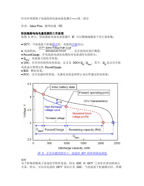
针对多体锂离子电池组的电池电量监测计——第二部分作者:Sihua Wen ,德州仪器 (TI )阻抗跟踪电池电量监测的工作原理如图 3 所示,阻抗跟踪电池电量监测计 IC 可以精确地测量下列主要参数:● OCV :当电池处于松弛模式时,电池的开路电压;● 电池阻抗:,仅在放电时进行测量; ● PassedCharge :在电池放电或充电期间对电荷或库仑的积分;● Q Max :电池最大的化学容量;● SOC :在任何时候的充电状态,定义为 SOC= Q D / Q Max ,其中,Q D 是由完全放电状态计算得出的 PassedCharge ;● RM :剩余电量;● FCC :完全充满时的容量,从满充电状态到终止电压所通过的电荷量;图 3:在有负载的情况下,电池的 OCV 特性和放电曲线SOC对于特殊的锂离子电池化学特性来说,因为 SOC 和 OCV 之间存在密切的相互关系,所以,可以从电池的 OCV 来估计其 SOC 。
当电池处于松弛模式时,所测得的 OCV I 被定义为电池的状态,此时其电流小于一个给定的阀值(如 10mA )且电池的电压稳定。
然后,就可以利用预先定义的 OCV-SOC 关系来确定 SOC 。
这就为后来的放电或充电周期标记了一个最初的电池状态,并且当系统处于低功耗模式时完成,如关机时。
阻抗如图 3 所示,当便携式设备处于正常工作模式时,负载电流会影响电池的放电曲(OCV) 特性的偏差。
当施加负载时,有负载情况下所测得的电固件中实施的电压仿真,就可以计算剩余电量 (RM)。
仿真SOC FINAL 开始,并利用 4% 的 SOC 增量连续地计算同一负载条件下将FI 线并导致开路电压 压与在当前充电状态 (SOC) 下电池化学性质的特定 OCV 之间存在差异,通过测量两个电压之差,可以测量每一个电池的阻抗。
该电压差除以施加的负载电流可以得出阻抗 R 。
此外,阻抗与测量时的温度有关,要将该阻抗代入模型之中才能解决温度效应问题。

深圳市嘉华利电子有限公司TOPWAY EM ENTERPRISE LTD.产品使用说明书Manual产品名称Apellation:蓝牙耳机Bluetooth Earphone 型号Model:17LY71编拟Layout:温家祺 日期Date:2018/10/17复核Review: 日期Date:________审核Auditing: 日期Date:________批准Authorize:日期Date:________1、主控方案 Bluetooth chipset controller :NY0102、产品关键参数Headset Specifications规格列项Items 规格参数说明Description 备 注Remark 蓝牙版本 Bluetooth version V4.2蓝牙协议 Bluetooth profile HFP A2DP HSP AVRCP蓝牙耳机类型 Product type立体声蓝牙耳机Stereo Bluetooth Headphone工作频率 Working Frequency 2.402GHz-2.480GHz产品尺寸 Product dimension TBD产品重量 Product weight TBD额定电池容量 Battery capacity100mAh / 3.7V电池类型 Battery type可充电锂电池Rechargeable Lithium充电电流 Charging current≤70mA充电时间Charging time 1.5 hours关机后静态电流Quiescent current ≤ 0.5uA待机电流Standby current0.3--1mA整机工作电流 Operating current≤10mA播放音乐或通话状态音乐播放时间 Playback music time8-9 hours 测试条件:用iPhone手机,音量为最大音量的70%播放音乐Test condition:used with iPhone playback music for 70﹪ maximum volume通话时间 Talk time8-9 hours待机时间 Standby time Up to 80 hours无障碍蓝牙通话距离Effectivecommunication range正向Forward ≥9M ,背向 Backwards ≥7M无障碍蓝牙播放音乐距离 Effective 正向Forward ≥10M ,背向 Backwards ≥8M接收灵敏度 Receiving sensitivity>-85dBm麦克风 Microphone4015 @ 42+/-3 dB (电容咪头)喇叭Speaker typeΦ9mm (DLBR-09ND06-005)阻抗Impedance16□ ± 15%喇叭声压灵敏度Sound pressure 89± 3dB @1mw 1kHz with IEC318频响范围Frequency response20 - 20, 000 Hz额定输入功率Rated input power 3mW最大输入功率Maximum input power 10mW声道平衡度Channel balance≤ 3dB @ 1kHz失真度Distortion< 5% @ 1kHz 1mW工作温度 Operating temperature-10~+45℃储存温度 Storage temperature-20~+60℃3、产品主要功能特点 Product main function4、产品提示音、LED指示灯状态序号 No功能Function提示音toneLED状态LED status备注Remark1开机Powering on滴 蓝灯快闪Blue LED flashing fast2配对pairing/ 红蓝灯交替闪烁Red and Blue LED flashing alternately3关机Powering off滴 蓝灯闪一下Blue LED flashing once4连接成功ConnectedConnected 蓝灯闪Blue LED flashing5断开连接DisconnectedDisconnected 蓝灯闪Blue LED flashing6来电Incoming call嘟嘟嘟/苹果同步手机铃声蓝灯闪Blue LED flashing7拒接电话Reject call/ 蓝灯闪Blue LED flashing8挂断电话End call嘟 蓝灯闪Blue LED flashing9末码重拨Last number redial/ 蓝灯闪Blue LED flashing10播放音乐Play music/ 蓝灯闪Blue LED flashing11低电提醒Low battery alertLow charge 红灯闪Red light flashing12充电Charging/ 红灯常亮Red LED is lit13充满电Fully charged/ 蓝灯常亮Blue LED is lit14最大音量Maximum Volume滴/15最小音量Minimum Volume/ /5、产品使用功能列表 User Guide序号 No 实现功能Function耳机状态headsetstatus操 作Operation备注Remark1开机/配对Poweringon/pairing关机状态下UnderPowering off长按“Power”键4秒,自动进入配对状态;打开手机蓝牙搜索设备名,点按设备名进入连接Long Press "Power" button for 4 seconds, theHeadphone into POWER ON, then it enterpairing mode, Open mobile phone setting ,searching Bluetooth device name , click devicename and then the headphone connected2关机Powering off开机状态下UnderPowering on长按Power键3秒Long Press“Power”button for 3 seconds 功能特点 描述蓝牙立体声(Stereo 入耳式立体声蓝牙耳机 Bluetooth Headphone蓝牙通话(Talking) 支持使用蓝牙耳机通话 Support talking function电量指示(Battery indication)支持蓝牙耳机的电量在IOS手机上显示 Support battery capacity indication 中/英文切换 无 NC蓝牙配对名称 配对名:17LY713末码重拨Last numberredial待机状态Standby mode双击“Power”键一下Double click on“Power”button once4接听电话Answer call来电中Incoming call短按“Power”键一下Click“Power”button once5 挂断电话End call通话中On calling短按“Power”键一下Click“Power”button once6拒接电话Reject call来电中Incoming call长按“Power”键约2秒Long Press“Power”button for 2 second7低电提醒Low batteryalert开机状态Power On当电池电压低到3.3V时,有提示音When battery voltage less than 3.3V, theHeadphone will be warning and have tone speakout from speaker.8自动关机Automatically poweringoff开机状态UnderPowering on耳机无连接或断开蓝牙连接3分钟耳机将自动关机 Onceheadphone no connection or disconnected over3minutes, Headphone will shut down automatically耳机电池电压低到3.0V时耳机将自动关机Battery voltage less than 3.0V, the Headphone willpower-off automatically.9 充电Charging关机状态下Underpowering off将Micro USB充电线插入充电口即可实现充电Micro USB cable Plug into charging port.10 充电Charging任何开机状态Under anypowering onstatus将Micro USB充电线插入充电口即可实现充电,耳机不会关机。

User GuideCopyright and License© 2016 Copyright HP Development Company, L.P.All rights reserved. Reproduction, adaptation, or translation of this material is prohibited without prior written permission of HP, except as allowed under copyright laws.The information contained in this document is subject to change without notice.The only warranties for HP products and services are set forth in the express warranty statements accompanying such products and services. Nothing herein should be construed as constituting an additional warranty. HP shall not be liable for technical or editorial errors or omissions contained herein.Edition 1, 2/2016Trademark CreditsAdobe®, Acrobat®, and PostScript® are trademarks of Adobe Systems Incorporated. Intel® Core™ is a trademark of Intel Corporation in the U.S. and other countries.Java™ is a US trademark of Sun Microsystems, Inc.Microsoft®, Windows®, Windows® XP, and Windows Vista® are U.S. registered trademarks of Microsoft Corporation.UNIX® is a registered trademark of The Open Group.ENERGY STAR and the ENERGY STAR mark are registered trademarks owned by the U.S. Environmental Protection Agency.Table of contents1 Product basics (1)Product features (2)Environmental features (3)Accessibility features (3)Product views (4)Front left view (4)Front right view (5)Back view (5)Cartridge door view (6)Power on and off (7)Turn the product on (7)Manage power (7)Turn the product off (8)Use the control panel (9)Control panel buttons (9)Control panel home screen (10)Control panel dashboard (11)Control panel application folders (11)Control panel shortcuts (12)Help features (12)Printer information (13)Help animations (13)Quiet Mode (14)To turn Quiet Mode on or off from the control panel (14)To turn Quiet Mode on or off from the EWS (14)2 Connect the product (15)Connect the product to a computer or a network (16)To connect the product using a USB cable (16)To connect the product to a network (17)Supported network protocols (17)Connect the product using a wired network (17)ENWW iiiConnect the product using a wireless network (wireless models only) (17)To connect the product to a wireless network using the Wireless SetupWizard (18)To connect the product to a wireless network using WPS (18)To connect the product to a wireless network manually (19)Use Wi-Fi Direct to connect a computer or device to the product (20)To turn on Wi-Fi Direct (20)To print from a wireless-capable mobile device (20)To print from a wireless-capable computer (Windows) (20)To print from a wireless-capable computer (OS X) (20)Install HP printer software for a wireless product already on the network (22)Open the printer software (Windows) (22)Manage network settings (22)View or change network settings (22)Set or change the product password (23)Manually configure TCP/IP parameters from the control panel (23)Link speed and duplex settings (23)3 Printer management and services (25)HP Embedded Web Server (26)About the EWS (26)About cookies (26)Open the EWS (27)Features (27)Home tab (27)Scan tab (28)Fax tab (29)Web Services tab (29)Network tab (29)Tools tab (29)Settings tab (30)Web Services (31)What are Web Services? (31)HP ePrint (31)Print apps (31)Set Up Web Services (31)Use Web Services (32)HP ePrint (32)Print apps (33)Remove Web Services (34)HP Web Jetadmin software (34)iv ENWWProduct security features (34)Security statements (35)Firewall (35)Security settings (36)Firmware updates (36)HP Printer Assistant in the printer software (Windows) (36)Open the HP Printer Assistant (36)Features (36)Connected tab (37)Print, Scan & Fax tab (37)Shop tab (37)Help tab (38)Tools tab (38)Estimated Levels tab (38)HP Utility (OS X) (38)AirPrint™ (OS X) (38)4 Paper and print media (39)Understand paper use (40)Supported media sizes (41)Supported paper and print media sizes (41)Supported envelope sizes (42)Supported card and label sizes (42)Supported photo media sizes (42)Supported paper types and tray capacity (43)Tray 1 (multipurpose) on left side of the product (43)Tray 2 (default tray) and Tray 3 (accessory tray) (44)Configure trays (44)Load media (45)Load Tray 1 (45)Load Tray 2 (46)Load optional Tray 3 (48)Load envelopes (49)Load letterhead or preprinted forms (51)Load the automatic document feeder (52)Load the scanner (53)Tips for selecting and using paper (55)5 Cartridges (56)HP PageWide cartridges (57)HP policy on non-HP cartridges (57)ENWW vManage cartridges (57)Store cartridges (58)Print with General Office mode (58)Print when a cartridge is at estimated end of life (58)Check the estimated cartridge levels (58)Order cartridges (59)Recycle cartridges (60)Replace cartridges (60)Tips for working with cartridges (62)6 Print (63)Print from a computer (64)To print from a computer (Windows) (64)To print from a computer (OS X) (65)To set up printing shortcuts (Windows) (66)To set up printing presets (OS X) (66)To adjust or manage colors (67)Choose a preset color theme for a print job (67)Adjust the color options for a print job manually (67)Match colors to your computer screen (68)Control access to color printing (69)Print from the control panel (69)Print using job storage (69)To enable job storage (69)Disable or enable job storage (Windows) (69)Disable or enable job storage (OS X) (69)To apply job storage to one or all print jobs (70)Apply job storage to one or all print jobs (Windows) (70)Apply job storage to one or all print jobs (OS X) (71)To print a job stored on the printer (71)To delete a job stored on the printer (71)Print from a USB device (72)Print with NFC (72)Print with HP ePrint (72)Print off site by sending an email with the HP ePrint app (32)Print from an on-site computer or mobile device (73)Print with AirPrint (OS X) (73)Tips for print success (74)Cartridge tips (74)Paper loading tips (74)vi ENWW7 Copy and scan (76)Copy (77)Copy settings (77)Adjust lightness or darkness for copies (77)Select a paper tray and paper size for copies (77)Reduce or enlarge a copy (77)Load and copy identification cards (78)Copy photos (79)Load and copy mixed-size originals (80)Copy on both sides automatically (80)Cancel a copy job (80)Scan (81)Scan to a USB drive (81)Scan to a computer (81)To set up scan to computer (81)Set up scanning to a computer (Windows) (82)Set up scanning to a computer (OS X) (82)To scan to a computer from the control panel (82)Scan to email (82)To set up scan to email (82)To scan a document or photo to email (83)Scan a document or photo to email from the control panel (83)Scan a document or photo to email from the printer software (83)To change account settings (83)Scan to a network folder (83)To set up scan to a network folder (84)Set up scan to a network folder in the EWS (84)Set up scan to a network folder in the HP Printer Assistant (84)To scan to a network folder (84)Scan to a network folder from the control panel (84)Scan to a network folder from the printer software (84)Scan to SharePoint (85)To set up scan to SharePoint (85)To scan to SharePoint (85)Scan using HP scanning software (85)Scan using other software (86)To scan from a TWAIN-compliant program (86)To scan from a WIA-compliant program (86)ENWW viiGuidelines for scanning documents as editable text (87)To scan a document to editable text (Windows) (88)To scan documents as editable text (OS X) (89)Tips for copy and scan success (90)8 Fax (91)Set up fax (92)Connect fax to a telephone line (92)Configure fax settings (92)To configure fax settings from the control panel (92)To configure fax settings using the HP Digital Fax Setup Wizard (Windows) (93)Set up HP Digital Fax (93)HP Digital Fax requirements (93)To set up HP Digital Fax (94)Set up HP Digital Fax (Windows) (94)Set up HP Digital Fax (OS X) (94)Set up HP Digital Fax in the EWS (94)To modify HP Digital Fax settings (94)Modify HP Digital Fax settings (Windows) (94)Modify HP Digital Fax settings (OS X) (94)Modify HP Digital Fax settings in the EWS (94)To turn off HP Digital Fax (95)Fax programs, systems, and software (95)Supported fax programs (95)Supported phone services - analog (95)Alternate phone services - digital (95)DSL (95)PBX (95)ISDN (96)VoIP (96)Set fax settings (96)Send-fax settings (96)Set pauses or flash hooks (96)Set a dialing prefix (97)Set tone-dialing or pulse-dialing (97)Set autoredial and the time between redials (97)Set the light/dark setting (98)Set the default resolution (98)Use cover-page templates (99)viii ENWWSet fax forwarding (99)Block or unblock fax numbers (100)Set the number of rings-to-answer (100)Set distinctive ring (101)Use autoreduction for incoming faxes (102)Set the fax sounds volume (102)Set stamp-received faxes (102)Send a fax (102)Send a fax from the control panel (103)Use speed dials and group-dial entries (103)Send a standard fax from the computer (103)Send a fax from the software (104)Send a fax using monitor dialing (105)Send a fax using printer memory (105)Receive a fax (106)Receive a fax manually (106)Fax memory (107)Reprint a fax (107)Delete faxes from memory (107)Use the phone book (107)Create and edit individual speed-dial entries (108)Create and edit group-dial entries (108)Delete speed-dial entries (108)Use reports (108)Print fax confirmation reports (109)Print fax error reports (110)Print and view the fax log (110)Clear the fax log (110)Print the details of the last fax transaction (111)Print a Caller ID Report (111)View the Call History (111)9 Solve problems (112)Problem-solving checklist (113)Check that the product power is on (113)Check the control panel for error messages (113)Test print functionality (113)Test copy functionality (114)Test the fax-sending functionality (114)Test the fax-receiving functionality (114)ENWW ixTry sending a print job from a computer (114)Test the plug-and-print USB functionality (114)Factors that affect product performance (114)Information pages (115)Factory-set defaults (116)Cleaning routines (116)Clean the printhead (117)Clean the scanner glass strip and platen (117)Clean the document feeder pick rollers and separation pad (118)Clean the touch screen (118)Jams and paper-feed issues (119)The product does not pick up paper (119)The product picks up multiple sheets of paper (119)Prevent paper jams (119)Clear jams (120)Jam locations (120)Clear jams from the document feeder (121)Clear jams in Tray 1 (multipurpose tray) (122)Clear jams in Tray 2 (122)Clear jams in optional Tray 3 (123)Clear jams in the left door (124)Clear jams in the output bin (125)Clear jams in the duplexer (126)Cartridge issues (127)Refilled or remanufactured cartridges (127)Interpret control panel messages for cartridges (127)Cartridge Depleted (127)Cartridge Low (128)Cartridge Very Low (128)Counterfeit or used [color] cartridge installed (128)Do not use SETUP cartridges (128)Genuine HP cartridge installed (128)Incompatible [color] (129)Incompatible cartridges (129)Install [color] cartridge (129)Non-HP cartridges installed (129)Printer Failure (130)Problem with Print System (130)Problem with Printer Preparation (130)Problem with SETUP cartridges (130)Use SETUP cartridges (130)x ENWWUsed [color] installed (131)Printing issues (131)The product does not print (131)The product prints slowly (132)Plug-and-print USB issues (132)The Memory Device Options menu does not open when you insert the USBaccessory (132)The file does not print from the USB storage device (132)The file that you want to print is not listed in the Memory Device Options menu (133)Improve print quality (133)Check for genuine HP cartridges (133)Use paper that meets HP specifications (133)Use the correct paper type setting in the printer driver (134)Change the paper type and size setting (Windows) (134)Change the paper type and size setting (OS X) (134)Use the printer driver that best meets your printing needs (134)Align the printhead (135)Print a print-quality report (135)Scan issues (135)Fax issues (136)Fax troubleshooting checklist (136)Change error correction and fax speed (137)Set the fax-error-correction mode (137)Change the fax speed (137)Fax logs and reports (137)Print individual fax reports (137)Set the fax error report (138)Fax error messages (138)Communication error. (138)Document feeder door is open. Canceled fax. (139)Fax is busy. Canceled send. (139)Fax is busy. Redial pending. (139)Fax receive error. (140)Fax Send error. (140)Fax storage is full. Canceling the fax receive. (141)Fax storage is full. Canceling the fax send. (141)No dial tone. (141)No fax answer. Canceled send. (142)No fax answer. Redial pending. (142)No fax detected. (142)Solve problems sending faxes (143)ENWW xiAn error message displays on the control panel (143)Document feeder paper jam (143)Scanner error (143)The control panel displays a Ready message with no attempt to send the fax. (143)The control panel displays the message "Receiving Page 1" and does not progressbeyond that message (144)Faxes can be received, but not sent (144)Unable to use fax functions from the control panel (144)Unable to use speed dials (144)Unable to use group dials (144)Receive a recorded error message from the phone company when trying to senda fax (145)Unable to send a fax when a phone is connected to the product (145)Solve problems receiving faxes (145)An error message displays on the control panel (145)The fax does not respond (145)Voice mail is available on the fax line (145)The product is connected to a DSL phone service (146)The product uses a fax over IP or VoIP phone service (146)Sender receives a busy signal (146)A handset is connected to the product (146)A phone line splitter is being used (146)Cannot send or receive a fax on a PBX line (146)Solve general fax problems (146)Faxes are sending slowly (146)Fax quality is poor (147)Fax cuts off or prints on two pages (147)Connectivity issues (147)Solve USB direct-connect problems (147)Solve network problems (148)Poor physical connection (148)The computer is using the incorrect IP address for the product (148)The computer is unable to communicate with the product (148)The product is using incorrect link and duplex settings for the network (149)New software programs might be causing compatibility problems (149)The computer or workstation might be set up incorrectly (149)The product is disabled, or other network settings are incorrect (149)Wireless network issues (149)Wireless connectivity checklist (149)The product does not print, and the computer has a third-party firewall installed (150)The wireless connection does not work after moving the wireless router or product (150)xii ENWWCannot connect more computers to the wireless product (150)The wireless product loses communication when connected to a VPN (151)The network does not appear in the wireless networks list (151)The wireless network is not functioning (151)Product software issues (Windows) (151)Product software issues (OS X) (153)The printer driver is not listed in the Print & Scan list (153)The product name does not appear in the product list in the Print & Scan list (153)The printer driver does not automatically set up the selected product in the Print & Scan list (153)A print job was not sent to the product that you wanted (153)When connected with a USB cable, the product does not appear in the Print & Scan list afterthe driver is selected. (153)You are using a generic printer driver when using a USB connection (154)10 Service and support (155)Customer support (156)HP limited warranty statement (157)UK, Ireland, and Malta (158)Austria, Belgium, Germany, and Luxemburg (158)Belgium, France, and Luxemburg (159)Italy (160)Spain (160)Denmark (161)Norway (161)Sweden (161)Portugal (162)Greece and Cyprus (162)Hungary (162)Czech Republic (163)Slovakia (163)Poland (163)Bulgaria (164)Romania (164)Belgium and the Netherlands (164)Finland (165)Slovenia (165)Croatia (165)Latvia (165)Lithuania (166)Estonia (166)Russia (166)ENWW xiiiAppendix A Technical information (167)Product specifications (168)Print specifications (168)Physical specifications (168)Power consumption and electrical specifications (168)Acoustic emission specifications (168)Environmental specifications (168)Environmental product stewardship program (170)Protecting the environment (171)Ozone production (171)Power consumption (171)European Union Commission Regulation 1275/2008 (171)Paper (171)HP PageWide printing supplies (171)Plastics (171)Electronic hardware recycling (172)Material restrictions (172)General battery information (172)Battery disposal in Taiwan (172)California Perchlorate Material Notice (172)EU Battery Directive (172)Battery notice for Brazil (173)Chemical substances (173)EPEAT (173)Disposal of waste equipment by users (173)Toxic and hazardous substance table (China) (174)Restriction on hazardous substances statement (Turkey) (174)Restriction on hazardous substances statement (Ukraine) (174)Restriction of hazardous substance statement (India) (174)China energy label for printer, fax, and copier (175)China SEPA Eco Label user information (175)Regulatory information (176)Regulatory notices (176)Regulatory model identification number (176)FCC statement (176)VCCI statement (Japan) (177)Power cord instructions (177)Power cord statement (Japan) (177)EMC statement (Korea) (177)Visual display workplaces statement for Germany (177)European Union Regulatory Notice (178)xiv ENWWEuropean Union Regulatory Notice (178)Wireless models only (178)Models with fax capability only (178)Additional statements for telecom (fax) products (179)New Zealand telecom statements (179)Additional FCC statement for telecom products (US) (179)Industry Canada CS-03 requirements (180)Notice to users of the Canadian telephone network (181)Australia wired fax statement (181)Notice to users of the German telephone network (181)Additional statements for wireless products (182)Exposure to radio frequency radiation (182)Notice to users in Brazil (182)Canadian statements (182)Japan statement (183)Notice to users in Korea (183)Taiwan statement (183)Mexico statement (183)Index (184)ENWW xvxvi ENWW1Product basics●Product features●Product views●Power on and off●Use the control panel●Quiet ModeENWW1Product featuresPageWide Pro MFP 477dnD3Q19A, D3Q19B, D3Q19C,D3Q19D Tray capacity (75 GSM or 20–lb Bond paper)●Tray 1: 50 sheets ●Tray 2: 500 sheets ●Optional Tray 3: 500 sheets ●Automatic Document Feeder(ADF): 50 sheets●Standard output bin: 300sheetsPrint ●Simplex speeds up to 40 pagesper minute (ppm) for both color and black with Professional quality●Duplex speeds up to 21 ppmfor both color and black with Professional quality●Up to 55 ppm in General Officemode●Walkup Plug-and-Print USBDevice port●Walkup printing of MS Officedocuments Copy ●Simplex speeds up to 40 ppm in black and color ●Single-pass, two-sided copying for speeds up to 26 ppm in black and color ●50-sheet ADF supports page sizes up to 356 mm (14.0 in) in length and 216 mm (8.5 in) in width Scan●Duplex speeds up to 26 ppm for both color and black ●Scan to walkup USB device, email address, network folder, or SharePoint site ●Glass supports page sizes up to 356 mm (14.0 in) in length and up to 216 mm (8.5 in) in width ●HP software enables scanning a document to a file that can be edited ●Compatible with TWAIN, WIA, and WS-Scan programs Fax●Fax to email address ornetwork folder●Fax from walkup control panelor from program on connected computer●Fax archive, fax log, junk-faxblocking, non-volatile fax memory, fax redirect featureConnectivity ●802.3 LAN (10/100) Ethernet port ●Host USB Type A and Type B ports (back)●USB 2.0 Device port (front)PageWide Pro MFP 477dw D3Q20A, D3Q20B, D3Q20C, D3Q20D Has the same features as the PageWide Pro MFP 477dn, and includes the following:●Embedded wireless capability ●802.11n 5GHz dual bandsupport●HP ePrint—send documents tothe product email address for printing●HP Wireless Direct support ●NFC-enabled (Near FieldCommunications); walkup printing from smart phones and tablets●Scan to smart phone 2Chapter 1 Product basics ENWWEnvironmental featuresFeature Environmental benefitDuplex printing Automatic duplex printing is available on all models of HP PageWide Pro MFP477dn/dw series. Duplex printing saves the environment and saves you money.Print multiple pages per sheet Save paper by printing two or more pages of a document side-by-side on onesheet of paper. Access this feature through the printer driver.Copies multiple pages per sheet Save paper by copying two pages of an original document side-by-side on onesheet of paper.Recycling Reduce waste by using recycled paper.Recycle cartridges by using the HP Planet Partners return process.Energy savings Sleep modes and timer options enable this product to quickly go into reducedpower states when not printing, thus saving energy. Accessibility featuresThe product includes several features that aid users with limited vision, hearing, dexterity or strength.●Online user guide that is compatible with text screen-readers.●Cartridges can be installed and removed using one hand.●All doors and covers can be opened using one hand.ENWW Product features3Product views●Front left view●Front right view●Back view●Cartridge door viewFront left viewLabel Description1USB device connection port2Cartridge door3Tray 1 extension4Tray 15Power button6Tray 2–main paper tray7Control panel8Scanner glass4Chapter 1 Product basics ENWWFront right viewLabel Description1Automatic document feeder (ADF) cover2Main output door3ADF paper guides4ADF loading area5ADF output bin6ADF output bin stop7Main output bin stop8Main output binBack viewLabel Description1Ethernet connection port2Fax connection ports3USB Type A and USB Type B ports4Power cord connectionENWW Product views5Label Description5Left door6DuplexerCartridge door viewLabel Description1Cartridge slots2Product serial number and product number3Cartridge part numbers6Chapter 1 Product basics ENWWPower on and offNOTICE:To prevent damage to the product, use only the power cord that is provided with the product.●Turn the product on●Manage power●Turn the product offTurn the product on1.Connect the power cord that is provided with the product to the connection port on the back of theproduct.2.Connect the power cord to a wall outlet with an adequate voltage rating.NOTE:Make sure that your power source is adequate for the product voltage rating. The product useseither 100-240 Vac or 200-240 Vac and 50/60 Hz.3.Press and release the power button on the front of the product.Manage powerHP PageWide Pro MFP 477dn/dw series printers include power-management features that can help reducepower consumption and save energy.●Sleep Mode puts the product in a reduced power-consumption state if it has been idle for a specificlength of time. You can set the length of time before the product enters Sleep Mode from the controlpanel.●Schedule On/Off enables you to turn the product on or off automatically at days and time that you setfrom the control panel. For example, you can set the product to turn off at 6 p.m. on Monday throughFriday.Set the Sleep Mode time1.Open the control panel dashboard (swipe the dashboard tab at the top of any screen downward, ortouch the dashboard area on the home screen).2.On the control panel dashboard, touch .ENWW Power on and off73.Touch Power Management, and then touch Sleep Mode.4.Select one of the time-interval options.The product switches into a reduced power-consumption state when it has been idle for the amount of timethat you select.Schedule the product to turn on or off1.Open the control panel dashboard (swipe the dashboard tab at the top of any screen downward, ortouch the dashboard area on the home screen).2.On the control panel dashboard, touch .3.Touch Power Management, and then touch Schedule Printer On/Off.4.Turn the Schedule On or Schedule Off option on.5.Select the Schedule On or Schedule Off options at the bottom of the screen, and then select the day andtime that you want to schedule.The product switches on or off at the time you select on the day you select.NOTE:The product cannot receive faxes when it is turned off. Faxes sent during a scheduled off interval willprint when the product is turned on.Turn the product offNOTICE:Do not turn off the product if a cartridge is missing. Damage to the product can result.▲Press and release the power button on the front of the product to turn off your HP PageWide Pro MFP 477dn/dw series printer.A warning message appears on the control panel if you attempt to turn the product off when one ormore cartridges are missing.NOTICE:To prevent print-quality problems, turn off the product by using the power button on the frontonly. Do not unplug the product, turn off the powerstrip, or use any other method.8Chapter 1 Product basics ENWWUse the control panel●Control panel buttons●Control panel home screen●Control panel dashboard●Control panel application folders●Control panel shortcuts●Help featuresNOTE:The small text on the control panel is not designed for prolonged viewing.Control panel buttonsButtons and indicator lights on the control panel of HP PageWide Pro MFP 477dn/dw series printers appear litwhen their function is available, and are darkened if their function is not available.1Home button.Touch to view the control panel home screen.2Wireless network indicator.Solid blue when the product is connected to a wireless network. Blinks when the product is searching for awireless connection. Off when the product is connected to a wired network or by a USB cable.3NFC (Near Field Communications) indicator.The product can be enabled for walkup printing from tablets and smart phones.4Back or Cancel button.Touch to return to the previous screen, or to cancel the current process.5Help button.Touch to view the Help menu options.ENWW Use the control panel9。

InBody 270Timeless style, yet significant feature changesInBody 270One of the key features of the InBody 270 is the lightweight, foldable structure for easy installation and safe relocation. The device weighs only 14kg, perfect for mobile scanning businesses and Personal Trainers on the move. Plus, has a specially designed bag to maximise portability and to ensure the device stays safe during transportation.The InBody 270 uses 10 impedance measurements by using 2 different frequencies to measure the 5 segments of the body to provide over 25 parameters relevant and specific to body composition.This device allows you or your trainer/health professional to regularly monitor your level of body fat, lean muscle mass and muscular development so you can understand howyour diet, lifestyle and training regime are influencing your overall body composition.Developed based on professionals experience• User friendly interface, with minimum inputs required to complete the test• The InBody 270 can save up to 100,000 results using the member ID feature• Easily transfer results in a CSV file to a USB memory stick• Easy to carry, install and operate• The device is only 14kg so it can maximise your mobility• Segmental Lean Analysis, shows muscle adequacy of each segment of the body separatelyUniversally dominating technology protected by global patents• Visceral Fat Level (VFL) which indicates intestinal balance, if unbalanced, can be related to many hazardous lifestyle factors.• ECW Ratio indicates water balance and helps to determine nutritional status of an individual• Segmental Lean Analysis shows muscle adequacy of each segment of the bodyseparatelyMonitor your body’s statuson the go with your InBodydata delivered right to yourmobile device.Connect with friends andfamily. Keep each other incheck and on track.Track your scan historyand visualise progressingtowards your goals.Stay connected with yourtrainer, keeping you ontrack and motivated.Cloud Database ManagementLookin’Body WebManage all of your member's InBody data from any computer anytime, anywhere.Track client progressSet target goalsAccess client historyConnect with clients and keep notesPowerful AnalyticsAnalytics takes the guesswork out. Running a fitness challenge and need to award a winner? Use the data in Lookin'Body Web to easily identify member's who have gained the most lean muscle mass and lost the most body fat.1 year subscription included with all machine purchases InBody Mobile App (Available Free from the App Store)Stay connected with your clients, keeping them on track and motivated. Through the use of ourmobile app, your clients can keep track of their goals and monitor their progress.Key SpecificationsFeature SpecificationsOther SpecificationsResult SheetDevice ComparisonBSM370 StadiometerThe BSM370 Stadiometer is a precise height measuring device. Featuring, an ergonomically designed touch bar and precise measurement sensor. This automatically measure the user’s height while standing on the scale.Automatic portable stadiometer• Measures height, weight, and BMI • Connect via RS32 cable to all InBody devices to allow precise heightmeasurement via automatic data transfer • A lightweight 14kg allows for easy portability• Features two smooth-gliding wheels for effortless mobility, both indoors and out • Easily moved in it’s ready-to-use position or folded into a convenient space saving unit that will fit in tight spaces • This BSM370 Stadiometer can be integrated with other InBody devicesproviding the complete InBody packageSpecificationsFlexible cuff guide ring that allows for accurate measurement of larger arm sizes (18 ~ 42cm)Comfortable and painless measurement with the air pouch insulation and the cuffBiotechnological design that ensures the right posture Wide LED screen for easy checking of all results (systolic, diastolic, and pulse rate), LED light guides the process of measurement and indicates current time‘Print’ button for an easier test. Larger buttons easier recognitionHigh-speed thermal printer with automatic cutter for a clean Emergency closing during measuring process if necessary1567135mm 123456788432BPBIO320 Blood Pressure MonitorThe BPBIO320 fully automated blood pressure monitor provides a highly effective and easy way of measuring blood pressure. It can be a stand-alone product or in connection with your InBody device. It provides a simple single step measurement with voice guidance and specific elbow point positioning. This allows the best test posture possible. For clinical and non-clinical environments, the BPBIO320 delivers.SpecificationsBlood Pressure Monitor $3,145 + GSTInBody 270 Device PackagePackage InclusionsThis package includes the items pictured here, plus the following items:InBody 270 Package $16,700 + GST+ Postage & handlingInBody Academy This one day intensive training course will cover:InBody’s patented technologyHow to set up and use your InBodyInterpretation of an InBody scanBusiness & Marketing tipsPlus, much more.Location: Gold Coast ShowroomOnline TrainingCreating Excellence in Body CompositionKorea Food & DrugGet the InBody App。
Glider Flying Handbook2013U.S. Department of TransportationFEDERAL AVIATION ADMINISTRATIONFlight Standards Servicei iPrefaceThe Glider Flying Handbook is designed as a technical manual for applicants who are preparing for glider category rating and for currently certificated glider pilots who wish to improve their knowledge. Certificated flight instructors will find this handbook a valuable training aid, since detailed coverage of aeronautical decision-making, components and systems, aerodynamics, flight instruments, performance limitations, ground operations, flight maneuvers, traffic patterns, emergencies, soaring weather, soaring techniques, and cross-country flight is included. Topics such as radio navigation and communication, use of flight information publications, and regulations are available in other Federal Aviation Administration (FAA) publications.The discussion and explanations reflect the most commonly used practices and principles. Occasionally, the word “must” or similar language is used where the desired action is deemed critical. The use of such language is not intended to add to, interpret, or relieve a duty imposed by Title 14 of the Code of Federal Regulations (14 CFR). Persons working towards a glider rating are advised to review the references from the applicable practical test standards (FAA-G-8082-4, Sport Pilot and Flight Instructor with a Sport Pilot Rating Knowledge Test Guide, FAA-G-8082-5, Commercial Pilot Knowledge Test Guide, and FAA-G-8082-17, Recreational Pilot and Private Pilot Knowledge Test Guide). Resources for study include FAA-H-8083-25, Pilot’s Handbook of Aeronautical Knowledge, FAA-H-8083-2, Risk Management Handbook, and Advisory Circular (AC) 00-6, Aviation Weather For Pilots and Flight Operations Personnel, AC 00-45, Aviation Weather Services, as these documents contain basic material not duplicated herein. All beginning applicants should refer to FAA-H-8083-25, Pilot’s Handbook of Aeronautical Knowledge, for study and basic library reference.It is essential for persons using this handbook to become familiar with and apply the pertinent parts of 14 CFR and the Aeronautical Information Manual (AIM). The AIM is available online at . The current Flight Standards Service airman training and testing material and learning statements for all airman certificates and ratings can be obtained from .This handbook supersedes FAA-H-8083-13, Glider Flying Handbook, dated 2003. Always select the latest edition of any publication and check the website for errata pages and listing of changes to FAA educational publications developed by the FAA’s Airman Testing Standards Branch, AFS-630.This handbook is available for download, in PDF format, from .This handbook is published by the United States Department of Transportation, Federal Aviation Administration, Airman Testing Standards Branch, AFS-630, P.O. Box 25082, Oklahoma City, OK 73125.Comments regarding this publication should be sent, in email form, to the following address:********************************************John M. AllenDirector, Flight Standards Serviceiiii vAcknowledgmentsThe Glider Flying Handbook was produced by the Federal Aviation Administration (FAA) with the assistance of Safety Research Corporation of America (SRCA). The FAA wishes to acknowledge the following contributors: Sue Telford of Telford Fishing & Hunting Services for images used in Chapter 1JerryZieba () for images used in Chapter 2Tim Mara () for images used in Chapters 2 and 12Uli Kremer of Alexander Schleicher GmbH & Co for images used in Chapter 2Richard Lancaster () for images and content used in Chapter 3Dave Nadler of Nadler & Associates for images used in Chapter 6Dave McConeghey for images used in Chapter 6John Brandon (www.raa.asn.au) for images and content used in Chapter 7Patrick Panzera () for images used in Chapter 8Jeff Haby (www.theweatherprediction) for images used in Chapter 8National Soaring Museum () for content used in Chapter 9Bill Elliot () for images used in Chapter 12.Tiffany Fidler for images used in Chapter 12.Additional appreciation is extended to the Soaring Society of America, Inc. (), the Soaring Safety Foundation, and Mr. Brad Temeyer and Mr. Bill Martin from the National Oceanic and Atmospheric Administration (NOAA) for their technical support and input.vv iPreface (iii)Acknowledgments (v)Table of Contents (vii)Chapter 1Gliders and Sailplanes ........................................1-1 Introduction....................................................................1-1 Gliders—The Early Years ..............................................1-2 Glider or Sailplane? .......................................................1-3 Glider Pilot Schools ......................................................1-4 14 CFR Part 141 Pilot Schools ...................................1-5 14 CFR Part 61 Instruction ........................................1-5 Glider Certificate Eligibility Requirements ...................1-5 Common Glider Concepts ..............................................1-6 Terminology...............................................................1-6 Converting Metric Distance to Feet ...........................1-6 Chapter 2Components and Systems .................................2-1 Introduction....................................................................2-1 Glider Design .................................................................2-2 The Fuselage ..................................................................2-4 Wings and Components .............................................2-4 Lift/Drag Devices ...........................................................2-5 Empennage .....................................................................2-6 Towhook Devices .......................................................2-7 Powerplant .....................................................................2-7 Self-Launching Gliders .............................................2-7 Sustainer Engines .......................................................2-8 Landing Gear .................................................................2-8 Wheel Brakes .............................................................2-8 Chapter 3Aerodynamics of Flight .......................................3-1 Introduction....................................................................3-1 Forces of Flight..............................................................3-2 Newton’s Third Law of Motion .................................3-2 Lift ..............................................................................3-2The Effects of Drag on a Glider .....................................3-3 Parasite Drag ..............................................................3-3 Form Drag ...............................................................3-3 Skin Friction Drag ..................................................3-3 Interference Drag ....................................................3-5 Total Drag...................................................................3-6 Wing Planform ...........................................................3-6 Elliptical Wing ........................................................3-6 Rectangular Wing ...................................................3-7 Tapered Wing .........................................................3-7 Swept-Forward Wing ..............................................3-7 Washout ..................................................................3-7 Glide Ratio .................................................................3-8 Aspect Ratio ............................................................3-9 Weight ........................................................................3-9 Thrust .........................................................................3-9 Three Axes of Rotation ..................................................3-9 Stability ........................................................................3-10 Flutter .......................................................................3-11 Lateral Stability ........................................................3-12 Turning Flight ..............................................................3-13 Load Factors .................................................................3-13 Radius of Turn ..........................................................3-14 Turn Coordination ....................................................3-15 Slips ..........................................................................3-15 Forward Slip .........................................................3-16 Sideslip .................................................................3-17 Spins .........................................................................3-17 Ground Effect ...............................................................3-19 Chapter 4Flight Instruments ...............................................4-1 Introduction....................................................................4-1 Pitot-Static Instruments ..................................................4-2 Impact and Static Pressure Lines................................4-2 Airspeed Indicator ......................................................4-2 The Effects of Altitude on the AirspeedIndicator..................................................................4-3 Types of Airspeed ...................................................4-3Table of ContentsviiAirspeed Indicator Markings ......................................4-5 Other Airspeed Limitations ........................................4-6 Altimeter .....................................................................4-6 Principles of Operation ...........................................4-6 Effect of Nonstandard Pressure andTemperature............................................................4-7 Setting the Altimeter (Kollsman Window) .............4-9 Types of Altitude ......................................................4-10 Variometer................................................................4-11 Total Energy System .............................................4-14 Netto .....................................................................4-14 Electronic Flight Computers ....................................4-15 Magnetic Compass .......................................................4-16 Yaw String ................................................................4-16 Inclinometer..............................................................4-16 Gyroscopic Instruments ...............................................4-17 G-Meter ........................................................................4-17 FLARM Collision Avoidance System .........................4-18 Chapter 5Glider Performance .............................................5-1 Introduction....................................................................5-1 Factors Affecting Performance ......................................5-2 High and Low Density Altitude Conditions ...........5-2 Atmospheric Pressure .............................................5-2 Altitude ...................................................................5-3 Temperature............................................................5-3 Wind ...........................................................................5-3 Weight ........................................................................5-5 Rate of Climb .................................................................5-7 Flight Manuals and Placards ..........................................5-8 Placards ......................................................................5-8 Performance Information ...........................................5-8 Glider Polars ...............................................................5-8 Weight and Balance Information .............................5-10 Limitations ...............................................................5-10 Weight and Balance .....................................................5-12 Center of Gravity ......................................................5-12 Problems Associated With CG Forward ofForward Limit .......................................................5-12 Problems Associated With CG Aft of Aft Limit ..5-13 Sample Weight and Balance Problems ....................5-13 Ballast ..........................................................................5-14 Chapter 6Preflight and Ground Operations .......................6-1 Introduction....................................................................6-1 Assembly and Storage Techniques ................................6-2 Trailering....................................................................6-3 Tiedown and Securing ................................................6-4Water Ballast ..............................................................6-4 Ground Handling........................................................6-4 Launch Equipment Inspection ....................................6-5 Glider Preflight Inspection .........................................6-6 Prelaunch Checklist ....................................................6-7 Glider Care .....................................................................6-7 Preventive Maintenance .............................................6-8 Chapter 7Launch and Recovery Procedures and Flight Maneuvers ............................................................7-1 Introduction....................................................................7-1 Aerotow Takeoff Procedures .........................................7-2 Signals ........................................................................7-2 Prelaunch Signals ....................................................7-2 Inflight Signals ........................................................7-3 Takeoff Procedures and Techniques ..........................7-3 Normal Assisted Takeoff............................................7-4 Unassisted Takeoff.....................................................7-5 Crosswind Takeoff .....................................................7-5 Assisted ...................................................................7-5 Unassisted...............................................................7-6 Aerotow Climb-Out ....................................................7-6 Aerotow Release.........................................................7-8 Slack Line ...................................................................7-9 Boxing the Wake ......................................................7-10 Ground Launch Takeoff Procedures ............................7-11 CG Hooks .................................................................7-11 Signals ......................................................................7-11 Prelaunch Signals (Winch/Automobile) ...............7-11 Inflight Signals ......................................................7-12 Tow Speeds ..............................................................7-12 Automobile Launch ..................................................7-14 Crosswind Takeoff and Climb .................................7-14 Normal Into-the-Wind Launch .................................7-15 Climb-Out and Release Procedures ..........................7-16 Self-Launch Takeoff Procedures ..............................7-17 Preparation and Engine Start ....................................7-17 Taxiing .....................................................................7-18 Pretakeoff Check ......................................................7-18 Normal Takeoff ........................................................7-19 Crosswind Takeoff ...................................................7-19 Climb-Out and Shutdown Procedures ......................7-19 Landing .....................................................................7-21 Gliderport/Airport Traffic Patterns and Operations .....7-22 Normal Approach and Landing ................................7-22 Crosswind Landing ..................................................7-25 Slips ..........................................................................7-25 Downwind Landing ..................................................7-27 After Landing and Securing .....................................7-27viiiPerformance Maneuvers ..............................................7-27 Straight Glides ..........................................................7-27 Turns.........................................................................7-28 Roll-In ...................................................................7-29 Roll-Out ................................................................7-30 Steep Turns ...........................................................7-31 Maneuvering at Minimum Controllable Airspeed ...7-31 Stall Recognition and Recovery ...............................7-32 Secondary Stalls ....................................................7-34 Accelerated Stalls .................................................7-34 Crossed-Control Stalls ..........................................7-35 Operating Airspeeds .....................................................7-36 Minimum Sink Airspeed ..........................................7-36 Best Glide Airspeed..................................................7-37 Speed to Fly ..............................................................7-37 Chapter 8Abnormal and Emergency Procedures .............8-1 Introduction....................................................................8-1 Porpoising ......................................................................8-2 Pilot-Induced Oscillations (PIOs) ..............................8-2 PIOs During Launch ...................................................8-2 Factors Influencing PIOs ........................................8-2 Improper Elevator Trim Setting ..............................8-3 Improper Wing Flaps Setting ..................................8-3 Pilot-Induced Roll Oscillations During Launch .........8-3 Pilot-Induced Yaw Oscillations During Launch ........8-4 Gust-Induced Oscillations ..............................................8-5 Vertical Gusts During High-Speed Cruise .................8-5 Pilot-Induced Pitch Oscillations During Landing ......8-6 Glider-Induced Oscillations ...........................................8-6 Pitch Influence of the Glider Towhook Position ........8-6 Self-Launching Glider Oscillations During Powered Flight ...........................................................8-7 Nosewheel Glider Oscillations During Launchesand Landings ..............................................................8-7 Tailwheel/Tailskid Equipped Glider Oscillations During Launches and Landings ..................................8-8 Aerotow Abnormal and Emergency Procedures ............8-8 Abnormal Procedures .................................................8-8 Towing Failures........................................................8-10 Tow Failure With Runway To Land and Stop ......8-11 Tow Failure Without Runway To Land BelowReturning Altitude ................................................8-11 Tow Failure Above Return to Runway Altitude ...8-11 Tow Failure Above 800' AGL ..............................8-12 Tow Failure Above Traffic Pattern Altitude .........8-13 Slack Line .................................................................8-13 Ground Launch Abnormal and Emergency Procedures ....................................................................8-14 Abnormal Procedures ...............................................8-14 Emergency Procedures .............................................8-14 Self-Launch Takeoff Emergency Procedures ..............8-15 Emergency Procedures .............................................8-15 Spiral Dives ..................................................................8-15 Spins .............................................................................8-15 Entry Phase ...............................................................8-17 Incipient Phase .........................................................8-17 Developed Phase ......................................................8-17 Recovery Phase ........................................................8-17 Off-Field Landing Procedures .....................................8-18 Afterlanding Off Field .............................................8-20 Off-Field Landing Without Injury ........................8-20 Off-Field Landing With Injury .............................8-20 System and Equipment Malfunctions ..........................8-20 Flight Instrument Malfunctions ................................8-20 Airspeed Indicator Malfunctions ..........................8-21 Altimeter Malfunctions .........................................8-21 Variometer Malfunctions ......................................8-21 Compass Malfunctions .........................................8-21 Glider Canopy Malfunctions ....................................8-21 Broken Glider Canopy ..........................................8-22 Frosted Glider Canopy ..........................................8-22 Water Ballast Malfunctions ......................................8-22 Retractable Landing Gear Malfunctions ..................8-22 Primary Flight Control Systems ...............................8-22 Elevator Malfunctions ..........................................8-22 Aileron Malfunctions ............................................8-23 Rudder Malfunctions ............................................8-24 Secondary Flight Controls Systems .........................8-24 Elevator Trim Malfunctions .................................8-24 Spoiler/Dive Brake Malfunctions .........................8-24 Miscellaneous Flight System Malfunctions .................8-25 Towhook Malfunctions ............................................8-25 Oxygen System Malfunctions ..................................8-25 Drogue Chute Malfunctions .....................................8-25 Self-Launching Gliders ................................................8-26 Self-Launching/Sustainer Glider Engine Failure During Takeoff or Climb ..........................................8-26 Inability to Restart a Self-Launching/SustainerGlider Engine While Airborne .................................8-27 Self-Launching Glider Propeller Malfunctions ........8-27 Self-Launching Glider Electrical System Malfunctions .............................................................8-27 In-flight Fire .............................................................8-28 Emergency Equipment and Survival Gear ...................8-28 Survival Gear Checklists ..........................................8-28 Food and Water ........................................................8-28ixClothing ....................................................................8-28 Communication ........................................................8-29 Navigation Equipment ..............................................8-29 Medical Equipment ..................................................8-29 Stowage ....................................................................8-30 Parachute ..................................................................8-30 Oxygen System Malfunctions ..................................8-30 Accident Prevention .....................................................8-30 Chapter 9Soaring Weather ..................................................9-1 Introduction....................................................................9-1 The Atmosphere .............................................................9-2 Composition ...............................................................9-2 Properties ....................................................................9-2 Temperature............................................................9-2 Density ....................................................................9-2 Pressure ...................................................................9-2 Standard Atmosphere .................................................9-3 Layers of the Atmosphere ..........................................9-4 Scale of Weather Events ................................................9-4 Thermal Soaring Weather ..............................................9-6 Thermal Shape and Structure .....................................9-6 Atmospheric Stability .................................................9-7 Air Masses Conducive to Thermal Soaring ...................9-9 Cloud Streets ..............................................................9-9 Thermal Waves...........................................................9-9 Thunderstorms..........................................................9-10 Lifted Index ..........................................................9-12 K-Index .................................................................9-12 Weather for Slope Soaring .......................................9-14 Mechanism for Wave Formation ..............................9-16 Lift Due to Convergence ..........................................9-19 Obtaining Weather Information ...................................9-21 Preflight Weather Briefing........................................9-21 Weather-ReIated Information ..................................9-21 Interpreting Weather Charts, Reports, andForecasts ......................................................................9-23 Graphic Weather Charts ...........................................9-23 Winds and Temperatures Aloft Forecast ..............9-23 Composite Moisture Stability Chart .....................9-24 Chapter 10Soaring Techniques ..........................................10-1 Introduction..................................................................10-1 Thermal Soaring ...........................................................10-2 Locating Thermals ....................................................10-2 Cumulus Clouds ...................................................10-2 Other Indicators of Thermals ................................10-3 Wind .....................................................................10-4 The Big Picture .....................................................10-5Entering a Thermal ..............................................10-5 Inside a Thermal.......................................................10-6 Bank Angle ...........................................................10-6 Speed .....................................................................10-6 Centering ...............................................................10-7 Collision Avoidance ................................................10-9 Exiting a Thermal .....................................................10-9 Atypical Thermals ..................................................10-10 Ridge/Slope Soaring ..................................................10-10 Traps ......................................................................10-10 Procedures for Safe Flying .....................................10-12 Bowls and Spurs .....................................................10-13 Slope Lift ................................................................10-13 Obstructions ...........................................................10-14 Tips and Techniques ...............................................10-15 Wave Soaring .............................................................10-16 Preflight Preparation ...............................................10-17 Getting Into the Wave ............................................10-18 Flying in the Wave .................................................10-20 Soaring Convergence Zones ...................................10-23 Combined Sources of Updrafts ..............................10-24 Chapter 11Cross-Country Soaring .....................................11-1 Introduction..................................................................11-1 Flight Preparation and Planning ...................................11-2 Personal and Special Equipment ..................................11-3 Navigation ....................................................................11-5 Using the Plotter .......................................................11-5 A Sample Cross-Country Flight ...............................11-5 Navigation Using GPS .............................................11-8 Cross-Country Techniques ...........................................11-9 Soaring Faster and Farther .........................................11-11 Height Bands ..........................................................11-11 Tips and Techniques ...............................................11-12 Special Situations .......................................................11-14 Course Deviations ..................................................11-14 Lost Procedures ......................................................11-14 Cross-Country Flight in a Self-Launching Glider .....11-15 High-Performance Glider Operations and Considerations ............................................................11-16 Glider Complexity ..................................................11-16 Water Ballast ..........................................................11-17 Cross-Country Flight Using Other Lift Sources ........11-17 Chapter 12Towing ................................................................12-1 Introduction..................................................................12-1 Equipment Inspections and Operational Checks .........12-2 Tow Hook ................................................................12-2 Schweizer Tow Hook ...........................................12-2x。
Application ReportSLUA623–October2011bq20z655to bq20z655-R1Change Document Garry Elder PMP-BMS NotebookIntroductionThe bq20z655is an SMBus Gas Gauge enabled with Impedance Track™Technology that has the ability to drive an LCD display of RSOC,as well as a traditional LED display.The bq20z655-R1provides three enhancements to improve system level interactions.1.Improved FET Turn-On Time Upon Exit of Shutdown2.RemainingCapacity()and FullChargeCapacity()Update Change3.SBS1.1Master Mode Bus Start Collision UpdateFor information on the features of the bq20z655device,refer to the bq20z655Technical ReferenceManual(SLUU493).This change document provides all of the details on the bq20z655-R1enhancements to the bq20z655device.For further information on the bq20z655-R1device,refer to the bq20z655-R1Data Sheet(SLUSAN9).1Improved FET Turn-On Time Upon Exit of ShutdownAn option was added to shorten the time it takes for the charge and discharge FETs to turn on coming out of shutdown or reset.If the[FAST_FET]bit in Operation cfg C is set to1,the FETs turn on in less than1.5s after power-on reset.If copper deposition(SUV)is configured for use at power-on reset,then FETsare off for SUV time.To use Fast FET turn-on time,SUV should be configured to be used in NormalMode,not at start up.If the Fast FET turn-on time option is used,initial capacity estimation may be off by 10–30%due to initialization of IT data with current.However,this would be corrected upon a Qmaxupdate.Two data flash parameters,Transient Factor Charge and Transient Factor Discharge,are added to allow the adjustment of resistance due to transient voltage readings with Fast FET turn on.Transient Factor Discharge and Transient Factor ChargeValue from0to255(default180)has meaning as a factor from0to1to adjust resistanceSo:R_adj=R*TransFactorDisch/256.Class Subclass Name Units Type DefaultTransient FactorGas Gauging IT Cfg(93)—Hex180ChargeTransient FactorGas Gauging IT Cfg(94)—Hex180Discharge2RemainingCapacity()and FullChargeCapacity()Update ChangeUpon wake from sleep the values of FullChargeCapacity()and Remaining Capacity are updated on a5-hour interval based on the measured temperature at that time.3SBS1.1Master Mode Bus Start Collision UpdateWhen any SMBus compatible device is used in a multi-master system,master mode collisions areinevitable.To account for this,the SMBus standard includes a bus arbitration definition.However,tosupport improved robust communication conditions when the bq20z655-R1is enabled to broadcast,it has been enabled with additional SMBus control.The bq20z655-R1ensures a delay between receipt of atransaction and mastering the bus.A collision could still occur but only if both masters attempt to begin a transaction at exactly the same time.1 SLUA623–October2011bq20z655to bq20z655-R1Change Document Submit Documentation FeedbackCopyright©2011,Texas Instruments IncorporatedSBS1.1Master Mode Bus Start Collision Update The bq20z655-R1introduces a delay between the selected host command and the gas gauge mastertransaction.An internal timer is started at the end of the selected SMBus host transaction(SMB SyncCommand),generating an interrupt when the timer reaches the end of the delay time.This interrupt sets up the SMBus hardware to generate the master transaction.The start occurs only if there is a mastertransaction request pending,which means the device must be configured for broadcast and SMBussynchronization,and there must be an alarm condition or charger update pending.SMB Sync Delay sets the duration of the delay.Units are488µs,which is the low-frequency oscillator input divided by16.There is an additional delay of about700µs for the execution of the end of SMBus handling and timer setup.This means the units are488+700µs.Such precision is unlikely to benecessary,since there should be a reliable"dead time"after a given command.Setting the delay time to zero disables SMBus synchronization and returns the gauge to the previouscompletely asynchronous operation.SMB Sync Command sets the host command which will trigger the delay to the subsequent SMBusmaster transaction.Setting the command to0xff will enable triggering after any command.Selecting a useful command will require monitoring the host communication to determine its repeatable patterns.A command will need to be determined which is used somewhat frequently in all operationalmodes and is followed by a predictable"dead time."If communication is particularly sparse,it is advisable to use the"any command"setting of0xff.3.1Features Removed to Support This ChangeWhere present,the SMBus command and associated data flash of Manufacturer Block Command4was removed to recover data flash space necessary for the new configuration constants.Class Subclass Name Units Type Default0123456789ABCDE System Data Manufacturer Info Manuf Block4—StringF0123.2Additional Data Flash Configuration ConstantsClass Subclass Name Units Type DefaultSBM SyncConfiguration AFE Hex Uchar0xffCommandConfiguration AFE SBM Sync Delay488µs Uchar502bq20z655to bq20z655-R1Change Document SLUA623–October2011Submit Documentation FeedbackCopyright©2011,Texas Instruments IncorporatedIMPORTANT NOTICETexas Instruments Incorporated and its subsidiaries(TI)reserve the right to make corrections,modifications,enhancements,improvements, and other changes to its products and services at any time and to discontinue any product or service without notice.Customers should obtain the latest relevant information before placing orders and should verify that such information is current and complete.All products are sold subject to TI’s terms and conditions of sale supplied at the time of order acknowledgment.TI warrants performance of its hardware products to the specifications applicable at the time of sale in accordance with TI’s standard warranty.Testing and other quality control techniques are used to the extent TI deems necessary to support this warranty.Except where mandated by government requirements,testing of all parameters of each product is not necessarily performed.TI assumes no liability for applications assistance or customer product design.Customers are responsible for their products and applications using TI components.To minimize the risks associated with customer products and applications,customers should provide adequate design and operating safeguards.TI does not warrant or represent that any license,either express or implied,is granted under any TI patent right,copyright,mask work right, or other TI intellectual property right relating to any combination,machine,or process in which TI products or services are rmation published by TI regarding third-party products or services does not constitute a license from TI to use such products or services or a warranty or endorsement e of such information may require a license from a third party under the patents or other intellectual property of the third party,or a license from TI under the patents or other intellectual property of TI.Reproduction of TI information in TI data books or data sheets is permissible only if reproduction is without alteration and is accompanied by all associated warranties,conditions,limitations,and notices.Reproduction of this information with alteration is an unfair and deceptive business practice.TI is not responsible or liable for such altered rmation of third parties may be subject to additional restrictions.Resale of TI products or services with statements different from or beyond the parameters stated by TI for that product or service voids all express and any implied warranties for the associated TI product or service and is an unfair and deceptive business practice.TI is not responsible or liable for any such statements.TI products are not authorized for use in safety-critical applications(such as life support)where a failure of the TI product would reasonably be expected to cause severe personal injury or death,unless officers of the parties have executed an agreement specifically governing such use.Buyers represent that they have all necessary expertise in the safety and regulatory ramifications of their applications,and acknowledge and agree that they are solely responsible for all legal,regulatory and safety-related requirements concerning their products and any use of TI products in such safety-critical applications,notwithstanding any applications-related information or support that may be provided by TI.Further,Buyers must fully indemnify TI and its representatives against any damages arising out of the use of TI products in such safety-critical applications.TI products are neither designed nor intended for use in military/aerospace applications or environments unless the TI products are specifically designated by TI as military-grade or"enhanced plastic."Only products designated by TI as military-grade meet military specifications.Buyers acknowledge and agree that any such use of TI products which TI has not designated as military-grade is solely at the Buyer's risk,and that they are solely responsible for compliance with all legal and regulatory requirements in connection with such use. TI products are neither designed nor intended for use in automotive applications or environments unless the specific TI products are designated by TI as compliant with ISO/TS16949requirements.Buyers acknowledge and agree that,if they use any non-designated products in automotive applications,TI will not be responsible for any failure to meet such requirements.Following are URLs where you can obtain information on other Texas Instruments products and application solutions:Products ApplicationsAudio /audio Communications and Telecom /communicationsAmplifiers Computers and Peripherals /computersData Converters Consumer Electronics /consumer-appsDLP®Products Energy and Lighting /energyDSP Industrial /industrialClocks and Timers /clocks Medical /medicalInterface Security /securityLogic Space,Avionics and Defense /space-avionics-defense Power Mgmt Transportation and Automotive /automotiveMicrocontrollers Video and Imaging /videoRFID OMAP Mobile Processors /omapWireless Connectivity /wirelessconnectivityTI E2E Community Home Page Mailing Address:Texas Instruments,Post Office Box655303,Dallas,Texas75265Copyright©2011,Texas Instruments Incorporated。