two-way wireless communications a perspective of differential network coding at the physical layer
- 格式:pdf
- 大小:455.55 KB
- 文档页数:11
Comments on mutual authentication and key exchange protocols for low power wirelesscommunicationsSiaw-Lynn Ng and Chris MitchellAbstract—In[1],Shim describes“unknown key-share”attacks on the two protocols,server-specific MAKEP and linear MAKEP, proposed by Wong and Chan in[2].In this letter we point out an error in one of the attacks and demonstrate further undesirable properties in the protocols of Wong and Chan.Index Terms—Mutual authentication,key exchange.I.I NTRODUCTIONI N[2],Wong and Chan proposed two mutual authenticationand key exchange protocols(MAKEPs),namely server-specific MAKEP and linear MAKEP.They are designed to be used for establishing secure communications between a low-power wireless device(client)and a powerful base station (server).In[1],Shim described“unknown key-share”attacks on the two protocols.An unknown key-share attack on an authenti-cated key agreement protocol is an attack whereby an entity ends up believing it shares a key with an entity,and although this is in fact the case,mistakenly believes the key is instead shared with another entity.Here we point out that,while the attack on server-specific MAKEP works, the attack on linear MAKEP does not achieve the goals of an unknown key-share attack.In addition,we will demonstrate further limitations of the two protocols.Specifically,server-specific MAKEP allows the choice of the session key to be entirely under the control of the server,while in linear MAKEP,the authentication of the client to the server and the security of the public key scheme may be compromised in certain implementations.II.T HE PROTOCOLS AND THEIR LIMITATIONSA.Server-specific MAKEPThis protocol eliminates the use of public-key cryptographic operations at the client side and replaces them with symmetric key operations.Before running the protocol with a server, the clientfirst obtains a certificate from a trusted authority :Cert ID Sig IDwhere is’s long-live symmetric key.Inside the certificate is encrypted under’s public key.It is assumed Manuscript received July18,2003;revised September4,2003.The authors are with the Information Security Group,Royal Holloway, University of London,Egham,Surrey TW200EX,U.K.that and have authentic copies of.The protocol actions are as follows,with,representing nonces chosen by and respectively:1.:,Cert2.:ID3.:The session key is computed to be,which includes contributions from both party with the aim that no single party has full control over the selection of the session key.However,this aim is not achieved:the server can always ensure that the session key is its choice,by putting .It was pointed out in[1]that this protocol is susceptible to an unknown key-share attack,if an attacker is able to obtain the certificateCert ID Sig IDWe refer the reader to[1]for details.It was also pointed out in the same paper that by including ID in the encrypted message in step2,this attack can be prevented.We note, however,that in this improved protocol,the selection of the session key is still completely under the control of the server .This problem can be avoided by replacing in the first message by where is a one-way hash function, replacing in the second message by,and including in the encrypted message of the last step.B.Linear MAKEPThis protocol is designed to allow each client to commu-nicate with as many servers as it wants without inducing any scalability problems,and also to prevent any server impersonating its own clients.Let be a prime such that the discrete logarithm problem in is intractable.Let be a primitive element.The client randomly chooses a sequence of integersin as its secret keys.The corresponding sequence of public keys is in.For each pair of public keys,,a certificate is obtained from the:Cert ID Sig IDThe actions of the-th run of linear MAKEP are as follows, again with,representing nonces chosen by and respectively from.The session key is computed to be .1.:Cert2.:3.:,mod4.:Note that when receives and in step3,determines whethermod(1) before proceeding to decrypt to obtain.The unknown key-share attack described in[1]involves the attacker obtainingCert IDSig IDwhere,from’s public keys.When initiates linear MAKEP and sends Cert to, intercepts and replaces it with Cert.When sendsto in reply,forwards it to who computes using ’s public key,computes,and sends,to.Again, intercepts,and sends,to.Now,verifies that and are correct according to Cert and Equation (1).If so computes session key and sendsto,which forwards to.At this point however, the attack fails.This is because the last message expects is ,not,which cannot construct.Hence this“attack”described in[1]does not achieve the goals of an unknown key-share attack.However,there are some more serious weaknesses of this protocol.Firstly,the authentication of to relies on the asym-metric encryption method having certain properties that are not stated in[2],that is,a randomly chosen value should not decipher correctly.Consider the following attack,where has observed a successful run of the protocol and wishes to impersonate to.If,pretending to be,sends the old certificate to,will respond with a new nonce.Now lets,where and are the values from the intercepted run of the protocol,and sendsto.As specified in the protocol,determines whether and match using Equation(1).This will hold since.Thus will now decrypt.In most cases this will fail,but,for example,if RSA was used naively then it will work,and will believe it is communicating with.This is an instance of a successful unknown key-share attack:succeeds in misleading,without necessarily obtaining the session key.As pointed out by Shim in[1],such an attack will be detected if key confirmation is performed. Otherwise the protocol should include a requirement on the encryption function and also a test by as to whether decrypts correctly–only after this can be sure that it is communicating with.Another weakness in the protocol is the use of the secrets and in a linear equation for computing,without hiding the coefficient.It is not quite clear how these pairs of“public keys”are used,but if they are used more than once then an eavesdropper can simply obtain in thefirst run,in a subsequent run,compute to get,and then get.After that can impersonate to any other servers.A straightforward inclusion of in the third message(using instead of in) would prevent an eavesdropper from launching such an attack, but would still allow the server to impersonate its client .Hence treating the secret keys associated with Cert as long-term reusable secrets leads to a breach in security.This is a serious vulnerability,since some devices may be prone to“reset”attacks,where counters can be reset after a power failure,or some implementations may reuse certificates and keys due to the expensive overhead of updating the limited storage of key-signature sets.To prevent this,either servers will have to check with each other that Cert is never reused, which seems infeasible,or should delete the private keys as soon as they have been used.It would appear,then,that a secure implementation of linear MAKEP,while efficient in terms of computation,would incur a significant overhead in communication load,thereby potentially making it impractical.III.C ONCLUSIONIn this letter we have pointed out an error in the attack proposed by Shim in[1]on one of Wong and Chan’s MAKEPs ([2]).We have also shown further limitations of these protocols and suggested improvements.A CKNOWLEDGMENTThe authors would like to thank the anonymous referees for their suggestions and comments.R EFERENCES[1]Kyungah Shim.“Cryptanalysis of mutual authentication and key ex-change for low power wireless communications”.IEEE Communications Letters,V ol7,No5,2003,pp248–250.[2] D.S.Wong and A.H.Chan.“Mutual authentication and key exchangefor low power wireless communications”.Proc.IEEE MILCOM2001, V ol1,2001,pp39–43.。
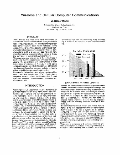
Triple wireless voice data transmission system designStudent :,Instructor :, UniversityEvery day, in our work and in our leisure time, we come in contact with and use a variety of modern communication media, the most common being the telephone, radio, television, and the Internet. Though these media we are able to communicate (nearly) instantaneously with people on diffident continents, transact our daily business, and receive information about various developments and events of note that occur all around the world. Electronic mail and facsimile transmission have made it possible to rapidly communicate written message across great distances.Wireless communications. The development of wireless communications stems from the works of Oersted, Faraday, Gauss, Maxwell, and Hertz. In1820, Oersted demonstrated that an electric current produces a magnetic field. On August 29,1831,Michael Faraday showed that an induced current is produced by moving a magnet in the vicinity of a conductor. Thus, he demonstrated that a changing magnetic field produces an electric field. With this early work as background, James C. Maxwell in 1864 predicted the existence of electromagnetic radiation and formulated the basic theory that has been in use for over a century. Maxwell’s theory was verified experimentally by Hertz in 1887.In 1894, a sensitive device that could device that could detect radio signals, called the coherer, was used by its inventor Oliver Lodge to demonstrate wireless communication over a distance of 150 yards at Oxford, England. Guglielmo Marconi is credited with the development of wireless telegraphy. Marconi demonstrated the transmission of radio signals at a distance of approximately 2 kilometers in 1895. Two years later, in 1897 , he patented a radio telegraph system and established the Wireless Telegraph and Signal Company. On December 12, 1901, Marconi received a radio signal at Signal Hill in Newfoundland, which was transmitted from Cornwall, England, a distance of about 1700 miles.The invention of the vacuum tube was especially instrumental in the development of radio communication system .The vacuum diode was invented by Fleming in 1904 and the vacuum triode amplifier was invented by De Forest in 1906, as previously indicated. The invention of the triode made radio broadcast possible in the early part of the twentieth century. Amplitude modulation (AM) broadcast was initiated in 1920 when radio station KDKA, Pittsburgh, went on the air. From that date, AM radio broadcasting grew rapidly across the country and around the world. The super heterodyne AM radio receiver, as we know it today, was invented by Edwin Armstrong during World War I. Another significant development in radio communications was the invention of Frequency modulation (FM), also by Armstrong.In 1933, Armstrong built and demonstrated the first FM communication system. However, the use of FM was slow to develop compared with AM broadcast. It was not until the end of World War II that FM broadcast gained in popularity and developed commercially.The first television system was built in the United States by V. K. Zworykin and demonstrated in 1929. Commercial television broadcasting began in London in 1936 by the British Broadcasting Corporation(BBC) . Five years later the Federal Communications Commission(FCC) authorized television broadcasting in the United States.ELEMENTS OF AN ELECTRICAL COMMUNICA SYSTEM Electrical communication systems are designed to send messages or information from a source that generates the message to one more destinations. In general, a communication system can be represented by the functional block diagram shown . The information generated by the source may be of the form of voice (speech source), a picture (image source), or plain text in some particular language, such as English , Japanese, German , French, etc. An essential feature of any source that generates information is that its output is described in probabilistic terms; i.e., the output of a source is not deterministic. Otherwise, there would be no need to transmit the message.A transducer is usually required to convert the output of a source into an electrical signal that is suitable for transmission. For example, a microphone serves as the transducer that converts an acoustic speech signal. At the destination, a similar transducer is required to convert the electrical signals that are received into a form that is suitable for the user; e.g., acoustic signals, images, etc.The heart of the communication system consists of three basic parts, namely, the transmitter, the channel, and the receiver. The functions performed by these three elements are described next.The Transmitter. The Transmitter converts the electrical signal into a form that is suitable for transmission though the physical channel or transmission medium. For example, in radio and TV broadcast, the Federal Communications Commission (FCC) specifies the frequency range for each transmitting station. Hence, the transmitter must translate the information signal to be transmitted into the appropriate The Transmitter range that matches the frequency allocation assigned to the transmitter. Thus, signal transmitted by multiple radio station do not interfere with one another. Similar functions are performed in telephone communication systems where the electrical speech signals from many users are transmitted over the same wire.In general, the transmitter performs the matching of the message signal to the channel by a process called modulation. Usually, modulation involves the use of the information signal to systematically vary either the amplitude, frequency, or phase of a sinusoidal carrier. For example, in AM radio broadcast, the information signal that is transmitted is contained in the amplitude variations of the sinusoidal carrier, which is the center frequency in the amplitude modulation. In FM radio broadcast., the information signal that is transmitted is contained in the frequency variations of thesinusoidal carrier. This is an example of frequency modulation. Phase modulation (PM) is yet a third method for impressing the information signal on a sinusoidal carrier.In general, carrier modulation such as AM, FM, and PM is performed at the transmitter, as indicated above, to convert the information signal to a form that matches the characteristics of the channel. Thus, though the process of modulation, the choice of the type of modulated in frequency to match the allocation of the channel. The choice of the type of modulation is based on several factors, such as the amount of bandwidth over the channel, the type of noise and the interference that the signal encounters in transmission. In any case, the modulation process makes it possible to accommodate the transmission of multiple messages from many users over the same physical channel.In addition to modulation, other functions that are usually performed at the transmitter are filtering of the information-bearing signal , amplification of the modulated signal, and in case of wireless transmission, radiation of the signal by means of a transmitting antenna.The channel. The communications channel is the physical medium that is used to send the signal from the transmitter to the receiver. In wireless transmission, the channel is usually the atmosphere (free space). On the other hand, telephone channels usually employ a variety of physical media, including wirelines, optical fiber cables, and wireless (microwave radio). Whatever the physical medium for signal transmission, the essential feature is that the transmitted signal is corrupted in a random manner by a variety of possible mechanisms. The most common from of signal degradation comes in the form of additive noise ,which is generated at the front end of the receiver, where signal amplification is performed. This noise is often called thermal noise. In wire less transmission, additional additive disturbances are man-made noise, and atmospheric noise picked up by a receiving antenna. Automovile ignition noise is an example of man-made noise, and electrical lightning discharges from thunderstorms is an example of atmospheric noise. Interference from other users of the channel is another form of additive noise that often arises in both wireless and wire line communication systems .In some radio communication channels, such as the ionospheric channel that is used for long range ,short-wave radio transmission, another form of signal degradation is multipath propagation. Such signal distortion is characterized as a nonadditive signal disturbance which manifests itself as time variations in the signal amplitude, usually called fading .Both additive and nonadditive signal distortions are usually characterized as random phenomena and described in statistical terms. The effect of these signal distortions must be taken into account on the design of the communication system.In the design of a communication system, the system, the system designer works with mathematical models that statistically characterize he signal distortion encountered on physical channels. Often, the statistical description that is used in mathematical model is a result of actual empirical measurements obtained from experiments involving signal transmission over such channels .In such cases , there isa physical justification for the mathematical model used in the design of communication systems. On the other hand, in some communication system designs ,the statistical characteristics of the channel may vary significantly with time. In such cases, the system design may designer may design a communication system that is robust to the variety of signal distortions. This can be accomplished by having the system adapt some of its parameters to the channel distortion encountered.The receiver. The function of the receiver is to recover the message signal contained in the received signal. If the message signal is transmitted by carrier modulation, the receiver performs carrier demodulation in order to extract the message from the sinusoidal carrier. Since the signal demodulation is performed in the presence of additive noise and possibly other signal distortion, the demodulated message signal is generally degraded to some extent by the presence of these distortions in the received signal. As we shall see, the fidelity of the additive noise, the type and strength of any other additive interference, and the type of any nonadditive interference.Besides performing the primary function of signal demodulation, the receiver also performs a number of peripheral functions, including signal filtering and noise suppression.Digital Communication SystemAn electrical communication system in rather broad terms based on the implicit assumption that message signal is a continuous timevarying waveform. We refer to such continuous-time signal waveforms as analog sources. Analog signal can be transmitted directly via modulation over the communication channel and demodulated accordingly at the receiver. We call such a i communication system an analog communication system.Alternatively, an analog source output may be converted into a digital form and the message can be transmitted via digital modulation as a digital signal at the receiver. There are some potential advantage to transmitting an analog signal by means of digital modulation. The most important reason is that signal fidelity is better controlled though digital transmission than analog transmission. In particular, digital transmission allows us to regenerate the digital signal in long-distance transmission, thus eliminating effects of noise at each regeneration point. In contrast, the noise added in analog transmission is amplified along with the signal when amplifiers are used periodically to boost the signal level in long-distance transmission. Another reason for choosing digital transmission over analog is that the analog message signal may be highly redundant. With digital processing, redundancy may be removed prior to modulation, thus conserving channel bandwidth. Yet a third reason may be that digital communication systems are often cheaper to implement.In some applications, the information to be transmitted is inherently digital; e.g., in the form of English text, computer data, etc. In such cases, the information source that generates the data is called a discrete (digital)source.In a digital communication systems , the some applications, the functional operations performed at the transmitter and receiver must be expanded to includemessage signal discrimination at the transmitter and message signal synthesis or interpolation at the receiver. Additional functions include redundancy removal, and channel coding and decoding.The source output may be either an analog signal, such as audio or video signal, or a digital signal , such as the output of a computer which is discrete in time and has a finite number of output characters. In a digital communication system, the message produced by the source are usually converted into a sequence of binary digits as possible. In other words, we seek inefficient representation of the source output of either an analog or a digital source into a sequence of binary digits is called source encoding or date compression.The sequence of binary digits from the coerce encoder, which we call the information sequence is passed to the channel encoder. The purpose of the channel encoder is to introduce, in a controlled manner, some redundancy in binary information sequence which can be used at the receiver to overcome the effects of noise and interference encountered in the transmission of the signal though the channel. Thus the added redundancy serves to increase the reliability of the received data and improves the fidelity in decoding the deceived signal. In fact, redundancy serves in the information sequence aids the receiver in decoding the desired information sequence .The binary sequence at the output of the channel encoder is passed to the digital modulator, which servers as the interface to the communications channel. Since nearly all of the communication channels encountered in practice are capable of transmitting electrical signals (waveforms), the primary purpose of the digital modulator is to map the binary information sequence into signal waveforms.At the receiving end of a digital communication system, the digital demodulator processes the channel-corrupted transmitted waveform and reduces reduce each waveform to a signal number that represents an estimate of the transmitted data symbol (binary or Mary) . When there is no redundancy in the transmitted information, the demodulator must decide which of the M waveform was transmitted in any given time interval. A measure of how well the demodulator and encoder perform is the frequency with which errors occur in the decoded sequence.As a final step, when an analog output is desired, the source decoder accepts the output sequence from the channel and , from knowledge of the source-encoding method used, attempts to reconstruct the original signal from the source.双工无线语音数据传输系统的设计学生:学院指导老师:汉大学在日常的工作和生活中,人们每天都要接触和使用大量的现代通信系统和通信媒介,其中最常见的是电话,无线电广播,电视和因特网。


信道估计的书-回复
在通信领域中,信道估计是一个关键课题,对于理解和优化无线通信系统的性能至关重要。
以下是一些关于信道估计的参考书籍:
1. 《无线通信中的信道估计》:作者周炯槃、庞沁华等编著,该书详细介绍了无线通信系统中的信道模型以及相应的信道估计理论和方法。
2. 《MIMO-OFDM无线通信系统中的信道估计技术》:作者王文博,这本书主要聚焦于多输入多输出(MIMO)与正交频分复用(OFDM)技术结合的无线通信系统中的信道估计问题。
3. 《无线通信信道估计算法及应用》:作者胡庆洪、张平,该书对各种无线通信信道估计算法进行了深入的探讨,并结合实际应用进行解析。
4. "Wireless Communications: Principles and Practice"(《无线通信:原理与实践》):作者Theodore S. Rappaport,此书为英文原版教材,其中包含了详细的无线通信基础理论以及信道建模与估计的内容。
以上书籍适合于通信工程、电子信息等相关专业的学生和研究人员阅读学习。
DATA SHEET WAVE 3000WAVE 3000CONNECT WITHOUT LIMITSWAVE WORK GROUP COMMUNICATIONSWAVE 3000 is part of the WAVE Work GroupCommunications portfolio - a range of solutions delivering instant and secure PTT communications across your entire organization. From nationwide networks to small communities and businesses, the WAVE solutions keep information flowing quickly and securely between workers, managers and support teams.WAVE solutions let you build interoperable, highlyextensible and flexible PTT communications networks that connect and extend your proven and trusted Motorola two-way radio systems to broadband networks and devices, anywhere.WAVE 3000WAVE 3000 is a simple, easily installed solution designed for small to medium businesses. It allows management and supervisors to stay in touch with workers using their smartphone or tablet. Radio PTT functionality is delivered through an application that connects securely through a dedicated WAVE 3000 server.GREATER REACH For the business owner who is travelling, or the managerwho is working from home, WAVE 3000 delivers the two-way radio experience over any broadband IP network:Wi-Fi, 3G or 4G cellular. You can communicate with yourworkers from wherever you are.MORE CHOICE For the office executive, WAVE 3000 gives you theopportunity to integrate all communications onto a single device. There’s no need to carry a smartphone and a radio into your meetings.OPTIMAL FLEXIBILITYFor the CIO, WAVE 3000 gives you the flexibility to be efficient. You can activate or deactivate any user in any facility at any time, direct from your desktop. Whether you’re connecting visitors, enabling contractor communications, or facilitating a one-time collaboration, WAVE 3000 delivers performance and flexibility.WAVE 3000 is highly scalable, and can grow as yourbusiness grows. The server supports up to 500 smartphone users, but additional user licenses can be purchased whenever needed.Whether it’s an extension of your MOTOTRBO Connect Plus two-way radio system, or a standalone broadband PTT network, Motorola’s WAVE 3000 solution empowers you to connect without limits.WAVE 3000 delivers instant and secure broadband push-to-talk (PTT) communications for small to mediumbusinesses. Whether you’re communicating with MOTOTRBO ™ radio users or with other smartphone users, WAVE3000 makes itsimple and affordable.LOCATION MAPPING FOR CONTACTSThe map screen on your WAVE Mobile Communicator shows at a glance the location of other WAVE users, allowing you to optimize your operations.CALL HISTORYThe WAVE Mobile Communicator keeps a record of all the calls you’ve made since your last logon.PRESENCE INDICATION FOR CONTACTSSee immediately who’s online and available. The WAVE Mobile Communicator shows status information for all your contacts.ACTIVITY INDICATIONEven if you can’t listen to every call, the WAVE Mobile Communicator will show you when a talkgroup is active, and which user is speaking.OPERATES OVER ANY IP NETWORKThe WAVE Mobile Communicator can use any wireless IP network – whether that’s cellular 3G or 4G, domestic or international, or Wi-Fi, private or public.SECURE COMMUNICATIONSYou can be confident in the confidentiality of your communications. The WAVE Mobile Communicator secures control and voice traffic using AES 256 bit encryption.ANDROID AND IOS SUPPORTWAVE Mobile Communicator can be used on any smartphone or tablet using the Apple iOS or Google Android operating system. Download it for free from the Apps stores.Text with other WAVE users when PTT communication is difficult such as in noisy environments.GROUP TEXTUNIQUE USER PROFILELog in to your WAVE Mobile Communicator and your unique user profile of contacts and talkgroups are loaded automatically, so you can be productive right away.PRIVATE, GROUP, MULTI-GROUP CALLSMake discreet private calls or connect with a whole team, group or department. The WAVE Mobile Communicator can communicate with talkgroups of thousands of people at once. You can listen to up to 16 talkgroups simultaneously.TheWAVE Mobile Communicator turns your Apple orAndroid smartphone or tablet into a secure, multi-channel PTT communications handset. Users can participate in group PTT communications with users on two-way radio systems or other smart devices, or have a private PTT call with a specific individual. Mapping, presence and channel activity monitoring improve situational awareness for everyone.WAVE MOBILE COMMUNICATORThe WAVE 3000 Server is the self-contained appliance at the heart of the WAVE 3000 solution. It’s a high capacity voice and data gateway that manages communications between smartphones and interfaces to the MOTOTRBO Connect Plus system. It supports up to 500 smartphone users, with up to 60 concurrent calls.Configuration is done through a central user interface that can be securely accessed from remote locations.The WAVE 3000 Server gives you robust and secure management of your client accounts. The Provisioning Portal has password protection, and is accessible remotely using an SSL-based secure mechanism.SECURE CENTRALIZED PROVISIONINGWAVE 3000 SERVERWAVE 3000 SERVER SPECIFICATIONS:Dimensions (W x D x H) 36” L x 23”W x 10”H (91.4cm x 58.4cm x 25.4cm)Weight (fully equipped) 56 lbs (25.5 Kg)Operating Environment 0°C to +50°C, 0 to 95% RH, non-condensing Input Power 90-264 Vac, 500 WAt the heart of your system, the WAVE 3000 server provides a convenient central point for adding new features and functionality as your business grows and evolves. The upgrade procedure is quick and simple.SIMPLE UPGRADESThe WAVE 3000 Server ships with built-in utilities that allow you to diagnose and resolve issues in your network configuration.BUILT-IN DIAGNOSTICSTo better control confidentiality, efficiency and talkpath usage, you can control which of your smartphone users have access to private call functionality.CONTROL OF PRIVATE CALL USAGEFrom the web-based Provisioning Portal, you can manage all aspects of your user accounts, from adding a user to deactivating a user, creating or managing a talkgroup, and provisioning private call contacts for each user.FLEXIBLE CLIENT MANAGEMENTCall logs are maintained on the WAVE 3000 server for 7 days, and you can export the log to a file (csv format) for long-term traceability and accountability.CALL LOGGINGEach WAVE 3000 Server supports up to 500 users,and uses talkpaths efficiently to get the most from your system.SCALABLE CAPACITYFor more information on WAVE 3000, go to /WAVEFor more information on WAVE Workgroup Communication solutions, go to /WAVEMOTOROLA, MOTO, MOTOROLA SOLUTIONS and the Stylized M Logo are trademarks or registered trademarks of Motorola Trademark Holdings, LLC and are used under license. All other trademarks are the property of their respective owners. © 2015 Motorola Solutions, Inc. All rights reserved. R3-4-50102015-07WAVE 3000 is designed to integrate with a MOTOTRBO Connect Plus, Capacity Plus and Linked Capacity Plus radio using a wireline interface. It can also be used as a standalone broadband PTT solution where radios are not required. The WAVE 3000 Server manages all communications between MOTOTRBO systems and broadband networks and devices, and maintains user credentials and configuration information for smartphone clients.For MOTOTRBO Connect Plus systems, the WAVE 3000 Server integrates directly with an XRT 9000 or XRT 9100 Connect Plus Gateway. This interface provides an IP-based wireline connection to your Connect Plus system for a highly-scalable, reliable and secure broadband PTT integration.WAVE 3000 can also be deployed as a broadband-only PTT solution where integration with a MOTOTRBO radio system is not required. In this instance the WAVE 3000 Server provides multi-channel broadband PTT connectivity over any 3G/4G LTE/Wi-Fi data network.EXTENDING A MOTOTRBO CONNECT PLUS SYSTEMWAVE 3000 AS A STANDALONE BROADBAND PTT SYSTEMFor MOTOTRBO Capacity Plus systems there is no requirement for an XRT gateway or donor radios as the WAVE 3000 Server integrates directly with the EXTENDING A MOTOTRBO CAPACITY PLUS SYSTEMFor MOTOTRBO Linked Capacity Plus systems, the WAVE 3000 Server also integrates directly using the MNIS voice interface. No XRT or donor radios are EXTENDING A MOTOTRBO LINKED CAPACITY PLUS SYSTEM。
Wireless Communications*byJoshua S. Gans, Stephen P。
King and Julian Wright1。
IntroductionIn 1895, Guglielmo Marconi opened the way for modern wireless communications by transmitting the three—dot Morse code for the letter ‘S' over a distance of th ree kilometers using electromagnetic waves。
From this beginning,wireless communications has developed into a key element of modern society. From satellite transmission, radio and television broadcasting to the now ubiquitous mobile telephone,wireless communications has revolutionized the way societies function.This chapter surveys the economics literature on wireless communications。
Wireless communications and the economic goods and services that utilise it have some special characteristics that have motivated specialised studies. First,wireless communications relies on a scarce resource –namely,radio spectrum –the property rights for which were traditionally vested with the state。
IEEE TRANSACTIONS ON COMMUNICATIONS,VOL.57,NO.10,OCTOBER20092977 Differential Modulation for Two-Way Wireless Communications:A Perspective of Differential Network Coding at the Physical LayerTao Cui,Feifei Gao,Member,IEEE,and Chintha Tellambura,Senior Member,IEEEAbstract—This work considers two-way relay channels (TWRC),where two terminals transmit simultaneously to each other with the help of a relay node.For single antenna sys-tems,we propose several new transmission schemes for both amplify-and-forward(AF)protocol and decode-and-forward(DF) protocol where the channel state information is not required. These new schemes are the counterpart of the traditional non-coherent detection or differential detection in point-to-point communications.Differential modulation design for TWRC is challenging because the received signal is a mixture of the signals from both source terminals.We derive maximum likelihood (ML)detectors for both AF and DF protocols,where the latter can be considered as performing differential network coding at the physical layer.As the exact ML detector is prohibitively complex,we propose several suboptimal alternatives including decision feedback detectors and prediction-based detectors.All these strategies work well as evidenced by the simulation results. The proposed protocols are especially useful when the required average data rate is high.In addition,we extend the protocols to the multiple-antenna case and provide the design criterion of the differential unitary space time modulation(DUSTM)for TWRC.Index Terms—Differential modulation,physical layer network coding,two-way relay networks.I.I NTRODUCTIONT WO-W AY communication is a popular type of modern communications,where two source terminals simultane-ously communicate.Recently,relay-aided two-way transmis-sions have attracted a great deal of research interest[1]–[7]. For example,both AF(amplify-and-forward)and DF(decode-and-forward)relaying schemes under one-way relay channels were extended to the two-way relay channels(TWRC)in[1]. In[2],network coding from network layer[8]was extended Paper approved by E.Perrins,the Editor for Modulation Theory of the IEEE Communications Society.Manuscript received May22,2008;revised September4,2008.T.Cui is with the Department of Electrical Engineering,California Institute of Technology,Pasadena,CA91125,USA(e-mail:taocui@). F.Gao is with School of Engineering and Science,Jacobs University, Bremen,Germany.(e-mail:feifeigao@).C.Tellambura is with the Department of Electrical and Computer Engineering,University Alberta,Edmonton,Alberta T6G2C5(e-mail: chintha@ece.ualberta.ca).This work has been supported in part by DARPA grant N66001-06-C-2020,Caltech’s Lee Center for Advanced Networking,the Okawa Foundation Research Grant and a gift from Microsoft Research,the Natural Sciences and Engineering Research Council of Canada,the Informatics Circle of Research Excellence,and the Alberta Ingenuity Fund.This paper has been presented in part at the IEEE Global Communications Conference,Dec.2008,New Orleans,LA,USA.Digital Object Identifier10.1109/TCOMM.2009.10.080254to physical layer,but unfortunately,was only effective in an additive white Gaussian noise(AWGN)environment.In[3], a decode and forward scheme was proposed which works for fading channels by using error detection codes at the relay. In[4],a new type of relaying scheme,called partial decode-and-forward was designed for TWRC with fading,and the space-time codes that can achieve full spatial diversity were also proposed in the same paper.In[5],[6],the relay function was optimized to attain the minimum error probability at both source terminals,and a new relaying scheme,called estimate-and-forward(EF),was developed.The capacity region of TWRC is analyzed in[7].Most works on TWRC[1],[4]–[6]are based on the assumption of knowledge of channel state information(CSI),which for example can be obtained from the method developed in[9],and the corresponding data recovery relies on coherent detection.In practice,accurate CSI is hard to obtain in a rapidly changing mobile environment or when multiple transmit an-tennas are employed,especially in TWRC where two channel coefficients are required to be estimated each way.In these cases,non-coherent schemes,which do not rely on instant CSI, become a preferred choice[10]–[12].The earliest such scheme is the so-called differential phase-shift keying(DPSK),which has long been used in single-antenna links.The receiver in this case decodes the information by comparing the phase of the current symbol to that of the previous symbol.This differential scheme was extended to the multiple-antenna scenario in[11], which uses matrix signal group modulations.The resulting scheme is called differential unitary space time modulation (DUSTM).However,the development of such a differential strategy for TWRC is a new and challenging problem as the received signal at one terminal is a mixture of its transmitted signal and the signal from the other terminal.If the self-signal component is known,it can be subtracted from the received signal,and the conventional differential scheme[10]–[12]can then be applied on the residual signal.However,when both channels are unknown,the mixture of the two unknown parts destroys the phase rotation property and prevents the use of the traditional differential scheme.In this work,wefirst consider the AF relaying protocol and derive the probability density function(pdf)of the received signal for a single antenna system.Since the pdf cannot be expressed in a simple form,we propose a suboptimal criterion,where the pdf of the received signal conditioned0090-6778/09$25.00c⃝2009IEEE2978IEEE TRANSACTIONS ON COMMUNICATIONS,VOL.57,NO.10,OCTOBER 2009on the desired information can be exhibited by the modi fied bessel function.As the maximum likelihood (ML)detector may suffer from high complexity and other implementation issues,we propose a decision feedback scheme that uses three consecutive received signals.Moreover,a prediction-based detector is proposed for the AF protocol over time varying channels.In the conventional DF protocol,the relay first de-codes the signals from the two source terminals and re-encodes the information before broadcasting.In this case,the signal from the first terminal,denoted by s 1,and the signal from the second terminal,denoted by s 2,are detected separately.In contrast,we propose to directly detect s 1+s 2and re-encode s 1+s 2according to a sophisticatedly designed code book.The new strategy in fact performs no-coherent network coding at the physical layer and is named physical layer differential network coding (PLDNC).Finally,all the proposed schemes are extended to the multiple antennas environment.The design criterion of DUSTM that is applicable to PLDNC is also given through the performance analysis of the pairwise error probability.The simulations show that the proposed strategies are especially useful when the required average data rate is high.Notations :Vectors and matrices are boldface small and capital letters,respectively;the transpose,complex conjugate,Hermitian,Frobenius norm and inverse of the matrix A are denoted by A T ,A ∗,A H ,∥A ∥F and A −1,respectively;∥a ∥2is the l 2norm of a ;diag {a }denotes a diagonal matrix with thediagonal element constructed from a ;I T is the T ×T identity matrix;E {⋅}denotes the statistical expectation.j =√−1is the imaginary unit.II.D IFFERENTIAL M ODULATION IN S INGLE A NTENNAS YSTEMSA.System ModelConsider a network with two source nodes T i ,i =1,2and one relay node ℝ,where T i ’s exchange information with the help of ℝ.The half-duplex system is assumed throughout this paper,i.e.,each node cannot transmit and receive at the same time.Nonetheless,the results in this paper can be readily generalized to the full duplex systems.The system is operated in time slots.In [4],the 2-,3-,4-time slot protocols are proposed.By the “2-time slot protocol",we mean that one time slot is divided into 2phases and both phases will be indexed by n for the n -th time slot.Similar de finitions hold for the 3-and 4-time slot protocols.For the 4-time slot protocols,the communication between T i ’s actually applies the one-way relay channel twice,and the differential modulation in [13]can be directly used.Moreover,the conventional differential modulation can also be used for the 3-time slot protocols,as shown in [14].This work mainly focuses on the 2-time slot protocol,where the first phase is used for uplink transmission from T i ’s to ℝand the second phase is used for downlink transmission from ℝto T i ’s.Note that T i ’s are active simultaneously in the first phase,which can provide a higher spectral ef ficiency [4]than 3-and 4-time slot protocols.Suppose T i wishes to transmit s i [n ]∈Q in time slot n ,where Q is the signal constellation.Similar to the conven-tional DPSK modulation,the M -PSK constellation is used,i.e.,Q ={e jθ∣θ=2πM l,l =0,1,...,M −1}.Suppose that the trans-mitted signals by T i and ℝat time slot n are x i [n ]and x r [n ],respectively.The transmitted signal is modulated as x i [n ]=x i [n −1]s i [n ].The received signals at ℝand T i arey r [n ]=ℎ1x 1[n ]+ℎ2x 2[n ]+w r [n ],y i [n ]=ℎi x r [n ]+w i [n ],(1)respectively,where ℎi is the channel gain between T i and ℝ;w r [n ]and w i [n ]are zero-mean AWGNs at ℝand T i withvariances σ2r and σ2s ,respectively.In (1),a reciprocal channel is assumed for notational simplicity,and ℎi remains static over at least two time slots,unless otherwise stated.The protocols proposed in this paper can also be applied to the case without reciprocal channel.To realize differential modulation,we do not assume the availability of knowledge of ℎ1and ℎ2at any node.However,the statistics of ℎi ’s are assumed known,which is fixed as CN (0,1)in this paper.The differential schemes under the two protocols,AF and DF,are proposed in the following subsections.B.Amplify-and-ForwardWith the AF protocol,the transmit signal from ℝis a linear transformation of its received signal,i.e.,x r [n ]=βy r [n ]where β>0is a constant to keep the average power constraint at ℝ.The received signal at T i isy i [n ]=βℎi (ℎ1x 1[n ]+ℎ2x 2[n ])+βℎi w r [n ]+w i [n ].(2)Exploiting symmetry,we focus only on T 1,and T 2can be treated similarly.The signal (2)at T 1can be written asy 1[n ]=βℎ1ℎ2x 2[n ]+βℎ21x 1[n ]+z 1[n ],(3)where z 1[n ]is zero-mean AWGN with variance σ2z =β2∣ℎ1∣2σ2r +σ2s conditioned on a deterministic ℎ1.When ℎ21is known at T 1,the contribution of x 1[n ]on y 1[n ]can be eliminated as T 1knows the signal it has sent.In this case,conventional differential modulation follows naturally on the remaining signal,which resembles the differential modulation in conventional one-way communication.However,the prob-lem becomes complicated when ℎ21is unknown at T 1since βℎ21x 1[n ]can no longer be canceled,even though x 1[n ]is known.Due to the mixture of the two signal components,the conventional differential detection fails here.1)Optimal ML Detector:We first consider the optimal ML detector,which should be derived from the pdf of y 1[n ],y 1[n −1]conditioned on s 1[n ],s 2[n ].Here,we slightly modify thesystem model by requiring ℝto transmit βy ∗r[n ],the conjugate version of βy r [n ].De fine y 1=[y 1[n ],y 1[n −1]]T ,which can be written in matrix form asy 1=βℎ1ℎ∗2X H 21+β∣ℎ1∣2x ∗1+z 1,(4)where 1=[1,1]T ,x 1=[x 1[n −1],x 1[n ]]T ,x 2=[x 2[n −1],x 2[n ]]T ,X 2=diag {x 2}and z 1=[z 1[n −1],z 1[n ]]T .Clearly,y 1is complex Gaussian given ℎ1and x 1,x 2;i.e.1,p (y 1∣ℎ1,x 1,x 2)=1(2π)2det(C )exp (−(y 1−β∣ℎ1∣2x ∗1)H C −1(y 1−β∣ℎ1∣2x ∗1)),(5)1Thisexpression is only valid for reciprocal channels.When the channelis not reciprocal,∣ℎ1∣2should be replaced with ℎ(1)1ℎ∗(2)1,where ℎ(1)1and ℎ(2)1are uplink and downlink channels,respectively.CUI et al.:DIFFERENTIAL MODULATION FOR TWO-WAY WIRELESS COMMUNICATIONS:A PERSPECTIVE OF DIFFERENTIAL NETWORK CODING (2979)p (y 1∣ℎ1,x 1,x 2)=1(2π)2((β2t (1+σ2r )+σ2s )2−(β2t )2)exp (−(∣y 1[n −1]−βtx ∗1[n −1]∣2+∣y 1[n ]−βtx ∗1[n ]∣2)(β2t (1+σ2r )+σ2s)(β2t (1+σ2r )+σ2s )2−(β2t )2+β2t (y 1[n −1]−βtx ∗1[n −1])s 2[n ](y ∗1[n ]−βtx 1[n ])(β2t (1+σ2r )+σ2s)2−(β2t )2+β2t (y ∗1[n −1]−βtx 1[n −1])s ∗2[n ](y 1[n ]−βtx ∗1[n ])(β2t (1+σ2r )+σ2s)2−(β2t )2),(7)p (y 1∣x 1,x 2)≈12π2β4(2σ2r +σ4r)exp(Bβ(2σ2r +σ4r))√(C +2σ2r +σ4r)β2AK −1(2√(C2σ2r +σ4r+1)Aβ2(2σ2r +σ4r)),(8)p (u 1[n ]∣s 2[n ],s 1[n ])=1πβ2(∣s2[n ]−s 1[n ]∣2+2σ2r )exp (2σ2sβ2(∣s 2[n ]−s 1[n ]∣2+2σ2r ))K 0(2√∣u 1[n ]∣2β2(∣s2[n ]−s 1[n ]∣2+2σ2r )),(12)whereC =β2∣ℎ1∣2X H 2[1111]X 2+(β2∣ℎ1∣2σ2r +σ2s )I 2.(6)The pdf can be further expanded as (7)at the top of this pagewhere t ≜∣ℎ1∣2.To obtain the optimal ML detector,we need to derive p (y 1∣x 1,x 2)by integrating p (y 1∣ℎ1,x 1,x 2)over t .Note that the integral of (7)actually depends only on s 2[n ].Hence,only a single variable search is needed.Thus,the complexity of the search is greatly reduced.Unfortunately,obtaining a closed-form solution of p (y 1∣x 1,x 2)appears intractable,and numerical integration must be used.We therefore consider the case when σ2s →0,in which case p (y 1∣x 1,x 2)can be approximated by (8)at the top of this page [14],where K −1(⋅)is the −1th order modi fied Bessel function of the second kind,andA =(1+σ2r )(∣y 1[n −1]∣2+∣y 1[n ]∣2)−y 1[n −1]s 2[n ]y ∗1[n ]−y ∗1[n −1]s ∗2[n ]y 1[n ],B =(1+σ2r )(y 1[n −1]x 1[n −1]+y ∗1[n −1]x ∗1[n −1]+y 1[n ]x 1[n ]+y ∗1[n ]x ∗1[n ])−y 1[n −1]s 2[n ]x 1[n ]−y ∗1[n ]s 2[n ]x ∗1[n −1]−y ∗1[n −1]s ∗2[n ]x ∗1[n ]−y 1[n ]s ∗2[n ]x 1[n −1],C =2(1+σ2r )−x ∗1[n −1]s 2[n ]x 1[n ]−x 1[n −1]s ∗2[n ]x ∗1[n ].(9)The approximate ML detector is thus obtained by maximizing (8).2)Suboptimal ML Detector:Since the closed-form optimal ML detector is not available,we consider a heuristic and suboptimal ML detector.Assuming x i [n ]=x i [n −1]s i [n ],the contribution of x 1[n ]on y 1[n ]can be eliminated asu 1[n ]=y 1[n ]−y 1[n −1]s 1[n ]=βℎ1ℎ2x 2[n −1](s 2[n ]−s 1[n ])+z 1[n ]−s 1[n ]z 1[n −1].(10)Given ℎ1and s 2[n ]−s 1[n ],u 1[n ]is complex Gaussian withpdfp (u 1[n ]∣ℎ1,s 2[n ],s 1[n ])=12π(β2∣ℎ1∣2∣s 2[n ]−s 1[n ]∣2+2β2∣ℎ1∣2σ2r +2σ2s)×exp (−∣u 1[n ]∣2β2∣ℎ1∣2∣s 2[n ]−s 1[n ]∣2+2β2∣ℎ1∣2σ2r +2σ2s).(11)Integrating (11)over the pdf of ℎ1,we obtainp (u 1[n ]∣s 2[n ],s 1[n ])(12)at the top of this page,where equality comes from [15,3.471],and K 0(⋅)is the zeroth order modi fied Bessel function of the second kind.The suboptimal ML detector can then be obtained asˆs 2[n ]=argmax s 2[n ]p (u 1[n ]∣s 2[n ],s 1[n ]).(13)This detector has the following interpretation.In the noise-free case,it is easily seen that ∣u 1[n ]∣2β2∣s 2[n ]−s 1[n ]∣2=∣ℎ1ℎ2∣2.Therefore,the solution of (13)should make β2∣s 2[n ]−s 1[n ]∣2close to ∣u 1[n ]∣2.From (13),if β2∣s 2[n ]−s 1[n ]∣2≪∣u 1[n ]∣2,s 2[n ]is unlikely to be the optimal solution as K 0(x )is a decreasing function.On the other hand,when β2∣s 2[n ]−s 1[n ]∣2≫∣u 1[n ]∣2,1πβ2(∣s 2[n ]−s 1[n ]∣2+2σ2r)penalizes this choice.Therefore,the ML detector forces β2∣s 2[n ]−s 1[n ]∣2to stay around ∣u 1[n ]∣2.However,the suboptimaldetector requires ∣s 2[n ]−s 1[n ]∣2=∣s ′2[n ]−s 1[n ]∣2,∀s 1[n ]∈Qand s 2[n ]=s ′2[n ],∀s 2[n ],s ′2[n ]∈Q .Clearly,BPSK satis fies this condition.For general M -PSK,the constellation for s 2[n ]can be rotated to satisfy this condition.3)Decision Feedback Detector:Eq.(13)uses only two received signals.By computing u 1[n ],...,u 1[n −K ],we can derive the joint pdf of u 1[n ],...,u 1[n −K ]by following (12).If the already detected symbols s 2[n −1],...,s 2[n −K ]are substituted into the resulting equation,a decision feedback detector can be obtained.However,this detector requires the computation of K 0(⋅).By assuming error-free detection in the previous time slots,we constructd [n ]=x 2[n −2](s 2[n −1]−s 1[n −1])u 1[n ]−x 2[n −1](s 2[n ]−s 1[n ])u 1[n −1]=x 2[n −2](s 2[n −1]−s 1[n −1])(z 1[n ]−s 1[n ]z 1[n −1])−x 2[n −1](s 2[n ]−s 1[n ])(z 1[n −1]−s 1[n −1]z 1[n −2]),(14)that only contains noise.The pdf of d [n ]can be obtained asp (d [n ]∣s 1[n −1],s 1[n ],s 2[n −1],s 2[n ])=1πˆσ2exp (−∣d [n ]∣2ˆσ2),(15)whereˆσ2=(∣s 2[n −1]−s 1[n −1]∣2+∣s 2[n ]−s 1[n ]∣2+∣s 2[n ]s 2[n −1]−s 1[n ]s 1[n −1]∣2)σ2z .(16)The decision feedback detector is used to maximize the pdf(15)over s 2[n ].As σ2z depends on ∣ℎ1∣2,one way to remove such dependence is to integrate (15)over ℎ1.Another way is to simply replace ∣ℎ1∣2with E {∣ℎ1∣2}=1.Note that s 2[n ]also appears in ˆσ2.To reduce the complexity,we propose to minimize ∣d [n ]∣2directly since d [n ]should be zero in the noise-free environ-ment.This detector requires s 2[n ]−s 1[n ]=0,∀s 2[n ],s 1[n ]∈Q .Hence,the two source terminals should transmit with different constellations.For example,we could choose Q 1={−1,1}and Q 2={−j,j }for T 1and T 2,respectively.When M -PSK is used,Q 2can be a rotation of Q 1.2980IEEE TRANSACTIONS ON COMMUNICATIONS,VOL.57,NO.10,OCTOBER 2009E {∣w e ∣2}=E ⎧⎨⎩βℎ21[n ]x 1[n ]+w 1[n ]−K ∑k =1p n,k (βℎ21[n −k ]x 1[n −k ]+w 1[n −k ])k −1∏i =0s 1[n −i ] 2⎫⎬⎭.(18)p (y r ∣s [n ])=1(2π)2((2+σ2r )2−∣s [n ]∣2)exp (−(1+σ2r )∣y r [n ]∣2+(2+σ2r −∣s [n ]2∣)∣y r [n −1]∣2+∣y r [n ]−y r [n −1]s [n ]∣2(2+σ2r)2−∣s [n ]∣2).(26)To improve the performance and reduce the error propaga-tion due to incorrectly decoded symbols,(15)can be readilyextended to multiple symbol detection.Note that d [n ]depends on z 1[n ],z 1[n −1],z 1[n −2].Thus,d [n ],d [n −1],d [n −2]are correlated.For simplicity,we do not give the explicit form of the multiple symbol detector here.4)Prediction Based Detector:When channel gains ℎ1and ℎ2vary over time,the contribution of x 1[n ]cannot be completely canceled from (10).Moreover,p (y 1∣x 1,x 2)is dif ficult to compute in time-varying channels.Motivated by [10],where the use of the prediction-based decision feedback differential detection is proposed for the point-to-point communication,we develop a similar TWRC differential detector.To this end,instead of subtracting y 1[n −1]s 1[n ]from y 1[n ],we consider canceling the effect of x 1[n ]by using K previously received symbols;i.e.,u 1[n ]=y 1[n ]−K ∑k =1p n,k y 1[n −k ]k −1∏i =0s 1[n −i ].(17)We need to find p n,k to minimize the expected noise variance and estimation error w e given in (18)at the top of this page.Hence,p n,k can be determined from the Yule-Walker equations as [16]p n =(ˇC ℎ1+(σ2r +σ2s β2)I K)−1b ,(19)where ˇC ℎ1=[E {ℎ21[n −i ](ℎ21[n −j ])∗}]and b =[E {ℎ21[n ](ℎ21[n −1])∗},⋅⋅⋅,E {ℎ21[n ](ℎ21[n −K ])∗}]T.Withthis p n ,we can write u 1[n ]in (17)asu 1[n ]=w e +βℎ1[n ]ℎ2[n ]x 2[n ]−βK ∑k =1p n,k ℎ1[n −k ]ℎ2[n −k ]x 2[n −k ]k −1∏i =0s 1[n −i ].(20)Since the joint distribution of ℎ1[n ]ℎ2[n ],...,ℎ1[n −K ]ℎ2[n −K ]is unknown,we approximate u 1[n ]as a complex Gaussian random variable with zero mean and varianceσ2u 1(s 2[n ],...,s 2[n −K ])=E {∣u 1[n ]∣2}=β2ˇs H ˇC ℎˇs +β2(2+σ2r )+σ2s −b H (ˇCℎ1+(σ2r +σ2s β2)I K )−1b ,(21)where s =[1,s 1[n ]s ∗2[n ],...,∏K −1i =0s 1[n −i ]s ∗2[n −i ]]T and ˇC ℎ=[E {ℎ1[n −i ]ℎ∗1[n −j ]}E {ℎ2[n −i ]ℎ∗2[n −j ]}].The pdf of u 1[n ]conditioned on s 2[n ],...,s 2[n −K ]can be approximated byp (u 1[n ]∣s 2[n ],...,s 2[n −K ])=12πσ2u 1(s 2[n ],...,s 2[n −K ])exp (−∣u 1[n ]∣2σ2u 1(s 2[n ],...,s 2[n −K ])).(22)We assume that s 2[n −1]...,s 2[n −K ],which are denoted as ˆs 2[n −1]...,ˆs 2[n −K ],have been detected correctly.The detector for s 2[n ]is then obtained by maximizing p (u 1[n ]∣s 2[n ],ˆs 2[n −1],...,ˆs 2[n −K ]).This prediction-based detector can also be extended to mul-tiple symbol detection.Suppose that u 1[n −1],...,u 1[n −K ]are obtained similarly as u 1[n ]in (17).By assuming that u 1[n ],u 1[n −1],...,u 1[n −K ]are jointly Gaussian,it is easy to obtain the pdf p (u 1[n ],u 1[n −1],...,u 1[n −K ]∣s 2[n ],...,s 2[n −K ]),maximizing which gives a multiple symbol detector.C.Decode-and-Forward1)Single Symbol Detector:The DF protocol requires the relay to decode its received signal.From (1),the received signals at the relay from the n -th and n −1-th time slots can be combined asy r =ℎ1X 11+ℎ2X 21+w r ,(23)where y r =[y r [n −1],y r [n ]]T ,X i =diag {x i [n −1],x i [n ]},i =1,2,1=[1,1]T and w r =[w r [n −1],w r [n ]]T .Clearly,y r is complex Gaussian given x 1,x 2;i.e.,p (y r ∣x 1,x 2)=1π2det(C )exp (−y H r C −1y r ),(24)whereC =[2s ∗1[n ]+s ∗2[n ]s 1[n ]+s 2[n ]2]+σ2r I 2.(25)Let s [n ]=s 1[n ]+s 2[n ].We can rewrite (24)as (26)at the top of this page.As several s 1[n ]and s 2[n ]pairs may give the same value of s 1[n ]+s 2[n ],we should use the maxi-mum a posteriori (MAP)detector by maximizing p (s [n ]∣y r )=p (y r ∣s [n ])p (s [n ])p (y r ),and s [n ]at the relay can be obtained from ˆs [n ]=argmax s [n ]=s 1[n ]+s 2[n ],s 1[n ],s 2[n ]∈Qp (y r ∣s [n ])p (s [n ]).(27)After obtaining ˆs [n ]=ˆs 1[n ]+ˆs 2[n ]from (27),we do notrequire ℝto transmit a scaled version of ˆs [n ]as was the case in the conventional DF protocol.To assist the differential scheme,we will apply an idea similar to network coding [8].Recall that in the basic network coding,source T i transmits b i ∈{0,1}.The relay decodes b 1and b 2separately and broad-casts b r =(b 1+b 2)mod 2.As T i already knows b i ,it can decode the signal from (b r −b i )mod2.In the conventional network coding,ℝis required to detect b 1and b 2separately at the physical layer and to perform the network coding at the networking layer.To apply physical layer network coding,we first solveˆs [n ]=ˆs 1[n ]+ˆs 2[n ]from (27)by searching through different s 1[n ]+s 2[n ]=e j 2πM l 1+e j 2πM l 2,l 1,l 2∈{0,1,...,M −1}.We thenuse a mapping function ℳto map ˆs [n ]to s r [n ]=ℳ(ˆs [n ]).By differential modulation,the relay then broadcasts x r [n ]=x r [n −1]s r [n ],where we have assumed the average power constraint of the relay is 0.5and x r [0]=1for notational simplicity.As T i knows s i [n ],it can decode signals from the other terminal if it receives the correct s 1[n ]+s 2[n ].Therefore,the mapping function should satisfy the condition ℳ(s 1[n ]+s 2[n ])=ℳ(s 1[n ]+s ′2[n ])and ℳ(s 1[n ]+s 2[n ])=CUI et al.:DIFFERENTIAL MODULATION FOR TWO-WAY WIRELESS COMMUNICATIONS:A PERSPECTIVE OF DIFFERENTIAL NETWORK CODING (2981)Pr(y 1[n ],y 1[n −1]∣s 1[n ],s 2[n ])=14πσ2s∑˜s 1[n ],˜s 2[n ]P e ({s 1[n ],s 2[n ]}→{˜s 1[n ],˜s 2[n ]})exp (−∣y 1[n ]−y 1[n −1]˜s r [n ]∣22σ2s),(32)ℳ(s ′1[n ]+s 2[n ]),∀s 1[n ]=s ′1[n ],s 2[n ]=s ′2[n ].We then pro-vide the following lemma.Lemma 1:For any p 1,p 2,q 1,q 2∈{0,1,...,M −1},e j 2πM p 1+e j 2πM p 2=e j 2πM q 1+e j 2πM q 2holds if1)((p 1−p 2)mod M )=M 2and ((q 1−q 2)mod M )=M2or,2)(p 1mod M )=(q 1mod M )and (p 2mod M )=(q 2mod M )or,3)(p 1mod M )=(q 2mod M )and (p 1mod M )=(q 2mod M ).Proof:From the condition in the lemma,we have e j 2πM p 1+e j 2πM p 2 2= e j 2πM q 1+e j 2πM q 22which gives cos (2πM (p 1−p 2))=cos (2πM (q 1−q 2)),and (e j 2πM p 1+e j 2πM p 2)2=(e j 2πM q 1+e j 2πM q 2)2which givesej 2πM (p 1+p 2)(1+cos (2πM(p 1−p 2)))=e j 2πM (q 1+q 2)(1+cos (2πM(q 1−q 2))).(28)Therefore,e j 2πM p 1+e j 2πM p 2=e j 2πM q 1+e j 2πM q 2holds if 1+cos (2πM (p 1−p 2))=0and 1+cos (2πM (q 1−q 2))=0or e j 2πM (p 1+p 2)=e j 2πM (q 1+q 2),where the latter condition implies ((p 1+p 2)mod M )=((q 1+q 2)mod M ).Substituting it into the condition in the lemma,we obtain cos (p 1−p 1+p 22)=cos (q 1−p 1+p 22).The lemma then follows.□2)Mapping function ℳ():To find the mapping,we borrow some concepts from graph theory.We first con-struct a graph G as in [5],where each node corresponds to s 1[n ]+s 2[n ]and there exists an edge between s 1[n ]+s 2[n ]and s 1[n ]+s ′2[n ]and another edge between s 1[n ]+s 2[n ]and s ′1[n ]+s 2[n ],∀s 1[n ]=s ′1[n ],s 2[n ]=s ′2[n ].Then,the mapping ℳcorresponds to a coloring of graph G .We assume that M colors are used.When M is odd,there do not exist l 1and l 2such that ((l 1−l 2)mod M )=M 2.From Lemma 1,each node in G corresponds only to s 1[n ]+s 2[n ]and s 2[n ]+s 1[n ].Therefore,the degree of each node is 2M −1,and each node lies exactly in two cliques,where each clique contains M nodes.We can show that the graph can be colored greedily using M colors.We first pick an arbitrary node and assign a color to this node.Then,the remaining M −1colors are assigned to M −1nodes in the two cliques,respectively.Note that all the nodes in the first clique corresponds to s 1[n ]+s ′2[n ]while they corresponds to s ′1[n ]+s 2[n ]in the second clique.There is no edge between nodes in the first clique and nodes inthe second clique since s 1[n ]=s ′1[n ],s 2[n ]=s ′2[n ].The greedy coloring does not void the coloring condition.We then apply the same process to each node.We can obtain a valid coloring with M colors in the end.When M is even,all s 1[n ]and s 2[n ]such that (l 1−l 2)mod M =M 2corresponds to the same node,i.e.,s 1[n ]+s 2[n ].We color this node using a color out of the M colors and remove this node from G ,which gives a graph G ′.In G ′,each node belongs to two cliques of size M −1.From the same greedy coloring algorithm as when Mis odd,G ′can be colored with M −1colors.Finally,M colorsare suf ficiently to color G .Therefore,we can obtain a valid mapping ℳfor any M .For example,when Q ={−1,1},we can selectℳ(ˆs [n ])={1,if ˆs [n ]=0,−1,otherwise ,(29)The conventional network coding operates on a finite field at the networking layer.In contrast,our new type of coding is designed from the mapping ℳ,which is de fined on real signals rather than finite filed.In fact,the mapping ℳde fines a group with an equivalent additive operation on the indices asl r =l 1⊕l 2.(30)The signal transmitted by the relay is thus s r [n ]=e j 2πM l r.This operation (30)is called physical layer differential network coding.In [3],a DF scheme is proposed for coherent detection by assuming the use of error detection codes at the relay.An XOR type mapping is used at the relay for mapping the decoded symbols to the transmit symbol.Except that we focus on non-coherent systems,error detection codes are not required at the relay.Moreover,we provide a systematic way to design the mapping at the relay rather than to choose it intuitively.In the downlink,the received signal at T 1isy 1[n ]=ℎ1x r [n ]+w 1[n ]=y 1[n −1]s r [n ]+z 1[n ],(31)where z 1[n ]=w 1[n ]−w 1[n −1]ˆs 1[n ]ˆs ∗2[n ]is zero mean com-plex Gaussian with variance 2σ2s .Let P e ({s 1[n ],s 2[n ]}→{˜s 1[n ],˜s 2[n ]})be the pairwise error probability (PEP)whens 1[n ]=e j 2πM l 1and s 2[n ]=e j 2πM l 2are transmitted,but ˜s 1[n ]=e j 2πM ˜l 1and ˜s 2[n ]=e j 2πM ˜l 2are decoded by ℝand l 1⊕l 2=˜l 1⊕˜l 2.The probability that y 1[n ]and y 1[n −1]are received condi-tioned on s 1[n ]and s 2[n ]is (32)given at the top of this page,where ˜s r [n ]=e j 2πM ˜l 1⊕˜l 2.By using the ML detector (26)at ℝ,the Chernoff bound of PEP can be derived as (49)in Section III-D.The ML detector for s 2[n ]can thus be obtained by maximiz-ing Pr(y 1[n ],y 1[n −1]∣s 1[n ],s 2[n ])given s 1[n ].Implementing the true ML detector directly might be complicated.In high signal-to-noise ratio (SNR),(32)is dominated by the term cor-responding to the event that s 1[n ]+s 2[n ]is decoded correctly.Hence,the suboptimal ML detector for s r [n ]can be obtained as [12]ˆs r [n ]=argmin s r [n ]∈Q∣y 1[n ]−y 1[n −1]s r [n ]∣2.(33)Let ˆs r [n ]=e j 2πM ˆl r .Then l 2can be decoded from ˆl 2=l r ⊖l 1,where ⊖follows naturally from (30).The ML detector at T 2can be obtained similarly.3)Multiple Symbol Detector:Next,multiple symbol (K symbols)differential detection is considered at both the relay and source terminals.The channel gains are assumed to vary from time slot to time slot.Let y r =[y r [n ],...,y r [n −K ]]T ,h i =[ℎi [n ],...,ℎi [n −K ]]T ,x i =[x i [n ],...,x i [n −K ]]T ,X i =diag {x i },i =1,2,and w r =[w r [n ],...,w r [n −K ]]T .Theny r =X 1h 1+X 2h 2+w r .(34)。