HC110110001 传输介质简介
- 格式:ppt
- 大小:1.29 MB
- 文档页数:12
HB-G100系列智能防盗报警主机使用说明书宁波恒博通讯设备有限公司非常荣幸阁下选购恒博通讯安防产品,谨此表示衷心的谢意,为了您能充分发挥本机性能以稳定使用,请您在使用前详细阅读产品使用说明书。
如果您有任何疑问,请向恒博公司客户服务部或代理商咨询目录一、名词解释 (2)二、使用注意事项 (3)三、主要特点及功能 (4)四、主要部件名称及用途 (5)五、系统安装 (9)六、使用操作 (10)七、报警主机的编程及操作 (13)八、增加或删除探测器、遥控器 (19)九、主要技术指标 (22)十、标准配置清单 (22)十一、选购配件一览表 (23)十二、故障检修 (23)十三、编程设置及其他操作指令 (24)概述HB-G100系列智能防盗报警主机是一款远距离无线传递报警信息的智能设备,本系统采用先进的微处理器为核心,安装容易,操作简便并有操作语音提示,可对码5个遥控器,120个恒博生产的HB-T001系列太阳能全无线红外对射,构成一套完整的大区域无线警示服务系统。
其中1-8防区为无线并用防区,1防区为默认紧急防区。
当安装区域的发射探头被触发时,发射探头立即通过无线的方式把报警信息传送至主机,主机接收到信号立即发出报警声,同时显示警主防区号,拨打预设电话,该系统也可通过电话对主机进行远程控制实现主机布控撤防等操作。
该系统无需布线,警示范围大,可广泛适用于厂房,企事业单位,学校等大中型场所。
一、名词解释布防使系统处于接收所有报警信号状态,也称警戒。
撤防使系统处于不接收普通报警信号的状态,也称解除警戒。
防区用来触发系统报警的某个输入信号,产生该信号的探测器所防范的区域就称为防区,该信号可以是有线形式,也可以是无线形式的。
紧急防区系统处于任何状态均可接收的报警输入信号,又称24小时职守防区。
门铃防区在布撤防状态时,主机只响“叮咚”门铃声5秒后自停,防区指示灯均不改变。
屏蔽防区主机接收屏蔽信号,主机短暂不接收触警信号,紧急防区除外。
广州大彩光电科技有限公司版权所有版本记录销售与服务广州大彩光电科技有限公司电话:************-601传真:************Email:*************(咨询和支持服务)网站:地址:广州黄埔区(科学城)玉树华新园C栋3楼网络零售官方旗舰店:https://目录1.硬件介绍 (1)1.1产品外观 (1)1.2硬件配置 (2)1.3调试工具 (2)2.产品规格 (3)3.可靠性测试 (6)3.1ESD测试 (6)3.1.1执行标准 (6)3.1.2测试环境 (6)3.1.3测试数据 (6)3.2高低温老化测试 (7)3.2.1测试环境 (7)3.2.2测试数据 (7)3.3群脉冲测试 (8)3.3.1执行标准 (8)3.3.2测试环境 (8)3.3.3测试数据 (8)3.4辐射测试 (8)3.4.1执行标准 (8)3.4.2测试环境 (9)3.4.3测试数据 (9)4.产品尺寸 (11)5.型号定义 (12)6.协议配置 (13)7. LUA脚本配置 (14)8.包装与物理尺寸 (15)9.产品架构 (16)10.开发软件 (17)10.1什么是虚拟串口屏 (17)10.2Keil与虚拟串口屏绑定调试 (18)11.开发文档 (19)12.免责声明 (20)1. 硬件介绍本章节主要介绍产品的一些外观参考图、硬件配置图和调试所需工具。
1.1 产品外观以下为该尺寸不同型号的外观参考图,如图1-1、图1-2、图1-3所示。
注:未涉及关键结构工艺修改或布局大调整,仅产品工艺或可靠性方面的变更迭代,公司不予对外发起变更,具体以收到的实物为准。
图1-1 10.1寸电阻触摸参考图图1-2 10.1寸电容触摸参考图图1-3 10.1寸无触摸参考图1.2 硬件配置以下为该尺寸产品硬件配置参考图,以电容屏举例说明,如图1-4所示。
图1-4硬件配置图1.3 调试工具以下为该产品调试工具参考图,以电容屏举例说明,如图1-5所示。
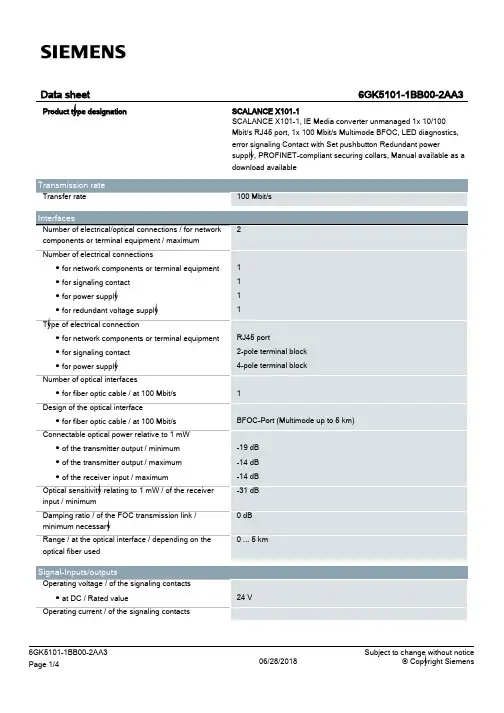
Haile科技之海乐于创新产品规格书型号:HSF-1100海乐康宁(北京)通信技术有限公司HAILE CORNING (Beijing) communication technology Co., LTDHSF-1100系列10/100M以太网光纤收发器产品概述:HSF-1100系列10/100M自适应以太网光纤收发器,可以将10/100Base-TX的双绞线电信号和100Base-FX的光信号进行相互转换。
它将网络的传输距离极限从铜线的100米扩展到120公里(单模光纤)。
典型应用是以太网距离互连,例如小区机房与城域网的连接。
由于具有自适应的功能,在与交换机连接时,交换机不需要任何设置。
HSF-1100系列收发器可作为一独立设备单独使用,也可作为一插入式模块安装于系列19英寸机架上,用于中心机房。
工业级导轨设计。
产品特性:☆支持IEEE802.3u.100BASE-T和100 BASE-FL协议☆支持全双工/半双工工作方式,并带有自动协商功能☆多模连接传输距离:2公里☆单模连接传输距离:20/40/60/80/100/120公里☆整机发热少,性能稳定可靠☆即插即用,可上14槽机架,卡式可以上16槽机架。
☆完备的LED状态指示,便于网络诊断和故障检查☆自动识别MD1/MD1-X交叉线和平行线☆良好的流量控制,带自复位功能,能有效防止死机现象出现技术参数:☆标准协议LEEE802.3Fast Ethernet 100Base-T和100Base-FL标准☆连接器一个UTP RJ-45连接器,一个SC/ST连接器☆指示灯PWR、FDX、FX LINK、TX LINK、TX LINK、TX ACT ☆工作方式全双工/半双工,具有全双工/半双工自动协商功能☆传输速率10M/100Mbps☆电源参数INPUT:110-260V AC 或48V DCOUTPUT:5V DC 1.2A☆储藏温度-20℃~70℃☆工作温度:-10℃~60℃☆相对温度5%~90%无冷凝☆ U TP线缆5类UTP,可长达100m、☆传输光纤多模:50/125,62.5,125or100/140um 单模:8.3/125,8.7/125,9/125or10/125um机械特性:尺寸:25(高)×70(宽)×105(深)mm(外置电源)30(高)×108(宽)×138(深)mm(内置电源)安装:工业级导轨安装,可上14槽机架,集中管理。
Huawei CX110 Switch Module V100R001C10White PaperIssue06Date2017-03-27Copyright © Huawei Technologies Co., Ltd. 2017. All rights reserved.No part of this document may be reproduced or transmitted in any form or by any means without prior written consent of Huawei Technologies Co., Ltd.Trademarks and Permissionsand other Huawei trademarks are trademarks of Huawei Technologies Co., Ltd.All other trademarks and trade names mentioned in this document are the property of their respective holders.NoticeThe purchased products, services and features are stipulated by the contract made between Huawei and the customer. All or part of the products, services and features described in this document may not be within the purchase scope or the usage scope. Unless otherwise specified in the contract, all statements, information, and recommendations in this document are provided "AS IS" without warranties, guarantees or representations of any kind, either express or implied.The information in this document is subject to change without notice. Every effort has been made in the preparation of this document to ensure accuracy of the contents, but all statements, information, and recommendations in this document do not constitute a warranty of any kind, express or implied.Huawei Technologies Co., Ltd.Address:Huawei Industrial BaseBantian, LonggangShenzhen 518129People's Republic of ChinaWebsite:About This DocumentPurposeThis document describes the E9000 CX110 GE switch module (CX110 for short) in terms ofits functions, advantages, appearance, specifications, internal networking, standards andcertifications. You can learn about the CX110 by reading this document.The product features and commands for the ethernet switching plane of the switch modulesvary according to the software version. For details, see the documents listed in the followingtable.Intended AudienceThis document is intended for:l Huawei presales engineersl Channel partner presales engineersl Enterprise presales engineersSymbol ConventionsThe symbols that may be found in this document are defined as follows:Change HistoryIssue 06 (2017-03-17)This issue is the third official release.Issue 05 (2017-02-17)This issue is the fifth official release.Issue 04 (2016-11-22)This issue is the fourth official release.Issue 03 (2016-05-12)This issue is the third official release.Issue 02 (2015-07-17)This issue is the second official release.Issue 01 (2015-02-16)This issue is the first official release.White Paper ContentsContentsAbout This Document (ii)1 Introduction (1)1.1 Function (2)1.2 Advantages (8)1.3 Appearance (9)1.4 Ports (13)1.5 Indicator (17)1.6 Internal Chassis Networking (19)1.7 Software and Hardware Compatibility (21)1.8 Technical specifications (23)2 Standards and Certifications (26)2.1 Standards Compliance (27)2.2 Certifications (29)1 Introduction About This Chapter1.1 FunctionThis topic describes the functions, protocols, and ports of the CX110 GE switch module.1.2 AdvantagesThe CX110 provides various ports (GE/10GE/40GE) and high specifications, and supportslarge data center networks, high-performance stacking, and various data center features. Inaddition, the CX110 switch module can be easily deployed and maintained.1.3 AppearanceThis topic describes the CX110 in terms of its appearance, panel, and installation positions inthe chassis.1.4 PortsThis topic describes the features, number rules, names, types, quantities, subcard numbers,and port numbers of the CX110 ports.1.5 IndicatorThis topic describes the indicators on the CX110.1.6 Internal Chassis NetworkingThis topic describes connection relationships between the CX110 and mezz modules oncompute nodes.1.7 Software and Hardware CompatibilityThis topic describes mezz modules that can work with the CX110 and pluggable modules andcables supported by ports on the CX110 panel.1.8 Technical specificationsThis topic describes the physical, environmental, power, and network switching specificationsof the CX110.1.1 FunctionThis topic describes the functions, protocols, and ports of the CX110 GE switch module.The CX110 GE switch module (CX110 for short) is a switch control unit that provides dataswitching function for service slots in the system and centrally provides service andmanagement ports for external devices.The CX110 is installed in the rear slot of the E9000 chassis and connected to compute nodes,storage nodes, management modules through the E9000 midplane. The CX110 performsswitching of internal data packets and control management packets to provide high-speed datatransmission.Table 1-1 describes the functions of the CX110.Table 1-1 GE switching plane function description1.2 AdvantagesThe CX110 provides various ports (GE/10GE/40GE) and high specifications, and supportslarge data center networks, high-performance stacking, and various data center features. Inaddition, the CX110 switch module can be easily deployed and maintained.Various Ports (GE/10GE/40GE)Underpinned by the leading hardware platform, the CX110 provides high-density ports andand a line-speed forwarding capability.The CX110 provides four 10GE ports and 12 GE electrical ports for connecting upstream toconvergence/core switches, 34 GE ports for interconnecting with high-performance computenodes, and two 40GE ports for interconnecting with and stacking switch boards.High Specifications and Support for Large Data Center NetworksThe CX110 provides the highest specifications in the industry. It supports a maximum of131,072 MAC addresses, a maximum of 16,384 forwarding information bases (FIBs), and amaximum of 4,096 multicast prefix tables.High-Performance Stacking, Easy Deployment and MaintenanceThe CX110 supports stacking of four devices. It has the following advantages:l High performance: A single stacking system can provide eight 10GE and 24 GE uplink ports (two devices are stacked).l High bandwidth: The CX110 supports 80GE stacking bandwidth. The stacking system has no bandwidth bottlenecks.l Easy deployment and maintenance:–Pre-deployment and offline configuration are supported. The system can be pre-planned and pre-configured. Devices can be added as required, supporting plug andplay and Pay As You Grow.–The slot ID of a device is the ID in a stacking system, facilitating deviceidentification and maintenance.–Indicators on the front panel indicate the role and status of a stacking system. Thestacking system can be maintained without a terminal.l Simple upgrade operations: The stacking system supports quick and automatic software upgrades, simplifying upgrade operations and reducing upgrade workload.Various Data Center Featuresl Virtual/virtual machine (VM) access–Supports virtualized servers, improving data center utilization.–Supports virtual resource discovery. During migration of VMs, VM networkpolicies can be automatically migrated using the virtual resource discovery functionso that network resources can be allocated as required. Working with the large-scalelayer 2 network, VMs can be freely migrated inside the whole data center.l Transparent Interconnection of Lots of Links (TRILL) protocol–Complying with the Internet Engineering Task Force (IETF) standard, the TRILLprotocol supports ultra-large networks and flexible networking modes.–The TRILL protocol supports load balancing by paths, so that traffic can be sharedbetween multiple paths according to service requirements.–The TRILL protocol supports sub-second network convergence. Any changes onthe network can be quickly sensed and then fast convergence is performed.1.3 AppearanceThis topic describes the CX110 in terms of its appearance, panel, and installation positions inthe chassis.AppearanceFigure 1-1 shows the CX110.Figure 1-1 AppearanceInstallation PositionsThe CX110 can be installed in the four slots at the rear of the E9000 chassis. The four slots are 1E, 2X, 3X, and 4E, as shown in Figure 1-2.Figure 1-2 Installation positions and slot numberingPanelFigure 1-3 shows the CX110 panel.Figure 1-3 Panel1Product model 2Customization label (with an ESN label)3Stacking status indicator 4Health status indicator 5Offline button/indicator 6BMC serial port 7GE electrical port810GE optical port9Data transmission status indicator of the 10GE optical port 10Connection status indicator of the 10GE optical port 11GE electrical port indicator12SYS serial portThe numbers on the left side are port serial numbers. The arrow direction of a triangle indicates the direction of a port.ESNsAn Equipment Serial Number (ESN) is a string that uniquely identifies a server. An ESN is required when you apply for technical support from Huawei.Figure 1-4 shows the ESN format.Figure 1-4 ESN example1.4 PortsThis topic describes the features, number rules, names, types, quantities, subcard numbers,and port numbers of the CX110 ports.The CX110 Ethernet ports are numbered in Slot number/Subcard number/Port numberformat.l Slot number: indicates the slot number of the current switch module. The value ranges from 1 to 4, mapping to 1E, 2X, 3X, and 4E slot respectively from left to right on thepanel.l Subcard number: indicates the number of a subcard supported by service ports. Thevalue ranges from 1 to 20. Table 1-2 and Table 1-3 describe subcard numbers.l Port number: indicates the sequence number of a port on a subcard. Table 1-2 and Table 1-3 describe port numbers and subcards.For example, if the CX110 is in slot 2X, the first GE port on the upper right on the panel isnumbered as GE 2/17/12, as shown in Figure 1-5.Figure 1-5 Port naming rulesTable 1-2 describes the external ports on the CX110.Table 1-2 External portsTable 1-3 describes the internal ports on the CX110. Table 1-3 Internal ports1.5 IndicatorThis topic describes the indicators on the CX110.You can observe the indicators to determine the current operating status of the CX110. Table1-4 describes the indicators.Table 1-4 Indicator description1.6 Internal Chassis NetworkingThis topic describes connection relationships between the CX110 and mezz modules oncompute nodes.For details about the networking of the CX110 and Mezz cards on compute nodes, see E9000Blade Server Mezz Module-Switch Module Interface Mapping Tool.Figure 1-6 shows the internal chassis networking for the CX110 and compute nodes. Ports oncompute nodes for connecting to the CX110 are provided by two mezz modules as follows:l Mezz 1 connects to GE switching planes of the CX110s in slots 2X and 3X.l Mezz 2 connects to GE switching planes of the CX110s in slots 1E and 4E.Figure 1-6 Mapping between the CX110 and mezz modules on compute nodesThe following describes the mapping between the CX110s and mezz modules. For example,the CX110s are installed in slots 2X and 3X and connect to Mezz 1.Port Mapping Between a Switch Module and a Mezz ModuleMapping between the CX110 and ports on the MZ110The MZ110 provides four GE ports, including ports 1, 2, 3, and 4. Ports 1 and 2 map to theGE switching plane of the CX110 in slot 2X, and ports 3 and 4 map to the GE switching planeof the CX110 in slot 3X, as shown in Figure 1-7.Figure 1-7 Mapping between the CX110 and ports on the MZ110Mapping between the CX110 and ports on the MZ111The MZ111 provides four GE ports, including ports 1, 2, 3, and 4. Ports 1 and 3 map to theGE switching plane of the CX110 in slot 2X, and ports 2 and 4 map to the GE switching planeof the CX110 in slot 3X, as shown in Figure 1-8.Figure 1-8 Mapping between the CX110 and ports on the MZ1111.7 Software and Hardware CompatibilityThis topic describes mezz modules that can work with the CX110 and pluggable modules andcables supported by ports on the CX110 panel.For details about the software and hardware that are compatible with the CX110, see HuaweiServer Compatibility Checker.Supported Mezz ModulesThe CX110 connects to mezz modules of compute nodes. Table 1-5 describes models andspecifications of the supported mezz modules.Table 1-5 Supported mezz modulesSupported Pluggable Modules and CablesTable 1-6 Supported pluggable modules and cablesCX110 supports multiple pluggable optical modules, fibers, and network cables. You canchoose the modules and cables based on site requirements.l The CX110 provides the following functions for uplink GE applications:–Provides SFP+ optical ports and supports single-mode and multi-mode SFP opticalmodules.–Provides RJ45 ports, supports 10/100/1000 Mbit/s autonegotiation, and uses twistedpair cables for connection.l The CX110 provides the following functions for uplink 10GE applications:–Provides SFP+ optical ports and supports single-mode and multi-mode SFP+optical modules.–Supports SFP+ 10GE cables, which can be 7 m or 10 m active high-speed cables or1 m, 3 m, or 5 m passive high-speed cables.1.8 Technical specificationsThis topic describes the physical, environmental, power, and network switching specificationsof the CX110.Table 1-7 describes the technical specifications of the CX110, and Table 1-8 describes thenetwork switching specifications of the CX110.Table 1-7 Technical specificationsTable 1-8 Network switching specificationsWhite Paper 1 Introduction2 Standards and Certifications About This Chapter2.1 Standards ComplianceThis topic describes the international and industrial standards and communication protocolsthat the CX110 complies with.2.2 CertificationsThis topic describes the certifications that the E9000 has passed.2.1 Standards ComplianceThis topic describes the international and industrial standards and communication protocolsthat the CX110 complies with.International StandardsTable 2-1 lists the international standards.Table 2-1 Standards and protocol complianceIndustrial StandardsTable 2-2 lists the industrial standards.Table 2-2 Industrial standardsCommunication ProtocolsTable 2-3 lists the communication protocols.Table 2-3 Communication protocols2.2 CertificationsThis topic describes the certifications that the E9000 has passed.Table 2-4 lists the certifications.Table 2-4 Certifications。
鍚勭PLC閫氳浠嬭川鍜屽崗璁粙缁?鑷粠绗竴鍙癙LCPLC鍦℅M鍏徃姹借溅鐢熶骇绾夸笂棣栨搴旂敤鎴愬姛浠ユ潵锛孭LC鍑€熷叾鏂逛究鎬с€佸彲闈犳€т互鍙婁綆寤夌殑浠锋牸寰楀埌浜嗗箍娉涚殑搴旂敤銆備絾PLC姣曠珶鏄竴涓粦鐩掑瓙锛屼笉鑳藉疄鏃剁洿瑙傚湴瑙傚療鎺у埗杩囩▼锛屼笌DCS鐩告瘮瀛樺湪姣旇緝澶х殑宸窛銆傝绠楁満鎶€鏈殑鍙戝睍鍜屾櫘鍙婏紝涓篜LC鍙堟彁渚涗簡鏂扮殑鎶€鏈墜娈碉紝閫氳繃璁$畻鏈哄彲浠ュ疄鏂界洃娴婸LC鐨勬帶鍒惰繃绋嬪拰缁撴灉锛岃PLC濡傝檸娣荤考銆備絾鏄悇PLC閫氳浠嬭川浠嬭川鍜岄€氳鍗忚鍗忚鍚勪笉鐩稿悓锛屼笅闈㈠皢绠€鍗曚粙缁嶄富瑕丳LC鐨勯€氳浠嬭川鍜屽崗璁唴瀹广€? 缇庣郴鍘傚Rockwell AB Rockwell鐨凱LC涓昏鏄寘鎷琍LC2銆丳LC3銆丳LC5銆丼LC500銆丆ontrolLogix绛夊瀷鍙凤紝PLC2鍜孭LC3鏄棭鏈熷瀷鍙凤紝鐜板湪鐢ㄧ殑姣旇緝澶氱殑灏忓瀷PLC鏄疭LC500锛屼腑鍨嬬殑涓€鑸槸ControlLogix锛屽ぇ鍨嬬殑鐢≒LC5绯诲垪銆? DF1鍗忚鏄疪ockwell鍚凱LC閮芥敮鎸佺殑閫氳鍗忚锛孌F1鍗忚鍙互閫氳繃232鎴?22绛変覆鍙d粙璐ㄨ繘琛屾暟鎹紶杈擄紝涔熷彲浠ラ€氳繃DH銆丏H+銆丏H485銆丆ontrolNet绛夌綉缁滀粙璐ㄦ潵浼犺緭銆侱F1鍗忚鐨勫叿浣撳唴瀹瑰彲浠ュ湪AB鐨勮祫鏂欏簱涓笅杞姐€? AB鐨刾lc涔熸彁渚涗簡OPC鍜孌DE锛屽叾闆嗘垚鐨勮蒋浠朵腑RSLogix涓氨鍖呭惈DDE鍜孫PC SERVER锛屽彲浠ラ€氳繃涓婅堪杞欢鏉ヨ繘琛屾暟鎹€氳銆? AB鐨勪腑楂樻。
鐨凱LC杩樻彁渚涗簡楂樼骇璇█缂栫▼鍔熻兘锛岀敤鎴疯繕鍙互閫氳繃缂栫▼瀹炵幇鑷繁鐨勯€氳鍗忚銆? GE GE鐜板湪鍦ㄥ浗鍐呯敤鐨勬瘮杈冨鐨勪富瑕佹槸90-70鍜?0-30绯诲垪plc锛岃繖涓ゆPLC閮芥敮鎸丼NP鍗忚锛孲NP鍗忚鍦ㄥ叾PLC鎵嬪唽涓湁鍗忚鐨勫叿浣撳唴瀹广€? 鐜板湪GE鐨凱LC涔熷彲浠ラ€氳繃浠ュお缃戦摼鎺ワ紝GE鐨勪互澶綉鍗忚鍐呭涓嶅澶栧叕寮€锛屼絾GE鎻愪緵浜嗕竴涓猄DK寮€鍙戝寘锛屽彲浠ュ熀浜庤寮€鍙戝寘閫氳銆? 娆ф床绯诲垪瑗块棬瀛? 瑗块棬瀛愮郴鍒桺LC涓昏鍖呮嫭鍏舵棭鏈熺殑S5鍜岀幇鍦ㄧ殑S7-200銆丼7-300銆丼7-400绛夊悇鍨嬪彿PLC锛屾棭鏈熺殑S5PLC鏀寔鐨勬槸3964R鍗忚锛屼絾鏄洜涓虹幇鍦ㄥ湪鍥藉唴搴旂敤杈冨皯锛岄櫎鏋佷釜鍒敼閫犻」鐩锛屽緢灏戞湁涓庡叾杩涜鏁版嵁閫氳鐨勩€? S7-200鏄タ闂ㄥ瓙灏忓瀷PLC锛屽洜涓哄叾浣庡粔鐨勪环鏍煎湪鍥藉唴寰楀埌浜嗗ぇ瑙勬ā鐨勫簲鐢紝鏀寔MPI銆丳PI鍜岃嚜鐢遍€氳鍙e崗璁€? 瑗块棬瀛?00鐨凱LC鏀寔MPI锛岃繕鍙互閫氳繃PROFIBUS鍜屽伐涓氫互澶綉鎬荤嚎绯荤粺鍜岃绠楁満杩涜閫氳銆傚鏋滆瀹屾垚鐐瑰鐐归€氳锛屽彲浠ヤ娇鐢–P340/341銆? S7400浣滀负瑗块棬瀛愮殑澶у瀷PLC锛屾彁渚涗簡鐩稿綋瀹屽鐨勯€氳鍔熻兘銆傚彲浠ラ€氳繃S7鏍囧噯鐨凪PI杩涜閫氳锛屽悓鏃跺彲浠ラ€氳繃C-鎬荤嚎锛孭ROFIBUS鍜屽伐涓氫互澶綉杩涜閫氳銆傚鏋滆浣跨敤鐐瑰鐐归€氳锛孲7-400闇€瑕侀€氳繃CP441閫氳妯″潡銆? 瑗块棬瀛愮殑閫氳鍗忚娌℃湁鍏紑锛屽寘鎷传閲戞ˉ缁勬€佽蒋浠跺湪鍐呰澶氱粍鎬佽蒋浠堕兘鏀寔MPI銆丳PI绛夐€氳鏂瑰紡锛孭ROFIBUS鍜屽伐涓氫互澶綉涓€鑸€氳繃瑗块棬瀛愮殑杞欢杩涜鏁版嵁閫氳銆? 鏂借€愬痉锛堣帿杩悍锛? 鏂借€愬痉鐨凱LC鍨嬪彿姣旇緝澶氾紝鍦ㄥ浗鍐呭簲鐢ㄤ篃姣旇緝澶氥€傚叾閫氳鏂瑰紡涓昏鏄敮鎸丮ODBUS鍜孧ODBUS PLUS涓ょ閫氳鍗忚銆? MODBUS鍗忚鍦ㄥ伐鎺ц涓氬緱鍒颁簡骞挎硾鐨勫簲鐢紝宸蹭笉浠呬粎鏄竴涓狿LC鐨勯€氳鍗忚锛屽湪鏅鸿兘浠〃锛屽彉棰戝櫒绛夎澶氭櫤鑳借澶囬兘鏈夌浉褰撳箍娉涚殑搴旂敤銆侻ODBUS缁忚繃杩涗竴姝ュ彂灞曪紝鐜板湪鍙堟湁浜哅ODBUS TCP鏂瑰紡锛岄€氳繃浠ュお缃戞柟寮忚繘琛屼紶杈擄紝閫氳閫熷害鏇村揩銆? MODBUS PLUS鐩稿浜嶮ODBUS浼犻€侀€熷害鏇村揩锛岃窛绂绘洿杩滐紝璇ラ€氳鏂瑰紡闇€瑕佸湪璁$畻鏈轰笂瀹夎MODCON鎻愪緵鐨凷A85鍗″苟闇€瀹夎璇ュ崱鐨勯┍鍔ㄦ墠鍙互杩涜閫氳銆? 闄や簡涓婅堪涓ょ鏂瑰紡涔嬪锛岃帿杩悍鐨凱LC杩樻敮鎸佸TCP/IP浠ュお缃戯紝Unitelway锛?FIPWAY锛孎IPIO锛孉S-I锛孖nterbus-s绛夊绉嶉€氳鏂瑰紡銆?鏃ョ郴PLC 娆у榫? 娆у榫欑郴鍒桺LC鍦ㄤ腑鍥芥帹骞跨殑涔熸瘮杈冨銆傚湪閫氳鏂瑰紡涓婏紝OMRON鐜板湪涓昏閲囩敤涓ょ閫氳鏂瑰紡锛?Host Link鍗忚鏄熀浜庝覆鍙f柟寮忚繘琛屾暟鎹紶杈撶殑閫氳鏂瑰紡銆傚綋PLC杩涘叆MONITOR鏂瑰紡鏃讹紝涓婁綅鏈哄彲浠ュ拰娆у榫橮LC閫氳銆傚湪鍜屾濮嗛緳閫氳鏃惰娉ㄦ剰锛屼袱娆¢€氳涔嬮棿瑕佺暀涓€瀹氭椂闂达紝濡傛灉閫氳閫熷害杩囧揩瀹规槗閫犳垚PLC閫氳寮傚父銆? ControlLink鏄濮嗛緳PLC鐨勪竴绉嶅揩閫熼€氳鏂瑰紡銆侰ontrol Link閫氳繃鏉垮崱杩涜鏁版嵁閫氳锛屾澘鍗′箣闂存湁鏁版嵁浜ゆ崲鍖猴紝鐢辨澘鍗″疄鐜版暟鎹殑浜ゆ崲浠庤€屽畬鎴愭暟鎹噰闆嗗姛鑳姐€備娇鐢ㄨ鏂瑰紡閫氳闇€閰嶇疆娆у榫欑殑椹卞姩銆? 涓夎彵涓夎彵PLC鐨勫皬鍨婸LC鍦ㄥ浗鍐呯殑搴旂敤闈炲父骞挎硾銆備笁鑿辩殑PLC鍨嬪彿涔熸瘮杈冨锛屼富瑕佸寘鎷現X绯诲垪锛孉绯诲垪鍜孮绯诲垪銆備笁鑿辩郴鍒桺LC閫氳鍗忚鏄瘮杈冨鐨勶紝鍚勭郴鍒楅兘鏈夎嚜宸辩殑閫氳鍗忚銆傚FX绯诲垪涓氨鍖呮嫭閫氳繃缂栫▼鍙f垨232BD閫氳锛屼篃鍙互閫氳繃485BD绛夋柟寮忛€氳銆傚叾A绯诲垪鍜孮绯诲垪鍙互閫氳繃浠ュお缃戦€氳銆傚綋鐒讹紝涓夎彵鐨凱LC杩樺彲浠ラ€氳繃CC-LINK鍗忚閫氳銆? 鏉句笅鏉句笅PLC鍜岃绠楁満涔嬮棿鍙互閫氳繃涓插彛鍜屼互澶綉杩涜閫氳銆傚叾閲囩敤鐨勯€氳鍗忚鏄疢EWTOCOL鍗忚銆傚澶у鏁版棩绯籔LC涓€鏍凤紝MEWTOCOL鍗忚姣旇緝绠€鍗曘€傚寘鎷传閲戞ˉ缁勬€佽蒋浠跺湪鍐呯殑璁稿杞欢閮藉彲浠ヤ粠PLC涓洿鎺ヨ鍙栨暟鎹€? 浠ヤ笂浠嬬粛鐨勬槸鍥藉鐨勪富娴丳LC璁惧閫氳鏂瑰紡銆傞櫎浠ヤ笂鍘傚澶栵紝杩樻湁寰堝PLC鍘傚锛? 鍘傚鍨嬪彿鍗忚浠嬭川LG STER-K10S/30S/60S/80S/K200S MASTER-K 涓插彛鏃ョ珛H绯诲垪 EH150绛? Hi鍗忚涓插彛/USB 鍏夋磱鎵€鏈夌郴鍒? CCM2鍗忚涓插彛淇℃嵎鎵€鏈夌郴鍒? MODBUS 涓插彛鍑开鎭? 鍏ㄩ儴MODBUS 涓插彛浠ヤ笂鍝佺墝鍜屽瀷鍙风殑PLC绱噾妗ヨ蒋浠堕兘鍙互鏀寔鍜屽叾閫氳锛岀敤鎴蜂笉闇€瑕佸啀缂栧啓绋嬪簭銆侾LC鍘傚鍜屽瀷鍙蜂篃鍦ㄤ笉鏂闀垮拰鍙戝睍锛岄毦鍏嶇枏婕忎箣澶勶紝甯屾湜澶у鎵硅瘎鎸囨骞惰ˉ鍏呫€?。
10/100M单端口快速以太网收发器特性●10/100Mbps的TX●全双工或半双工●支持自动的MDI/MDIX(介质相关交叉)功能●完全符合IEEE●支持IEEE 自动协商●支持MII / RMII / SNI接口●IEEE 全双工控制规范●支持自动省电模式●支持基线漂移(BLW)补偿●支持中断功能●支持中继模式●内置的调节器提供电源●基于DSP的PHY收发器技术●使用25MHz的晶体振荡器或50MHz振荡的ref_clk信号作为时钟源●灵活的LED显示速度、双工、链接、活动和碰撞状态●通过 MDC和MDIO与其他MAC通信时支持流量控制● CMOS技术,●48引脚LQFP封装●支持无铅封装(请参阅订单信息)一般说明IP101A LF是一个IEEE 兼容的单端口10/100Mbps快速以太网收发器。
它支持自动的MDI/MDIX功能以简化网络安装和减少系统维护成本。
为了提高系统的性能,IP101A提供了一个硬件中断引脚指示链接、速度和双工状态的变化。
IP101A还提供媒体独立接口(MII)/串行网络接口(SNI)或简化媒体独立接口(RMII)连接不同类型的10/100Mbps的媒体访问控制器(MAC)。
IP101A LF设计使用5类非屏蔽双绞线电缆连接到其它局域网设备。
IP101A LF收发器是用先进的CMOS技术制造的,该芯片只需要的电源并在自动节能模式消耗非常低的功率。
IP101A LF可以实现网络用双绞线RJ-45接口适配器连接。
它也可以很容易地实现集线器、交换机、路由器、接入点。
特性总则目录修订历史接收和发送数据的路径框图引脚定义1引脚描述2寄存器描述3功能描述4串行管理界面5晶体规格6布局准则7电气特性直流特性7.1.1绝对最大额定值7.1.2功率消耗7.1.3操作条件7.1.4电源电压交流特性7.2.1 MII定时时序7.2.2 RMII定时时序7.2.3 SMI定时时序8订单信息9封装和机械规范接收和发送数据的路径框图图1:IP101A LF的流程图引脚配置图2:IP101A LF引脚分配1、引脚描述2、寄存器描述注意:Register 2和register 3标识寄存器一起构成供应商模型、模型版本号和组织唯一标识符(OUI)信息。
110配线架详解配线架是电缆或光缆进行端接和连接的装置。
在配线架上可进行互连或交接操作。
建筑群配线架是端接建筑群干线电缆、光缆的连接装置。
建筑物配线架是端接建筑物干线电缆、干线光缆并可连接建筑群干线电缆、干线光缆的连接装置。
楼层配线架水平电缆、水平光缆与其他布线子系统或设备相连接的装置。
光纤配线架在后面部份还会单独介绍,这里介绍的都是铜缆配线架。
铜缆配线架系统分110型配线架系统和模块式快速配线架系统。
110型连接管理系统由AT&T公司于1988年首先推出,该系统后来成为工业标准的蓝本。
110型连接管理系统基本部件是配线架、连接块、跳线和标签。
110型配线架是110型连接管理系统核心部份,110配线架是阻燃、注模塑料做的基本器件,布线系统中的电缆线对就端接在其上。
110型配线架有25对、50对、100对、300对多种规格,它的套件还应包括4对连接块或5对连接块(图1-24)、空白标签和标签夹(图1-25)、基座。
110型配线系统使用方便的插拔式快接式跳接可以简单也进行回路的重新排列,这样就为非专业技术人员管理交叉连接系统提供了方便。
110型配线架主要有以下类型:110AW2:100对和300对连接块,带腿。
110DW2:25对、50对、100对和300对接线块,不带腿。
110AB:100对和300对带连接器的终端块,带腿。
110PB-C:150对和450对带连接器的终端块,不带腿。
110AB:100对和300对接线块,带腿。
110BB:100对连接块,不带腿。
110型配线架的缺点是不能进行二次保护,所以在入楼的地方需要考虑安装具有过流、过压保护装置的配线架。
110型配线架主要有五种端接硬件类型。
110A型、110P型、110JP 型、110VP VisiPatch型和XLBET超大型。
110A、110P、110JP、110VP VisiPatch和XLBET系统具有相同的电气性能,但是其性能、规格及占用的墙场或面板大小则有所不同。
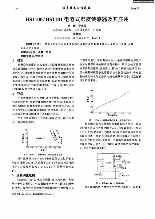
湿度传感器HS11011引言湿度传感器是根据某种物质从其周围空气中吸收水分后引起的物理或化学性质的变化,从而获得该物质的吸水量和周围空气的湿度。
湿度传感器分为电阻式和电容式两种,产品的基本形式都是在基片涂覆感湿材料形成感湿膜。
空气中的水蒸汽吸附于感湿材料后,元件的阻抗、介质常数发生很大的变化,从而制成湿敏元件。
湿敏电容一般是用高分子薄膜电容制成的,由于它具有灵敏度高、产品互换性好、响应速度快、湿度的滞后量小、便于制造、容易实现小型化和集成化,其精度一般比湿敏电阻要低一些。
但电阻对温度的敏感因而限制了器件在较大温度范围内的应用,因而电容湿度传感器越来越受到重视。
2 湿敏元件及变送器芯片特性目前,生产湿敏电容的主要厂家是法国Humirel 公司。
它生产的HS1101 测量范围是0%,100%RH,电容量由162PF 变到200PF,其误差不大于?2%RH;响应时间小于5S;湿度系数为0.34PF/?;年漂移量0.5%RH/年,长期稳定。
图1 为HS1101湿敏电容的湿度-电容响应曲线。
湿度变送器采用了美国 BB 公司生产的XTR105芯片,该变送器具有以下特点:a 工作范围宽;b 测量精度高;c 电路简单;d 可靠性好,使用寿命长;e 抗干扰能力强;f 工作温度范围宽(-40,+85?)3 湿度测量电路HS1101在电路中相当于一个电容器件,它的电容量随着所测空气湿度的增加而增大,为了能将电容的变化转换成电压的变化,我们设计了振荡电路、消除零点电容影响电路、整流电路、积分电路、电压—电流转换电路、放大电路等,其工作原理简图如图2 所示。
3.1 振荡电路振荡电路的作用是将电容的变化量转化为频率可变的方波。
由图3 可知,这是一个非对称多谐振荡器。
或非门G1 工作在电压传输特性的转折区,把它的输出电压直接连接到或非门G2 的输入端。
G2即可得到一个介于高低电平之间的静态偏置电压,从而使G2 的静态工作点也处于电压传输特性转折区上。
HG110用户手册目录1注意事项 (1)2简介 (2)3面板及使用说明 (3)3.1前面板图以及指示灯状态说明 (3)3.2后面板图以及接口说明 (3)3.3硬件连接 (4)4用户配置使用说明 (5)4.1安装光盘使用说明 (5)4.2宽带上网使用步骤 (8)4.3登陆前准备 (8)4.4登陆 (10)4.5状态 (10)4.5.1设备基本信息 (11)4.5.2网络侧信息 (11)4.6网络 (14)4.6.1宽带设置 (14)4.6.23G上行手动连接 (17)4.6.3WLAN配置 (19)4.7安全 (21)4.7.1网页过滤 (22)4.7.2防火墙 (22)4.7.3MAC地址过滤 (23)4.8管理 (25)4.8.1用户管理 (25)4.8.2设备管理 (25)4.9帮助 (26)5常见问题解答 (27)6技术规格 (28)7附录:缩略语 (29)1 注意事项在使用本设备前,请仔细阅读下面的注意事项:请使用说明书标记的电源类型。
请使用在设备包装中的电源适配器。
注意电源输出的插座或延长线。
过重负载的电源输出或损坏的线和插座可能会造成电击或火灾事故。
请经常检查电源线。
如果您发现电源线有任何的损坏,请立即更换新的电源线。
要留出的适当的空间来供设备散热,避免设备因过度发热而造成损伤。
设备上的长条孔是为了使设备更好地散热而设计的。
请不要盖住这些散热孔。
不要把设备放置在靠近热源出口或高温地地方。
避免设备受到阳光的直接照射。
不要把设备放置在潮湿的地方。
不要让设备沾到各种液体。
在没有我们的客户工程师或您的宽带提供者的指引下,请不要将设备连接到任何个人的计算机或电子产品,因为任何错误的连接可能会导致电源损坏或火灾危险。
不要将设备放到在不稳定的平面上。
2 简介尊敬的客户:HG110设备是一款方便、灵活、标准、高集成度的宽带综合接入设备。
它可为个体用户,SOHO(小型办公室或家庭式办公室),小型企业等提供高性能的接入服务。