模块机组安装指南
- 格式:ppt
- 大小:1000.50 KB
- 文档页数:34
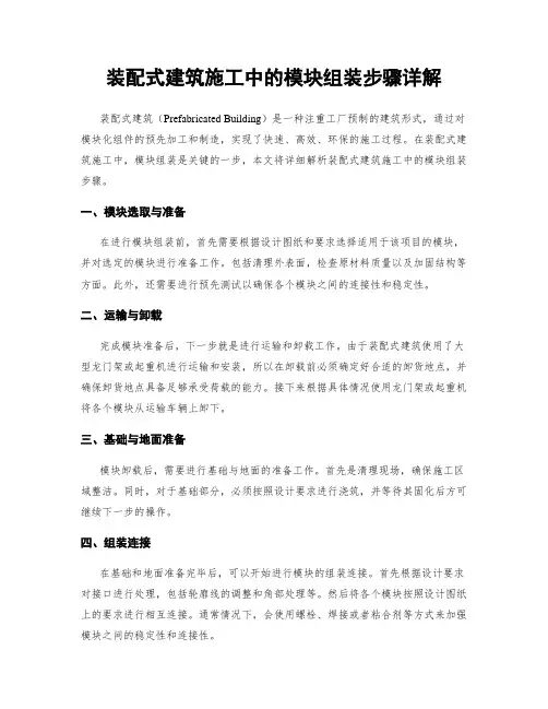
装配式建筑施工中的模块组装步骤详解装配式建筑(Prefabricated Building)是一种注重工厂预制的建筑形式,通过对模块化组件的预先加工和制造,实现了快速、高效、环保的施工过程。
在装配式建筑施工中,模块组装是关键的一步,本文将详细解析装配式建筑施工中的模块组装步骤。
一、模块选取与准备在进行模块组装前,首先需要根据设计图纸和要求选择适用于该项目的模块,并对选定的模块进行准备工作。
包括清理外表面,检查原材料质量以及加固结构等方面。
此外,还需要进行预先测试以确保各个模块之间的连接性和稳定性。
二、运输与卸载完成模块准备后,下一步就是进行运输和卸载工作。
由于装配式建筑使用了大型龙门架或起重机进行运输和安装,所以在卸载前必须确定好合适的卸货地点,并确保卸货地点具备足够承受荷载的能力。
接下来根据具体情况使用龙门架或起重机将各个模块从运输车辆上卸下。
三、基础与地面准备模块卸载后,需要进行基础与地面的准备工作。
首先是清理现场,确保施工区域整洁。
同时,对于基础部分,必须按照设计要求进行浇筑,并等待其固化后方可继续下一步的操作。
四、组装连接在基础和地面准备完毕后,可以开始进行模块的组装连接。
首先根据设计要求对接口进行处理,包括轮廓线的调整和角部处理等。
然后将各个模块按照设计图纸上的要求进行相互连接。
通常情况下,会使用螺栓、焊接或者粘合剂等方式来加强模块之间的稳定性和连接性。
五、管道与电气安装完成模块组装后,需要对管道与电气系统进行安装工作。
这些系统包括给水管道、排水管道、电力供应系统等。
在安装过程中,需按照设计要求放置各种设备和配件,并确保其正确连接和固定。
六、室内外饰面除了基本建筑结构外,室内外饰面也是装配式建筑中不可忽视的环节。
这一步需要进行墙体涂料、地板铺设、天花板安装等工作。
同时,还需要考虑相应的保温和隔音措施,以提高建筑的性能和舒适度。
七、功能收尾模块组装接近尾声时,还需要进行一些功能性的收尾工作。
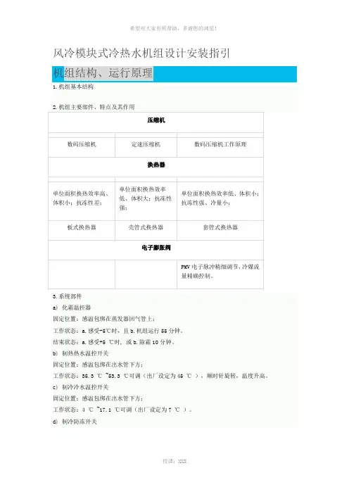
风冷模块式冷热水机组设计安装指引3.系统部件a)化霜温控器固定位置:感温包绑在蒸发器回气管上;工作状态:a.感受-5℃时,且b.机组运行55分钟。
结束状态:a.感受+5 ℃时, 或b.除霜10分钟。
b)制热热水温控开关固定位置:感温包绑在出水管下方;工作状态:35.3 ℃ ~53.3 ℃可调(出厂设定为45 ℃),顺时针旋转,温度升高。
c)制冷冷水温控开关固定位置:感温包绑在出水管下方;工作状态:4 ℃ ~17.1 ℃可调(出厂设定为7 ℃)。
d)制冷防冻开关设计、安装指引水管连接将水管接到机组一侧的进水、出水口。
供水系统应注意以下事项:1)循环水采用软化水。
2)水流量不能低于机组标称值。
3)需配备适当流量和压头的水循环泵。
4)建议安装有适当容量的绝热贮水箱,以免负荷太小,频繁启动机组而降低压缩机的使用寿命。
5)必须有供水安全阀门。
6)必须配备膨胀水箱,以适应供水系统中因气温变化而造成的水体积的变动。
7)排气阀门必须设置在机组进出水管连接处。
8)将截止阀设在机组进出水连接管处。
9)在水系统最低点设定合适的排水塞或开关。
10)水管必须绝热,以防止热量散失和冷凝水凝固。
11)机组出厂时已配有水流开关,用户无需自行配备。
12)水系统安装请参考“水系统安装图”安装。
(见下图)13)随机多附带一个水过滤网,在调试完毕后,请更换水过滤网。
14)在注水前,应确保管道中不会有沙粒、石子、生锈的铁屑、脱落的锡焊渣或其它杂质,以免损坏热交换器。
冲洗供水系统时,建议旁通该机。
水过滤器应当安装在机组回水管上。
15)对水系统,要求客户每半个月检查一次。
1.多台25/30/35KW并联,同程式连接(推荐)2.多台25/30/35KW并联,同程式连接(不推荐)3.65KW总出水感温包安装位置说明:1)<7个模块以内的连接方式,同程式连接(推荐):2)<7个模块以内的连接方式,同程式连接(不推荐):4.8-16个模块的连接方式,左右并行连接;同程式连接(推荐):5.8-16个模块的连接方式,前后并行连接;同程式连接(推荐):6.8-16个模块的连接方式,前后并行连接;同程式连接(推荐):建议使用两个线控器分别对两个水泵控制。
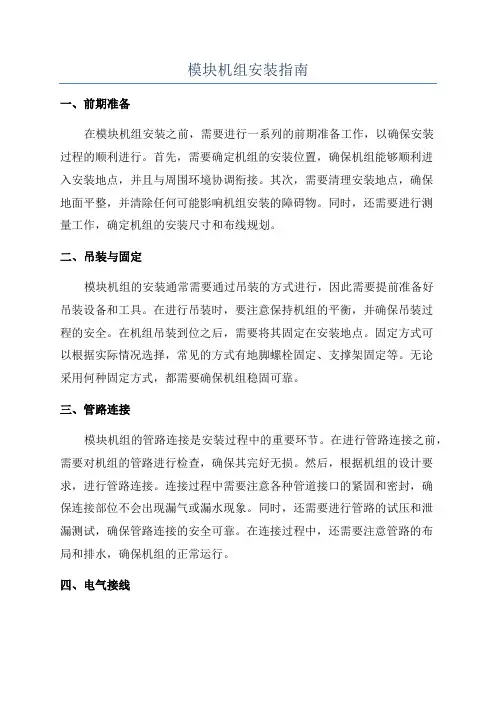
模块机组安装指南一、前期准备在模块机组安装之前,需要进行一系列的前期准备工作,以确保安装过程的顺利进行。
首先,需要确定机组的安装位置,确保机组能够顺利进入安装地点,并且与周围环境协调衔接。
其次,需要清理安装地点,确保地面平整,并清除任何可能影响机组安装的障碍物。
同时,还需要进行测量工作,确定机组的安装尺寸和布线规划。
二、吊装与固定模块机组的安装通常需要通过吊装的方式进行,因此需要提前准备好吊装设备和工具。
在进行吊装时,要注意保持机组的平衡,并确保吊装过程的安全。
在机组吊装到位之后,需要将其固定在安装地点。
固定方式可以根据实际情况选择,常见的方式有地脚螺栓固定、支撑架固定等。
无论采用何种固定方式,都需要确保机组稳固可靠。
三、管路连接模块机组的管路连接是安装过程中的重要环节。
在进行管路连接之前,需要对机组的管路进行检查,确保其完好无损。
然后,根据机组的设计要求,进行管路连接。
连接过程中需要注意各种管道接口的紧固和密封,确保连接部位不会出现漏气或漏水现象。
同时,还需要进行管路的试压和泄漏测试,确保管路连接的安全可靠。
在连接过程中,还需要注意管路的布局和排水,确保机组的正常运行。
四、电气接线模块机组的电气接线也是安装过程中的关键环节。
在进行电气接线之前,需要对机组的电气部分进行检查,确保电气设备正常工作。
然后,根据机组的电气图纸,进行电气接线。
接线过程中需要注意各种电缆的绝缘和接地,确保电气安全。
同时,还需要进行电气设备的调试和试运行,以确保机组的正常运行。
五、调试与验收模块机组安装完成后,需要进行调试和验收工作。
首先,进行机组各项功能的调试,确保机组能够正常运行。
调试过程中需要注意各种参数的调整和设备的运行状态,确保机组的性能符合设计要求。
然后,进行机组的验收工作,包括运行试验和安全检查等。
验收工作需要按照相关标准和规范进行,确保机组的安全可靠。
六、后期运维模块机组安装完成后,还需要进行后期的运维工作。
风冷模块机组应用与安装方法什么是模块机?简单的来讲,就是能够自由组合的风冷冷热水机组,它既能够制冷又能够制热。
在制热模式下,原来的冷凝器转换为蒸发器汲取空气的热量,向外吹出冷风,原来的蒸发器转换为冷凝器向外供给热水。
当一台机组的空调本领不能充足要求的时候,还可以再加添几台机组,然后将回水管和供水管分别连接起来形成总回水管和总供水管,这就是模块化的组合。
相当于将多台小机组组合成一台大机组。
风冷模块机组系统原理:从机组出来的冷冻水被输送到各个房间的风机盘管,在汲取了房间空气的热量后,水温上升,然后聚集到总回水管,用冷冻水泵将回水输送到机组的回水口,经过蒸发器降温后重新变成冷冻水输出,如此循环就可以不断地汲取房间的热量,从而降低房间的空气温度。
系统安装图常用符号:几个常用的符号:截止阀、Y型过滤器、软接头、压力表、水泵、止回阀。
模块机的安装内容分为:主机安装、风机盘管安装、风管安装、辅佑襄助设备安装、水管施工、配电及通讯等。
主机安装1、主机安装位置:主机用螺栓固定,机组下方有减震垫、水泥墩、排水沟。
归纳一下,主机的安装位置有以下要求:有安装基础、用螺栓固定、有减震措施、有排水道。
主机安装还有考虑与四周物体的距离,距离太近会影响换热。
总体要求是通风良好、有充足的维护和修理空间。
规范要求距离房顶不小于3米,距离前后物体不小于2米,机组之间不小于1米。
另外,要求机组有肯定的防护措施,以防人为破坏。
2、主机泄漏检查:系统平衡压力一般与环境温度下对应的饱和压力接近。
机组就位后还应进行逐级泄漏检查,方法是:察看机组上自带的压力表或用复合压力表测量系统的平衡压力,要求与环境温度下对应的饱和压力接近。
我们给出下面一个对应表:这是R22的饱和压力表,比如说现在环境温度是35℃,压力表的读数应当就是12.5公斤,只要接近这个读数就说明主机没有泄漏,假如低于这个数值较多,比如11.5公斤,就说明系统可能有泄漏,需要检漏。
风机盘管安装风机盘管安装方式:室内部分重要是风机盘管的安装,这是一个标准的安装图,在风盘的进口前安装有金属软管、过滤器和截止阀,在风盘的出口安装有金属软管、电动两通阀或三通阀以及截止阀。
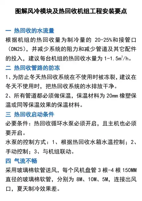
图解风冷模块及热回收机组工程安装要点一热回收的水流量根据机组的热回收量为制冷量的20-25%和接管口(DN25),并减少系统的阻力和减少管道及其它配件的投入,建议每台机组的热回收水量为1-1.5m3/h。
二热回收管路的防冻1、为防止冬天热回收系统在不使用时被冻裂,建议在冬天不使用时,把热回收系统的水排放干净。
2、所有管道都必须做保温,保温材料为20mm橡塑保温或同等保温效果的保温材料。
三热回收启动条件必要条件:热回收循环水泵必须开启,且主机也必须要开启。
水泵的控制方式:1、根据热回收水箱水温控制;2、手动控制;3、与机组联动。
四气流不畅采用玻璃棉软管送风,每个风机盘管3根-4根150MM 直径的玻璃棉软管,分别为8M、10M、5M,连接出风口,夏天制冷效果差。
5M风管出风量较大、8M、10M风管出风量很小室内效果很差,内机窝风严重。
将风管直径改大为200MM-250MM;将风管长度减至6m 以内故障排除。
五气流短路室内:空调的送风口离空调的回风口太近(一般在1.5米以上),或离室内排风口太近(一般在1.5米以上)。
六冬天效果不好夏天制冷效果好冬天制热效果差,冬天时室内天花板与工作台温差>7℃。
原设计:1、采用侧送顶回的送回风方式,送风口采用格栅风口;2、采用顶送顶回的送回风方式,送风口采用方形散流器。
整改后:充一采用可调百叶送风口,效果较好。
七冷凝水排不出空调箱外:1、工程(图A)存在以下现象:空调箱蒸发器集水盘的水不能排出,流到风机段使电机受潮或泡坏电机;停机时水从空调箱流出地面(说明)。
工程冷凝水管没有按机型标准制作。
2、对策:按图B制作冷凝水管:其中公式内长度单位为:MML=X+H+(1.5*排水管直径) X=2H H=25.4*(1+机组静压/249)。
排水管保应保持坡度,管路过长时在回水弯后装置排气口。
八超出机组工作范围:模块机组属于商用中央空调机组,在夏天时运行制冷模式,冬天运行制热模式,但有些商家用做其他用途,如工业冷水机组(全年运行制冷)从而引起以下后果:1、机组不正常运行(如;低压过低);2、机组寿命缩短。

通用水冷模块机控制器安装使用手册程序编码: MD24 2015-12-14请务必仔细阅读此手册内容,并按照说明操作!如有疑问,请联系:广州得麦电子科技有限公司网址:邮箱:gzdaimc@(未经允许以任何形式或手段复制或传播本手册内容均属侵权,必究法律责任。
)目录一、安全使用 (3)二、产品简介 (4)2.1 SK系列真彩触摸屏显示器 (4)2.2 ZY101控制板性能指标 (4)三、安装指南 (5)3.1 4.3寸真彩触摸屏显示器SK043外型尺寸 (5)3.2 主控板ZY101外型尺寸 (5)四、主界面说明 (5)4.1开机界面 (6)4.2主界面 (6)4.3用户设置界面 (7)4.4输入查询界面 (7)4.5输出查询界面 (8)4.6故障查询界面 (9)4.7软件版本界面 (9)五、参数设置 (10)5.1厂家参数设置进入方式 (10)5.2维修参数设置进入方式 (11)5.3温度设置 (12)5.4时间设置 (12)5.5防冻设置 (13)5.6开关量定义 (13)5.7厂家参数 (14)5.8参数初始化 (14)5.9修改密码 (14)5.10维护时间设置 (15)六、控制逻辑 (17)6.1.1开机逻辑 (17)6.1.2关机逻辑 (17)6.1.3线控开关 (17)6.1.4冷却塔风机 (17)七、通讯接线示意图 (18)八、水冷模块机机电气连接示意图 (19)九、版本说明 (21)一、安全使用提示:危险!会引起人身伤亡和财产损失的不正确操作与安装。
警告!会引起人身伤害和财产损失的不正确操作与安装。
注意!会影响控制器性能的不正确操作。
二、产品简介水冷柜机控制器采用分体安装,由SK系列真彩触摸屏显示器和ZY101控制板两部分组成。
显示器采用400MHZ ARM9处理器,支持4.3寸,7寸、10寸不同大小真彩屏,可满足几乎所有工业现场应用需求。
ZY101控制板是专门为暖通或中央空调行业应用定制的。
![[电子电路]南京天加空调模块机组安装操作手册_R22PDF2012-9-21](https://uimg.taocdn.com/6207bf695bcfa1c7aa00b52acfc789eb172d9e31.webp)
MODULAR AIR-COOLED CHILLER (HEAT PUMP)目录一、安全注意事项--------------------------------------------------------------2二、适用范围及特点-----------------------------------------------------------3三、产品及主要部件介绍-----------------------------------------------------4四、型号说明、技术参数及外形尺寸---------------------------------------51、型号说明----------------------------------------------------------------52、外形尺寸----------------------------------------------------------------5五、安装与调试-----------------------------------------------------------------61、安装基础图-----------------------------------------------------------62、机组的安装-----------------------------------------------------------73、水系统的安装---------------------------------------------------------84、电气安装-------------------------------------------------------------145、开机调试------------------------------------------------------------27六、维护保养----------------------------------------------------------------28七、故障分析与维修--------------------------------------------------------29八、售后服务------------------------------------------------------------------30九、配件的安装说明--------------------------------------------------------31对于不同系列型号的机组,冷媒冲注量不一样,必须依据铭牌为准,按照说明书正确操作维护!1MODULAR AIR-COOLED CHILLER (HEAT PUMP)二.适用范围及特点适用范围模块化风冷式冷(热)水机组创新性运用了模块化设计方案,使该系列机组在具有普通整体风冷冷(热)水机组特点的同时,还兼备应用灵活、安装方便的特点,包含从TCA201到TCA312多种冷量,C、D、N、F多个系列上百个规格供选择。
风冷模块机组安装1)开箱检验:开箱应在施工、监理、业主三方均有人参加时进行。
对照图纸及设备表中所提供的型号、数量、核对每一台机组应有的制造铭牌、型号、性能参数、生产厂家和日期、编号,并查验随机资料(如合格证,安装使用说明书、保修信用卡等)。
2)风冷模块机组设在楼顶,单台体积大,重量大,在设备安装前须仔细检查基础是否完好,槽钢基础尺寸和机组匹配,才可安装设备,基础表面的平整度、位置、尺寸、标高是否符合要求.3)风冷模块机组运输到位后,检查机组有无泄漏,油封是否完好。
4)设备就位后,应按设备技术文件规定的基准面找正水平,其纵向、横向水平度不应超过规范要求。
5)按随机的文件说明安装减震装置。
各组减震器承受荷载的压缩量应均匀,不得偏心,安减震器的地面应平整,机组水平度应在减震器上加垫片调整,不可用调整弹簧压缩量进行调整.水平度及坡向应符合规范或随机文件的规定。
减震器安装后,在其使用前应采取保护措施,以防损坏。
6)风冷模块机组放好后,用水准仪检查其纵横向安装水平偏差,均不应大于规范要求,并应在曲轴的外露部位、底座或与底座平行的加工面。
3。
2。
3、循环水泵安装1)水泵到场后,组织甲方、监理、供货厂家的代表联合开箱检查,并填写设备开箱检验报告单,具体步骤如下:A、进货严格对照图纸及设备表中所提供的型号、数量、核对每一台水泵应有的制造铭牌、型号、性能参数、生产厂家和日期、编号,并查验随机资料(如合格证,安装使用说明书、保修信用卡等)。
B、根据装箱清单及有关图纸、说明书查看外形有无损伤、缺陷、叶轮、轴、外壳是否变形,油漆是否脱落,表面有无锈蚀等,核查进、出口方位尺寸,叶轮和旋转方向应符合设计文件之规定。
C、清点散装的零部件、配件和备件,并将整机上易丢失、损坏的零部件拆卸涂上油脂进行包装、编号,按质量控制程序,一并入库妥善保管、条件具备时再进行安装。
3)水泵搬运和吊装水泵主要安装在泵房内,根据设备重量及到货情况选用具体的吊装搬运方案,重量较轻的可直接采用叉车运输、就位;重量较重的,也可采用滚杠拖排法运输就位。
一.作业场地布置要求及前期准备加工场地现场应有空旷的成品堆放地,便于运输,场地道路应畅通,通风良好,并应设置必要的消防器材,场地保持清洁,文明施工。
安装现场应整洁,材料保管妥善,人员分工明确。
管道、附件和设备安装前,必须清除污垢杂物。
施工中断或完成时的敞口处,应临时封堵,严谨将工具、物件放置管内。
给水系统在使用前,应用水冲洗干净.在施工过程中,与其他工种的配合应及时,加强互相协作,注意保护建筑成品,并及时填写各项施工验收技术材料。
(1).风冷模块安装前期准备工作:1、机组运到安装现场,应仔细检查,对照装箱单检查所有项目,如发现机组损坏,缺少零部件,或运输过程中造成损坏,应通知销售部。
2、用户需提供不变形的刚性基础或混凝土底座,基础尺寸的大小参照机组四肢定位孔尺寸,机组的基础也可采用框架式结构,框架安放于承重梁或承重柱上,并保证框架具有承载超出机组本身重量130%的能力和基础的平整度。
、3、位便于搬运,用户应使用叉车或吊车。
使用吊车时,应当有合适的隔离物来保护机组顶部和侧面板。
搬运过程中,机组应保持水平状态,避免因鲁莽操作而损坏机组。
4、安装位置选择。
风冷模块机组可安装在户外地面、屋顶或其他合适的位置。
同事应考虑以下因素:排气阀门必须设在水系统的最高点。
在水系统最低点安装合适的排水塞或阀门。
水管必须保温,以防止热量散失和冷凝水形成。
系统管道的安装连接要根据国家和当地暖通规范进行。
机组和水泵连入系统要用避震软接头,同时管道及水泵要自设支架,以免机组受力。
严谨在未冲净管路时就打开机组进出口截止阀。
二.模块机组安装要求及规范(1).模块机组吊装、安装注意事项:1.机组在搬运移动时应尽量保持水平,切勿倾斜30度以上,吊具上部应有支撑杆,以免伤及设备;2.机组可安装于屋顶或室外庭院,且支撑面须有足够的强度,能承受机组运行时的重量;3.机组不应安装在灰尘大、污物多、有腐蚀性气体和湿度大的场合;4.机组安装场合须留有足够的空间(前后左右各1.5米以上)以供散热和方便维修人员进出;5.机组就位时,应将防震软垫放于机组底框下,调整机组成水平后方可紧固底脚螺栓;6.机组应尽量避免日晒、雨淋,建议加盖防雨防晒棚,但应保证出风口上方有3米以上的空间,以利空气的流通;7.空调系统水管路安装、保温,应由专业人员设计指导、并执行暖通空调安装规范的相应规定:8.外部水管路系统必须安装防震软接头、过滤器、电子除垢仪、止逆阀、排水阀、排气阀、截止阀、膨胀水箱;膨胀水箱应安装在高于系统最高处1—1.5米:水箱容量约为整个系统水量的1/10;排气阀应安装在系统最高处与膨胀水箱之间;(2).风冷热泵机组必须安装在通风散热良好的场所。
C目录一、 安全注意事项 --------------------------------------------------------------2二、 适用范围及特点 -----------------------------------------------------------3三、 产品及主要部件介绍 -----------------------------------------------------4四、 型号说明、技术参数及外形尺寸 ---------------------------------------51、 型号说明 ---------------------------------------------------------------52、 技术参数及外形尺寸---------------------------------------------5五、 安装与调试 ----------------------------------------------------------------141、 安装基础图 ----------------------------------------------------------142、 机组的安装 ----------------------------------------------------------143、 水系统的安装 --------------------------------------------------------164、 电气安装 -------------------------------------------------------------215、 开机调试 ------------------------------------------------------------27六、 维护保养 ----------------------------------------------------------------28七、 故障分析与维修 --------------------------------------------------------29八、 售后服务 ------------------------------------------------------------------30九、 配件的安装说明 --------------------------------------------------------31十、 常年制冷机组说明--------------------------------------------------------35对于不同系列型号的机组,冷媒种类与冲注量可能不一样,必须依据铭牌为准,按照说明书正确操作维护!F 系列性能参数表型号TCA 201FH 202FH 203FH 204FH 205FH 206FH 207FH 208FH 209FH 210FH 211FH 212FH 名义制冷量 kW 66 132 198 264330396462 528 594 660 726 792名义制热量 kW 75 150 225 300375450525 600 675 750 825 900电源380V/3N~/50Hz 类型 高效率板式换热器水流量 m3/h 11.4 22.8 34.1 45.556.968.379.791.0102.4 113.8 125.2136.6水压降 KPa 96 103 109 115120125130 135 140 145 150 155蒸发器 进出水管径 DN DN40内螺纹活结运行方式 全自动微电脑控制运行或手动运行类型 全封闭涡旋式压缩机 额定功率(kW) 21 42 63 84 105126147 168 189 210 231 252压缩机 数量 台 2 4 6 8 10 12 14 16 18 20 22 24类型 轴流低噪音大叶轮风量 m3/h 24000 48000 72000 96000120000144000168000192000216000 240000 264000288000数量 台 24 6 8 10 12 14 16 18 20 22 24 风机 输入功率 k W 1.5 3.04.56.07.59.010.5 12.013.515.0 16.518.0类型 R22制冷剂 充注量 kg 18 36547290 108126144 162180198216长 mm 2206 宽 mm 1030 2060 3090 412051506180721082409270 10300 1133012360外形尺寸 高mm 2063机组重量 kg 740 1480 2220 296037004440518059206660 7400 81408880机组运行重量 kg 7991598 2397 319739964795559463937193 7992 87919590可选辅助电加热kW 151825273236404550546372备注:1、 名义制冷运行工况:进水温度12℃,出水温度7℃,室外温度35℃2、 名义制热运行工况:进水温度40℃,出水温度45℃,室外温度7℃3、 在实际使用中冷热量应考虑机组安装后系统管路、水泵、阀门、污垢等损失6%左右4、 规格参数如因产品改良而更改,恕不另行通知5、 机组每个模块的进出水管管径都是DN40,预留内螺纹活接软连接。
THIS PRODUCT CONTAINS ELECTRONIC COMPONENTS WHICH RE-QUIRE A DEFINITE GROUND. PROVISIONS ARE MADE FOR CONNEC-TION OF THE GROUND. A DEDICATED GROUND FROM THE MAIN POWER SUPPLY OR AN EARTH GROUND MUST BE PROVIDED.INTRODUCTIONThis booklet contains the installation and operating instructions for your modular blower cabinet. All warnings and precautions within this booklet must be observed. Improper installation can result in problems ranging from noisy operation to property or equipment damages, dangerous conditions that could result in injury or personal property damage and that are not covered by the warranty. Read this booklet and any instructions packaged with accessories prior to installation. Give this booklet to the user and explain its provisions. The user should retain this booklet for future reference.MBR BLOWER CABINETINSTALLATION INSTRUCTIONS © 2013-2015, 2017 Goodman Manufacturing Company, L.P.5151 San Felipe, Suite 500, Houston, TX -or- P/N: IO-448C Date: December 2017CHECKING PRODUCT RECEIVEDUpon receiving the unit, inspect it for damage from shipment.Claims for damage, either shipping or concealed, should be filed immediately with the shipping company. Check the unit model number, specifications, electrical characteristics and accesso-ries to determine if they are correct. In the event an incorrect unit is shipped, it must be returned to the supplier and must NOT be installed. The manufacturer assumes no responsibility for in-stallation of incorrectly shipped units.REPLACEMENT PARTSORDERING PARTSWhen reporting shortages or damages, or ordering repair parts,give the complete unit model and serial numbers as stamped on the unit’s nameplate.Replacement parts for this appliance are available through your contractor or local distributor. For the location of your nearest distributor, consult the white business pages, the yellow page section of the local telephone book or contact:HOMEOWNER SUPPORTGOODMAN MANUFACTURING COMPANY, L.P.19001 KERMIER ROAD WALLER, TX 77484(877) 254-4729ContentsI NTRODUCTION .....................................................................1C HECKING P RODUCT R ECEIVED ...................................................1R EPLACEMENT P ARTS . (1)Ordering Parts (1)I MPORTANT S AFETY I NSTRUCTIONS (2)Recognize Safety Symbols, Words, and Labels (2)General Information (2)Clearances and Accessibility ...........................................................2Insulation . (3)Installation Instructions (3)Blower with Cased Evaporator Coil Installation.................................3Upflow Installation .........................................................................3Counterflow Installation..................................................................3Horizontal installation (3)Electrical Connections (4)High Voltage Wiring........................................................................4Low Voltage Wiring.........................................................................4Foam Tape Strip ..............................................................................4Miscellaneous Electrical..................................................................5Thermostat Connections (5)IMPORTANT SAFETY INSTRUCTIONSRECOGNIZE SAFETY SYMBOLS, WORDS, AND LABELSThe following symbols and labels are used throughout this manual to indicate immediate or potential hazards. It is the owner’s responsibility to read and comply with all safety information and instructions accompanying these symbols. Failure to heed safety information increases the risk of property damage, product damage, personal injury or death.GENERAL INFORMATIONThe MBR Blower Cabinets are used in combination with a cased evaporator coil. This combination of blower and coil functions as the indoor part of a split air-conditioning system, and may be matched with a remote condensing or heat pump unit. The blower cabinet can also function as an electric furnace when used with an electric heater.NOTE: The electric heating elements for electric furnace installation are not shipped with the cabinet and are field-installed. Systems should be properly sized by heat gain and loss calculations made according to methods of the Air Conditioning Contractors Association (ACCA) or equivalent. It is the contractor’s responsibility to ensure the system has adequate capacity to heat or cool the conditioned space.CLEARANCES AND ACCESSIBILITYThe unit can be positioned for upflow, counterflow, horizontal right or horizontal left operation. Zero clearance is allowed on all sides for combustible materials. Thirty-six inches should be allotted on the door side for maintenance and service.To reduce risk of rusting, do not install the unit blower directly on the ground or on a floor that is likely to be wet. In such environments, the unit must be elevated by use of a sturdy, nonporous material.•Cabinet air leakage less than 2.0% at 1.0 inch H2O when tested in accordance with ASHRAE standard 193.•Cabinet air leakage less than 1.4% at 0.5 inch H2O when tested in accordance with ASHRAE standard 193.A CHIEVING L ESS A IR L EAKAGE :Ensure all the gaskets remain intact on surfaces as shipped with the unit. Ensure upon installation that the plastic breaker cover is flush on with the access panel and access panel is flush with the cabinet. With these requirements satisfied, the unit achieves less airflow leakage when tested in accordance with ASHRE Standard 193.INSULATIONTo ensure efficient operation, review the following precautions.•If the unit is located in an area with high ambient temperature and/or high humidity, the air handler may be subject to nuisance sweating of the casing. On these installations, a wrap of 2” fiberglass insulation with a vapor barrier is recommended.•The factory recommends insulating the duct running through any unconditioned spaces.To reduce operating sound and vibration transmission use flexible canvas duct connec-tions at the cabinet.INSTALLATION INSTRUCTIONSBLOWER WITH CASED EVAPORATOR COIL INSTALLATIONSecure the coil and blower together with the two connector plates and screws supplied in the blower bag assembly. Use one connector plate and six screws on each side of the unit (Figure 1).If accessory electric heat is to be added, install now per the instructions shipped with the heater kit.UPFLOW INSTALLATIONFor upflow installations, the blower cabinet must sit on top of the coil cabinet (Figure 2).NOTE: All panels should be in place before installing the cabinet.1.Place the blower and coil cabinet assembly upright on the return duct or duct opening.Ensure that there is ample support for the cabinet assembly and all attached ductwork.2.Connect refrigerant and condensate drain connections per the evaporator coil installation instructions. Ensure refrigerant and drain lines do not interfere with service access to the unit.3.Attach supply ductwork. Seal connections between unit and ductwork as required to reduce/eliminate air leakage.4.Make electrical connections as specified in “Electrical” section of this manual.COUNTERFLOW INSTALLATIONFor counterflow installations, the evaporator coil cabinet must sit on top of the blower cabinet (Figure 3). NOTE: All panels should be in place when installing the unit.NOTE: Supply ductwork for counterflow applications, must be Class I. However, if combus-tible ductwork is used, sheet metal protection is required.1.Place the blower and coil cabinet assembly supply outlet on the supply duct or duct opening. Ensure there is ample support for the unit and all attached ductwork.2.Connect refrigerant and condensate drain connections per the evaporator coil installation instructions. Ensure refrigerant and drain lines do not interfere with service access to the unit.3.Attach return ductwork. Seal connections between unit and ductwork as required to reduce/eliminate air leakage.4.Make electrical connections as specified in “Electrical” section of this manual.HORIZONTAL INSTALLATIONFor horizontal installations, the coil cabinet must be upstream of the blower cabinet (Figures 4 and 5). NOTE: All panels should be in place when installing the unit.TOP CABINETBOTTOM CABINETFigure 1 - Coil and BlowerFigure 2 - Upflow ApplicationFigure 3 - Counterflow ApplicationAir FlowBlower CabinetSupport1.Set the unit near its final installation place. The unit must be supported along the entire length of the unit. Rubber isolation pads may be used to reduce sound and vibration transmission. Ensure there is ample support for the unit and all attached ductwork.2.If installed above a finished ceiling or living space, be sure to put a secondary drain pan under the entire unit, and pipe the drain separately from the main condensate drain.3.Connect refrigerant and condensate drain connections per the coil section installa-tion instructions. Ensure refrigerant and drain lines do not interfere with service access to the unit.4.Attach return and supply ductwork. Seal connections.5.Make electrical connections as specified in “Electrical” sec-tion of this manual.ELECTRICAL CONNECTIONSConsult the local power company and local codes before install-ing this unit. All wiring must be in accordance with the National Electrical Code as well as all local codes. Knockouts have been provided on side and top of the cabinet for the installation of the electrical conduit. If the knockouts on the cabinet sides are used for electrical conduit, an adapter ring must be used in order to meet UL1995 safety requirements. Use Minimum Circuit Ampacity and type of wire to determine proper wire size. The unit MUST be properly grounded. A ground lug is provided in the unit.Check all factory connections before connecting electrical power to unit to ensure none were loosened or disconnected during ship-ping and handling.HIGH VOLTAGE WIRINGIf heater kits will not be installed, remove the proper size knockout for the electrical conduit connection. Connect electrical conduit to the unit using two washers to make an approved connection. If the high voltage knockout is removed, please use the provided foam tape to seal the opening with the conduit.The power supply wires must be connected to the red and black power wiring. Two wire nuts are provided in the bag assembly for this connection. Wrap the wire nuts with electrical tape. (Insulated crimp type connectors, field supplied, may be substituted for the wire nuts and electrical tape provided proper size connectors are used.) A ground wire MUST be connected to the ground lug inside the unit.LOW VOLTAGE WIRINGA 24V-control voltage connects the air handler to the room thermostat and condenser and must use low voltage wiring with copper conductors. A minimum 18 AWG wire must be used for installations up to 100 feet. Low voltage wiring must be connected through the top of the cabinet or either side. See the “Thermostat Wiring” section of this manual for typical low voltage wiring connections. If the low voltage opening is not being used, install the cap, provided in the literature kit, on the top plate.Figure 5 - Hanging InstallationFOAM TAPE STRIPNOTE: In high humidity areas, it is highly recommended to install this component in order to reduce the amount of “sweating”.For MBR1200 ONLY, use one of the foam strips provided in the literature kit:e one of the provided foam tape strips to seal the hole in the control panel. In order to use the foam tape, carefully remove theadhesive liner and wrap the tape around the wires at the control panel. Ensure the tape is sealed onto both the sheet metal of the control panel and the wires with convenient connections to outdoor thermostat applications.Each diagram details the connections between room thermostat and MB air handlers, and the connections between the MB air handlers and the Condensing Unit (or Heat Pump) with optional connections to Outdoor Thermostats.MISCELLANEOUS ELECTRICALThe unit transformer is factory connected for 240 V operation. If unit is to operate on 208 V, disconnect the red wires from terminal 3 of the unit transformer and connect them to terminal 2 of the unit transformer.INSTALLER: It is important to follow these instructions when installing the MB series of air handlers.THERMOSTAT CONNECTIONSThe following composite wiring diagrams detail various configurations in which your MB air handler can be used. Examples include single stage cooling, two stage cooling and heat pump with single or two stage electric heating. All these configurations can be applied with convenient connections to outdoor thermostat applications.Each diagram details the connections between room thermostat and MB air handlers, and the connections between the MB air handlers and the Condensing Unit (or Heat Pump) with optional connections to Outdoor Thermostats.THIS PAGE LEFT INTENTIONALLY BLANKROOM THERMOSTAT WYGR#18 GA. 4 WIRES WITHCOOLING 3 WIRES WITHOUTR GW YTO CONDENSINGUNIT 24V. CONNECTIONS #18 GA. 2 WIRESBLUEWHITEGREENRED CONTACTOR COILMBR UNITW2W Y G RR GYWGREEN RED WHITE BLUEBROWN #18 GA. 4 WIRE WITHCOOLING 3 WIRE WITHOUTROOM THERMOSTATOUTDOOR THERMOSTAT (OPTIONAL)CONDENSINGUNIT 24V. CONNECTIONS #18 GA. 2 WIRES#18 GA. 2 WIRESCONTACTOR COILMBR UNITFigure 6 - Low Voltage Wiring Diagram for Cooling Unit with optional heat kit 10KW and belowFigure 7 - Low Voltage Wiring Diagram for Cooling Unit with optional heat kit 15KW and above0140A00245-ATHIS PAGE LEFT INTENTIONALLY BLANKTHIS PAGE LEFT INTENTIONALLY BLANKCUSTOMER FEEDBACKWe are very interested in all product comments.Please fill out the feedback form on one of the following links:Daikin Products: (https:///contact-us)Goodman® Brand Products:(/about/contact-us).Amana® Brand Products: (/about-us/contact-us).You can also scan the QR code on the right for the product brand you purchasedto be directed to the feedback page.PRODUCT REGISTRATIONThank you for your recent purchase. Though not required to get the protection ofthe standard warranty, registering your product is a relatively short process, andentitles you to additional warranty protection, except that failure by Californiaand Quebec residents to register their product does not diminish their warrantyrights.For Product Registration, please register as follows:Daikin Products: (https:///owner-support/product-registration).Goodman® Brand products: (https:///product-registration).Amana® Brand products: (/product-registration).You can also scan the QR code on the right for the product brand you purchasedto be directed to the Product Registration page.DAIKIN GOODMAN® BRAND AMANA® BRAND AMANA® BRANDGOODMAN® BRAND DAIKIN。
®风冷式冷水(热泵)机组安装应用说明书机型:HLR100/M6HL100/M6安装使用本机组之前,请仔细阅读说明书,并妥善保存以备日后参考四川长虹电器股份有限公司特别提醒1、产品为风冷式冷水(热泵)机组,主要用于空调系统,请勿用于其他用途。
2、请勿自行安装。
本产品只有正确安装在合理的空调系统中才能可靠地运行,错误的安装将可能导致机组运转不正常、机组损坏、人身伤害或财产损失。
3、系统中的循环水量应进行准确的设计,防止由此引起的制冷(热)速度太慢或温度波动太大。
0℃时,对循环水系统设计必须进行防冻结处理。
如果释放干净。
冬季因循环水冻结造成机组损坏,制造商不承担任何责任。
1、锋利的棱边和换热器表面都具有伤害性,应避免接触。
2、移动机组或电源是危险的,它足以引起人受伤或死亡。
3、在维修、移动、安装机组前必须切断电源,否则会触电。
4、切勿拆除机组风叶网罩,切勿用手或其它物品伸进机组进出风口,否则会造成人身伤害或机组损坏。
5、切勿向机组淋水及湿手操作机组,否则会造成故障或发生触电危险。
6、机组上切勿站人或放置物品,否则人或物品会掉下来。
7、切勿使用容量不相符的漏电断路器,切勿用导线或铁丝代替漏电断路器,否则会造成故障或引起火灾。
本说明书所用图示均为示意图,产品请以实物为准!本说明书包括长虹现在生产的产品,若设计或产品结构变化时,恕不另行通知!欢迎您加入长虹电器用户的行列,在安装使用本机组之前,请仔细阅读说明书。
目录1 重要参数 (1)2 工况条件 (1)3 产品规格 (2)4 用户使用说明 (2)5 外形尺寸 (3)6 安装附件 (3)7 安装须知 (3)8 系统设计注意事项 (3)9 安装位置选择 (4)10 安装基础与安装要求 (5)11 机组搬运注意事项 (5)12 进出水管连接 (6)13 电气配线 (6)14 机组试运行 (7)15 维护保养说明 (7)16 机组试运转参数 (9)1 重要参数1.1稳定工作范围电源:3N~,342~418V,50Hz。