填料塔计算表scrubber_design
- 格式:xls
- 大小:694.00 KB
- 文档页数:58
二 基础物性参数的确定1 液相物性数据对于低浓度吸收过程,溶液的物性数据可近似取纯水的物性数据。
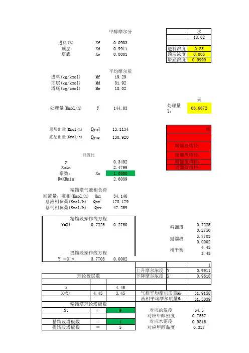
由手册查得,2 气相物性参数设计压力:101.3kPa ,温度:20C ︒氨气在水中的扩散系数:92621.7610/ 6.33610/L D cm s m h --=⨯=⨯ 氨气在空气中的扩散系数:查表得,氨气在0°C ,101.3kPa 在空气中的扩散系数为0.17 2/cm s , 根据关系式换算出20C ︒时的空气中的扩散系数:332200022293.150.171273.150.189/0.06804/VP T D D P T cm s m h ⎛⎫⎛⎫⎛⎫==⨯⨯ ⎪ ⎪ ⎪⎝⎭⎝⎭⎝⎭==混合气体的平均摩尔质量为m i 0.05170.982929.27V i M y M ==⨯+⨯=∑混合气体的平均密度为3m 101.329.27 1.2178.314293.15V Vm PM kg m RT ρ⨯===⨯混合气体的粘度可近似取空气的粘度,查手册得20C ︒空气粘度为51.81100.065()V Pa s kg m h μ-=⨯•=•3 气液相平衡数据由手册查得,常压下20C ︒时,氨气在水中的亨利系数76.3a E kP =相平衡常数76.30.7532101.3E m P ===溶解度系数3s998.20.726076.318.02LH kmol kPa m EM ρ===•⨯4 物料衡算进塔气相摩尔比1=110.050.05263110.05y Y y ==-- 出塔气相摩尔比321(1)0.05263(10.98) 1.05310A Y Y ϕ-=-=-=⨯混合气体流量330.1013(273.1520)16.10100.1013273.15V N Q Q m h ⨯⨯+==⨯⨯惰性气体摩尔流量273.15(10.05)636.1622.4273.1520V Q V kmol h =⨯-=+该吸收过程属低浓度吸收,平衡关系为直线,最小液气比可按下式计算:1212L Y Y V Y m X -⎛⎫= ⎪-⎝⎭对于纯溶剂吸收过程,进塔液相组成 20X =min0.052630.0010530.73810.052630.7532L V -⎛⎫== ⎪⎝⎭ 取操作液气比为 min1.4L L V V ⎛⎫= ⎪⎝⎭1.40.7381 1.0333LV=⨯= 1.0333636.16657.34L kmol h =⨯=1212()636.16(0.052630.001053)0.0499657.34V Y Y X X L -⨯-=+==表2-4-15 吸收塔的工艺尺寸计算5.1 塔径计算采用Eckert 通用关联图计算泛点气速。
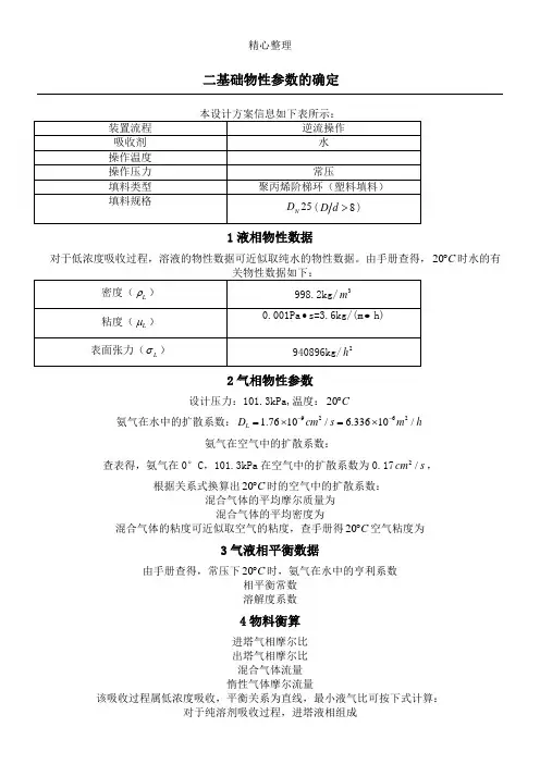
二基础物性参数的确定由手册查得,常压下20C︒时,氨气在水中的亨利系数相平衡常数溶解度系数4物料衡算进塔气相摩尔比出塔气相摩尔比混合气体流量惰性气体摩尔流量该吸收过程属低浓度吸收,平衡关系为直线,最小液气比可按下式计算:对于纯溶剂吸收过程,进塔液相组成取操作液气比为Eckert 通用关联图:气体质量流量为液体质量流量可近似按纯水的流量计算:Eckert 通用关联图的横坐标为根据关联图对应坐标可得由表2-4-1可知F φ=2601m -取0.80.8 2.360 1.888/F u u m s ==⨯=由 1.737D===m圆整塔径(常用的标准塔径有400mm、500mm、600mm、800mm、1000mm、1200mm、1400mm、1600mm、2000mm、2200mm等)本设计方案取D=2000mm。
泛点率校核:因为填料塔的适宜空塔气速一般取泛点气速的50%-80%,泛点率值在允许范围内。
填料塔规格校核:200080825Dd==>(在允许范围之内)液体喷淋密度校核:maxD取8hD=,则计算得填料层高度为4000mm,故不需分段5.3填料层压降计算采用Eckert通用关联图计算横坐标为由表2-4-1得,1176Pmφ-=纵坐标为查Eckert通用关联图,P∆/Z位于40g~50gPa/m范围内,取P∆/Z=45g=441.45Pa/m填料层压降为∆=441.45⨯4.0=1765.80PaP6液体分布器的简要设计6.1液体分布器的选型本设计的吸收塔气液相负荷相差不大,无固体悬浮物和液体粘度不大,加上设计建议是优先选用槽盘式分布器,所以本设计选用槽盘式分布器。
6.2分布点密度计算按Eckert建议值,1200m,由于该塔喷淋密度较小,设计区分喷淋D≥时,喷淋点密度为42点/2点密度为90点/2m。
槽宽度为。
填料吸收塔设计任务书一、设计题目填料吸收塔设计二、设计任务及操作条件1、原料气处理量:5000m3/h。
2、原料气组成:98%空气+2.5%的氨气。
3、操作温度:20℃。
4、氢氟酸回收率:98%。
5、操作压强:常压。
6、吸收剂:清水。
7、填料选择:拉西环。
三、设计内容1.设计方案的确定及流程说明。
2.填料吸收塔的塔径,填料层的高度,填料层的压降的计算。
3.填料吸收塔的附属机构及辅助设备的选型与设计计算。
4.吸收塔的工艺流程图。
5.填料吸收塔的工艺条件图。
目录第一章设计方案的简介 (4)第一节塔设备的选型 (4)第二节填料吸收塔方案的确定 (6)第三节吸收剂的选择 (6)第四节操作温度与压力的确定 (7)第二章填料的类型与选择 (7)第一节填料的类型 (7)第二节填料的选择 (9)第三章填料塔工艺尺寸 (10)第一节基础物性数据 (10)第二节物料衡算 (11)第三节填料塔的工艺尺寸的计算 (12)第四节填料层压降的计算 (16)第四章辅助设备的设计与计算 (16)第一节液体分布器的简要设计 (16)第二节支承板的选用 (17)第三节管子、泵及风机的选用 (18)第五章塔体附件设计 (20)第一节塔的支座 (20)第二节其他附件 (20)第一章设计方案的简介第一节塔设备的选型塔设备是化工、石油化工、生物化工制药等生产过程中广泛采用的气液传质设备。
根据塔内气液接触构件的结构形式,可分为板式塔和填料塔两大类。
1、板式塔板式塔为逐级接触式气液传质设备,是最常用的气液传质设备之一。
传质机理如下所述:塔内液体依靠重力作用,由上层塔板的降液管流到下层塔板的受液盘,然后横向流过塔板,从另一侧的降液管流至下一层塔板。
溢流堰的作用是使塔板上保持一定厚度的液层。
气体则在压力差的推动下,自下而上穿过各层塔板的气体通道(泡罩、筛孔或浮阀等),分散成小股气流,鼓泡通过各层塔板的液层。
在塔板上,气液两相密切接触,进行热量和质量的交换。
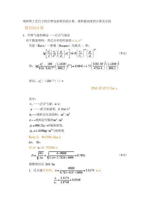
填料塔工艺尺寸的计算包括塔径的计算、填料能高度的计算及分段塔径的计算1. 空塔气速的确定——泛点气速法 对于散装填料,其泛点率的经验值u/u f =~贝恩(Bain )—霍根(Hougen )关联式 ,即:2213lg V F L L u a gρμερ⎡⎤⎛⎫⎛⎫⎢⎥⎪ ⎪⎝⎭⎝⎭⎣⎦=A-K 1418V L V L w w ρρ⎛⎫⎛⎫ ⎪ ⎪⎝⎭⎝⎭ (3-1) 即:112480.23100 1.18363202.59 1.1836lg[()1]0.0942 1.759.810.917998.24734.4998.2Fu ⎛⎫⎛⎫⎛⎫=- ⎪ ⎪ ⎪⎝⎭⎝⎭⎝⎭所以:2F u /(100/3)()=UF=3.974574742m/s其中:f u ——泛点气速,m/s;g ——重力加速度,9.81m/s 2 23t m /m α--填料总比表面积,33m /m ε--填料层空隙率33V 998.2/1.1836kg /m l kg m ρρ==液相密度。
气相密度W L =㎏/h W V =7056.6kg/h A=; K=;取u= F u =2.78220m/s0.7631D === (3-2)圆整塔径后 D=0.8m 1. 泛点速率校核:260003.31740.7850.83600u ==⨯⨯ m/s3.31740.83463.9746F u u ==则Fuu 在允许范围内 2. 根据填料规格校核:D/d=800/50=16根据表3-1符合 3. 液体喷淋密度的校核:(1) 填料塔的液体喷淋密度是指单位时间、单位塔截面上液体的喷淋量。
(2) 最小润湿速率是指在塔的截面上,单位长度的填料周边的最小液体体积流量。
对于直径不超过75mm 的散装填料,可取最小润湿速率()3min 0.08m /m h w L ⋅为。
()32min min 0.081008/w t U L m m h α==⨯=⋅ (3-3)225358.895710.6858min 0.75998.20.7850.8L L w U D ρ===>=⨯⨯⨯⨯ (3-4) 经过以上校验,填料塔直径设计为D=800mm 合理。
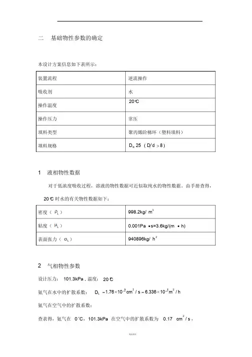
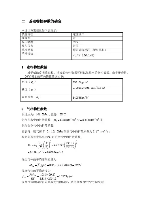
2装置流程 逆流操作 吸收剂操作温度 水 20 C操作压力 常压填料类型 聚丙烯阶梯环(塑料填料)填料规格D N 25 ( D d 8 )1 液相物性数据对于低浓度吸收过程,溶液的物性数据可近似取纯水的物性数据。
由手册查得, 20 C 时水的有关物性数据如下: 密度( L) 998.2kg/ m3粘度(L)0.001Pa s=3.6kg/(mh)表面张力(L)940896kg/ h22 气相物性参数设计压力: 101.3kPa , 温度: 20 C 氨气在水中的扩散系数: D L1.76 10 cm / s 9 2 6.336 10 m / h6 2二 基础物性参数的确定本设计方案信息如下表所示:氨气在空气中的扩散系数:查表得,氨气在 0°C ,101.3kPa 在空气中的扩散系数为 0.17cm / s ,2根据关系式换算出 20 C 时的空气中的扩散系数:3 3P 0 D VD 0T 0.17 1293.15 2PT 0273.150.189cm 2/ s 0.06804m 2/ h混合气体的平均摩尔质量为M Vmy i M i 0.05 17 0.98 29 29.27混合气体的平均密度为PM Vm101.3 29.27 1.217kg m3VmRT 8.314 293.15混合气体的粘度可近似取空气的粘度,查手册得20 C 空气粘度为1. 8 1 150P a s0. 0k6g5 m ( h)3 气液相平衡数据由手册查得,常压下 20 C 时,氨气在水中的亨利系数E 相平衡常数76.3kPamEP 溶解度系数H76.30.7532101.3L998.2 0.7260 kmol kPa m3EM s76.3 18.024 物料衡算进塔气相摩尔比y 1Y 1 =1 y 10.05 0.052631 0.05出塔气相摩尔比Y 2Y 1(13A) 0.05263(1 0.98) 1.053 10VL12混合气体流量0.1013 (273.15 20)33Q V Q N0.1013 273.1516.10 10 m h惰性气体摩尔流量VQ V 273.15(1 0.05) 636.16kmol h22.4 273.15 20该吸收过程属低浓度吸收,平衡关系为直线,最小液气比可按下式计算:L Y 1 Y 2 VY 1 m X 2对于纯溶剂吸收过程,进塔液相组成X 2 0L Vmin0.05263 0.001053 0.73810.05263 0.7532取操作液气比为L 1. 4 LVVm i nL1. 4 0. 7 3 8 1 1. 0 3 3 3 VL 1. 0 3 3 3 6 3 6. 1 66k 5m 7.o 3l 4hX V(Y 1 Y 2 )X 636.16 (0.05263 0.001053) 0.0499657.34填料物性参数查表得:聚丙烯阶梯环 D N 25 散装填料物性参数塔径与填料公称直径的比值值 D/d 的推荐 D d >8关联常数 A 0.204 关联常数 K1.75填 料 材 质 的 临 界 表 面 张 力 值 c33( d yn/cm ) 直径 高 厚 25 12.5 1.4比表面积 (m 2m 3)228 空隙率 (m 3m 3) 0.90堆积密度P( kg m 3)97.8 个数 n ( m 3)81500干填料因子 (m )1312填料形状系数1.45散装填料分段高度推荐 h/D8 ~ 15 值h max6散装填料泛点填料因子平均值 F( 1/m ) 260散装填料压降填料因子平均值P( 1/m ) 176表 2-4-15 吸收塔的工艺尺寸计算5.1 塔径计算采用 Eckert 通用关联图计算泛点气速。
填料吸收塔设计任务书一、设计题目填料吸收塔设计二、设计任务及操作条件1、原料气处理量:5000m3/h。
2、原料气组成:98%空气+2.5%的氨气。
3、操作温度:20℃。
4、氢氟酸回收率:98%。
5、操作压强:常压。
6、吸收剂:清水。
7、填料选择:拉西环。
三、设计内容1.设计方案的确定及流程说明。
2.填料吸收塔的塔径,填料层的高度,填料层的压降的计算。
3.填料吸收塔的附属机构及辅助设备的选型与设计计算。
4.吸收塔的工艺流程图。
5.填料吸收塔的工艺条件图。
目录第一章设计方案的简介 (4)第一节塔设备的选型 (4)第二节填料吸收塔方案的确定 (6)第三节吸收剂的选择 (6)第四节操作温度与压力的确定 (7)第二章填料的类型与选择 (7)第一节填料的类型 (7)第二节填料的选择 (9)第三章填料塔工艺尺寸 (10)第一节基础物性数据 (10)第二节物料衡算 (11)第三节填料塔的工艺尺寸的计算 (12)第四节填料层压降的计算 (16)第四章辅助设备的设计与计算 (16)第一节液体分布器的简要设计 (16)第二节支承板的选用 (17)第三节管子、泵及风机的选用 (18)第五章塔体附件设计 (20)第一节塔的支座 (20)第二节其他附件 (20)第一章设计方案的简介第一节塔设备的选型塔设备是化工、石油化工、生物化工制药等生产过程中广泛采用的气液传质设备。
根据塔内气液接触构件的结构形式,可分为板式塔和填料塔两大类。
1、板式塔板式塔为逐级接触式气液传质设备,是最常用的气液传质设备之一。
传质机理如下所述:塔内液体依靠重力作用,由上层塔板的降液管流到下层塔板的受液盘,然后横向流过塔板,从另一侧的降液管流至下一层塔板。
溢流堰的作用是使塔板上保持一定厚度的液层。
气体则在压力差的推动下,自下而上穿过各层塔板的气体通道(泡罩、筛孔或浮阀等),分散成小股气流,鼓泡通过各层塔板的液层。
在塔板上,气液两相密切接触,进行热量和质量的交换。
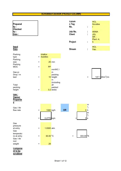
Column Tag No.:HCL Scrubber Job No.:4506A Client :JOLProject :SR - Plant -4, 5Input DataStream:HCL Vap.Packing type =Intallox Saddles Packing size =25mm Packing MOC=PP Gas pr. Drop / m bed =15mmWC / m packing height =147.1(N/m 2)/mTotal packing height= 3.2m (including all packed beds)Gas / Vapour Properties Gas / Air flow rate =OR0m 3/h == 0m 3/sGas pressure at entry = 1.0000atmGas temperature at entry =30.00oC =303.00oKGas / Air mol weight=29Component to be scrubbed Component Name =HCL VapComponent flow rate =70Kg/h % comp. in air/gas =6% (v/v)Molecular weight of comp.=36.53Conversion :Liquid Viscosity, µL =0.0035000Ns/m 2 3.5C p =Ns/m 2Packing factor, F p=21m -1Charac. Packing Factor,C f =33 Ref. Table 6.3, Characterstics of Random packingsConversion factor, J = 1.0factor for adequate liquid distribution & irrigation across the bedSCRUBBER DESIGN (PACKED COLUMN)0.00350000CalculationsSince larger flow quantities are at the bottom for an absorber, the diameter will be chosen to accommodate the bottom conditions.To calculate Gas density Avg. molecular weight =29.45Kg / KmolSelect vol. flow rate and mass flow rate from above,Selected mass flow rate =0.277778Kg/sSelected vol. Flow rate =0.234499m 3/s Selected molar flow rate =0.009432Kmol/s Therefore, gas density=1.1846Kg/m 3(mass flow rate / vol. Flow rate)To find L', G' and Tower c/s areaAssuming essentially complete absorbtion, Component removed =0.0207Kg/s (molar flow rate x % comp. x mol. Wt.)Liquid leaving =0.0420Kg/s (Inlet liquid flow rate + comp. Removed)0.5=0.00497Using0.00497as ordinate, Refer fig.6.34 using a gas pressure drop of 147.1(N/m 2)/mG' 2 C f µL 0.1 J =0.04 (from graph)G ) g c Therefore, G'=0.5=1.6665Kg / m 2.s Tower c/s area =0.1667m2( c/s area = mass flow rate / G' )Tower diameter=0.4607m =460.7mm=500mm Corresponding c/s area=0.1963m 2TO CALCULATE COLUMN DIAMETEREfficiency of fan / blower=60%To calculate pressure drop Pressure drop for irrigated =470.72N/m 2(pressure drop per m packing x total ht. of packing)packingFor dry packing,O/L Gas flow rate, G'=2.s (Gas inlet flow rate - Component removed) / c/s areaO/L Gas pressure=2(subtracting pressure drop across packing)= gas mol wt. x 273 x gas o/l pr. 22.41m3/Kmol T in kelvin 101330=C D =96.7 Ref. Table 6.3, Characterstics of Random packingsDelta P = Z=2Pressure drop for packing =613.61N/m 2(irrigated packing + dry packing)Pressure drop for internals =25mmWC(packing supports and liquid distributors)=245.17N/m2Gas velocity=7.5m/sInlet expansion & outlet = 1.5 x Velocity heads = 1.5 x (V 2/ 2g)contraction losses=42.19N m / Kg=49.97N/m 2(divide by density)Total pressure drop =908.75N/m2(packing + internals + losses)Fan power output=pressure drop,N/m 2 x (gas in - component removed) Kg/sO/L gas density, Kg/m 3=201.35N .m / s =0.20kW Power for fan motor=0.34kW (fan power output / motor efficiency)=0.45hpTO ESTIMATE POWER REQUIREMENTLiq.-Vap. Flow factor, F LV==Design for an initial pressure drop of15mm H2O /m packingFrom K 4v/s F LV ,K 4=0.85K 4 at flooding =6.50Trial % flooding==Gas mass flow rate, V m==3.7763kg/m 2.s Trial column c/s area=V / V m (Trial A s )=0.0736m 2Trial column dia., D =0.3060mD = (4/pi) x Trial A sRound off 'D' to nearest standard size Therefore, D =0.500mColumn C/S area, A s=0.1963m2A s =(pi/4) x D2% flooding =13.5472% flooding = Trial % flooding x (Trial A s / A s )ConclusionGenerally packed towers are designed for 50% -- 85% flooding.If flooding is to be reduced,(i) Select larger packing size and repeat the above steps.OR(ii) Increase the column diameter and repeat the above steps.COLUMN DIAMETER / HYDRAULIC CHECK(1/2)Input Data 0.018 N/m =dyne/cm Liquid-phase Surface Tension, =20dyne/cm Liquid Viscosity = 3.5cP n=1.13080Calculation ln HETP =0.837437HETP==For separations, less than 15 theoritical stages, a 20% design safety factor can be applied.Considering 20% safety factor, HETP =0.845065mFor separations, requiring 15 to 25 theoritical stages, a 15% design safety factor can be applied.HETP =HETP PREDICTIONNorton's Correlation Applicable Norton's Correlation NOT applicable18。
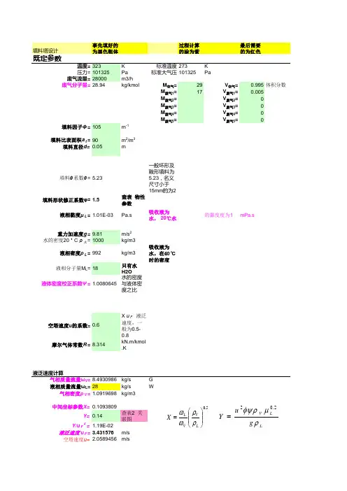
预先填好的填料塔设计为黑色粗体既定参数温度 = 323压力 = 101325废气流量 = 28000废气分子量填料因子Φ= 105填料比表面积at = 90 填料直径填料θ系数θ填料形状修正系数φ=液相黏度μL重力加快度 g = 9.81水的密度 20? C ρ水= 1000液相密度ρL = 992液相分子量 M L= 18液体密度校订系数Ψ过程计算最后需要的涂为紫的为红色K 标准温度 273 KPa 标准大气压 101325 Pam3/hkg/kmol M空气 = 29 V空气 = 0.995 体积分数M废气1= 17 V废气1=M废气2= V废气2= 0M废气3= V废气3= 0M废气4= V废气4= 0M废气5= V废气5= 0m-1m2/m 3m一般环形及鞍形填料为5.23 ,名义尺寸小于查表物性15mm 的为 2参数汲取液为的黏度度为 1水, 20 ℃水m/s 2kg/m3汲取液为kg/m3 水,在40°C只有水时的密度H2O水的密度与液体密度之比X u F液泛速度,一空塔速度 u 的系数般为摩尔气体常数.K液泛速度计算气相质量流量ωV kg/s G 液相质量流量ωL= 28 kg/s W气相密度ρV kg/m3中间坐标参数查表2 关u 2 0 .2X L V VL联图Yg Y/u F 2V L L 液泛速度uF m/s空塔速度m/s有效过流截面按圆型填料塔计算塔径直径取整塔截面积Ω=4.9087385 实质空塔速度塔径 /填料径 = 50喷淋密度 L'=湿润速率Lw =计算工作压损参数P/Z= 254填料层高度计算2mm直径m 查塔径参数2m要求 >10m3/m 2 .hd<75,(L w)min=0.08m3/m 2 .hd>75,(L w)min=0.12m3/m 3. hPa/m查表2 关系图切合切合 d<75mm切合 d>75mm。
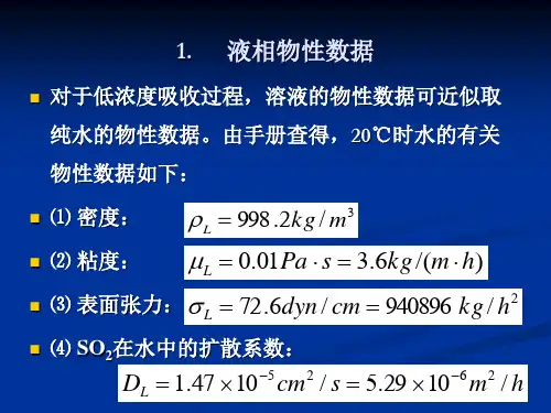
二 基础物性参数的确定1 液相物性数据对于低浓度吸收过程,溶液的物性数据可近似取纯水的物性数据。
由手册查得,2 气相物性参数设计压力:101.3kPa ,温度:20C ︒氨气在水中的扩散系数:92621.7610/ 6.33610/L D cm s m h --=⨯=⨯ 氨气在空气中的扩散系数:查表得,氨气在0°C ,101.3kPa 在空气中的扩散系数为0.17 2/cm s , 根据关系式换算出20C ︒时的空气中的扩散系数: 混合气体的平均摩尔质量为 混合气体的平均密度为混合气体的粘度可近似取空气的粘度,查手册得20C ︒空气粘度为3 气液相平衡数据由手册查得,常压下20C ︒时,氨气在水中的亨利系数 相平衡常数 溶解度系数4 物料衡算进塔气相摩尔比 出塔气相摩尔比 混合气体流量 惰性气体摩尔流量该吸收过程属低浓度吸收,平衡关系为直线,最小液气比可按下式计算:对于纯溶剂吸收过程,进塔液相组成 取操作液气比为5 吸收塔的工艺尺寸计算5.1 塔径计算采用Eckert 通用关联图计算泛点气速。
Eckert 通用关联图: 气体质量流量为液体质量流量可近似按纯水的流量计算: Eckert 通用关联图的横坐标为 根据关联图对应坐标可得 由表2-4-1可知 F φ=260 1m -取 0.80.8 2.360 1.888/F u u m s ==⨯=由1.737D ===m圆整塔径(常用的标准塔径有400mm 、500mm 、600mm 、800mm 、1000mm 、1200mm 、1400mm 、1600mm 、2000mm 、2200mm 等)本设计方案取D=2000mm 。
泛点率校核:因为填料塔的适宜空塔气速一般取泛点气速的50%-80%,泛点率值在允许范围内。
填料塔规格校核:200080825D d ==>(在允许范围之内) 液体喷淋密度校核: 取最小润湿速率为 由表2-4-1可知: 由于喷淋密度过小,可采用增大回流比或采用液体再循环的方法加大液体流量,以保证填料的润湿性能;也可适当的增加填料层高度的办法予以补偿。
2前言炼焦化学产品在国民经济中占有重要地位,炼焦化学工业是国民经济的一个重要部门,它是钢铁联合企业的主要组成部分之一,也是煤炭的综合利用工业。
焦炉煤气中所含的氨可用于制取硫酸铵、浓氨水或无水氨;煤气中主要成分---氢,可用于制造合成氨。
进一步制取尿素、硝酸铵、磷酸铵和碳酸铵等化肥,均可以直接用于农业生产。
焦炉煤气中含有很多焦油、粗苯、氨等多种具有回收价值的化工产品。
由于环保问题日益成为政府部门和社会公众关注的焦点,氨的排放量和排放浓度成为焦化厂需要重点控制和解决的问题,其次,提高氨的回收利用,不仅有利于促进环境保护,更是具有循环经济效益的头等大事。
在化学工业中,经常需要将气体混合物中的各个组分加以分离,其主要目的是回收气体混合物中的有用物质,以制取产品,或除去工艺气体中的有害成分,使气体净化,以便进一步加工处理,或除去工业放空尾气中的有害成分,以免污染空气。
吸收操作是气体混合物分离方法之一,它是根据混合物中各组分在某一种溶剂中溶解度不同而达到分离的目的。
塔设备是化工生产中重要的设备。
它使气液或液液两相之间进行紧密接触,达到传质及传热的目的。
填料塔具有结构简单、便于用耐腐蚀材料制造、适于小直径塔的场合以及压降小等优点。
塔填料的性质决定了填料塔的操作,只有性能优良的塔填料再辅以理想的塔内件,才有望构成技术上先进的填料塔。
人们对塔填料的研究十分活跃。
对塔填料改进与更新的目的在于:改善流体的均匀分布,提高传递效率,减少流动阻力,增大流体的流量以满足降耗、节能、设备放大、高纯产品制备等各种需要。
目前,塔填料的开发,除研究各种散装和规整填料结构外,还对填料的材质、加工方法、表面特性等进行研究。
近年来由于填料塔结构的改进,新型的、高负荷填料的开发,既提高了塔的通过能力和分离效能又保持了压降小、性能稳定等特点。
因此,填料塔已经被推广到大型气、液操作中,在某些场合还代替了传统的板式塔。
如今,直径几米甚至几十米的大型填料塔在工业上已非罕见。
Column TagNo.:HCL Scrubbe rJob No.:4506A Client:JOLProject:SR -Plant -4, 5InputData Stream:HCL Vap.Packingtype=Intallox SaddlesPackingsize=25mm PackingMOC=PPGas pr.Drop / mbed=15mmWC /mpackingheight=147.1(N/m2)/mTotalpackingheight= 3.2m (including all packed beds)Gas / Vapour Propertie sGas / Airflow rate=1000kg/h OR0m 3/ h=0.2778kg/s=0m 3/ sGaspressureat entry= 1.0000atmGastemperature at entry=30.00o C=303.00o K Gas / Airmolweight=29Component to bescrubbedSCRUBBER DESIGN (PACKED COLUMN)nt Name=HCL Vap Component flowrate=70Kg/h % comp.in air/gas=6% (v/v)Molecularweight ofcomp.=36.5Liquid /Scrubbing mediaPropertiesScrubbingmedia=20% NaOHLiquid flowrate, L=77kg/h =0.0214kg/sLiquid Density,L =1100kg/m3Conversion :LiquidViscosity,=0.0035000Ns/m2 3.5C p =Ns/m2 Packingfactor, F p=21m-1Charac.PackingFactor,C f=33 Ref. Table 6.3, Characte rstics of Random packingsConversion factor, J= 1.0factor foradequateliquiddistribution &irrigationacrossthe bed0.00350000onsTO CALCULATE COLUMN DIAMETER Sincelarger flowquantitiesare at thebottom foranabsorber,thediameterwill bechosen toaccommodate thebottomconditions.TocalculateGasdensityAvg.molecularweight=29.45Kg / KmolSelect vol.flow rateand massflow ratefromabove,Selectedmass flowrate=0.277778Kg/s Selectedvol. Flowrate=0.234499m3/s Selectedmolar flowrate=0.009432Kmol/sTherefore, gasdensity= 1.1846Kg/m3(mass flow rate / vol. Flow rate)To findL', G' and Tower c/s area Assuming essentially complete absorbtion ,Compone ntremoved=0.0207Kg/s(molarflowrate x %comp. xmol.Wt.)Liquidleaving=0.0420Kg/s (Inlet liquid flow rate + comp. Remov ed)0.5=Using0.00497asordinate,Referfig.6.34using agaspressuredrop of147.1(N/m2)/m G' 2 C fµL0.1 J=0.04(fromgraph)- G) g cTherefore,G'=0.5LJ= 1.6665Kg / m2.sTower c/sarea=0.1667m2( c/sarea =massflowrate / G')Towerdiameter=0.4607m=460.7mm=500mmCorresponding c/sarea=0.1963m2TO ESTIMATE POWER REQUIREMENTEfficiencyof fan /blower=60%TocalculatepressuredropPressuredrop forirrigated=470.72N/m2(pressu re drop per m packingx totalht. ofpacking)packingFor drypacking,O/L Gasflow rate,G'=2.s(Gasinletflowrate -Componentremoved) / c/sareaO/L Gaspressure=2(subtractingpressure dropacrosspacking)Gasdensity,G=gas o/lpr.kelvin101330= 1.1605Kg/m3C D=96.7Ref.Table6.3,Characterstics ofRandompackingsDelta P =Z=2Pressure drop for packing=613.61N/m 2(irrigate dpacking + dry packing )Pressure drop for internals=25mmWC (packin gsupport s and liquid distribut ors)=245.17N/m 2Gas velocity =7.5m/sInletexpansion & outlet = 1.5 x Velocity heads =1.5 x (V 2 / 2g)contractio n losses=42.19N m / Kg=49.97N/m 2(divide bydensity)Total pressure drop=908.75N/m 2(packin g +internal s +losses)Fan power output=pressure drop,N/m 2x (gas in -componen t removed)Kg/sO/L gas density,3=Power for fan motor=0.34kW(fan power output /motor efficien cy)=0.45hpLiq.-Vap.Flowfactor, F LV=(L / V) x (V / L )=0.0025Design foran initial pressure drop of 15mm H2O /m packingFrom K 4v/s F LV ,K 4=0.85K 4 at flooding= 6.50Trial %flooding=( (K 4 /K 4 at flooding)) x 100=36.1620Gas mass flow rate,V m= 13.1 F p (µL / L )0.1=3.7763kg/m 2.sTrial column c/s area =V / V m(Trial A s )=0.0736m 2Trial column dia., D=0.3060mD = (4/pi) x Trial A sRound off 'D' to nearest standard sizeTherefore,D=0.500mCOLUMN DIAMETER / HYDRAULIC CHECK(1/2)Column C/S area,A s=0.1963m2A s =(pi/4) xD2% flooding=% flooding = Trial % flooding x (Trial A s / A s)Conclusi on Generally packed towers are designed for 50% --85% flooding. If flooding is to be reduced, (i) Select larger packing size and repeat the above steps.OR(ii) Increase the column diameter and repeat the above steps.Norton's Correlati on :ln HETP= n -0.187 ln+ 0.213 lnµApplicablewhen,liquidphasesurfacetension >4 dyne/cm& < 36dyne/cmliquidviscosity> 0.08 cP& < 0.83cPConversion :Input Data0.018 N/m =dyne/cm Liquid-phaseSurface Tension,=20dyne/cm Liquid Viscosity= 3.5cP n= 1.13080Calculationln HETP=HETP =2.310437ft =0.704221mHETP PREDICTIONNorton's Correlation Applicable Norton's Correlation NOT applicable 18Forseparations, lessthan 15theoriticalstages, a20%designsafetyfactor canbeapplied.Considering 20%safetyfactor,HETP=Forseparations,requiring15 to 25theoriticalstages, a15%designsafetyfactor canbeapplied.Considering 15%safetyfactor,HETP=0.809854m。
填料吸收塔设计任务书一、设计题目填料吸收塔设计二、设计任务及操作条件1、原料气处理量:5000m3/h。
2、原料气组成:98%空气+2.5%的氨气。
3、操作温度:20℃。
4、氢氟酸回收率:98%。
5、操作压强:常压。
6、吸收剂:清水。
7、填料选择:拉西环。
三、设计内容1.设计方案的确定及流程说明。
2.填料吸收塔的塔径,填料层的高度,填料层的压降的计算。
3.填料吸收塔的附属机构及辅助设备的选型与设计计算。
4.吸收塔的工艺流程图。
5.填料吸收塔的工艺条件图。
目录第一章设计方案的简介 (4)第一节塔设备的选型 (4)第二节填料吸收塔方案的确定 (6)第三节吸收剂的选择 (6)第四节操作温度与压力的确定 (7)第二章填料的类型与选择 (7)第一节填料的类型 (7)第二节填料的选择 (9)第三章填料塔工艺尺寸 (10)第一节基础物性数据 (10)第二节物料衡算 (11)第三节填料塔的工艺尺寸的计算 (12)第四节填料层压降的计算 (16)第四章辅助设备的设计与计算 (16)第一节液体分布器的简要设计 (16)第二节支承板的选用 (17)第三节管子、泵及风机的选用 (18)第五章塔体附件设计 (20)第一节塔的支座 (20)第二节其他附件 (20)第一章设计方案的简介第一节塔设备的选型塔设备是化工、石油化工、生物化工制药等生产过程中广泛采用的气液传质设备。
根据塔内气液接触构件的结构形式,可分为板式塔和填料塔两大类。
1、板式塔板式塔为逐级接触式气液传质设备,是最常用的气液传质设备之一。
传质机理如下所述:塔内液体依靠重力作用,由上层塔板的降液管流到下层塔板的受液盘,然后横向流过塔板,从另一侧的降液管流至下一层塔板。
溢流堰的作用是使塔板上保持一定厚度的液层。
气体则在压力差的推动下,自下而上穿过各层塔板的气体通道(泡罩、筛孔或浮阀等),分散成小股气流,鼓泡通过各层塔板的液层。
在塔板上,气液两相密切接触,进行热量和质量的交换。
Column Tag No.:HCL Scrubber Job No.:4506A Client :JOLProject :SR - Plant -4, 5Input DataStream:HCL Vap.Packing type =Intallox Saddles Packing size =25mm Packing MOC=PP Gas pr. Drop / m bed =15mmWC / m packing height =147.1(N/m 2)/mTotal packing height= 3.2m (including all packed beds)Gas / Vapour Properties Gas / Air flow rate =OR0m 3/h == 0m 3/sGas pressure at entry = 1.0000atmGas temperature at entry =30.00oC =303.00oKGas / Air mol weight=29Component to be scrubbed Component Name =HCL VapComponent flow rate =70Kg/h % comp. in air/gas =6% (v/v)Molecular weight of comp.=36.53Conversion :Liquid Viscosity, µL =0.0035000Ns/m 2 3.5C p =Ns/m 2Packing factor, F p=21m -1Charac. Packing Factor,C f =33 Ref. Table 6.3, Characterstics of Random packingsConversion factor, J = 1.0factor for adequate liquid distribution & irrigation across the bedSCRUBBER DESIGN (PACKED COLUMN)0.00350000CalculationsSince larger flow quantities are at the bottom for an absorber, the diameter will be chosen to accommodate the bottom conditions.To calculate Gas density Avg. molecular weight =29.45Kg / KmolSelect vol. flow rate and mass flow rate from above,Selected mass flow rate =0.277778Kg/sSelected vol. Flow rate =0.234499m 3/s Selected molar flow rate =0.009432Kmol/s Therefore, gas density=1.1846Kg/m 3(mass flow rate / vol. Flow rate)To find L', G' and Tower c/s areaAssuming essentially complete absorbtion, Component removed =0.0207Kg/s (molar flow rate x % comp. x mol. Wt.)Liquid leaving =0.0420Kg/s (Inlet liquid flow rate + comp. Removed)0.5=0.00497Using0.00497as ordinate, Refer fig.6.34 using a gas pressure drop of 147.1(N/m 2)/mG' 2 C f µL 0.1 J =0.04 (from graph)G ) g c Therefore, G'=0.5=1.6665Kg / m 2.s Tower c/s area =0.1667m2( c/s area = mass flow rate / G' )Tower diameter=0.4607m =460.7mm=500mm Corresponding c/s area=0.1963m 2TO CALCULATE COLUMN DIAMETEREfficiency of fan / blower=60%To calculate pressure drop Pressure drop for irrigated =470.72N/m 2(pressure drop per m packing x total ht. of packing)packingFor dry packing,O/L Gas flow rate, G'=2.s (Gas inlet flow rate - Component removed) / c/s areaO/L Gas pressure=2(subtracting pressure drop across packing)= gas mol wt. x 273 x gas o/l pr. 22.41m3/Kmol T in kelvin 101330=C D =96.7 Ref. Table 6.3, Characterstics of Random packingsDelta P = Z=2Pressure drop for packing =613.61N/m 2(irrigated packing + dry packing)Pressure drop for internals =25mmWC(packing supports and liquid distributors)=245.17N/m2Gas velocity=7.5m/sInlet expansion & outlet = 1.5 x Velocity heads = 1.5 x (V 2/ 2g)contraction losses=42.19N m / Kg=49.97N/m 2(divide by density)Total pressure drop =908.75N/m2(packing + internals + losses)Fan power output=pressure drop,N/m 2 x (gas in - component removed) Kg/sO/L gas density, Kg/m 3=201.35N .m / s =0.20kW Power for fan motor=0.34kW (fan power output / motor efficiency)=0.45hpTO ESTIMATE POWER REQUIREMENTLiq.-Vap. Flow factor, F LV==Design for an initial pressure drop of15mm H2O /m packingFrom K 4v/s F LV ,K 4=0.85K 4 at flooding =6.50Trial % flooding==Gas mass flow rate, V m==3.7763kg/m 2.s Trial column c/s area=V / V m (Trial A s )=0.0736m 2Trial column dia., D =0.3060mD = (4/pi) x Trial A sRound off 'D' to nearest standard size Therefore, D =0.500mColumn C/S area, A s=0.1963m2A s =(pi/4) x D2% flooding =13.5472% flooding = Trial % flooding x (Trial A s / A s )ConclusionGenerally packed towers are designed for 50% -- 85% flooding.If flooding is to be reduced,(i) Select larger packing size and repeat the above steps.OR(ii) Increase the column diameter and repeat the above steps.COLUMN DIAMETER / HYDRAULIC CHECK(1/2)Input Data 0.018 N/m =dyne/cm Liquid-phase Surface Tension, =20dyne/cm Liquid Viscosity = 3.5cP n=1.13080Calculation ln HETP =0.837437HETP==For separations, less than 15 theoritical stages, a 20% design safety factor can be applied.Considering 20% safety factor, HETP =0.845065mFor separations, requiring 15 to 25 theoritical stages, a 15% design safety factor can be applied.HETP =HETP PREDICTIONNorton's Correlation Applicable Norton's Correlation NOT applicable18。