Fisher阀门6200定位器原理及调试
- 格式:pdf
- 大小:6.28 MB
- 文档页数:46
HART协议是由Rosemount企业开发的一套通信标准,协议采纳标准的Bell202 移频键控信号,以1200/2200波特率的正弦信号叠加在4-20mA直流信号长进行通信。
它可使模拟信号和数字信号同时进行双向通信而不相互扰乱。
手操器和模拟信号发生器并联接入定位器的输入端。
DVC6200调试步骤详解一、DVC6200与475通信器阀门校检调试步骤二、定位器反应调试使用说明三、DVC自行程校检按钮激活四、DVC整定设定五、DVC6200与475通信器阀门指引设置校检调试步骤六、DVC6200的模拟输出激活方法一、DVC6200与475通信器阀门校检调试步骤1、进入界面,选择HART2、选择online后enter(确认键)3、3、若有报警信号,选择YES后enter(确认键)4、online下拉菜单项选择择configure(组态)后按enter(确认键)5、选择calibration(校检)菜单后按enter(确认键)6、选择auto calibration7、警示菜单项选择择outofservice8、选择CONTINUE后enter(确认键)选择travelcontrol9、阀门自动校验无须操作,只要等候直到下列图界面10、自动校验达成OK键确认11、选择OK 12、改正成为inservice状态,校检达成。
供气压力履行机构开关位二、定位器反应调试使用说明1、在configure(组态)菜单项选择择manualsetup2、选择模式保护将inservice 改为OUTOFservice3、选择改变仪表模式4、选择outofservice。
Enter(确认键)后返回5、温馨提示选择OK6、在manualsetup中选择outputs用来设定定位器反应7、选择outputterminal8、选择outputterminal9、选择enable后enter(确认键)10、必定要选择send发送后达成反应使用设置。
HART手操器调试fisher费希尔dvc6200阀门定位器HART调试FISHERdvc6200阀门定位器DVC6200与475通讯器阀门校检调试步骤进入界面,选择HART1、离线2、在线3 、多功能4、诊断选择online后enter找到两个非零状态码、忽略下一个50状态的发生1、供给压力低报警2、需要维护如有报警信号,选择YES后enter1、概述2、组态、配置3、维修工具online 下拉菜单选择configure(组态)后按enter1、引导设置2、手动设置3、报警设置4、校验选择calibration(校检)菜单后按enter1、自动校验2、手动校验3、校验类型4、校验时间5、校准器6、上次自动校准状态选择autocalibration警告菜单选择outofservice警告:校准会照成仪器的输出突然变化及其它损失1、继续2、退出选择CONTINUE 后enter选择travelcontrol阀门自动校验无须操作,只需等待直到下图界面自动校验完成OK键确认选择OK注意:要细调相应,使用性能调节器在仪器处于维修模式时,阀门可能会移动在服务/运行中止服务修改成为inservice状态,校检完成。
定位器反馈调试使用说明:1、引导设置2、手动设置3、报警设置4 、校准在configure(组态)菜单选择manualsetup1、模式与保护2、仪器3、行程、压力控制4、整定5、阀门与执行机构6、输出选择模式保护将inservice改为OUTOFservice1、仪器模式中止服务2、更换仪器3、写保护禁用4、更改保护帮助发送菜单选择改变仪表模式警告!在以下情况下输出将不跟踪输入模式以停用在服务中止服务选择o utofservice。
Enter后返回提醒:仪器必须返回到用于跟踪输入的输出服务温馨提醒OK手动设定1、模式与保护2、仪器3、行程、压力控制4、整定5、阀门与执行机构6、输出值保存菜单主页在manualsetup中选择outputs用来设定定位器反馈输出1、输出终端组态2、开关组态3、变送器输出4mA时=阀关4、HART变量分配选择outputterminal输出配置1、输出端激活/禁用2、功能发送器3、失败信号发射低/··选择outputterminalenable输出端选择启用禁用启用禁用选择enable后enter输出端配置1、输出启用2、功能变送器3、失败信号发射低/·发送主页一定要选择send发送后完成反馈使用设置。
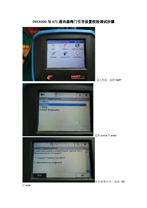
DVC6200与475通讯器阀门引导设置校检调试步骤
进入界面,选择HART
选择online后enter
如有报警信号,选择YES 后enter
online下拉菜单选择configure(组态)后按enter
选择guided setup(引导设置)菜单后按enter
选择device setup
警告菜单选择out of service
压力单位选择可任意,选择PSI
放大器类型,选择A OR C用于单作用和双作用放大器,B为反作用定位器。
选择travel control
执行器制造厂商选择fisher
执行器的型号更具执行器名牌选择。
执行器尺寸型号选择根据执行器名牌进行输入
失电阀门开或者关,据条件选择
选择YES
定位器自动捕行程传感器方向。
等待下图界面弹出
是否含有快排和气体流量放大器,没有选择no。
否则YES
发送设备设置数据给仪表,按enter
等待发送,发送完成后如下图界面
使用工厂默认设置选择YES
发送工厂默认数据中,等待完成后出现下图界面
设备设置完成选OK,按Enter
运行阀门行程校验,选择ok后enter
选择yes
阀门自动校验中
阀门自动校验中
自动校验中
阀门校检完成ok后按enter
选择ok
校验完成后恢复到in service 状态。
阀门自动校验步骤完成。
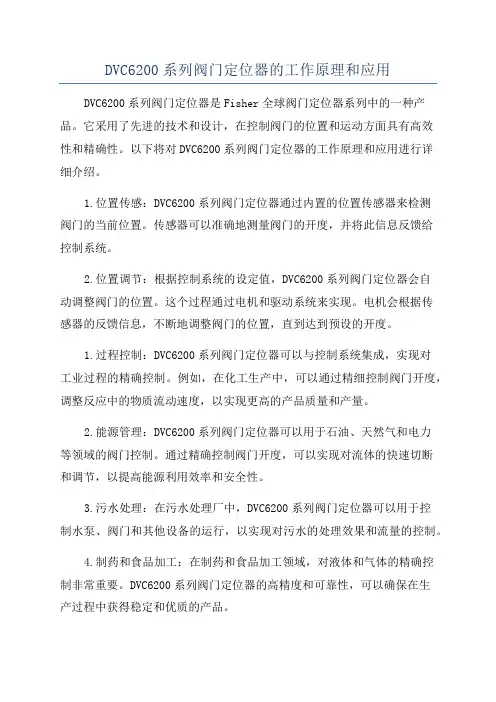
DVC6200系列阀门定位器的工作原理和应用DVC6200系列阀门定位器是Fisher全球阀门定位器系列中的一种产品。
它采用了先进的技术和设计,在控制阀门的位置和运动方面具有高效性和精确性。
以下将对DVC6200系列阀门定位器的工作原理和应用进行详细介绍。
1.位置传感:DVC6200系列阀门定位器通过内置的位置传感器来检测阀门的当前位置。
传感器可以准确地测量阀门的开度,并将此信息反馈给控制系统。
2.位置调节:根据控制系统的设定值,DVC6200系列阀门定位器会自动调整阀门的位置。
这个过程通过电机和驱动系统来实现。
电机会根据传感器的反馈信息,不断地调整阀门的位置,直到达到预设的开度。
1.过程控制:DVC6200系列阀门定位器可以与控制系统集成,实现对工业过程的精确控制。
例如,在化工生产中,可以通过精细控制阀门开度,调整反应中的物质流动速度,以实现更高的产品质量和产量。
2.能源管理:DVC6200系列阀门定位器可以用于石油、天然气和电力等领域的阀门控制。
通过精确控制阀门开度,可以实现对流体的快速切断和调节,以提高能源利用效率和安全性。
3.污水处理:在污水处理厂中,DVC6200系列阀门定位器可以用于控制水泵、阀门和其他设备的运行,以实现对污水的处理效果和流量的控制。
4.制药和食品加工:在制药和食品加工领域,对液体和气体的精确控制非常重要。
DVC6200系列阀门定位器的高精度和可靠性,可以确保在生产过程中获得稳定和优质的产品。
总结:DVC6200系列阀门定位器是一种基于电气信号的位置控制系统,通过精确的位置传感和位置调节,实现对阀门的精确控制。
它在各个领域的工业应用中起着非常重要的作用,特别适用于过程控制、能源管理、污水处理和制药食品加工等领域。
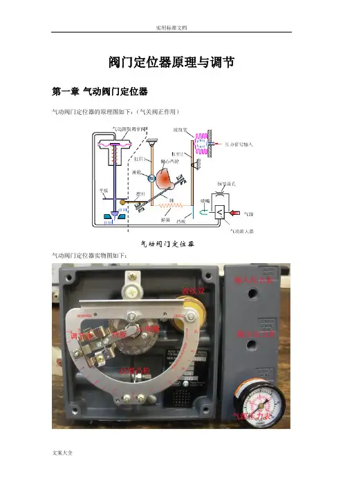
阀门定位器原理与调节第一章气动阀门定位器气动阀门定位器的原理图如下:(气关阀正作用)气动阀门定位器实物图如下:气动阀门定位器是按力平衡原理设计工作的,其工作原理方框见上图所示,它是按力平衡原理设计和工作的。
如图上图所示当通入波纹管的信号压力增加时,使杠杆2绕支点转动,档板靠近喷嘴,喷嘴背压经放大器放大后,送入薄膜执行机构气室,使阀杆向下移动,并带动反馈杆(摆杆)绕支点转动,连接在同一轴上的反馈凸轮(偏心凸轮)也跟着作逆时针方向转动,通过滚轮使杠杆1绕支点转动,并将反馈弹簧拉伸、弹簧对杠杆2的拉力与信号压力作用在波纹管上的力达到力矩平衡时仪表达到平衡状态。
此时,一定的信号压力就与一定的阀门位置相对应。
以上作用方式为正作用,若要改变作用方式,只要将凸轮翻转,A向变成B向等,即可。
所谓正作用定位器,就是信号压力增加,输出压力亦增加;所谓反作用定位器,就是信号压力增加,输出压力则减少。
要改变正反作用,Fisher的阀只需要把里面的调节盘拨到另一侧即可。
一台正作用执行机构只要装上反作用定位器,就能实现反作用执行机构的动作;相反,一台反作用执行机构只要装上反作用定位器,就能实现正作用执行机构的动作。
至于气开阀,由于是在膜盒下面通气,需要将如图中的凸轮反转。
第二章电气阀门定位器由于现在DCS在现场使用越来越多,很多控制器都是使用了中控系统的控制器,所以中控到现场的都是4-20mA的电信号,到现场又需要阀动作的比较快。
虽然阀门定位器由最初的气/气阀门定位器、电/气阀门定位器发展到现在的数字阀门定位器、区域总线阀门定位器,但它们的基本原理和主要功能都没有大的改变。
定位器中基本自控元件介绍--电/气转换器原理随着仪表技术的发展,气动仪表领域已逐步被电动仪表和计算机控制所占领,现在只有在一些特殊的场合还在使用气动仪表,作为仪表中的阀门附件“定位器”也由原来的气动阀门(P/P)定位器逐步由电/气(E/P)阀门定位器所代替。
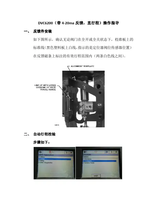
DVC6200(带4-20ma 反馈反馈,,直行程直行程))操作指导一、 反馈件安装如下图所示,确认无论阀门在全开或全关状态下,校准板上的标准线(黑色塑料板上白线,指示的是定位器阀位传感器位置)在反馈磁条上标注的有效行程范围内(两条白色线之间)。
二、 自动行程校验步骤如下步骤如下::定位器将自动开始行程校验校验完成后必须将定位器投入校验完成后必须将定位器投入““In Service”模式模式。
三、 反馈信号设置1\ 功能激活注意:选择”SEND” 发送后才能完成阀位反馈功能激活。
2\反馈信号正反作用设置:在下面这个菜单的第3项Transmitter of Output 里,可以选择阀门在关闭状态或全开状态下反馈信号为4m A.四、调试按钮:在manual setup 菜单下功能激活:1\功能激活选择send 发送完成接线盒自行程校检按钮设置。
2\按压调试按钮3-10秒钟秒钟,,阀门将自动进行行程校验阀门将自动进行行程校验。
五、 灵敏度灵敏度的的调整如发现阀门有震荡,或阀门动作过慢。
可通过Tuning Set(简单理解为灵敏度)的调整进行改善。
点击send 发送。
有 C D E F G H I J K L M 可选,C 阀门反应最慢,M 阀门反应最快,反应越快越容易引起震荡。
六、 Instrument Mode 的设置设置::在进行定位器校验在进行定位器校验、、参数调整时参数调整时,,一般需要将Instrument Mode 置于Out Of Service (或者Not In Service )状态状态,,校验校验、、调整完成后必须投入In Service!。


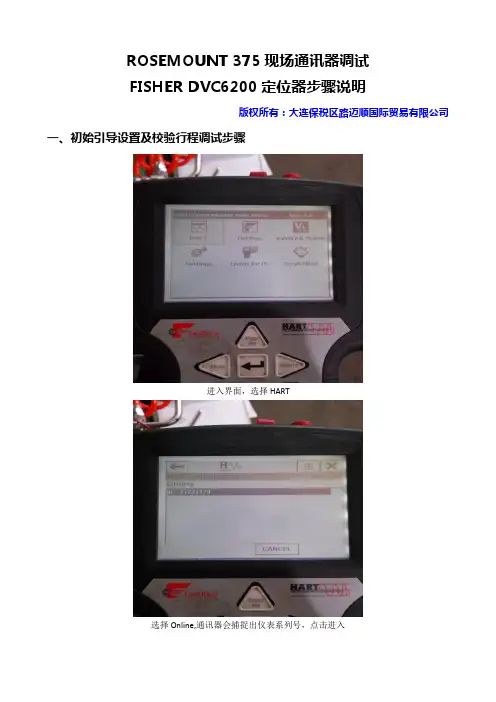
ROSEMOUNT 375现场通讯器调试FISHER DVC6200定位器步骤说明版权所有:大连保税区路迈顺国际贸易有限公司一、初始引导设置及校验行程调试步骤进入界面,选择HART选择Online,通讯器会捕捉出仪表系列号,点击进入Online下拉菜单选择Configure(组态)选择Setup Wizard警告菜单选择Out of Service放大器类型,选择A or C用于单作用和双作用放大器,B为反作用定位器。
仪表选择,6200 or 6000选择Travel Control行程控制压力单位可选psi根据执行机构铭牌指示的最大压力填入执行器制造厂商选择Fisher(如果是国产执行机构,可根据具体参数对应Fisher执行机构来选)执行机构的型号根据执行机构铭牌来选择。
执行机构尺寸型号选择同样根据执行机构铭牌进行输入根据现场执行机构安装的附件,选择是否含有流量放大器和快排阀,有选择Yes,没有选择no。
选择组态发送到仪表中,点击Send等待发送点击Yes并等待设置向导完成,点击OK提示需要自动校验行程,点击OK点击Yes等待,无需操作校验完成如果校验完后通讯器会自动弹出投用选择框,则改到In Service才能使用。
否则每次修改完参数后就要手动改成In Service状态。
可以通过Hot Key或者从Instrument Mode中改变。
可以从右上角的箭头中进入Hot Key,点击Instrument Mode选择In service也可以从Detail Setup中进入Mode and Protection中选择二、DVC6200反馈调试步骤:注意:DVC6200反馈输出回路里要有24V直流电驱动,否则即使激活反馈,系统也不会检测出反馈在Configure 菜单选择Manual Setup在Manual Setup 中选择Outputs用来设定定位器反馈输出选择Output Terminal Configure选择Output Terminal Enable,激活反馈一定要选择send 发送后完成反馈使用设置。
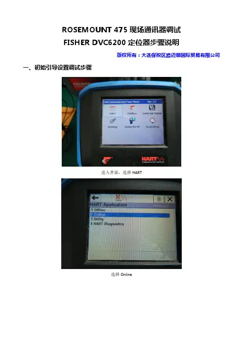
ROSEMOUNT 475现场通讯器调试FISHER DVC6200定位器步骤说明版权所有:大连保税区路迈顺国际贸易有限公司一、初始引导设置调试步骤进入界面,选择HART选择Online如有报警信号,选择YESOnline下拉菜单选择Configure(组态)选择Guided Setup(引导设置)菜单选择Device Setup警告菜单选择Out of Service压力单位选择可任意,选择Psi放大器类型,选择A or C用于单作用和双作用放大器,B为反作用定位器。
选择Travel Control行程控制执行器制造厂商选择Fisher(如果是国产执行机构,可根据具体参数对应Fisher执行机构来选)执行机构的型号根据执行机构铭牌来选择。
执行机构尺寸型号选择同样根据执行机构铭牌进行输入阀门气开气关,可根据条件选择开始驱动阀门,设置行程传感器动作,选择YES定位器自动捕捉行程传感器动作。
等待下图界面弹出根据现场执行机构安装的附件,选择是否含有流量放大器和快排阀,有选择Yes,没有选择no。
发送设备设置数据给仪表,按Enter等待发送,发送完成后如下图界面使用工厂默认设置选择YES发送工厂默认数据中,等待完成后出现下图界面设备设置完成选OK完成阀门设置,需要运行阀门自动行程校验,选择OK选择Yes阀门自动校验中,分别捕捉高、低驱动点调整输出偏离等待自动校验中阀门校检完成,点OK选择OK二、直接校验行程(引导设置已经完成,可直接进行行程校验)进入界面,选择HART选择Online如有报警信号,选择YES后enterOnline下拉菜单选择Configure选择Calibration菜单选择Auto Calibration选择非投用Out of Service选择CONTINUE 后,选择travel control阀门自动校验无须操作,只需等待直到下图界面自动校验完成OK 键确认选择OK修改为In Service 状态,校检完成。
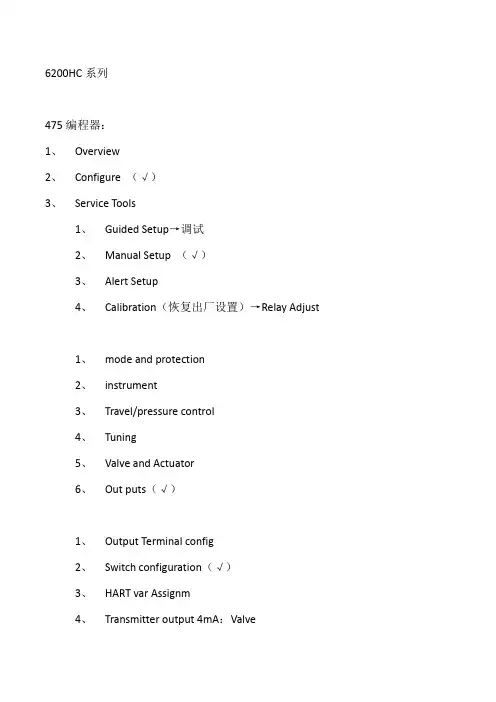
6200HC系列475编程器:1、Overview2、Configure (√)3、Service Tools1、Guided Setup→调试2、Manual Setup (√)3、Alert Setup4、Calibration(恢复出厂设置)→Relay Adjust1、mode and protection2、instrument3、Travel/pressure control4、Tuning5、Valve and Actuator6、Out puts(√)1、Output Terminal config2、Switch configuration(√)3、HART var Assignm4、Transmitter output 4mA:Valve5、BurstmaleAlert switch source→out service→(改成)Enable→in service→返回初界面→in service375编程器:1、HART Application(启动HART应用)2、自动寻找→进入online(在线)否则将进入Field communicator(现场器)菜单3、进入Setup&Diag(设置和诊断)4、Basic Setup(基本设置)5、Auto Setup(自动设置)重点:不管如何一定要保证“必须置于out service(非投用状态)”,在设定完校验完成后必须返回in service(投用状态)。
对375不太熟的用户可选择setup Wizard(设置向导),它将一步一步引导您怎样对阀门进行校验。
选择Bar输入公斤数,一般最大不能超过铭牌上的数值,以1052执行机构最大不能超过3.8Bar,对1061执行机构不能超过10bar。
执行机构确定厂商Actuator Manufacturer,如果不是Fisher厂商选others。
FIELDVUE™ DVC6200系列阀门定位器的工作原理和应用李宝华摘要:FIELDVUE™ DVC6200系列阀门定位器是FISHER 新一代高性能的阀门控制器,以响应市场需求和替代DVC6000系列,其综合现有系列的技术特长,采用经5万台DVC2000系列验证的非接触式阀位反馈测量和DVC6000系列隔爆/本安壳体以及气动架构,采用延续现有在板微处理器、应用软件和功能模块的电子部件,并且能适应所有安装连接模式,支持主流现场总线通信及使用嵌入式AMS ValveLink 预测性维护,便于系统集成,有着高适用性和高可靠性,可为用户提供更多的利益。
关键词: DVC6200系列;阀门定位器;工作原理;应用。
引言艾默生过程管理费希尔阀门部(EMERSON-Fisher )是研发数字式智能阀门定位器的领军厂家,于20年前的1992年推出第一款FIELDVUE™ DVC (Digital Valve Controllers 数字阀门控制器,简写DVC ),重点在定位控制及其扩展控制和诊断功能,先后有DVC5000系列、DVC6000系列、DVC2000系列,目前市场占有量超过100万台。
在2009年,FISHER 又推出新一代高性能FIELDVUE™ DVC6200系列,用以响应市场需求和替代DVC6000系列,其综合已有系列的技术特长,采用经5万台DVC2000系列验证的非接触式阀位反馈测量和DVC6000系列隔爆/本安壳体以及气动架构,解决了DVC6000系列阀位反馈机械连接结构复杂且故障率高和DVC2000系列仅有本安型致使GX 型控制阀无一体化隔爆型阀门定位器的问题,同时延续DVC6000系列现有在板微处理器、应用软件和功能模块的电子部件和I/P 电气转换器、气动放大器的气动部件,并且能适应所有控制阀安装连接模式和直行程范围0-6.35-606mm 、角行程范围0-45-90°;支持HART ®(包括使用无线技术Wireless HART ®)、FOUNDATION™ 现场总线(FF )、Profibus-PA 现场总线通信和FDT/DTM 及使用嵌入式AMS ValveLink 进行预测性维护,便于系统集成,有着高适用性和高可靠性,可为用户提供更多的利益。
Fisher ™ FIELDVUE ™ DVC6200f Digital Valve Controller PST Calibration and Testing using ValveLink ™ SoftwareThe test procedure contained in this Instruction Manual Supplement is to be considered as a guideline only and should be modified to address site‐specific requirements. Use this procedure in conjunction with the DVC6200 Series quick start guide (D103556X012) and the DVC6200f instruction manual (D103412X012). In addition, exercise good engineering practices and abide by specific plant safety guidelines for safe operation.For additional information on Partial Stroke Testing and associated parameters refer to Partial Stroke Test Information on page 19.PST CalibrationThis document covers the basic PST calibration, as well as details for making adjustments to the normal end, using Advanced Settings (see figure 11).Figure 1. Calibration > Partial StrokeConfirm PST TierFigure 2. Set Transducer Block to Manual23Figure 3. Enter the Desire Outgoing Ramp RateSupports separate ramp rates for outing andincoming strokesFigure 4. Enter the Desired Incoming Ramp RateAdditional ramp rates for the incoming strokeFigure 5. Enter the Minimum Travel MovementFigure 6. Partial Stroke Calibration progress45Figure 7. Partial Stroke Calibration progressWill calibrate to 30% from the normal end if the Minimum Travel Movement +Set Point Over Drive is less than 30%If it is greater than 30% the user-definedpoint will be calibratedFigure 8. Step or Ramp to Normal Position on Failed PST6Figure 9. Partial Stroke Calibration ProgressFigure 10. Calibration Procedure CompleteList of parameter values being downloaded to the deviceIf you need to make adjustments to the normal end default settings, select Advanced Settings, as shown in figure 11,and make the necessary adjustments.7Figure 11. Select Advanced Settings to Make Adjustments to the Normal EndSelect to define the normal endFigure 12. Set Travel High EndDefines the end of travelFigure 13. Enter Minimum Travel MovementIf Minimum Travel Movement + Set Point Overdrive is more than Maximum Allowable Travel then the below message is presented and you are directed to the next screen as shown in figure 1489Figure 14. Review InputsMinimum Travel Movement +PST Overdrive Amount is greater than theMaximum Allowable TravelFigure 15. Enter New Maximum Allowable TravelEnter a value greater than Minimum Travel Movement + PST Overdrive AmountFigure 16. Partial Stroke Calibration ProgressConfigurationAfter successfully calibrating the valve for PST go to the Detailed Setup FST/ PST tab and verify that the values for the parameters in the Valve Stroke Test group box are correct. Then go to the Partial Stroke group box and enable any of the behaviors required for the PST.Figure 17. Verify FST/PST Values10Once the PST has been setup and calibrated go to the VST Abnormal Criteria group box and select the criteria to be used to evaluate PST after they are run. Then, select the criteria to be used to abort a PST immediately on initiation, and the criteria to be used to prohibit a PST before initiation.Figure 18. Select VST and PST CriteriaCategorize the stroke alerts from the Valve Stroke Alerts tab into one of the Field Diagnostic Alert categories and suppress them if publishing on the segment is not desired.Figure 19. Set Valve Stroke AlertsInitiating a PST DiagnosticIf an Auto PST is desired then go to the Auto PST tab and set up the PST schedule. The instrument will present a message when the next PST becomes due. If a scheduled PST is not initiated then a PST overdue alert is generated. Figure 20. Setting Auto PSTTo run a manual PST select the Partial Stroke Test icon as shown in figure 21.Figure 21. Initiating a Manual PSTFigure 22. Upload or Delete Saved Partial Stroke DiagnosticsBefore the manual PST initiates, you are given theopportunity to upload and save the instrumentdiagnostic data to ValveLink software. Select thedatasets that are Not In Database and upload. Deletion ofthe data from the instrument is not necessary as newdata will overwrite the oldest dataset. Datasets that arenot uploaded to ValveLink software will not be accessiblein the instrument once they are overwritten by new dataFigure 23. Partial Stroke Test ProgressOutgoing StrokeIncoming StrokeFigure 24. PST Analyzed DataPST ResultFigure 25. Resulting Press/Tvl Graph ResultsMinimum PST Pause Time Enabled – PST startsincoming stroke on reaching the MinimumTravel Movement (10% in this case)Figure 26. Resulting Tvl/Time Graph ResultsSelect Mark Golden to set dataset as areference for future comparison. Thegolden dataset will be stored in theinstrument and will not overwrittenMinimum Pause Timeenabled with return leadA PST Diagnostic can be run with Minimum PST Pause Time disabled, as shown in the figure below. When Minimum PST Pause Time is disabled the pause time will be in effect when the valve reaches the desired test point, resulting in a slower PST.Figure 27. Disable Minimum PST Pause Time in FST/PST Partial StrokeMinimum PST PauseTime disabledFigure 28. Resulting Press/Tvl Graph Results with Minimum Pause Time DisabledPST travels to Minimum PST Travel + Set Point Overdrive(20% in this case)Figure 29. Resulting Tvl/Time Graph Results with Minimum Pause Time DisabledPST Pause TimeFigure 30. PST Analyzed Data with Minimum Pause Time DisabledSelect a PST style, either with or without Minimize PST Pause Time, and standardize on that style, as the data may be difficult to compare between the two styles. If the desire is to minimize the amount of time the valve is away from the normal end, then enabling Minimize PST Pause Time is recommended. If the amount of time away from the normal end is not a concern, then disabling Minimize PST Pause Time will cause the set point to pause at the end of the outgoing stroke for the travel to catchup to the set point. The results of the test with the Minimize PST Pause Time disabled will be similar to the PST as offered in earlier versions of SIS instruments.Partial Stroke Test InformationValve Stroke TestA valve stroke test is the process of taking the valve from the normal end to another target position at a preconfigured ramp rate before returning to the normal end while gathering data. The data is analyzed to evaluate the condition of the valve assembly against a set of user defined thresholds. A valve stroke test is only run if everything is normal in the instrument. A safety demand signal will always take precedence over a valve stroke test.D Valve Stroke Test, select Partial Stroke Test, Full Stroke Test, or Disable to select the test to run when the test is initiated using the VST_COMMAND parameter.D Partial Stroke Start Point defines the normal end of the valve. The valve needs to be at this end for a PST to be initiated. When a FST is initiated the valve will be moved by the test to this end before being ramped to the opposite end and ramped back. Setting this value to Not Configured will disable partial stroke tests.D Travel Open End defines, in percent (%) of calibrated travel, the point above which the valve is considered to have reached the high end.D Travel Closed End defines, in percent (%) of calibrated travel, the point below which the valve is considered to have reached the low end.D Test Pause Time is the time between the outgoing and incoming strokes of the test. The default value is 5 seconds.Pause Time will not be used if Minimum PST Pause Time is enabled. The outgoing stroke is from the normal end to the PST target and the incoming stroke is the return stroke to normal. See figure 31.D VST High Friction Breakout Pressure indicates that the breakout required a higher force than configured by the user.Refer to figure 31.D VST Low Friction Breakout Pressure indicates that the breakout required a lower force than configured by the user.Refer to figure 31.D Action On a Failed Test defines if the valve should step or ramp back on a failed stroke test.Figure 31. Valve Signature Representationj SUPPLY PRESSUREk INCOMING PRESSURE THRESHOLDl LOW FRICTION BREAKOUT PRESSURE THRESHOLD m HIGH FRICTION BREAKOUT PRESSURE THRESHOLD n OUTGOING PRESSURE THRESHOLD o TARGET TRAVEL MOVEMENT 100%TRAVELP R E S S U R EVST Abnormal & Abort Criteria D VST Abnormal CriteriaA partial stroke test is marked as abnormal if it fails one of the following criteria.The device always evaluates a PST on the following criteria:1. Target Travel achieved2. Return to the normal endIn addition to the above, any of the following can be selected to evaluate a Partial Stroke Test.1. Breakout Time2. Outgoing Pressure Threshold3. Incoming Pressure Threshold4. High Friction Breakout Pressure5. Low Friction Breakout PressureD VST Abort CriteriaThe PST is terminated and the valve is returned to the normal end. The return to the normal end will be per the user configuration for an aborted test. The abort criteria will only be active if it is added as a criteria to be evaluated during PST by adding it to the PST Abnormal Criteria.The device always aborts a PST if the Max Travel displacement is exceeded.In addition to the above, any of the following can be selected to abort a Partial Stroke Test:1. Breakout Time2. Incoming Pressure Threshold3. High Friction Breakout PressurePartial & Full StrokeD Partial StrokePST Max Travel defines how much travel displacement is allowed before the PST aborts (see figure 32).PST Minimum Travel is the percentage of total span that the valve moves away from its normal operating end of travel towards its tripped end of travel during the test. The default value is 10%.Set Point Overdrive defines the extent of the set point overdrive over the Minimum Travel Movement when the early turn around is enabled. When the early turn around is not enabled it defines the travel target.Freeze Analog / Discrete Feedbac k when enabled, freezes the corresponding feedback during a partial stroke test. Minimum PST Pause Time,when enabled, the incoming stroke is initiated as soon as the travel reaches the minimum travel movement. Refer to figure 32 for a time series representation of this parameter.Randomized PST, when enabled the instrument randomizes the target travel, for each PST.PST Randomization is defined in percent (%) of calibrated travel span, it defines the extent of randomization from the minimum travel movement towards the normal end. If the user defined randomization is too large the instrument will cap the max randomization to ensure that there will be at least 1% travel movement away from the defined normal end. Refer to figure 31.2122Figure 32. Time Series Representation of Minimum PST Pause TimeT R A V E LPAUSE TIMEj MINIMUM TRAVEL MOVEMENT k MAX. ALLOWABLE TRAVELNORMALNORMALT R A V E Ljj kTIMETIMEEARLY TURNAROUNDBREAKOUT TIMEOUT SETPOINT OVERDRIVERETURN LEADREDUCED PST TIMEOUTGOING RAMP RATEINCOMING RAMP RATERETURN LEADSETPOINT OVERDRIVEMINIMUM PST PAUSE TIMEENABLEDMINIMUM PST PAUSE TIMEDISABLED Outgoing Ramp Rate is the rate at which the valve will move during the Outgoing stroke of the Partial Stroke test. The default value is 0.25%/second.Incoming Ramp Rate is the rate at which the valve will move during the Incoming stroke of the Partial Stroke test. The default value is 0.25%/second.PST Return Lead defines the percent (%) change in setpoint to overcome the hysteresis in the valve assembly. The error between setpoint and actual error is added to this percent change. For example, if the Return Lead is set at 0.5% and there is a 1% error this will be set at 1.5%PST Breakout Timeout is the user configured amount of time before which the valve must leave the normal end during a PST.VST Outgoing Pressure Threshold defines the actuator pressure at which a partial stroke test will abort during the outgoing stroke (see figure 31). This prevents the DVC6200f from exhausting (or building) excessive pressure from/to the actuator in an attempt to move a stuck valve. During PST Calibration, the Partial Stroke Outgoing Pressure Threshold will be set automatically.VST Incoming Pressure Threshold defines the actuator pressure at which a partial stroke test will abort during the incoming stroke (see figure 31). This prevents the DVC6200f from exhausting (or building) excessive pressure from /to the actuator in an attempt to move a stuck valve.D Full StrokeFull Stroke Ramp Rate is the rate at which the valve will move during the full stroke test.FST Wait Time is the amount of time to wait for the valve to move to the normal end after initiation of the full stroke test.Full Stroke Breakout Timeout is the user configured amount of time before which the valve must leave the normal end during a full stroke test.PST ProhibitedA partial stroke test will not be initiated if any of the following user-configurable conditions are active:1. Check Bit Alert2. Drive Current3. Drive Signal4. Processor Impaired5. Travel Sensor6. Output Pressure sensor7. Supply Pressure Sensor8. Temperature Sensor9. Supply Pressure10. Temperature Limit11. Travel Deviation12. Pressure Fallback13. PST Abnormal23Emerson Automation SolutionsMarshalltown, Iowa 50158 USA Sorocaba, 18087 Brazil Cernay, 68700 FranceDubai, United Arab Emirates Singapore 128461 SingaporeThe contents of this publication are presented for informational purposes only, and while every effort has been made to ensure their accuracy, they are not to be construed as warranties or guarantees, express or implied, regarding the products or services described herein or their use or applicability. All sales are governed by our terms and conditions, which are available upon request. We reserve the right to modify or improve the designs or specifications of such products at any time without notice.Fisher, FIELDVUE, and ValveLink are marks owned by one of the companies in the Emerson Automation Solutions business unit of Emerson Electric Co.Emerson Automation Solutions, Emerson, and the Emerson logo are trademarks and service marks of Emerson Electric Co. All other marks are the property of their respective owners.Neither Emerson, Emerson Automation Solutions, nor any of their affiliated entities assumes responsibility for the selection, use or maintenance of any product. Responsibility for proper selection, use, and maintenance of any product remains solely with the purchaser and end user.。
入定位器的输入端。
DVC6200调试步骤详解一、DVC6200与475通讯器阀门校检调试步骤二、定位器反馈调试使用说明三、DVC自行程校检按钮激活四、DVC整定设定五、DVC6200与475通讯器阀门引导设置校检调试步骤六、DVC6200的模拟输出激活方法31、进入界面,选择HART 2选择online 后enter (确认键)、如有报警信号,选择YES后enter (确认键)4、online下拉菜单选择con figure (组态)后按enter (确认键)第1/11页下页5、选择calibration (校检)菜单后按enter (确认键)6、选择auto calibrati on7、警告菜单选择out of service8、选择CONTINUE后enter (确认键)选择travel control 9 、阀门自动校验无须操作,只需等待直到下图界面chftt It iMwiwvl M H* kw >1OK第2/11页上页12、修改成为in service 状态,校检完成。
、选择 out of serviceoEnter (确认键)后返回供气压力 执行机构开关位 二、定位器反馈调试使用说明1、在 con figure (组态)菜单选择 manual setup 2 3、选择改变仪表模式45、温馨提醒选择 OK6、选择模式保护将in serviceOUT OF serviceSAW4B0IT (NW改为^onTgure1J Alert i 3■礙伽 I T HPWI ^I 曹OM I b OntaM<媲 <8一eu_LW91ns-no <媲<^^§^1旺 slns-no <媲>d n 0s一enueEW<output termi nalH| TlxBVC«20C Out pvt T<1 'UllbMilt ・■・i r iNMlbiiinft 3r M■111I•号■十- r■M a 1三、DVC 自行程校检按钮激活激活前必须将阀门设置成 out of service 状态,参考定位器反馈调 试说明设置成为 out of service1、在 manual setup 菜单下选择 instrument 2 、选择9、选择 enable 后 enter 定要选择send 发送后完成反馈使用设置。
FISHER6200 485手操器校验步骤
一、校验步骤:
1进入菜单找到组态配置 2选择基本设置Guided Setup
3.仪表模式切到离线状态
4. 进去设备设置Device Setup选择压力单位。
5.选择定位器放大器作用类型
6.选择控制类型。
7.最大供气压力。
8.选择执行机构制造商
9.执行机构型号(不知道的都选其他) 10.执行机构尺寸
11.选择阀门作用形式(故障位) 12.确认好后去设置行程传感器
13.是否配置放大器,快排阀。
14.确认旁路助推器安装在阀座上。
15.确认放大器旁路助推器有旋开功能。
16.设备组态配置准备发送到仪表
17.是否使用工厂默认设置(初始化) 18.选择NO完成设备设置,运行自动行程校验
19.设备进入初始化。
20.设置完成是否切回在线模式。
二单独设置参数
挂手操器读取菜单,定位器切到离线状态下,进入手动设置菜单组态里选择valve and actuator 可修改阀门和执行机构参数。
三手操器现场给阀位
1.在维修工具菜单里选择Diagnostics
2.点击Stroke Valve给阀位。
3.是否使用特定阀位。
选择(Disabled)禁用。
4.给阀位,选择设定目标值Step to Target
5.给定自己想要的阀位值。
6.对阀位完成后,选择Done完成
7.阀位核对完后,将仪表切回在线模式In Service
四阀门自动校验
1.在组态菜单里找到校验菜单Calibration
2.选择行程校验Traver Calibration
3.选择自动校验Auto Calibration
4.是否连接自动校验选择Continue连接
5.选择校验类型。
选标准自动校验Auto Calibrate-Standard
6.点击进入后会弹出以下对话框。
①
②
7.选择NO进入自动校验。