美国TSI数字式风速计 9565系列样本
- 格式:pdf
- 大小:1.01 MB
- 文档页数:8
LAH.5Q0.951.可靠性标准 _2021.06.22__) -VW LAH.5Q0.951 可靠性试验 Version:2021.06.22 目录1.前言 ........................................................................... .............................................................................. .......................... 3 2.部件可靠性试验 ........................................................................... .............................................................................. ...... 3 2.1.试验要求 ........................................................................... .............................................................................. ............... 3 2.1.1试验设备 ........................................................................... .............................................................................. ............ 3 2.1.2 符合性证明 ........................................................................... .............................................................................. ....... 4 2.2部件描述. .......................................................................... .............................................................................. ............... 4 2.2.1 配置 ........................................................................... .............................................................................. ................... 4 2.2.2 功能变量 ........................................................................... .............................................................................. ........... 5 2.2.3 容许的功能限制 ........................................................................... .............................................................................8 2.3车辆应用要求 ........................................................................... .............................................................................. ....... 8 2.3.1.1. 工作时间(车辆寿命) ......................................................................... ............................................................... 9 2.3.1.2. 温度要求 ......................................................................................................................................................... ....... 9 2.3.1.3 电源要求 ........................................................................... .............................................................................. ........ 9 2.3.1.4. 环境影响 ........................................................................... .............................................................................. ..... 10 2.4 基本要求 ........................................................................... .............................................................................. ............ 10 2.5 电气要求 ........................................................................... .............................................................................. ............ 14 2.5.1 跳线跨接启动 ........................................................................... ...............................................................................14 2.5.2 反极性 ........................................................................... .............................................................................. ............. 14 2.5.3 绝缘电阻 ........................................................................... .............................................................................. ......... 14 2.6 机械要求 ........................................................................... .............................................................................. ............ 15 2.6.1 自由跌落 ........................................................................... .............................................................................. ......... 15 2.6.2 灰尘试验 ........................................................................... .............................................................................. ......... 15 2.6.3 振动试验 ........................................................................... .............................................................................. ......... 16 2.6.4 机械冲击 ........................................................................... .............................................................................. ......... 18 2.6.5 褶皱和插接式连接 ...........................................................................2.6.6 插入力和耦合插针强度(装配) ......................................................................... ................................................. 18 2.6.7 插针分离力(插入接触) ......................................................................... ........................................................... 19 2.6.8 电缆保持力,衔接保持力 ........................................................................... ........................................................... 21 2.6.9 拔出力 ........................................................................... .............................................................................. ............. 21 2.7 气候要求 ........................................................................... .............................................................................. ............ 22 2.7.1 老化 ........................................................................... .............................................................................. ................. 22 2.7.2 多阶段温度试验 ........................................................................... (23)2.7.3 高温操作 ........................................................................... .............................................................................. ......... 23 2.7.4 温度冲击(部件) ......................................................................... . (24)2.7.5 盐雾试验,带操作,外部 ........................................................................... ........................................................... 24 2.7.6 湿热循环 ........................................................................... .............................................................................. ......... 24 2.7.7 防水-IPX0~IPX6K ................................................................... .............................................................................. .. 25 2.7.8 高压清洗/蒸汽清洗 ........................................................................... . (27)2.7.9 温度冲击,带溅水 ...........................................................................2.7.10 密封性 ........................................................................... .............................................................................. ........... 29 2.7.11 高原试验 ........................................................................... .............................................................................. ....... 31 2.7.12 触点氧化(部件) ......................................................................... .. (32)2.7.13 触点氧化(单个触点) ......................................................................... ............................................................... 32 2.7.14 按规定速度变化温度 ........................................................................... .. (34)1VW LAH.5Q0.951 可靠性试验 Version:2021.06.22 2.7.15 抗露天风化 ........................................................................... .............................................................................. ... 35 2.7.16 抗环境因素 ........................................................................... .............................................................................. ... 35 2.7.17 热性能 ........................................................................... .............................................................................. ........... 36 2.8 化学要求 ........................................................................... .............................................................................. ............ 39 2.9 寿命试验 ........................................................................... .............................................................................. ............ 39 2.9.1 婚礼试验 ........................................................................... .............................................................................. ......... 39 2.9.2 长鸣试验 ......................................................................................................................................................... ......... 41 2.9.3 耐久试验 ........................................................................... .............................................................................. ......... 42 2.10 试验计划 ........................................................................... .............................................................................. .......... 45 3.缩略语列表 ........................................................................... .............................................................................. ............ 47 4. 参考文件1 ............................................................................ .............................................................................. .. (48)2VW LAH.5Q0.951 可靠性试验 Version:2021.06.22 修订记录版本 2021-07-10 2021-08-26 2021-09-04 首次发布将评审部分的内容进行了合并删除了不相关的要求/章节将激活循环进行了调整(暂停时间由15分钟改为2021-10-09 14分35s)。
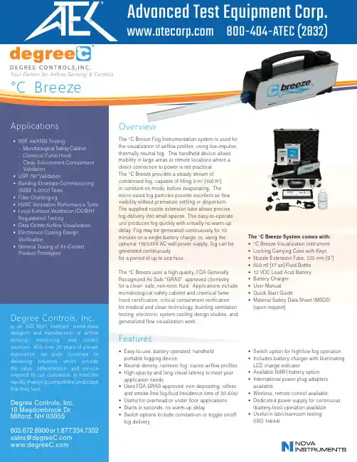
OverviewThe °C Breeze Fog Instrumentation system is used for the visualization of airflow profiles, using low-impulse, thermally neutral fog. This handheld device allowsmobility in large areas or remote locations where a direct connection to power is not practical. The °C Breeze provides a steady stream of condensed fog, capable of filling 3 m 3 [100 ft 3] in constant-on mode, before evaporating. The micro-sized fog particles provide excellent air flow visibility without premature settling or dispersion. The supplied nozzle extension tube allows precise fog delivery into small spaces. This easy-to-operate unit produces fog quickly with virtually no warm-up delay. Fog may be generated continuously for 10 minutes on a single battery charge, or, using the optional 110/230V AC wall power supply, fog can be generated continuouslyfor a period of up to one hour.The °C Breeze uses a high quality, FDA Generally Recognized As Safe “GRAS”, approved chemistry for a clean, safe, non-toxic fluid. Applications include microbiological safety cabinet and chemical fume hood certification, critical containment verification for medical and clean technology, building ventilation testing, electronic system cooling design studies, and generalized flow visualization work.ValidationYour Partner for Airflow Sensing & Controls°C BreezeISO-9001 certified, world-class and manufacturer of airflow monitoring, and control we pride ourselves on solutions which provide differentiation, and service or 1.877.334.7332*****************Features•Easy-to-use, battery operated, handheld portable fogging device•Neutral density, nontoxic fog, traces airflow profiles •High opacity and long visual latency to meet your application needs•Uses FDA GRAS approved, non-depositing, oilless and smoke-free fog fluid (residence time of 30-60s)•Useful for overhead or under floor applications •Starts in seconds, no warm-up delay•Switch options include constant-on or toggle on/off fog deliveryThe °C Breeze System comes with:•°C Breeze Visualization Instrument •Locking Carrying Case with Keys •Nozzle Extension Tube, 225 mm [9”]•500 ml [17 oz] Fluid Bottle •12 VDC Lead Acid Battery •Battery Charger •User Manual•Quick Start Guide•Material Safety Data Sheet (MSDS)[upon request]•Switch option for high/low fog operation •Includes battery charger with illuminating LED charge indicator•Available NiMH battery option •International power plug adapters available•Wireless, remote control available•Dedicated power supply for continuous (battery-less) operation available •Useful in lab/cleanroom testing (ISO 14644)Remote Control Operation Dedicated Power Supply Airflow T ool Set。
附录A
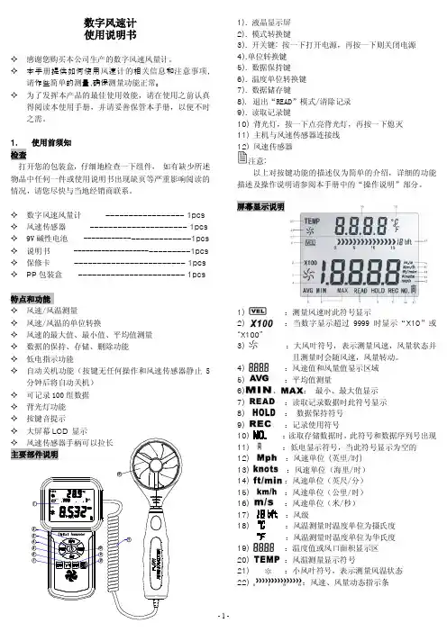
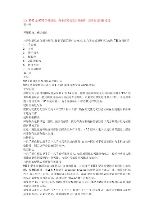
说明
说明适用于无通知的变化
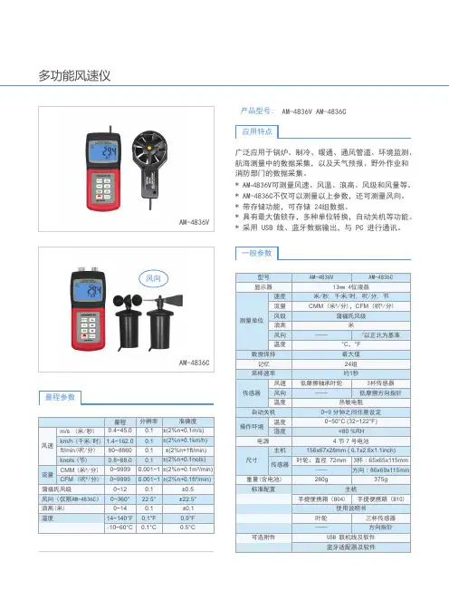
风速:
范围:0~4000英尺/每分钟(0~20米/秒)
精度1&2:±5%或±5英尺/每分钟(±0.025米/秒)两者都可为大值
分辨值:1英尺/每分钟(0.01米/秒)
温度:
范围:0~200°F(-18~93℃)
精度3:±0.5°F(±0.3℃)
分辨值:0.1°F(0.1℃)
仪器温度范围:
操作(电子):40~113°F(5~45℃)
操作(探头)0~200°F(-18~93℃)
保存:-4~140°F(-20~60℃)
仪器操作条件:
高度4000米以下
相对湿度80%以下,无凝结水
污染等级1符合IEC664
瞬时电压超过电压级别Ⅱ
仪表外尺寸:
3.3英寸×7.0英寸×1.8英寸(8.4cm×17.8cm×
4.4cm)
仪表重量:
含电池重量:0.6lbs(0.27千克)
电源配置:
4节AA电池(包含)
1温度补偿超过40~150°F(5~65℃)的温度范围。
2风速从0.15m/s到20m/s中,±3.0%或±3英寸/分钟(±0.015m/s)精度值,两者都可为最大值。
3仪器在77°F(25℃)的精确度,再加上仪器所处环境0.05°F/°F(0.03℃/℃)不确定度。
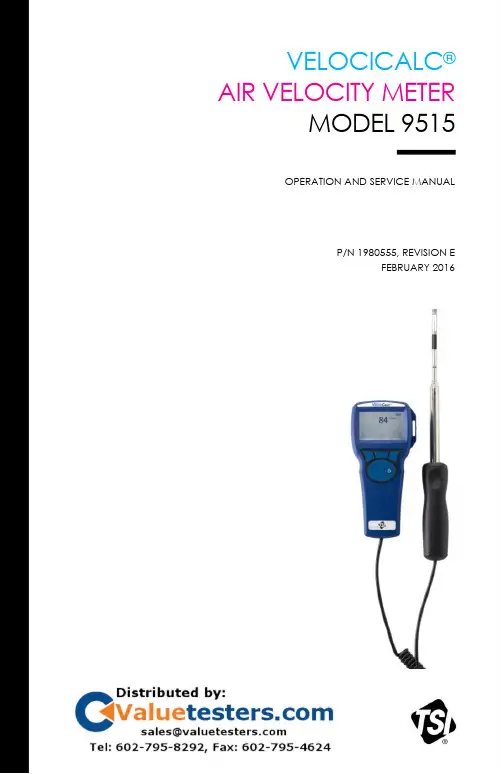
VELOCICALC®AIR VELOCITY METERMODEL 9515OPERATION AND SERVICE MANUALP/N 1980555, REVISION EFEBRUARY 2016CopyrightTSI Incorporated / 2007–2016 / All rights reserved.AddressTSI Incorporated / 500 Cardigan Road / Shoreview, MN 55126 / USAFax No.(651) 490-3824LIMITATION OF WARRANTY AND LIABILITY (effective February 2015)(For country-specific terms and conditions outside of the USA, please visit .) Seller warrants the goods, excluding software, sold hereunder, under normal use and service as described in the operator's manual, to be free from defects in workmanship and material for 24 months, or if less, the length of time specified in the operator's manual, from the date of shipment to the customer. This warranty period is inclusive of any statutory warranty. This limited warranty is subject to the following exclusions and exceptions: a. Hot-wire or hot-film sensors used with research anemometers, and certain othercomponents when indicated in specifications, are warranted for 90 days from the date of shipment;b. Pumps are warranted for hours of operation as set forth in product or operator’smanuals;c. Parts repaired or replaced as a result of repair services are warranted to be free fromdefects in workmanship and material, under normal use, for 90 days from the date of shipment;d. Seller does not provide any warranty on finished goods manufactured by others or onany fuses, batteries or other consumable materials. Only the original manufacturer's warranty applies;e. This warranty does not cover calibration requirements, and seller warrants only that theinstrument or product is properly calibrated at the time of its manufacture. Instruments returned for calibration are not covered by this warranty;f. This warranty is VOID if the instrument is opened by anyone other than a factoryauthorized service center with the one exception where requirements set forth in the manual allow an operator to replace consumables or perform recommended cleaning;g. This warranty is VOID if the product has been misused, neglected, subjected toaccidental or intentional damage, or is not properly installed, maintained, or cleaned according to the requirements of the manual. Unless specifically authorized in aseparate writing by Seller, Seller makes no warranty with respect to, and shall have no liability in connection with, goods which are incorporated into other products orequipment, or which are modified by any person other than Seller.The foregoing is IN LIEU OF all other warranties and is subject to the LIMITATIONS stated herein. NO OTHER EXPRESS OR IMPLIED WARRANTY OF FITNESS FOR PARTICULAR PURPOSE OR MERCHANTABILITY IS MADE. WITH RESPECT TO SELLER’S BREACH OF THE IMPLIED WARRA NTY AGAINST INFRINGEMENT, SAID WARRANTY IS LIMITED TO CLAIMS OF DIRECT INFRINGEMENT AND EXCLUDES CLAIMS OF CONTRIBUTORY OR INDUCED INFRINGEMENTS. BUYER’S EXCLUSIVE REMEDY SHALL BE THE RETURN OF THE PURCHASE PRICE DISCOUNTED FOR REASONABLE WEAR AND TEAR OR AT SELLER’S OPTION REPLACEMENT OF THE GOODS WITH NON-INFRINGING GOODS.TO THE EXTENT PERMITTED BY LAW, THE EXCLUSIVE REMEDY OF THE USER OR BUYER, AND THE LIMIT OF SELLER'S LIABILITY FOR ANY AND ALL LOSSES, INJURIES, OR DAMAGES CONCERNING THE GOODS (INCLUDING CLAIMS BASED ON CONTRACT, NEGLIGENCE, TORT, STRICT LIABILITY OR OTHERWISE) SHALL BE THE RETURN OF GOODS TO SELLER AND THE REFUND OF THE PURCHASE PRICE, OR, AT THE OPTION OF SELLER, THE REPAIR OR REPLACEMENT OF THE GOODS. IN THE CASE OF SOFTWARE, SELLER WILL REPAIR OR REPLACE DEFECTIVE SOFTWARE OR IF UNABLE TO DO SO, WILL REFUND THE PURCHASE PRICE OF THE SOFTWARE. IN NO EVENT SHALL SELLER BE LIABLE FOR LOST PROFITS,BUSINESS INTERRUPTION, OR ANY SPECIAL, INDIRECT, CONSEQUENTIAL OR INCIDENTAL DAMAGES. SELLER SHALL NOT BE RESPONSIBLE FOR INSTALLATION, DISMANTLING OR REINSTALLATION COSTS OR CHARGES. No Action, regardless of form, may be brought against Seller more than 12 months after a cause of action has accrued. The goods returned under warranty to Seller's factory shall be at Buyer's risk of loss, and will be returned, if at all, at Seller's risk of loss.Buyer and all users are deemed to have accepted this LIMITATION OF WARRANTY AND LIABILITY, which contains the complete and exclusive limited warranty of Seller. This LIMITATION OF WARRANTY AND LIABILITY may not be amended, modified or its terms waived, except by writing signed by an Officer of Seller.Service PolicyKnowing that inoperative or defective instruments are as detrimental to TSI as they are to our customers, our service policy is designed to give prompt attention to any problems. If any malfunction is discovered, please contact your nearest sales office or representative, or call TSI's Customer Service department at (800) 874-2811 (USA) or (001 651) 490-2811 (International) or visit .CONTENTSCHAPTER 1 UNPACKING AND PARTS IDENTIFICATION (1)CHAPTER 2 SETTING-UP (3)Supplying Power to the Model 9515 VelociCalc Air VelocityMeter (3)Installing the Batteries (3)Using The Telescoping Probe (3)Extending The Probe (3)Retracting The Probe (3)CHAPTER 3 OPERATION (5)Keypad Functions (5)CHAPTER 4 MAINTENANCE (7)Recalibration (7)Cases (7)Storage (7)CHAPTER 5 TROUBLESHOOTING (9)APPENDIX A SPECIFICATIONS (11)iii(This page intentionally left blank)Chapter 1Carefully unpack the instrument and accessories from the shipping container. Check the individual parts against the list of components below. If anything is missing or damaged, notify TSI immediately.1. Carrying case2. Instrument1(This page intentionally left blank)Chapter 1 2Chapter 2Supplying Power to the Model 9515 VelociCalc Air Velocity Meter The Model 9515 is powered with four size AA batteries.Installing the BatteriesInsert four AA batteries as indicated by the diagram located onthe inside of the battery compartment. The Model 9515 isdesigned to operate with either alkaline or NiMH rechargeablebatteries, although it will not recharge NiMH batteries. Battery life will be shorter if NiMH batteries are used. Carbon-zinc batteries are not recommended because of the danger of battery acidleakage.Using the Telescoping ProbeThe telescoping probe contains the velocity and temperature sensors. When using the probe, make sure the sensor window is fully exposed and the orientation dimple is facing upstream.Extending the ProbeTo extend the probe, hold the handle in one hand while pulling on the probe tip with the other hand. Do not hold the cable whileextending the probe as this prevents the probe from extending.Retracting the ProbeTo retract the probe, hold the handle in one hand while pullinggently on the probe cable with the other hand.3(This page intentionally left blank)4 Chapter 2Chapter 3Keypad Functions5(This page intentionally left blank)6 Chapter 3Chapter 4The Model 9515 requires very little maintenance to keep it performing well.RecalibrationTo maintain a high degree of accuracy in your measurements, we recommend that you return your Model 9515 to TSI for annual recalibration. Please contact one of TSI’s offices or your local distributor to make service arrangements and to receive a Return Material Authorization (RMA) number. To fill out an online RMA form, visit TSI’s website at .CasesIf the instrument case or storage case needs cleaning, wipe it off with a soft cloth and isopropyl alcohol or a mild detergent. Never immerse the Model 9515. If the enclosure of the Model 9515 becomes broken, it must be replaced immediately to prevent access to hazardous voltage.StorageRemove the batteries when storing the unit for more than one month to prevent damage due to battery leakage.7(This page intentionally left blank)8 Chapter 4Chapter 5Table 5-1 lists the symptoms, possible causes, and recommended solutions for common problems encountered with the Model 9515. If your symptom is not listed, or if none of the solutions solves your problem, please contact TSI.Table 5-1: Troubleshooting the VelociCalc Model 95159(This page intentionally left blank)10 Chapter 5Appendix ASpecifications are subject to change without notice.Velocity:Range: 0 to 4000 ft/min (0 to 20 m/s)Accuracy1&2: ±5% of reading or ±5 ft/min (±0.025 m/s),whichever is greaterResolution: 1 ft/min (0.01 m/s)Temperature:Range: 0 to 200°F (-18 to 93°C)Accuracy3: ±0.5°F (±0.3°C)Resolution: 0.1°F (0.1°C)Instrument Temperature Range:Operating (Electronics): 40 to 113°F (5 to 45°C)Operating (Probe): 0 to 200°F (-18 to 93°C)Storage: -4 to 140°F (-20 to 60°C)Instrument Operating Conditions:Altitude up to 4000 metersRelative humidity up to 80% RH, non-condensingPollution degree 1 in accordance with IEC 664Transient over voltage category IIExternal Meter Dimensions:3.3 in. ⨯ 7.0 in. ⨯ 1.8 in. (8.4 cm ⨯ 17.8 cm ⨯4.4 cm)Meter Weight:Weight with batteries: 0.6 lbs (0.27 kg)Power Requirements:Four AA-size batteries (included)1Temperature compensated over an air temperature range of 40 to 150°F (5 to65°C).2The accuracy statement of ±5.0% of reading or ±5 ft/min (±0.025 m/s), whichever is greater, begins at 30 ft/min through 4000 ft/min (0.15 m/s through 20 m/s).3Accuracy with instrument case at 77°F (25°C), add uncertainty of 0.05°F/°F(0.03°C/°C) for change in instrument temperature.11(This page intentionally left blank)12 Appendix ATSI Incorporated– Visit our website for more information.USA Tel: +1 800 874 2811 UK Tel: +44 149 4 459200 France Tel: +33 1 41 19 21 99 Germany Tel: +49 241 523030India Tel: +91 80 67877200 China Tel: +86 10 8219 7688 Singapore Tel: +65 6595 6388P/N 1980555 Rev E ©2016 TSI Incorporated Printed in U.S.A. *1980555*。
tsi9545风速仪工作原理一、引言TSI 9545 风速仪是一种用于测量风速的仪器,广泛应用于气象、环境监测、能源等领域。
本文将介绍 TSI 9545 风速仪的工作原理。
二、基本原理TSI 9545 风速仪采用了热线式风速传感器,其基本原理是利用热线受风冷却的特性来测量风速。
当空气流过热线时,由于空气的流动会带走热线上的热量,导致热线温度下降。
通过测量热线温度变化,可以计算出空气的流速。
三、详细原理1. 热线传感器热线传感器是 TSI 9545 风速仪中最核心的部件之一。
它由两个金属丝组成,一个作为加热丝,一个作为测量丝。
加热丝通电后发生加热,并使周围空气温度升高;而测量丝则处于静止状态。
当空气流过时,由于空气具有较好的导热性,在流经测量丝时会带走一定的热量,导致测量丝温度下降。
通过测量测量丝温度变化,可以得到空气的流速。
2. 电路TSI 9545 风速仪的电路主要包括恒流源、放大器、滤波器、模数转换器等部分。
其中,恒流源用于提供一定的电流给热线传感器加热丝;放大器用于放大测量丝的信号;滤波器用于去除杂散信号和噪声;模数转换器则将模拟信号转换为数字信号输出。
3. 算法根据热线传感器的原理,可以得到以下公式:Q = k * (T1 - T2)其中,Q 表示空气流过热线带走的热量,k 表示比例常数,T1 和 T2分别表示加热丝和测量丝的温度。
通过对公式进行变形,可以得到以下计算公式:v = (Q / k) / A其中,v 表示空气流速,A 表示传感器截面积。
通过对公式进行进一步简化和优化,可以得到 TSI 9545 风速仪所采用的算法。
四、总结本文介绍了 TSI 9545 风速仪的工作原理。
通过对热线传感器、电路和算法等方面进行详细的分析,可以更好地理解 TSI 9545 风速仪的工作原理和测量原理。
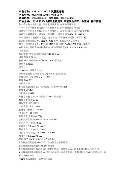
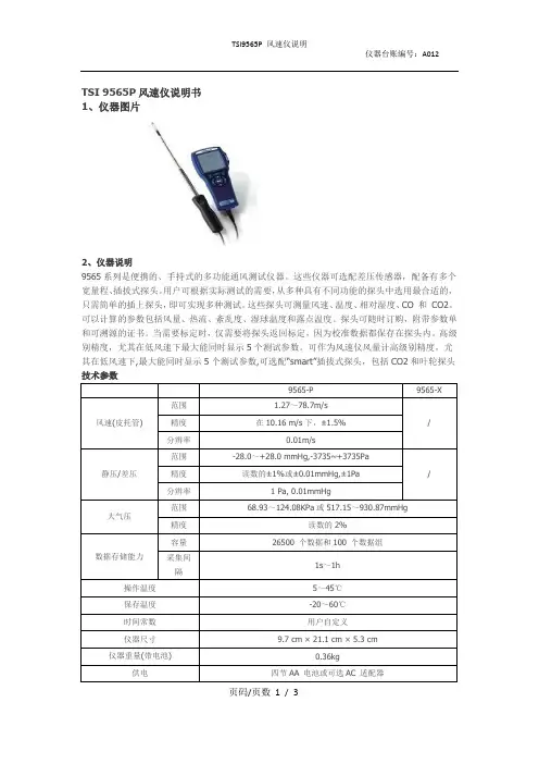
产品名称:VELOCICALC® 风量流速表产品型号:9535/9535-A/9545/9545-A型销售热线:1326-007-2458 商务QQ:474-556-186产品介绍:9535 和9545 型风量流速表风速表是具有一台普通操作简便仪表价位的多功能仪表。
该仪表可以使用精密的风速测量一个具有多个传感器的探头同时测量和记同时测量温度和风速录通空气中的多个参数。
这两个型号的仪最多能同时显示三个测量参数器都可以测量风速、温度和计算风量。
可测量湿度(9545 和9545-A)9545 型还可以测量相对湿度,并计算出可计算体积流量,在实际/ 标露点温度和湿球温度。
9535 和9535-A 型准状况风速之间切换具有可伸缩的直探头。
9545 和9545-A具包括LogDat2TM 数据下载软件有可伸缩、可折弯的铰接式探头探头可以折弯 ( 9 5 3 5 - A 和9545-A)技术参数:检测参数/ 型号 9535 9535-A 9545 9545-A风速范围 0∼30 m/s精度1&2 读数的± 3% 或± 0.015m/s,较大值分辨率 0.01m/s风管尺寸1∼635cm,增量为0.1cm体积流量量程实际量程是风速和风管尺寸的函数温度范围 -17.8∼93.3℃ 14∼140℃精度3 ± 0.3℃分辨率 0.1℃相对湿度 (湿球温度、露点温度) 范围 / 0∼95%RH精度4 ± 3%RH分辨率 0.1%RH数据存储能力 12700 个数据和100 个数据组数据采集间隔 1s∼1h时间常数用户自定义工作温度主机 5∼45℃传感器 -18∼93℃ -10∼60℃储存温度 -20∼60℃仪器重量(带电池) 0.27kg主机外部尺寸 8.4 cm × 17.8 cm × 4.4 cm探头尺寸长度 101.6 cm顶部直径 7.0 mm / 7.0 mm /基座直径 13.0 mm 13.0 mm可折弯探头长度 / 16.26 cm / 16.26 cm尺寸直径 9.5 mm 9.5 mm供电四节AA 电池或可选AC 适配器1 当温度范围超过5~65℃后,风速测量值需要修正;2 该精度指测量0.15~30m/s 时的精度3 该精度指测量环境温度为25℃时的精度,温度变化后,需要增加0.03℃/℃的补偿4 该精度指测量环境温度为25℃时的精度,温度变化后,需要增加0.2% RH/℃的补偿,包括了1% 的滞后TSI 便携式仪器新、老型号对照表老型号新型号新型号特点数据存储热式风速计 8345 9535 T,V, 流量, 标况/ 现况手动8346 9535-A T,V, 流量, 标况/ 现况手动8347/8384 9545 T,V, RH,流量,湿球温度露点, 标况/ 现况手动,自动8347A/8384A 9545-A T,V, RH,流量,湿球温度露点, 标况/ 现况手动,自动T= 温度;P= 压力(静压/ 差压);V= 风速;RH= 相对湿度。
Instruction Manual32, rue Edouard Martel BP55F42009 – Saint Étienne Cedex 2 E-mail:***************Tel : 04 77 59 01 01 Fax : 04 77 57 23 23 Web : www.sefram.frCONTENTSTITLE PAGE1. General Description (1)2. Safety Information (1)3. Application (1)4. Features (1)5. Specifications (2)6. Symbol Definition and Button Location (3)7. Button Instructions (6)7.1 Power ON/OFF/ Backlight button (6)7.2 Data-Hold button (6)7.3 MAX/MIN/AVG button (6)7.4 Flow button (6)7.5 Unit button (7)7.6 °C /°F Button (7)8. Operating Instructions (7)8.1 Setup Options (7)8.2 Menu Item (7)8.3 Menu Description (9)8.3.1 Set Duct Area (9)8.3.2 Set Absolute pressure (9)8.3.3 Set auto power off time (9)9. Measuring Procedure (10)9.1 Extending the Probe (10)9.2 Using the Telescoping Probe (10)10. Power Preparation (10)10.1 Battery Replacement (10)10.2 AC Adapter Connection (11)11. Maintenance (11)Thank you for choosing our Hot Wire Anemometer. To ensure the safety and the best performance of this instrument, we recommend you to read and follow the manual carefully before operation.Read the following safety information carefully before attempting to operate or service the meter. Use the meter only as specified in this manual; otherwise, the protection provided by the meter may be impaired.✽✽DANGER✽✽The meter is not designed for use in gas mixtures other than air. DO NOT use the unit with corrosive or other dangerous or explosive gas mixtures.ENVIRONMENT CONDITIONS▪Altitude up to 2000 meters▪Relatively humidity: 90% max▪Operation ambient temperature: 0°C to 50°CMAINTENANCE & CLEARINGcovered in this manual should only be performed by qualified▪Measuring volumetric flow rates or flow velocities in ducts▪Measuring the temperature and humidity of flows▪HVAC system performance▪Fast response.▪Telescoping hot wire probe.▪Air flow measure: CMM、CFM.▪Air velocity measurement:m/s, km/hr, ft/min, MPH, Knots & build in temperature ºC / ºF, humidity RH.▪Large LCD display with backlight.▪Min/Max/Avg & 2/3Vmax function.▪Data Hold function.▪With USB interface supply power.▪Battery Life indicator.▪Adjustable auto power off timer.▪Air velocity compensation in atmospheric pressure.▪Tilt Stand.Velocity Probe Range: 0 to 30 m/s(0 to 6000 ft/min)0 to 999900 m3/min(ft3/min)-20 ºC ~60 ºC (-4 ºF ~140 ºC)0~100%RHResolution: 0.01 m/s(1 ft/min)0.001 m3/min(ft3/min)0.1 ºC /ºF0.1%RHAccuracy: (at 23 ºC ±5 ºC <80%RH)±3% of reading ± 1%FS (0 to 20 m/s)±5% of reading ± 1%FS (20 to 30 m/s)±0.8 ºC (±1.5 ºF)±3.5%RH at (20% ~ 80%RH)±5%RH at (0% ~ 100%RH)Warm Up Time: 5 secondsSample Rate 2 time per secondBattery: 9V Alkaline batteryUSB Power Adapter: DC 5V 0.5ABattery Lifetime Approx. 10 hours (alkaline battery)Operation TemperatureMeter / Probe : 0°C to 50°C (32°F to 122°F) / -20°C to 60°C (-4°F to 140°F) Operation Humidity: 10 to 90%RH (no condensing)Storage Temperature: -20°C to 60°C (-4°F to 140°F)Storage Humidity: 10 to 75%RHDimensions: Meter:185mm(L) × 65mm(W) × 36mm(H) /7.28 inches(L) × 2.56 inches(W) × 1.41 inches(H)Wire length: 185 cmProbe length: 87 cmProbe diameter of tip: 9.0 mmProbe diameter of base:16.0 mmWeight: Approx.412 g(included battery and probe): Battery condition indicator : Air velocity indicator: Air velocity reading: Air velocity measurement units: Air flow indicator: Air flow 2/3V Maximum indication: Air flow reading: Multiply reading by ten: Multiply reading by one hundred: Multiply reading by one thousand: Air flow measurement units: Area setting units: Duct Area indication: Round Duct diameter dimension indication: Rectangle Duct X and Y dimension indication: Pressure indication: Temperature reading: Temperature measurement units: Relative Humidity reading: Relative Humidity measurement units: Data hold indication○,1 Sensor Probe (Measurement direction) ○,2 Protective Shutter ○,3 Telescoping Probe○,4 Display Screen ○,5 Power ON/OFF and Back Light Button ○,6 MAX MIN AVG Button ○,7 FLOW MAX 2/3VMAX AVG Button ○,8 DATA HOLD Button ○,9 Unit Button○,10 °C/°F Button ○,11 Power Source Interface(micro USB type) ○,12 Tilt Stand ○,13 Battery Compartment7.1 Power ON/OFF/ Backlight Button:Press the button to turn on the meter and then press the to turn on the LD backlight.Press again to turn off backlight. This makes it easier to read in dark environment. The backlight will be automatically turned off after 30 seconds to save battery power. Press and holdbutton for 3 seconds to turn off.There is a 5 second count down as the meter warms up. 7.2 Data-Hold Button :Press button to freeze the data shown on the LCD screen. Press it again to exit Data-Hold mode.Note: When the unit is in the Data-Hold mode, / / / buttons are disabled.7.3 MAX/MIN/AVG Button:Under this mode, the unit simultaneously monitors and stores the maximum, minimum and average value in the memory. The unit will keep updating/refreshing the data.To start:(1) Press button. “ ” symbol lights up on LCD, the reading shows the maximum data.(2) Press button again to show minimum data; the “” symbol lights up on LCD.(3) Press button again to show average data; the “” symbol lights up on LCD.(4) Press button again, the “ , and” symbol blinks together, the readingsshows real time data.To exit MAX/MIN/A VG mode:Press and hold button for 2 seconds to exit MAX/MIN/AVG mode.7.4 FLOW Button :AIR FLOW = (AIR VELOCITY) x (AREA)Under this mode, the unit simultaneously monitors and stores the maximum, 2/3V maximum and average value in the Air flow. The unit will keep updating/refreshing the data.To start:(1) Press button. “ ” symbol lights up on LCD, the reading shows the maximum data.(2) Press button again to show two-third Velocity maximum data; the “ ” symbollights up on LCD.(3) Press button again to show average data; the “” symbol lights up on LCD.(4) Press button again, the “ , and”symbol blinks together, thereadings shows real time data.To exit MAX/2/3V MAX/A VG mode:Press and hold button for 2 seconds to exit MAX/2/3VMAX/AVG mode.7.5 Unit Button:Press to select the desired unit of air velocity.7.6 °C/°F Button:Press to select the desired unit of temperature.8.1 Setup Options:(1) Power off the meter and then press the and button for 3 seconds to enter setupmode. Press to exit anytime.(2) Press the button to enter the setting option.(3) Press the button to save changes and move to next setting option.8.2 Menu Item:(1) Fig.1Setup mode.(2) Fig.2Set Area.(3) Fig.3 Set Round Duct diameter dimension.(4) Fig.4 Set Rectangle Duct X dimension.(5) Fig.5 Set Rectangle Duct Y dimension.(6) Fig.6 Set absolute pressure.(7) Fig.7 Set auto power off time.8.3 Menu Description:8.3.1 Set Duct AreaThere are 3 types : Duct Area (AREA), Round Duct (○), Rectangle Duct ( ),(1) Press the button to select the type and then press the button to confirm yourchoice.(2) If duct area is chosen, the “AREA” symbol will displayed. (Fig.2)Press the or button to set the size from 1 cm2 to 40 m2 (0.001 to 430.0 ft2).Press the button to store the value.If round duct is chosen, the (○) symbol will displayed. (Fig.3)Press the or button to set the size (diameter) from 1 to 635 cm (0.4 to 250 in).Press the button to store the value.If rectangle duct is chosen, the “X” symbol will displayed. (Fig.4)Press the or button to set the size of the duct ,then press the button to store the value and advance to the next dimension, the “Y” symbol will displayed.Press the or button to set the size of the duct.Press the button to store the value.8.3.2 Set Absolute pressurePress the or button to set absolute pressure from 100 to 2000 HPA (59 to 2.95 inHg)and then press the button to store the value.8.3.3 Set auto power off time:(1) Press the or button to select auto power off option 10, 30 minutes, 1, 2, 4, 8 hours,or off. (see Fig.8 or Fig.9)Fig.8 Fig.99.1 Extending the ProbeOpen the protective shutter and then extend the probe. Do not hold the cablewhile extending the probe.9.2 Using the telescoping ProbePut the probe in the right position and make sure that the sensor window isfully exposed and is facing upstream✽ If in the right direction, the user will see the white-arrow marking asfollowing figure10.1 Battery Replacement: (1) When the battery voltage drops below proper operation range, the symbol will blink on the LCD display and the battery needs to be replaced.(2) Before replacing the battery, power off the meter.Open the cover of the battery cabinet. Replace the old batteries with new 9V alkaline battery (Carbon-zinc batteries are not recommended).(3) Close the battery cabinet cover.9V Alkaline Battery X 1pc10.2 AC Adapter Connection:When the AC adapter is used, insert the plugs of the adapter into the USB connector on the side panel.Note:When the AC adapter is connected while battery is inserted, the unit will be powered from the adapter (the AC adapter has priority).Clean the device and the window of the display with a clean, lint-free, antistatic and dry cleaning。
TRUST. SCIENCE. INNOVATION.V ELOCI C ALC ®Thermal AnemometersModels 9535,9535-A,9545 and 9545-AThe Models 9535 and 9545 thermal anemometers are likehaving multiple meters—for the price of just one.These meters simultaneously measure and data log several ventilation parameters using a single probe with multiple sensors.Both models measure velocity,temperature and calculate flow.TheModel 9545 also measures relative humidity,and calculates dew point,and wet bulb temperature.Models 9535 and 9545have telescopic straight probes; Models 9535-A and 9545-A have telescopic articulated probes.Ventilation Test InstrumentsE N E R G Y A N D C O MF O R T0.6 lbs. (0.27 kg)Meter Probe Dimensions Probe Length 40 in.(101.6 cm)Probe Diameter of Tip0.28 in.(7.0 mm)Probe Diameter of Base0.51 in.(13.0 mm)Articulating Probe Dimensions Articulating Section Length6.4 in.(16.26 cm)Diameter of Articulating Knuckle0.38 in.(9.5 mm)Power RequirementsFour AA-size batteries or AC adapterE N E R G Y A N D C O MF O R TSpecificationsV ELOCI C ALC Models 9535 and 9545Velocity Range 0 to 6,000 ft/min (0 to 30 m/s)Accuracy 1&2±3% of reading or ±3 ft/min (±0.015 m/s),whichever is greater Resolution 1 ft/min (0.01 m/s)Duct Size Dimensions1 to 250 inches in increments of 0.1 in.(1 to 635 cm in increments of 0.1 cm)Volumetric Flow Rate Range Actual range is a function of velocity,and ductsize TemperatureRange (9535 and 9535-A)0 to 200 °F (-17.8 to 93.3°C)Range (9545 and 9545-A)14 to 140°F (-10 to 60°C)Accuracy 3±0.5°F (±0.3°C)Resolution 0.1°F (0.1°C)Relative Humidity (9545 only)Range 0 to 95% RHAccuracy 4±3% RH Range 0.1% RHInstrument Temperature Range Operating (Electronics)40 to 113°F (5 to 45°C)Model 9535 Operating (Probe)0 to 200°F (-18 to 93°C)Model 9545 Operating (Probe)14 to 140°F (-10 to 60°C)Storage -4 to 140°F (-20 to 60°C)Data Storage Capabilities Range 12,700+ samples and 100 test IDs Logging Interval 1 second to 1 hour Time Constant User selectableExternal Meter Dimensions3.3 in. x 7.0 in. x 1.8 in. (8.4 cm x 17.8 cm x4.4 cm)Ventilation Test InstrumentsP/N 2980569 Rev A Copyright © 2007 by TSI Incorporated Printed in U.S.A.TRUST. SCIENCE. INNOVATION.Temperature compensated over an air temperature range of 40 to 150°F (5 to 65°C).The accuracy statement begins at 30 ft/min through 6,000 ft/min (0.15 m/s through 30 m/s).Accuracy with instrument case at 77°F (25°C),add uncertainty of 0.05°F/°F (0.03°C/°C) for change in instrument temperature.Accuracy with probe at 77°F (25°C).Add uncertainty of 0.1% RH/°F (0.2% RH/°C) for change in probe temperature.Includes 1% hysteresis.Specifications are subject to change without notice.。
多参数通风表TSI9555简介多参数通风表TSI9555是一种用于室内空气质量评估和空调系统调节的工具,能够测量CO2浓度、空气温度、相对湿度以及空气流速等参数。
该仪器便携轻便,操作简便,被广泛应用于学校、办公室、实验室、医院等公共场所以及工业生产现场等各种场合。
功能特点1、多参数测量多参数通风表TSI9555可同时测量CO2浓度、空气温度、相对湿度、空气流速等多项参数,并对测量结果进行处理和统计。
通过对这些参数的监测和分析,可以得出室内空气质量的等级和空调系统是否工作正常等关键信息。
2、自动储存数据该仪器具备自动储存数据的功能,可以持续记录一定时间段内的数据变化,并将数据以表格形式保存,方便后续分析和比对。
3、大屏幕显示多参数通风表TSI9555配备了大屏幕显示设计,可以实时显示测量数据以及相关参数。
此外,该多参数通风表还可以显示最大、最小、平均值等数据,并自动进行曲线图绘制,使得用户更加直观地了解室内空气质量的变化趋势。
4、可编程自动采样该仪器还具有可编程自动采样功能,可以根据用户自定义的采样间隔对空气参数进行监测和分析,极大地提高了空气质量监测的效率和精确度。
使用方法1、开机在使用多参数通风表TSI9555前,请确保仪器已充电并插好电源。
按下电源键开机,并在开机界面中对相关参数进行设置。
2、参数测量将仪器插入需要监测的室内环境中,等待仪器自动测量并实时显示相关参数。
3、存储数据可通过设置自动储存数据的功能,将数据以表格形式保存,并可以通过电脑或其他设备进行查看分析和比对。
4、可编程自动采样对于需要连续监测的场合,可以通过设置可编程自动采样功能,根据自定义采样间隔进行数据采集和记录。
结语多参数通风表TSI9555作为一种功能齐全的室内空气质量监测工具,具有种种优势和特点。
企业和公共场所可以使用该仪器对室内空气质量进行监测和管理,以创建一个更健康、更舒适的室内环境。
TSI9545风速仪工作原理介绍TSI9545风速仪是一种常用的风速测量工具,广泛应用于气象学、环境科学、建筑工程等领域。
本文将详细介绍TSI9545风速仪的工作原理及其相关知识。
什么是TSI9545风速仪TSI9545风速仪是一种用于测量风速的仪器,主要由风速传感器、控制电路、显示屏等组成。
其主要功能是测量空气流过传感器的速度,并将结果显示在仪表盘上。
TSI9545风速仪工作原理TSI9545风速仪的工作原理涉及到风速传感器的基本原理和测量原理。
风速传感器的基本原理风速传感器是TSI9545风速仪中的核心部件,它主要通过测量风流对传感器表面的冷却作用来间接测量风速。
传感器表面通常包裹着一个薄膜,当风吹过薄膜时,风流会导致薄膜表面的温度下降。
传感器内部的电路可以感知到温度的变化,并将其转换为电信号。
TSI9545风速仪的测量原理TSI9545风速仪的测量原理基于热线风速传感器技术。
传感器表面有一个加热丝,当风吹过时,传感器表面的冷却程度与风速呈正相关,冷却越大代表风速越高。
通过测量传感器表面温度的变化,可以计算出风速的大小。
TSI9545风速仪的使用方法TSI9545风速仪的使用方法相对简单,只需要将传感器部分对准风的方向,然后观察仪表盘显示即可。
使用步骤1.打开TSI9545风速仪的开关。
2.等待仪器启动完成,此时仪表盘会显示当前的风速值。
3.将传感器部分对准风的方向,确保风流正常地吹过传感器表面。
4.观察仪表盘显示,即可获取当前的风速数值。
TSI9545风速仪的应用领域TSI9545风速仪在多个领域有着广泛的应用,下面将列举一些应用领域。
气象学TSI9545风速仪可以用于测量和记录气象站点的风速信息,帮助气象学家进行天气预测和研究。
环境科学在环境监测中,TSI9545风速仪可以帮助科学家测量和分析空气流动的情况,进而了解环境中的污染物扩散情况。
建筑工程在建筑工程中,TSI9545风速仪被用于测量微颗粒悬浮物的输送速率,以便设计和改进空气净化系统。