汽车犀牛建模教程
- 格式:docx
- 大小:284.70 KB
- 文档页数:7

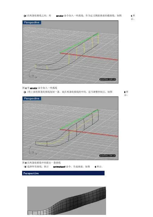
图5在两条轮廓线中间做出一条曲线(5)选择所有曲线,执行networksrf命令,生成曲面,如图6所示。
Perspective4所示。
(3)在两条轮廓线之间,用arcdir命令加入一些弧线,作为定义侧面曲面的截面线,如图图4用arcdir命令加入一些弧线5所示。
(4 )将上面的那条轮廓线复制一条,放在两条轮廓线的中间,适当调整控制点,如图在这个教学里,将简单介绍用rhino制作跑车的基本方法。
图1用rhino制作的跑车(1)在侧面视图里,绘制出侧面的两条轮廓线,如图2所示。
图2画出两条车体的轮廓线(2)在上视图里,打开两条轮廓曲线的控制点,适当调整控制点,如图2所示。
在调整控制点的同时,可以根据需要,用insertknot 命令给曲线加入控制点。
图3在上视图里面调整控制点6)用mirror命令镜象出另外半边的曲面,执行mergesf命令,将两个曲面合而为一,如图7所示。
图7用mergesf命令将两个曲面合而为(7)如图8所示,画出一序列的曲线。
PerspertivE图8画出一序列的曲线(8)执行sweep2命令,产生曲面,注意选择上一步骤画出的一序列的曲线的中间那条面的边界作为rail的路径线,然后选择出的围绕在U字形曲线的一序列的曲线作为曲面,如图9所示。
U字形的曲线和前面产生的曲cross section 的截面线,产生图9用sweep2命令产生曲面9)执行matchsrf命令,选择刚才用sweep2产生的曲面,然后再选择它下面的曲面,对话框里面,选择Tangency和Refine match 其他都不要选,如图10所示。
图10用matchsrf命令匹配两个曲面(10)在上视图里面,画出一条曲线,然后镜象出另外一边的曲线,如图11所示。
图11在上视图里面做出对称的一对曲线(11)执行trim 命令,用上一步骤产生的那对曲线来剪切车体上部的曲面,如图12所示。
PsrsijeiJlYe进行曲面匹配,在match surface图12用trim 命令剪切车体上部曲面12)在车头通风口处,画出两条直线,用 trim 命令将下面的曲面剪切出一个开口来,如图 图13在通风口处剪切出一个开口来(13)如图14所示,画出4条曲线,用networksrf 命令产生一个曲面。
犀牛汽车建模教程简介汽车建模是计算机图形学的重要应用之一,也是产品设计与开发过程中的重要环节之一。
本教程将以犀牛(Rhinoceros)软件为例,介绍汽车建模的基本流程和技巧。
1. 准备工作在开始之前,我们首先需要准备好以下工具和素材: - 犀牛软件:你可以从官网下载犀牛软件,并按照官方指引进行安装。
- 参考图:你可以从互联网上搜索到你想要建模的汽车的参考图,并保存到电脑上。
2. 导入参考图在犀牛软件中,我们需要将参考图导入到建模场景中,以便参考和绘制。
2.1 打开犀牛软件双击打开犀牛软件,启动软件。
2.2 导入参考图在软件的菜单栏中,选择“文件”->“导入”,然后选择你保存在电脑上的参考图文件,点击“打开”按钮。
参考图将会被导入到犀牛场景中。
2.3 调整参考图位置和大小在犀牛的“命令行”中输入“PictureFrame”命令,然后按照提示选择导入的参考图,接着按照需要调整参考图的位置和大小。
3. 建立基本几何体在开始绘制汽车的外观之前,我们首先需要建立一些基本几何体,以便参考和操作。
3.1 绘制车轮轮廓选择犀牛的“曲线”工具,绘制出车轮的轮廓。
可以参考参考图来确定轮廓的形状。
3.2 创建车身基础结构使用犀牛的“面”工具,根据参考图的形状,绘制出汽车的车身基础结构。
可以使用直线和曲线来绘制多边形。
3.3 创建车窗和灯光使用犀牛的“曲面”工具,根据参考图的形状,绘制出汽车的车窗和灯光。
4. 细化和调整设计在完成基本的汽车外观建模之后,我们可以对细节进行调整和优化。
4.1 平滑曲线和曲面使用犀牛的“平滑”功能,对汽车的曲线和曲面进行平滑处理,使其更加真实和光滑。
4.2 添加细节使用犀牛的“细化”功能,添加汽车的细节,如车灯、车窗的细节等。
4.3 调整比例和比例根据需要,使用犀牛的“缩放”和“旋转”功能,调整汽车的比例和角度,使其符合设计需求。
5. 渲染和导出在完成汽车建模之后,我们可以进行渲染和导出,以便进行展示和分享。
犀牛建曲面方法
1. ExtrudeCrv:在命令行里有双向的选项,输入该命令回车之后,先点击命令行里的,然后选择你要挤出的曲线。
2. ExtrudeSrf:选取一个曲面——设定距离——按Enter完成命令。
在点击命令的过程中,如需改变挤出方向或是否实体,需提前在命令中点击。
3. ExtractIsocurve:该命令可以在曲面的U/V方向上添加曲面的控制线。
输入命令后,首先点击两条曲面的路径,再点击曲面的一条边缘,完成相应的曲面建模。
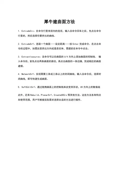
4. NetworkSrf:实现需要三条或三条以上的封闭曲线,输入该命令后,选择封闭曲线,即可快速生成曲面。
5. SoftEditSrf:通过拖拽曲面上的控制线来改变其形状,UV方向上的数值越
此外,还有Rebuild、PlanarSrf、CreateUVCrv等其他方法。
这些方法各有特点和使用范围,用户可根据实际需求选择合适的方法进行操作。
犀牛参数化建模基本操作方法犀牛软件是一种3D建模软件,使用参数化建模方法可以使得模型的形状和尺寸能够通过改变参数来灵活调整。
以下是犀牛软件中的基本参数化建模操作方法:1. 创建基本几何体:首先,在犀牛软件中选择合适的基本几何体,如球体、立方体、圆柱体等,创建一个原始模型作为基础。
2. 转换类型:通过一系列的转换操作,可以将基本几何体转换成其他复杂形状。
例如,可以使用平移、旋转、缩放等操作方法对基础几何体进行转换。
3. 使用曲线和曲面:在犀牛软件中,可以通过曲线和曲面来创建更加复杂的形状。
可以使用曲线工具绘制出所需的曲线形状,并使用曲面工具来创建曲面,并将曲线进行放样、拉伸、旋转等操作。
4. 参数化控制:在犀牛软件中,可以为模型中的各个部分添加参数,以便在后续的调整中能够灵活地改变模型的形状和尺寸。
例如,可以添加参数来控制模型的长度、宽度、高度等,通过改变参数的值来调整模型的尺寸。
5. 调整模型:通过在犀牛软件中调整参数的值,可以实时地改变模型的形状和尺寸。
可以通过鼠标拖动参数滑块或者手动输入数值来改变参数的值,从而实现模型的形状调整。
6. 添加约束:在犀牛软件中,可以添加约束来限制模型的一些属性。
例如,可以添加关系约束来确保模型的各个部分保持相对位置不变,或者添加数值约束来限制参数的范围。
7. 参数化关联:可以使用参数化关联方法来使得模型中的各个部分之间相互关联。
例如,可以通过定义参数之间的关系来实现模型中的一部分随着另一部分的变化而实时更新。
通过以上的参数化建模基本操作方法,可以在犀牛软件中灵活地进行模型的设计和调整,使得模型的形状和尺寸可以快速改变,提高了建模的效率和灵活性。
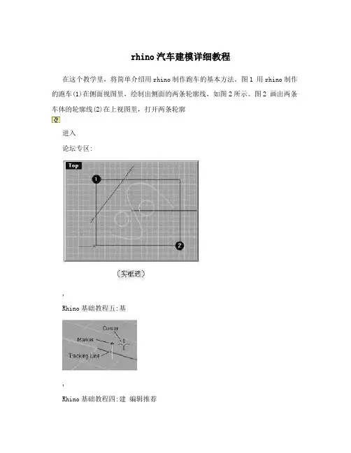
rhino汽车建模详细教程在这个教学里,将简单介绍用rhino制作跑车的基本方法。
图1 用rhino制作的跑车(1)在侧面视图里,绘制出侧面的两条轮廓线,如图2所示。
图2 画出两条车体的轮廓线(2)在上视图里,打开两条轮廓进入论坛专区:,Rhino基础教程五:基,Rhino基础教程四:建编辑推荐在这个教学里,将简单介绍用rhino制作跑车的基本方法。
图1 用rhino制作的跑车 (1)在侧面视图里,绘制出侧面的两条轮廓线,如图2所示。
图2 画出两条车体的轮廓线(2)在上视图里,打开两条轮廓曲线的控制点,适当调整控制点,如图2所示。
在调整控制点的同时,可以根据需要,用iertknot命令给曲线加入控制点。
图3 在上视图里面调整控制点(3)在两条轮廓线之间,用arcdir命令加入一些弧线,作为定义侧面曲面的截面线,如图4所示。
图4 用arcdir命令加入一些弧线(4)将上面的那条轮廓线复制一条,放在两条轮廓线的中间,适当调整控制点,如图5所示。
图5 在两条轮廓线中间做出一条曲线(5)选择所有曲线,执行networksrf命令,生成曲面,如图6所示。
图6 用networksrf命令产生曲面(6)用mirror命令镜象出另外半边的曲面,执行mergesrf命令,将两个曲面合而为一,如图7所示。
图7 用mergesrf命令将两个曲面合而为一(7)如图8所示,画出一序列的曲线。
图8 画出一序列的曲线(8)执行sweep2命令,产生曲面,注意选择上一步骤画出的一序列的曲线的中间那条U字形的曲线和前面产生的曲面的边界作为rail的路径线,然后选择出的围绕在U字形曲线的一序列的曲线作为cro section的截面线,产生曲面,如图9所示。
图9 用sweep2命令产生曲面(9)执行matchsrf命令,选择刚才用sweep2产生的曲面,然后再选择它下面的曲面,进行曲面匹配,在match surface对话框里面,选择Tangency和Refine match其他都不要选,如图10所示。
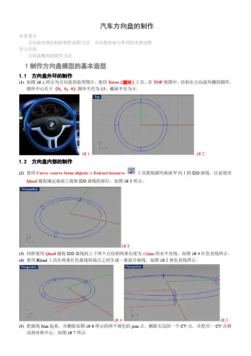
汽车方向盘的制作本章重点方向盘内部结构的制作流程方法方向盘内部与外环的光滑过渡学习目的方向盘模型的制作方法1制作方向盘模型的基本造型1.1 方向盘外环的制作(1)如图16-1所示为方向盘的造型图片。
使用Torus(圆环)工具,在TOP视图中,绘制出方向盘外圈的圆环,圆环中心位于(0,0,0)圆环半径为13,截面半径为1。
16-116-21.2 方向盘内部的制作(2)使用Curve >curve form objects > Extract lsocurve 工具提取圆环曲面V向上的ISO曲线,注意使用Quad捕捉确定曲面上提取ISO曲线的部位,如图16-3所示。
16-3(3)同样使用Quad捕捉ISO曲线的上下两个点绘制两条长度为15mm的水平直线,如图16-4红色直线所示。
(4)使用Blend工具在两条红色曲线的端点之间生成一条混合曲线,如图16-5黄色直线所示。
16-4 16-5 (5)把曲线Join起来,并删除如图16-6所示的两个黄色的join点。
删除右边的一个CV点,并把另一CV点移动到对称中心。
如图16-7所示16-616-7(6) 重建调整后的曲线为3阶曲线,13个CV 点。
再次调整曲线的CV 点为如图16-8所示16-8(7) 把编辑好的曲线以圆环的圆心为中心在另一边复制一根,如图16-9所示。
16-9(8) 利用Mid 和End 捕捉模式绘制如图16-10所示的黄色曲线。
16-10(9) 使用Sweep2工具,以黄色曲线为轨道,红色曲线为截面曲线,生成如图16-11所示的蓝色曲面。
使用工具删除所得曲面V 向上的两根ISO Curve,结果如图16-11右图所示16-11(10)使用Transform>Move UVN工具,打开曲面的控制点,把位于圆环中心附近的控制点沿着UVN适当移动,使得位于圆环中心部位的曲面略微向上凸起,注意:CV点的移动有的仅为U向,有的为V向,有的为N 向,应选择相应的CV点逐步调整。
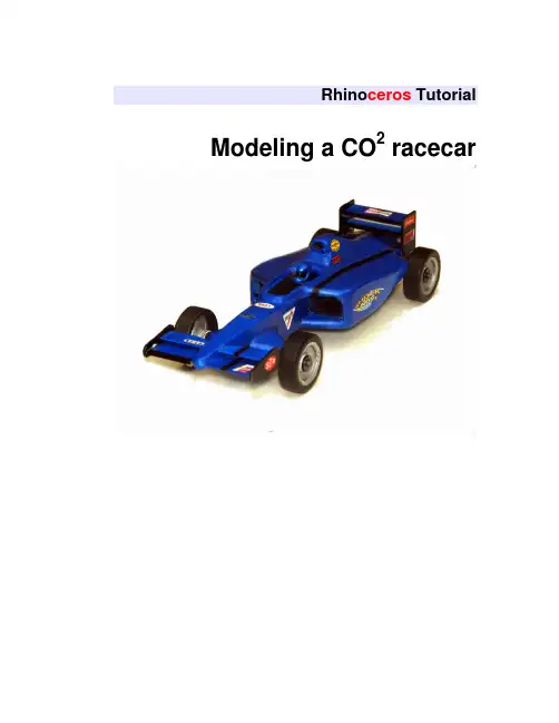
Rhino ceros Tutorial Modeling a CO2 racecarCopyright © 2005 Robert McNeel & Associates. All rights reserved.Rhino ceros is a registered trademark and Rhino is a trademark of Robert McNeel & Associates.Table of Contents1Introduction (4)Template files (4)2Model a CO2 Racecar for beginners (5)Starting a Model with a Template (5)Making the body of the racecar (7)Adding details to the racecar (13)3Model a CO2 racecar for intermediate users (17)Starting a Model with a Template (17)Placing the background bitmaps (19)Making the 2D geometry (20)Making the body of the racecar (28)Adding details to the racecar (32)4Preparing the model for machining (36)To make a stock box (37)Milling strategy (40)5Making a wheel and tire (41)To make the wheel (42)To make the tire (43)1 IntroductionThis tutorial describes how to model a racecar using Rhinoceros.There are several templates provided for your use. Each template includes a set ofpredefined layers to help you organize your model.Layers are a way of organizing objects so you can manipulate all the objects on aparticular layer or keep track of them. When objects are on a layer, you can turn them all off at once, change the color of the wire frame display, and select them all with oneselection.For more information about layers refer to the Rhino help file.Each of the templates has a layer with a set of wheels and axles and another layer witha model of a standard CO2 cartridge.Each template also has a layer named Max size that has rectangles that show themaximum size limits for the racecar. Your geometry must stay within these rectangles.You can turn the layers on or off at any time. Use the rectangles on these layers to check the size and positioning of your model.Template filesPlace the files that were included with the tutorial in a folder on your hard drive.Remember where they are located for later use.The files provided with this tutorial are:•Racecar.pdf•Beginner Racecar template inch.3dm•Beginner Racecar template mm.3dm•Beginner Racecar finished.3dm•Intermediate Racecar template inch.3dm•Intermediate Racecar template mm.3dm•Intermediate Racecar finished.3dm•Racecar Top.png•Racecar Front.png•Racecar Right.png2 Model a CO2 Racecar for beginnersIn this part of the tutorial you will learn how to: •Open a rhino model•Save a model•Turn layers on and off•Create surfaces•Trim and join the surfaces to form the body of the racecar.•Extrude the cockpit curves to cutoutthe cockpit from the body.•Extrude the strut curves to add to the body•Use Boolean operations•Use a cylinder to cut out the opening for the CO2cartridgeStarting a Model with a TemplateWhen starting a model in Rhino you can select a template. In this part of the tutorial you will select the Beginner Racecar Template Inch.3dm to begin the modeling process.Templates contain information that helps you get started such as units, layers, viewport layouts, and toolbars.LayersThe Racecar template for beginners includes seven predefined layers. Layers are a way of organizing objects so you can manipulate them separately or keep track of them in some way. It may help you to think of layers as transparent sheets on which you can place different parts of your model.The predefined layers have color properties that will let you distinguish various parts of the model more easily. In this template, all but one of the predefined layers includes construction geometry.Objects on a layer that is On are visible in the graphics area. Objects on a layer that is Off are not visible. Objects that are on an Unlocked layer are selectable. Objects on a layer that is Locked are not selectable. Geometry can only be created on the current layer.•The Max Size layer is on and locked. This layer contains rectangles that define the overall size of the racecar.•The Top Curves layer has geometry that defines the shape of the racecar.This layer correlates with the Top viewport.•The Front Curves layer contains the geometry to make surfaces for the struts and the cutout for the cockpit of the racecar. This layer correlates withthe Front viewport.•The Right Curves layer contains geometry with which to make the surface of the racecar’s topside. It also has curves for both the location of the CO2cartridge and the slot for the track cable.•The Wheel-Tire-Axle, and C02 Cartridge layers are off. You can turn them on during the modeling process to check the size and positioning of themodel.To display a shortcut popup for layers:`Click the Layer pane in the status bar, at the bottom of the Rhino window.The popup gives you access to common layer settings: on/off, locked/unlocked, color, and current status.Current layer indicated by a checkmark. Locked layer has the lock icon closed. Unlocked layer has thelock icon open.On layer has light bulb iconlighted.Off layer has the light bulb icongrayed out.To start the model1O n the File menu, click Open, selectBeginner Racecar Template Inch.3dm,and then click Open.2 On the File menu, click Save As, typeRacecar followed by your initials, and thenclick Save.Note: You should save regularly and often toavoid the loss of data.3 The next time you save, click Save, insteadof Save As.Making the body of the racecarIn this step, you will use the curves in the template to make surfaces. The curves are organized by layer. To make it easier to select the correct curves for each surface, lock the layers that are not needed for each step.As you make the surfaces, you will notice that the surfaces are larger than necessary.After making the surfaces, you will learn to use Boolean commands to trim and join the surfaces.To lock a layer1 Click the Layer pane on the Status bar.2 On the Layer Shortcut Popup, click the Lock icon for the Top Curves and FrontCurves layers.The lock icon is closed.To make the top surface1Select the five curves for the top of theracecar as illustrated (Right Curves layer).To select more than one curve hold down theShift key while picking.2 On the Surface menu, click Loft, changethe Style to Normal, and select Do notsimplify for the Cross-section curveoptions, then click OK.If the lofted surface is not satisfactory foryour design, you can change the shape andposition of the curves and make the loftagain.To make the side surfacesIn this part of the tutorial you will be making an extruded solid.The extrude command has several options:Direction, BothSides, Cap, Mode, and DeleteInput. We will be using the BothSides option in this tutorial.To change the BothSides option you can click on the word BothSides on the command line. Each time you click it will switch the option from BothSides=No to BothSides=Yes or back to BothSides=No.1Unlock the layer Top Curves and lock thelayer Right Curves.2Select the curve for the side surface as illustrated.3 On the Solid menu, click Extrude PlanarCurve, and then click Straight.4 At the Extrusion distance… prompt, setBothSides=No, then type 2 and pressENTER.If the BothSides option is set to Yes, click it to switch it to No.To check the normal direction of a surface 1Select the lofted surface for the top of theracecar.2 On the Analyze menu, click Direction.3 At the Press Enter when … prompt, pressENTER if the arrows are pointing down.If the arrows are pointed up, click Flip,then press ENTER.Note: The direction arrows should be pointing down or the next step will not give thecorrect results.To subtract the top surface from the side solid1 Select the solid you just completed.2 On the Solid menu, click Difference.3 At the Select second set of surfaces orpolysurfaces prompt, setDeleteInput=Yes, then select the toplofted surface, and then press ENTER.If the DeleteInput option is set to No, click itto switch it to Yes.This will trim and join the two pieces together. To make the cutout surface for the cockpit1Unlock the layer Front Curves and lock the layer Top Curves.2Select the U-shaped curve at the top, center of the model.3 On the Surface menu, click ExtrudeCurve, and then click Straight.4 At the Extrusion distance… prompt, setBothSides=Yes, then type 1.25 and pressENTER.If the BothSides option is set to No, click itto switch it to Yes.To check the normal direction of a surface1Select the extruded surface you just made.2 On the Analyze menu, click Direction.3 At the Press Enter when … prompt, pressENTER if the arrows are pointing outwards.If the arrows are pointed inwards, click Flip, then press ENTER.The direction arrows should be pointingoutwards.To make the cutout the cockpit1 Select the body of the racecar.2 On the Solid menu, click Difference.3 At the Select second set of surfaces orpolysurfaces prompt, setDeleteInput=Yes, then select theextruded surface that will be used to cut outthe top of the cockpit, and then pressENTER.If the Delet e Input option is set to No, click it to switch it to Yes.Adding details to the racecarIn the last part of the tutorial, we will add a strut for the front axle and remove some of the model to make a space for a CO2 cartridge and to make a slot in the bottom.To make the slot for the bottomIt might be easier to see the curves if you changethe viewport to a wireframe display.1Right click on the Perspective viewporttitle bar, then click Wireframe Display onthe dropdown menu.2UnLock the layer Right Curves and lockthe Front Curves layer.3Select the small rectangle at the bottom ofthe back of the template.4 On the Solid menu, click Extrude PlanarCurve, and then click Straight.5 At the Extrusion distance… prompt, setBothSides=No, then type 9 and pressENTER.6Right click on the Perspective viewporttitle bar, then click Ghosted Display onthe dropdown menu.To finish the slot for the bottom1Select the body of the racecar.2 On the Solid menu, click Difference.3At the prompt Select second set ofsurfaces or polysurfaces prompt, setDeleteInput=Yes, then select theextruded box you just completed, and thenpress ENTER.To make the hole for the CO2 cartridge1Drag the right mouse button in thePerspective viewport to rotate the view,so you can see the back of the racecarbody.2Select the circle at the back of the body.3 On the Solid menu, click Extrude PlanarCurve, and then click Straight.4 At the Extrusion distance… prompt, setBothSides=Yes, then type 3 and pressENTER.Notice that the cylinder penetrates 3 inches into the body and extends beyond 3 inches.Since we are going to remove the cylinderfrom the body with a Boolean differencecommand, having a clear intersectionbetween the parts is always better thantrying to make it flush.To make the hole for the CO2 cartridge1 S elect the body of the racecar.2 On the Solid menu, click Difference.3 At the Select second set of surfaces orpolysurfaces prompt, setDeleteInput=Yes, then select thecylinder, and then press ENTER.To make the front axle support1UnLock the layer Front Curves and lockthe Right Curves layer.2S elect the curve for the strut as illustrated.3 On the Solid menu, click Extrude PlanarCurve, and then click Straight.4 At the Extrusion distance… prompt, setBothsides=Yes, then type 1.125 andpress ENTER.To add the support to the body1Lock the layer Front Curves.2 On the Solid menu, click Union.3 At the Select surfaces or polysurfacesto union prompt, select the body and thenthe strut, and then press ENTER.To see the finished racecar1 Turn on the layers Wheel-Tire-Axle andCO2Cartridge.2 Turn off the layers Top Curves, FrontCurves, Right Curves and Max Size.3 Model a CO2 racecar for intermediate usersIn this tutorial, you will learn how to make a CO2 racecar starting from sketches. Before attempting this tutorial, make sure you already have experience using Rhino and that you understand everything discussed in Chapter 2 of this tutorial.You will learn how to:•Place Background Bitmaps•Use object snaps•Use layers•Make lines, curves and arcs•Mirror geometry•Extrude 2-D curves to make surfaces andsolids•Use the Loft command to make a surface•Trim and join surfaces•Use the BooleanDifference command to hollow out the cockpit and make a hole forthe CO2 cartridge•Use the BooleanUnion command to add struts to the body of the racecar Starting a Model with a TemplateWhen starting a model in Rhino you can select a template. In this part of the tutorial you will select the Intermediate Racecar Template Inch.3dm to begin the modelingprocess. Templates contain information that helps you get started such as units, layers, viewport layouts, and toolbars.This template includes eight predefined layers.Three of the predefined layers also include construction geometry.•The Max Size layer is on and locked. This layer contains rectangles that define theoverall size of the racecar.•The Wheel-Tire-Axle, and C02 Cartridge layers are off. You can turn them onduring the modeling process to check the size and positioning of the model.Modeling aids can help you draw the 2-D geometry with more precision. In this tutorial you will use the object snap (Osnap) and ortho modeling aids. You can find the controls for modeling aids on the status bar at the bottom of the Rhino window.Object snaps make it easy to snap precisely to various parts of the geometry. In this tutorial, we will use the End, Near, Point and Cen object snaps to attach geometry to the provided construction geometry.Note Object snaps are crucial to accurate modeling. Never try to place things visually on the screen; it is too difficult, and it is impossible to ensure accuracy.To start the model1O n the File menu, click Open, selectIntermediate Racecar TemplateInch.3dm, and then click Open.2 On the File menu, click Save AsTemplate, type Racecar template, thenclick Save.This adds the provided template file to theRhino template folder.3 On the File menu, click New, selectRacecar template.3dm, and then clickOpen.This starts a new modeling session with a filecalled unnamed.3dm.4 On the File menu, click Save, type Racecar followed by your initials, and thenclick Save.To turn on modeling aids` On the status bar, click the Osnap pane.These controls are toggles. Click a check box once to turn the aid on; click again to turn it off. When modeling aids are on, their check boxes are checked.Clicking the Osnap pane toggles the display of the Osnap toolbar.The Osnap pane text is bold only when one or more of the object snap check boxes are selected.You will be using the Osnap toolbar in this tutorial, so make sure it is displayed.Placing the background bitmapsWe will start by placing the background image for the top viewport.To place a background bitmap in the top viewport1Click in the Top viewport to make it active, Array and turn on the End osnap.2 On the View menu, click BackgroundBitmap, then click Place, selectRacecar Top.png and then click Open.3 At the First corner prompt, snap to theEndpoint at the lower left corner of thelocked rectangle in the Top viewport.4 At the Second corner or length prompt,snap to the Endpoint at the upper rightcorner of the locked rectangle in the Topviewport.If you can not see the placed bitmap in theTop viewport background, on the Viewmenu, click Background Bitmap, then clickShow.Once you have placed the image, you can adjust it if necessary.To adjust background images, use View>Background Bitmap>Move to move the image. Use View>Background Bitmap>Scale to scale the image. UseView>Background Bitmap>Align to move and scale the image at the same time.To place a background bitmap in the front viewport1C lick in the Front viewport to make it Array active. On the View menu, clickBackground Bitmap, then click Place,select Racecar Front.png and then clickOpen.2 At the First corner prompt, snap to theEndpoint at the lower left corner of thelocked rectangle in the Front viewport.3 At the Second corner or length prompt,snap to the Endpoint at the upper rightcorner of the locked rectangle in the Frontviewport.To place a background bitmap in the right viewport1C lick in the Right viewport to make it active. On the View menu, clickBackground Bitmap, then click Place,select Racecar Right.png and then clickOpen.2 At the First corner prompt, snap to theEndpoint at the lower left corner of therectangle in the Right viewport.3 At the Second corner or length prompt,snap to the Endpoint at the upper rightcorner of the rectangle in the Rightviewport.After placing the bitmaps and adjusting them, you can begin making the geometry bytracing over the top of the images.Making the 2D geometryNext, you will create the 2D geometry that to make the side, top, and bottom surfaces.To make the curve for the side surface1Turn on the Mid osnap, and click Projecton the Osnap toolbar.Project allows you to snap to geometry whilekeeping the snap point on the constructionplane.2 On the Curve menu, click Free-Form, andthen click Control Points.3 At the Start of curve prompt, start fromthe lower left side of the rectangle in theTop viewport.4 At the Next point prompt, continue placingpoints along the rear wheel well, and thencontinue placing points to make a curvethat follows the outline of the bitmap.End the curve so that it snaps to the midpointof the vertical edge at the right side of therectangle. Make sure the curve stays on orinside the frame of the rectangle.The last two points (1 & 2) should be Orthoto each other as in the illustration on theright. This will insure tangency when youmirror the curve.To mirror the curve for the side surface1Select the curve you just completed.2 On the Transform menu, click Mirror.3 At the Start of mirror plane prompt, snapto the End of the curve you just completed.4 At the End of mirror plane prompt snap tothe End of the construction line at themiddle left of the rectangle.To hide the background bitmapWhen modeling you might need to turn background bitmaps on and off to make it easier to work with the geometry.1Right-click on the Top viewport title.2 On the Viewport title menu, click Background bitmap, then click Hide.To show the background bitmap, you can repeat the process and click Show.To make the curve for the back surface1T urn on the Int osnap.2 On the Curve menu, click Line, then clickSingle line.3 Snap to the intersection points as illustratedto draw a line.To trim and join the three curves1 Select the line you just completed.2 From the Edit menu, click Trim.3 At the Select object to trim…, select theleft end of each of the side curves, thenpress ENTER to end the trim command.4 Select the two side curves and the backline.5 From the Edit menu, click Join.To make curves for the bottom surface, the side profile, and the cutout for the cockpit1C hange to the Front Curves layer.2Turn off the Top Curves layer.3 On the Curve menu, click Free-Form, andthen click Control Points.4Make curves for the cockpit profile, the sideprofile, and the bottom profile of theracecar.Start and end the curves so that they extendbeyond the construction lines.To make a copy of the side profile curveThe side profile curve is a construction line for the right profile curves. We will make a copy of the curve to help in constructing the right side profiles.1Select the side profile curve (middle curve).2 From the Transform menu, click Copy.3 At the Point to copy from… prompt,type 0 and press ENTER.4 At the Point to copy to prompt,type 0,-1.5 and press ENTER.To lock the side profile curvesSince we are using these two curves to help construct the right side profiles, they need to be visible, but we don’t want to accidentally move them. Locked geometry is not selectable for editing, but you can still use object snaps on it.1Select the two curves.2 From the Edit menu, click Visibility, then click Lock.To make the cross-section curves for the top surfaceIn this step, you will make one curve for the back of the car. Then you will copy this curve and adjust it to make a set of cross-section curves for the top surface of the racecar. This technique insures that each curve has the same degree and the same number of points. Using a set of curves with the same parameterization generally makes a much cleaner surface.After copying the curves, manipulate each curve by moving the control points to get the final shape for your racecar.To maintain symmetry, make one-half of the curve and then mirror it.1C hange to the Right Curves layer.2 On the Curve menu, click Free-form, andthen click Control Points.3 At the Start of curve prompt, snap bottomend of the locked curve on the left in theRight viewport.4 At the Next point prompt, place 3 or 4points to the right.5 At the Next point prompt,continue placing points to match the construction arcon the Max Size layer.The arc represents the minimum clearance for the CO2 cartridge at the back of the racecar.6End the curve so that it snaps to the midpoint of the arc.To adjust the control points for the base curveTo make sure the control points at the bottom and top of the curve are ortho to each other, we will use the Set Point command to position the points on the same z elevation.1S elect the curve you just created.2 From the Edit menu, click Control Points,then click Control Points On.You can also use the F10 key to turn thecontrol points on.3Select the control points along the bottomof the curve.4 From the Transform menu, click SetPoints.5 On the Set Points dialog, uncheck X andY, check Z, then click OK.The Align to World radio button should beactive.6At the Location for points prompt, snap thelower end of the locked construction line.7 Repeat this process for the two points at thetop of the arc.To mirror the profile curve1Select the curve you just completed.2 On the Transform menu, click Mirror.Since the orientation of the template is on theorigin of the model, we will use the origin asthe start of the mirror plane.3 At the Start of mirror plane prompt, type0 and press ENTER.4 At the End of mirror plane prompt, turnOrtho on and move you mouse pointer upor down and click.To join the profile curve1Select the curves you just completed.2 On the Edit menu, click Join.The two curves are joined into one.To place the first curveIn this step, you will move the curve you just completed to the end of the copied side profile curve (locked curve).1Turn on the End and Mid osnap, and uncheck all the others.2 Turn off Project.3 Select curve you just joined.4 On the Transform menu, click Move.5 At the Point to move from prompt, snapto the left End of the cross-section curve.6 At the Point to move to prompt, snap tothe left Endof the copied side profile curve.To copy the curves for the top of the bodyIn this step you will copy the curve along the construction curve. The first set of copies will be for the main body and cockpit.1 T urn on the End, Near and Mid osnaps,and uncheck all the others.2Copy of the curve you just completed.3 At the Point to copy from prompt, snap tothe left Endpoint of the curve.4 At the Point to copy to prompt, snap topoints along the copy of the side profilecurve using the Near osnap.The first copy of this curve should be approximately 2 inches from the left end of the rectangle.The positioning of these curves will affect the shape of the top surface. If you are not happy with the shape after you make the surface, you can adjust the curves and remake the surface.5 Press ENTERto end the command.To copy the curves for the noseIn this step you will copy one of the copies you made in the previous step for the nose of the racecar.1 Select the last copy of the curve from theprevious step.2Copy of the curve3 At the Point to copy from prompt, snap tothe Endpoint of the curve.4 At the Point to copy to prompt, snap topoints along the original side profile curveusing the Near osnap.5 Continue to copy the curve along theoriginal side profile curve.When finished you should have six duplicatecurves arranged like the illustrations below.It is generally better to have curves withsimilar structure when making surfaces. Usingthis technique, the curves will have the samenumber of control points and parameterspacing.Making the body of the racecarIn this step, you will use the curves you just completed to make surfaces. The surfaces will be larger than necessary. After making the surfaces, trim them with the adjacent surfaces to finish the model.To make the top surface1 Select Surfaces as the current layer.2Turn the layers Top Curves, FrontCurves, and Max Size off.3Select the six curves you just completed.4 On the Surface menu, click Loft, changethe Style to Loose, and select Do notsimplify for the Cross-section curveoptions, then click OK.If the lofted surface is not satisfactory foryour design, you can change the shape andposition of the cross-section curves and makethe loft again.To adjust the shape of the cross-section curves for the top of the racecarIn this step you will adjust control points of the copied curves to develop the final shape for the top surface of the racecar. You will also learn how to use the nudge keys to move the points.Moving control pointsThere are several methods to move the control points:•You can simply select and drag the control pointsWith the select and drag method, you do not get much precision.•You can use the Move commandThe Move command allows the precision, but it can be a little tedious to use.•You can Nudge the control pointsNudge gives you both precision and it is easy to use, especially when you only need to move the points a small amount.Nudge keys and directionAlt+Arrow keys are used for the nudge keys. The Alt+Ctrl+Arrow and theAlt+Shift+Arrow are variations.The nudge keys move the selected objects in relation to World or Construction Plane axes of the active viewport, Construction Plane is the default setting. Each keycombination determines the amount of movement:Alt + Arrow moves .2 <units>, the Alt + Ctrl + Arrow moves .05 <units>,Alt + Shift + Arrow moves 2 <units> in the direction of the arrow1S elect the curve to adjust.2 From the Edit menu, click Control Points,then click Control Points On.You can also use the F10 key to turn the control points on.3Select the control points to adjust.4 Hold the Alt key and press one of theArrow keys to move objects in the x or ydirection in the active viewport.5Repeat this step for the control points onthe other side of the curve to maintainsymmetry.。

汽车犀牛建模教程-CAL-FENGHAI.-(YICAI)-Company One1汽车造型设计【预览效果】图5.5.1 预览效果【知识点】【Scale NU】不等比例缩放【Properties】编辑物体属性【NetworkSrf】空间曲线形成曲面【Analyze direction】分析曲线或曲面法线方向【难点分析】(1) 两曲面衔接的平滑处理,可调整生成曲面的曲线使其与已有曲面相切来实现。
(2) 生成曲面的网格数量与曲线法线方向的控制。
曲线法线方向不同,生成曲面的效果就不同。
通常曲线的数量越少,生成的曲面就越光顺。
不规则曲面的形成主要是通过构造曲线来生成。
(3) 曲线可以对曲面修剪,曲面可以对实体修剪,但曲线不可以修剪实体。
【制作步骤】5.5.1车身1) 新建图层单击,在对话框中新建如图5.5.2所示的6个图层,选择车身表面为当前图层。
图5.5.2 设置图层2) 绘制车身骨架曲面(1) 绘制平面曲线。
单击,结合三视图绘制三条平面曲线,如图5.5.3所示。
图5.5.3 绘制平面曲线(2) 绘制汽车框架曲线。
在【Top】视图沿垂直方向和水平方向对三条平面曲线分别进行复制。
如图5.5.4所示。
图5.5.4 绘制框架曲线(3) 绘制平面曲线。
激活【Top】视图,单击,绘制平面曲线,如图5.5.5所示。
图5.5.5 绘制平面曲线(3) 一轨成型生成曲面。
单击,以图5.5.5绘制曲线为轨迹一轨成型生成曲面,对话框设置为rebuild with 10 control points,生成半个粗略车身侧面。
如图5.5.6所示。
(4) 提取曲面结构线。
激活【Top】视图,单击,选择车身侧面曲面,在车身侧面曲面上提取多条结构线。
如图5.5.7 所示。
图一轨成型生成曲面图提取曲面结构线(5) 删除车身侧面曲面及图与图所绘曲线。
如图所示。
图5.5.8 提取后的曲线(6) 重建曲线控制点。
单击,框选所有曲线,重建曲线控制点。
RHINO犀牛基础教程
在这篇文章中,我们将为您介绍Rhino(犀牛)的基础知识。
Rhino 是一款三维建模工具,被广泛应用于工业设计、建筑设计以及珠宝设计等领域。
它以其强大的建模和分析能力闻名,可以帮助设计师将想法转化为现实的模型。
Rhino(犀牛)的界面非常直观,容易上手。
一旦您打开软件,首先看到的是3D视图窗口、工具栏和命令行。
在3D视图窗口中,您可以使用鼠标旋转、缩放和移动模型,以便从不同角度观察模型。
要开始创建对象,您可以使用Rhino的基本几何图形工具。
点击菜单栏中的“绘图”选项,您将看到诸如点、线、弧、曲线等工具。
选择相应的工具后,您可以在3D视图窗口中点击鼠标来绘制对象。
例如,如果您想绘制一条线,点击工具栏中的“直线”按钮,然后在3D视图窗口中点击两个点,就会生成一条直线。
除了基本几何图形工具之外,Rhino还包含了高级建模工具。
例如,您可以使用曲面工具创建复杂的曲线,然后通过拉伸、修剪和旋转来生成实体。
此外,Rhino还提供了布尔运算工具,可以根据交集、差集和并集等操作创建新对象。
综上所述,Rhino是一款功能强大的三维建模工具,可用于各种设计领域。
无论您是初学者还是专业设计师,都可以通过掌握Rhino的基础知识来创建精美的模型。
希望这篇文章对您有所帮助,祝您在使用Rhino时取得成功!。
Rhino3D汽车建模教学第一章:简介Rhino3D是一款强大的三维建模软件,广泛应用于汽车设计领域。
本章将介绍Rhino3D的基本功能和特点,以及其在汽车建模中的优势。
Rhino3D具有友好的用户界面和强大的建模工具,可以快速创建复杂的汽车模型。
与其他建模软件相比,Rhino3D具有更灵活的建模方式和更高的建模精度。
可以实现从二维草图到三维模型的快速转换。
第二章:汽车建模基础在进行汽车建模前,我们需要了解汽车的基本结构和外形特点。
本章将介绍汽车的构造和重要组成部分,包括车身、底盘、发动机等。
了解汽车的基本结构对于进行准确的建模非常重要。
掌握汽车各个部件的形状和比例,是建立真实、逼真的汽车模型的基础。
第三章:Rhino3D建模工具Rhino3D提供了丰富多样的建模工具,可以满足各种汽车建模需求。
本章将介绍Rhino3D中常用的建模工具,包括曲线工具、曲面工具和实体工具等。
曲线工具可以用于绘制车身的轮廓线和细节线,曲面工具可以用于创建车身的曲面面板和弯曲部分,实体工具可以用于创建汽车的零件和结构。
第四章:汽车建模技巧汽车建模需要细致入微的处理,以保证模型的真实性和精度。
本章将介绍一些常用的汽车建模技巧,包括对称建模、细节建模和流线建模等。
对称建模可以减少建模时间和劳动力,保证车身的两侧完全对称。
细节建模可以增加模型的细节和真实感,提升视觉效果。
流线建模可以优化车身的气动性能,提高汽车的运行效率。
第五章:材质和纹理为汽车模型添加逼真的材质和纹理是提高模型质量的重要一环。
本章将介绍Rhino3D中的材质和纹理编辑器,以及如何将其应用到汽车模型上。
Rhino3D提供了丰富的材质和纹理库,可以满足各种材质和纹理的需求。
通过调整材质的颜色、光泽和反射等属性,可以使汽车模型更加逼真。
第六章:渲染和动画在完成汽车建模后,我们可以使用Rhino3D提供的渲染和动画功能,为模型增加更多的效果和吸引力。
本章将介绍渲染和动画的基本操作和常用技巧。
汽车造型设计【预览效果】图预览效果【知识点】【】不等比例缩放【】编辑物体属性【】空间曲线形成曲面【】分析曲线或曲面法线方向【难点分析】()两曲面衔接的平滑处理,可调整生成曲面的曲线使其与已有曲面相切来实现。
()生成曲面的网格数量与曲线法线方向的控制。
曲线法线方向不同,生成曲面的效果就不同。
通常曲线的数量越少,生成的曲面就越光顺。
不规则曲面的形成主要是通过构造曲线来生成。
()曲线可以对曲面修剪,曲面可以对实体修剪,但曲线不可以修剪实体。
【制作步骤】车身)新建图层单击,在对话框中新建如图所示的个图层,选择车身表面为当前图层。
图设置图层)绘制车身骨架曲面()绘制平面曲线。
单击,结合三视图绘制三条平面曲线,如图所示。
图绘制平面曲线()绘制汽车框架曲线。
在【】视图沿垂直方向和水平方向对三条平面曲线分别进行复制。
如图所示。
()绘制平面曲线。
激活【】视图,单击,绘制平面曲线,如图所示。
图绘制平面曲线()一轨成型生成曲面。
单击,以图绘制曲线为轨迹一轨成型生成曲面,对话框设置为,生成半个粗略车身侧面。
如图所示。
() 提取曲面结构线。
激活【】视图,单击,选择车身侧面曲面,在车身侧面曲面上提取多条结构线。
如图所示。
() 删除车身侧面曲面及图与图所绘曲线。
如图所示。
() 重建曲线控制点。
单击,框选所有曲线,重建曲线控制点。
对话框设置如图所示。
()调整曲线控制点。
单击,打开曲线控制点,结合三视图调整曲线控制点。
如图所示。
图调整曲线控制点()放样曲线成曲面。
单击,框选所有曲线,对话框设置为,生成车身侧面。
如图所示。
(此处生成的曲面若不理想,可重新返回上一步重新调整曲线控制点,反复操作直到调出满意曲面)图放样生成曲面()选择所有曲线,按【】删除。
(此步是为方便以后操作,读者也可选择将其隐藏) )绘制发动机罩()绘制平面曲线。
激活【】视图,单击,在车身前端绘制如图所示平面曲线。
()修剪车身侧面。
单击,在【】视图上对车身侧曲面修剪,如图所示。
犀牛模型操作方法犀牛(Rhino)是一款由美国Robert McNeel & Associates开发的三维造型软件,广泛应用于工业设计、建筑设计、产品设计、珠宝设计等领域。
在犀牛软件中,使用犀牛模型来进行三维建模和编辑操作。
下面将详细介绍犀牛模型的操作方法。
1. 创建和编辑基本几何体:在犀牛软件中,可以通过几何体命令创建各种基本几何体,如立方体、球体、锥体、圆柱体等,还可以通过编辑命令对其进行修改和变形。
例如,使用“Box”命令创建一个立方体,可以通过输入尺寸参数或通过拖动鼠标来确定立方体的大小和位置。
使用“Move”命令可以移动和平移几何体,使用“Rotate”命令可以旋转几何体,使用“Scale”命令可以缩放几何体。
2. 组合和分割几何体:在犀牛软件中,可以将多个几何体组合成一个整体,也可以将一个几何体分割成多个部分。
使用“Union”命令可以将多个相交的几何体合并成一个整体,使用“Split”命令可以将一个几何体分割成多个部分,使用“Boolean”命令可以进行几何体的布尔运算,如求并集、交集、差集等。
3. 创建曲线和曲面:在犀牛软件中,可以通过曲线和曲面命令创建各种形状的曲线和曲面。
例如,使用“Polyline”命令可以创建多段线,使用“Circle”命令可以创建圆,使用“Curve”命令可以创建自由曲线,使用“Surface”命令可以创建曲面。
还可以使用“Edit”命令对曲线和曲面进行修改和调整。
4. 进行布尔运算:在犀牛软件中,可以对几何体进行布尔运算,如求并集、交集、差集等。
使用“BooleanUnion”命令可以将多个相交的几何体合并成一个整体,使用“BooleanIntersection”命令可以求多个几何体的交集部分,使用“BooleanDifference”命令可以求两个几何体的差集部分。
5. 创建和编辑自由曲面:犀牛软件支持创建和编辑自由曲面,可以通过控制点来调整曲面的形状。
犀牛模型基本操作方法
犀牛模型的基本操作方法如下:
1. 创建新模型:打开犀牛软件后,点击“文件”菜单,选择“新建”来创建一个新的模型。
2. 绘制基本形状:选择合适的绘图工具,例如直线工具、曲线工具、多边形工具等,开始绘制模型的基本形状。
3. 修改形状:选择编辑工具,用于对已绘制的形状进行修改和调整,例如移动、旋转、缩放等。
4. 添加细节:可以使用细分表面、偏移、曲面等工具来添加细节和平滑模型。
5. 修复错误:在模型创建过程中可能出现错误或不完整的部分,可以使用修复工具来进行修复和补充。
6. 创建剖面:使用剖面工具可以将模型切割成各个部分,方便观察和修改。
7. 生成输出:完成模型的设计后,可以选择输出成不同的文件格式,例如STL、OBJ等,用于进一步使用和处理。
8. 渲染和展示:使用渲染工具可以对模型进行渲染和展示,以便更好地观察模型的效果和细节。
这些是犀牛模型的基本操作方法,通过不断练习和熟悉软件,可以掌握更多高级的模型操作技巧。
用Rhino做Shelby Cobra 轿车教程
本教程将演示如何制作Shelby Cobra轿车的车身。
其它
一些小部件如轮胎、油箱等本教程均作省略。
汽车造模时,最难的是车身,因为它一般都是非常光滑的曲面。
用Rhino来做此项工作,是个不错的主意
仔细观察上面的一幅图片,你不难发现它象是汽车车身的廓线。
它们能帮助完成最后的造模工作。
与多边形造模不同,NURBS曲面造模就是靠这样的样条曲线来勾描图形的。
仔细观察上面的一幅图片,你不难发现它象是汽车车身的廓线。
它们能帮助完成最后的造模工作。
与多边形造模不同,NURBS曲面造模就是靠这样的样条曲线来勾描图形的。
根据车身形状用一条非封闭的曲线画出它的横截面图
拷贝刚才画的曲线生成第二条横截面曲线,并将它向下移动一些,修改若干控制点,形成的结果如上图。
依此类推,根据车身形状,画出其不同区段的横截面曲线,以备下一步放样用。
用画出的这些曲线进行放操作,结果如上图所示。
如上图所示用拉伸(Extrude)曲线的方法,在车头部分挖出一个口子,形成汽车散热器及保
险杠的形状。
用同新的拉伸样条曲线的方法在车身上挖出蔽蓬车座的位置。
如上图,画出车轮箱处的弧形边线,再做一次拷贝,并将拷贝的曲线缩小,稍稍移离车体,然后放样这两条曲线,形成车体车轮箱处略微突出的边缘。
汽车造型设计【预览效果】图5.5.1预览效果【知识点】【Scale NU】不等比例缩放【Properties】编辑物体属性【NetworkSrf】空间曲线形成曲面【Analyze direction】分析曲线或曲面法线方向【难点分析】(1)两曲面衔接的平滑处理,可调整生成曲面的曲线使其与已有曲面相切来实现。
(2) 生成曲面的网格数量与曲线法线方向的控制。
曲线法线方向不同,生成曲面的效果就不同。
通常曲线的数量越少,生成的曲面就越光顺。
不规则曲面的形成主要是通过构造曲线来生成。
(3)曲线可以对曲面修剪,曲面可以对实体修剪,但曲线不可以修剪实体。
【制作步骤】5.5.1车身1)新建图层单击,在对话框中新建如图5.5.2所示的6个图层,选择车身表面为当前图层。
图5.5.2设置图层2)绘制车身骨架曲面(1)绘制平面曲线。
单击,结合三视图绘制三条平面曲线,如图5.5.3所示。
图5.5.3绘制平面曲线(2)绘制汽车框架曲线。
在【Top】视图沿垂直方向和水平方向对三条平面曲线分别进行复制。
如图5.5.4所示。
图5.5.4绘制框架曲线(3)绘制平面曲线。
激活【Top】视图,单击,绘制平面曲线,如图5.5.5所示。
图5.5.5绘制平面曲线(3)一轨成型生成曲面。
单击,以图5.5.5绘制曲线为轨迹一轨成型生成曲面,对话框设置为rebuild with 10 control points,生成半个粗略车身侧面。
如图5.5.6所示。
(4) 提取曲面结构线。
激活【Top】视图,单击,选择车身侧面曲面,在车身侧面曲面上提取多条结构线。
如图5.5.7 所示。
图一轨成型生成曲面图提取曲面结构线(5) 删除车身侧面曲面及图与图所绘曲线。
如。
图5.5.8 提取后的曲线(6) 重建曲线控制点。
单击,框选所有曲线,重建曲线控制点。
对话框设置如图5.5.9所示。
图5.5.9 对话框设置(7)调整曲线控制点。
单击,打开曲线控制点,结合三视图调整曲线控制点所示。
图5.5.10 调整曲线控制点(8)放样曲线成曲面。
单击,框选所有曲线,对话框设置为rebuild with 10 control points,生成车身侧面。
如图5.5.11所示。
(此处生成的曲面若不理想,可重新返回上一步重新调整曲线控制点,反复操作直到调出满意曲面)图5.5.11 放样生成曲面(9)选择所有曲线,按【Delete】删除。
(此步是为方便以后操作,读者也可选择将其隐藏)3)绘制发动机罩(1)绘制平面曲线。
激活【Top】视图,单击,在车身前端绘制如图5.5.12所示平面曲线。
(2)修剪车身侧面。
单击,在【Top】视图上对车身侧曲面修剪,如图5.5.12所示。
图5.5.12修剪车身侧面(3)绘制空间曲线。
激活【Top】视图,单击,绘制平面曲线。
单击打开曲线控制点,在【Right】视图上选择相应的控制点做适当调整。
如图5.5.13所示。
图5.5.13绘制空间曲线(4)镜像车身侧面曲面和曲线。
单击,选中车身侧面曲面和图5.5.13所绘曲线在【Top】视图上进行镜像处理。
如图所示。
(5)空间曲线生成发动机罩曲面。
单击,选择如图5.5.15所示的边缘与曲线生成曲面。
如所示。
图5.5.14 镜像车身侧面图空间曲线生成曲面图发动机罩曲面(6) 增加曲面控制点。
单击,选择车身侧面曲面,分别在U、V方向增加适当的控制点。
如图,所示。
图增加曲面控制点图增加曲面控制点后效果(7) 调整曲面控制点。
选择图所示控制点在【Top】和【Front】视图上作适当的调整。
如,所示。
图调整曲面控制点图调整曲面控制点调整控制点后效果(8)修剪车身曲面。
激活【Top】视图,单击,绘制平面曲线,如图所示。
单击,对车身侧曲面和发动机罩进行修剪,如所示。
图绘制平面曲线图修剪后的曲面4)绘制汽车前围(1)绘制平面曲线。
隐藏发动机罩及半个车身侧面曲面。
激活【Right】视图,单击,绘制平面曲线,如图所示。
(2)分割车身前部。
单击,将曲线投影到汽车的前脸上;单击,用投影曲线对车身前脸进行分割。
如图所示。
图绘制平面曲线分割车身前部(4)缩小曲面。
单击,在【Right】视图上对曲面分别进行横向和纵向的缩小,如图所示。
图移动曲面两维缩小曲面(5)混合曲面。
单击,选择相应的边混合两曲面,对话框设置为默认设置,如图所示。
(6)绘制平面曲线。
激活【Right】视图,单击,绘制平面曲线。
如图所示。
(7)分割曲面。
单击,用曲线对曲面进行分割。
如图所示。
图混合两曲面绘制平面曲线图分割生成的曲面5) 对车身侧面处理(1)绘制平面曲线。
激活【Front】视图,单击,绘制两根平面曲线;单击,用绘制的曲线修剪车身侧面。
如图所示。
图修剪车身侧面(2)绘制平面曲线。
激活【Front】视图,单击,绘制如图所示的两小段平面曲线。
(3)一轨成形生成曲面。
单击,一轨成形生成车轮上部曲面,如图所示。
后轮处绘制方法同前轮相同。
如所示。
图绘制平面曲线一轨成形生成曲面图生成曲面车轮上部6) 发动机罩实体生成(1)拉伸曲面生成实体。
单击,选择发动机罩曲面拉伸生成如图所示实体;删除发动机机罩曲面。
(2)发动机罩倒圆角处理。
单击,对生成的实体进行适当的倒圆角。
如图所示。
图拉伸生成实体倒圆角处理(3)对其它部分同样作拉伸和倒圆角处理,这里不详细介绍。
如图所示。
图发动机罩效果图7)绘制前灯罩(1)单击,提取车身侧面曲面。
(2)绘制平面曲线。
激活【Top】视图,单击,绘制图所示平面曲线。
(3)投影曲线到曲面。
单击,在【Top】视图中投影曲线到侧面曲面。
如图所示。
图绘制平面曲线投影曲线到曲面(4)分割曲面。
单击,用曲线对曲面进行分割。
如图所示。
(5)车灯罩实体生成。
用生成发动机罩的方法生成车灯罩并倒圆角。
如图所示。
图分割曲面前车灯罩生成(6)后车灯罩生成同前车灯罩生成类似,如图所示,车尾生成同车前脸生成,效果如所示。
图后车灯罩车尾部效果8)绘制行李箱盖(1) 绘制空间曲线。
激活【Top】视图,单击,绘制如图所示四条平面曲线。
单击打开曲线控制点,选择相应的控制点在三视图上做适当调整成空间曲线。
图绘制空间曲线(2)分割曲线。
单击,提取如图所示曲线。
单击,在曲线上适当位置上放置点。
单击,用点将曲线打断。
(此步为下面完成两轨成形做准备)(3)两轨成形生成曲面。
单击,选择如图所示○1、○2曲线为两轨生成行李箱盖的曲面。
如所示。
图分割曲线两轨成形的曲线(4) 行李箱实体生成同前车灯罩,如图所示。
图两轨成形生成曲面行李箱盖的形成9)绘制汽车后翼(1)修剪车身侧面。
单击按钮,在【Top】视图上绘制平面曲线,如图所示。
单击,提取车身侧面曲面。
单击,用曲线对车身侧面曲面进行修剪。
如所示。
(2)绘制空间曲线。
单击,绘制两根平面曲线。
单击,调整曲线控制点生成空间曲线,如图所示。
图绘制空间曲线(3)两轨成形。
单击,选择如图所示○A、○B曲线为两轨生成汽车后翼的曲面。
如所示。
(4) 单击,提取汽车后翼曲线。
如图所示。
图两轨成形生成曲面提取曲线(5) 生成汽车尾翼。
选择曲线拉伸生成曲面并做适当的修剪。
如图所示。
图汽车后翼效果图5.5.2顶盖及风窗1)选择图层选择顶盖及风窗图层,如图所示。
图选择图层2)绘制汽车前窗(1)绘制空间曲线。
单击,在【Top】上绘制如图所示三条平面曲线。
单击打开曲线控制点,选择平面曲线上相应的控制点在三视图上做适当调整,生成所需的空间曲线。
如所示。
图绘制空间曲线(2)两轨成形。
单击,选择相应曲线两轨成形生成风窗曲面。
如图所示。
(3)修剪风窗曲面。
激活【Top】视图,单击,绘制平面曲线,单击用曲线对风窗曲面进行修剪,如图所示。
图两轨成形修剪曲面(4)复制风窗。
单击,在同一位置复制风窗。
并将复制的部分隐藏。
(此复制的风窗即下面的黑色玻璃)(5)拉伸成实体。
单击,选择风窗拉伸生成实体,并对其倒圆角。
如图所示。
(6)绘制平面线框。
激活【Right】视图,单击,绘制平面曲线,如所示;拉伸生成实体并对风窗进行布尔减运算。
显示玻璃部分并拖动到恰当位置,如所示。
图生成实体绘制平面线框3)绘制顶盖(1)单击,提取风窗上一曲线,如所示。
(2)点击,在曲线上的恰当位置放置一点。
单击,用点将曲线打断。
如所示。
(为下面绘制车顶及车窗提供曲线)风窗效果图提取风窗曲线分割曲线(3)绘制空间曲线。
单击,绘制两条平面曲线并在三视图上适当调整控制点形成两条控制点曲线,如所示。
绘制两条空间曲线(4)一轨成形生成曲面。
单击,选择相应曲线一轨成形生成汽车顶盖曲面。
如所示;单击,选择曲面拉伸生成实体并进行倒角处理。
4)绘制侧面风窗及座椅后部(1)绘制平面曲线。
单击,在【Right】视图上绘制平面曲线,并在【Top】视图中移动到恰当位置。
如所示。
生成顶部绘制平面曲线(2)一轨成形生成曲面。
单击,选择如所示曲线生成侧面风窗。
如所示。
一轨成形的曲线侧面风窗效果图(3)绘制平面曲线。
单击,在【Top】视图和【Right】视图上分别绘制平面曲线并移动到恰当位置,如所示。
(4)点击,一轨成形生成曲面,如所示。
一轨成形生成曲面5.5.3 车轮1)选择图层选择车轮图层,隐藏车身表面,顶盖及风窗图层。
2)绘制车轮初步轮毂(1)绘制平面曲线。
单击,在【Right】视图上绘制平面曲线。
如所示绘制平面曲线(2)旋转曲线成曲面。
单击,选择曲线绕y轴旋转360度生成曲面,如所示。
(3)绘制平面曲线。
单击,在【Front】视图上绘制平面曲线。
单击,极形阵列生成六段曲线,如图所示。
旋转曲线成曲面绘制平面曲线(4)修剪曲面。
单击,用曲线对曲面进行修剪。
如所示。
(5)生成轮毂实体。
单击,拉伸曲面成实体。
单击,对实体进行倒圆角,如所示。
修剪曲面拉伸生成轮毂实体(6)绘制圆柱体。
单击,绘制圆柱。
单击,极形阵列生成三个圆柱,如所示。
(7)用同样的方法在不同位置绘制三个小圆柱。
如所示。
(8)对轮毂实体微处理。
单击,用六个圆柱对轮毂作布儿减运算。
单击,对实体进行倒圆角,如所示。
绘制并复制圆柱对轮毂微处理(9)绘制圆环。
单击,在【Front】视图上绘制圆环,在【Right】视图上移至恰当位置。
(10)布尔减运算。
单击,用圆环对轮毂实体进行布尔减运算,单击,对实体进行倒圆角,如所示。
3)绘制螺母(1)绘制五边形平面。
单击,在【Front】视图上绘制五边形。
单击,使五边形生成平面。
如所示。
轮毂实体的细节处理绘制五边形平面(2)曲面生成实体。
单击,选择五边形平面使其生成实体;单击,做适当的倒圆角。
如所示。
(3)修剪螺母实体。
单击,绘制圆柱。
单击,用圆柱修剪五边形实体。
单击,对实体进行倒圆角。
如所示。
螺母实体的绘制布尔减运算(4)复制螺母。
单击,极形复制生成三个螺母。
4)绘制轮毂外侧及车胎(1)绘制平面曲线。
点击,在【Right】视图上绘制平面曲线。