dk1011_PFD2000用户手册-dk111
- 格式:pdf
- 大小:949.94 KB
- 文档页数:24
血压计 DSK-1011J使用说明书本使用说明书旨在协助您安全有效地使用血压计DSK-1011J。
必须按照本说明书上的步骤使用本产品,请勿用于说明书所述内容以外的目的。
请务必阅读并理解说明书全文。
尤其,请仔细阅读并充分理解“测量血压的技巧”部分。
目录部件名称和产品组成 . . . . . . . . . . . . . . . . . . . . . . . . . . . . . . . . . . 1一般信息 . . . . . . . . . . . . . . . . . . . . . . . . . . . . . . . . . . . . . . . . . 1注意事项和禁忌 . . . . . . . . . . . . . . . . . . . . . . . . . . . . . . . . . . . . . 2测量血压的技巧 . . . . . . . . . . . . . . . . . . . . . . . . . . . . . . . . . . . . . 2使用前的准备 . . . . . . . . . . . . . . . . . . . . . . . . . . . . . . . . . . . . . . . 2进行测量 . . . . . . . . . . . . . . . . . . . . . . . . . . . . . . . . . . . . . . . . . 3查看保存的测量结果(记忆功能) . . . . . . . . . . . . . . . . . . . . . . . . . . 4故障排除 . . . . . . . . . . . . . . . . . . . . . . . . . . . . . . . . . . . . . . . . . 4保修条款 . . . . . . . . . . . . . . . . . . . . . . . . . . . . . . . . . . . . . . . . . 4部件名称和产品组成一般信息使用指南本产品适用于家庭保健环境,可对成人的收缩压和舒张压进行非侵入式测量,并能确定脉搏率和计算脉压。

DK-1型电空制动机教学设备系统使用说明书一主要功能DK-1型电空制动机教学设备系统主要用于实现DK-1型电空制动机的综合作用操作演示、DK-1型制动机“五步闸”试验操作演示、多媒体教学软件的模拟演示和模拟各种故障分析处理、DK-1型电空制动机各种阀类部件的结构和模型直观教学,DL1型电空制动机程序模拟控制示教板演示,并可针对实物和模型进行系统、准确、形象的教学和一体化培训、实验实训等。
二基本组成1、DK-1型电空制动机综合试验台:实现DK-1型电空制动机的基本操作、综合试验与多媒体演示教学。
2、D K-1型电空制动机电器和气阀部件:实现DK-1型电空制动机各部件的结构原理的直观演示和拆装实训。
3、DK-1型电空制动机示教板:实现DK-1型电空制动机综合作用各阀类动作和电路、气路动作的演示。
三、主要技术参数输入电源:AC220V 50HZ制动柜控制电源:由专设稳压电源柜提供为110V直流电。
示教板DC24V 土 12V压力传感器:DC24V 4-20mA 1Mpa风源系统:最高风压为950Kpa;四、DK-1型电空制动机综合试验台(一)硬件配置:教学演示试验台1台、试验台示教显示器1个、试验台风压表3块、机车制动柜1台、DK剧辑单元1台1 DK-1型电控制动机“五步闸”试验:实现空气制动阀、电控制动器和制动柜电风路连接状态下的真实操作演示。
2 DK-1电控制动机综合性能真实演示操作:实现包括空气制动阀、电控制动器置在各个工作位置电空位和空气位操作等电路和气路动作的真实操作演示(二)软件配置:安装系统教学软件1套、教学工控机和多媒体计算机1台、投影仪1台、投影屏幕及连接线通过DK-1型电空制动机多媒体教学软件,不同颜色的流动直观演示气路原理,利用三维仿真动画演示,同步语音解说,旋转、透明、剖开等动画,精确细致直观的演示各部件的结构、动作原理,包括电空制动控制器结构原理,空气制动阀结构原理,中继阀结构原理,分配阀结构原理,紧急阀结构原理,重联阀结构原理,压力开关结构原理,转换阀结构原理等。
操作手册 W2000序号:06.20.0902F003.0096出版日期:目录序列号:118406/0001[第二页]本操作手册只有同安全说明书一起使用才有效,序列号为:76779机器标示所有WIRTGEN的机器都用序列号来标示。
序列号位于机器底盘或标示牌上。
例如:06.20.0001=序列号06.20=序列号0001=机器号[0.00.01-1]1、概述1.00概述 1.00.01 介绍1.01 使用 1.01.01 使用范围1.02 规程 1.02.01 机器具体的安全规程1.02.02 噪音振动1.03 机器数据 1.03.01 标记牌1.03.02 安全设施1.04 技术数据 1.04.01 外型尺寸-重量介绍 1.04.02 吊装点 1.04.03 工作数据[0.00.01-2]2.操作2.00概述2.00.01控制-主控制面板 2.00.02 控制-辅助控制面板2.00.04 控制-找平机构-调整器 2.00.04 压力显示器2.01 机架2.01.01 发动机罩 2.01.02 安全盖2.02 机手座椅 2.02.01 机手站立位置 2.02.02 控制面板 2.02.03 机手座椅 2.02.04 安全护栏 2.02.05 防雨帐篷[0.00.01-3]2.03铣刨毂总成 2.03.01铣刨毂 2.03.02铣刨毂连接 2.03.03 铣刨毂前附件2.03.04 铣刨毂刮料板 2.03.05 侧板 2.03.06 切削工具分离器 2.03.07铣刨毂转动速度 2.03.08 材料阻尼器2.04发动机 2.04.01 起动前 2.04.02 起动 2.04.03 停机 2.04.04 燃料箱添加泵2.07 高度调整 2.07.01 升高-降低机器2.08 行走驱动 2.08.01行走驱动 2.08.02 控制负载 2.08.03 指针 2.08.04紧急拖动装置[0.00.01-4][0.00.01-4]2.08.05液压刹车释放2.09 转向系统 2.09.01 转向2.10 输送机2.10.01 卸料-主输送机 2.10.02 折叠卸料输送机2.11找平装置2.11.01 设置零位(手动) 2.11.02 调整铣刨深度 2.11.03 调整横坡 2.11.04 定位因素 2.11.05 机械式高度显示器2.11.04 调整铣刨深度 2.11.05 横坡调整 2.11.06 定位因素 2.11.07 安装调整器2.12 供水系统 2.12.01 喷水装置 2.12.02 添加水箱 2.12.03 高压力清洗器 2.12.04 水箱添加泵[0.00.01-5]2.30 可编程逻辑控制(CGC) 2.30.01 机手指南 2.30.02 设置语言 2.30.03 故障诊断 2.30.04 故障-出错信息 2.30.05 服务信息 2.30.06 符号2.31 可编程逻辑控制(找平装置)2.31.01 机手指南(V6.072) 2.31.02 传感器(V6.072) 2.30.03故障-出错信息2.50停机 2.50.01 关闭机器2.60运输 2.60.01 装车[0.00.01-6]3-维护保养3.0 概述3.00.01 维护保养图 3.00.02 提示 3.00.03 越冬保存 3.00.04 电器系统 3.00.05 焊接工作3.01 机架 3.01.01 灯光-报警装置3.02 机手座椅 3.02.01防滑表面3.03铣刨鼓 3.03.01 铣刨毂驱动 3.03.02 更换刀具 3.03.03 快速更换系统 3.03.04驱动皮带 3.03.05 铣刨毂冷却液 3.03.06 铣刨毂轴承[0.00.01-7]3.03.07 限位开关(刮料板)3.03.08 固定点3.04 发动机 3.04.01 燃油箱 3.04.02 发动机 3.04.03 利用搭线起动3.05 加注液压油 3.05.01 液压油箱 3.05.02 泵分离器齿轮箱3.05.03 滤清器 3.05.04 机油冷却器3.06 电力提供 3.06.01 电瓶3.08 行走驱动 3.08.01 行走驱动齿轮箱 3.08.02 履带板3.10 输送机 3.10.01 主/卸料输送机3.12 喷水系统 3.12.01 水箱 3.12.02 过滤器 3.12.03 喷嘴[0.00.01-8]3.12.04水箱添加泵(液压驱动)3.17 压缩空气系统 3.17.01 压缩空气箱 3.17.02 出霜装置3.70 润滑 3.70.01润滑点4 表格4.00燃油润滑油 4.00.01 系列容器加注量 4.00.02 润滑对照表4.01 拧紧扭矩 4.01.01 螺母和螺栓拧紧扭矩4.02 防冻保护 4.02.01 混合比[1.00.01-1]本操作手册是为了帮助用户能够安全正确地使用机器,并能够利用该机器所有的使用功能。
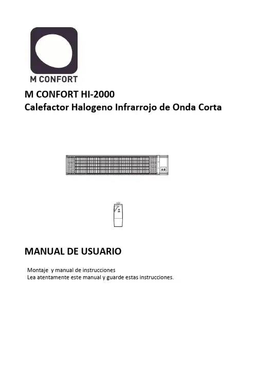
M CONFORT HI-2000Calefactor Halogeno Infrarrojo de Onda CortaMANUAL DE USUARIOMontaje y manual de instruccionesLea atentamente este manual y guarde estas instrucciones.IntroducciónEl calentador de infrarrojos contiene una lámpara de calefacción por infrarrojos y un reflector que proporciona una distribución uniforme del calor.El calentador infrarrojo ahorra 30% -40% de electricidad en comparación con los calentadores tradicionales para terrazas.La temperatura máxima del producto es de 120 gradosAdvertenciaEl calentador de infrarrojos está diseñado para un funcionamiento seguro. Sin embargo, la instalación, mantenimiento y operación del calentador puede ser peligroso para un operador descuidado. Para su seguridad y la seguridad de los demás, por favor, lea las instrucciones de este manual de usuario y siga estas prácticas de seguridad a fin de evitar daños o lesiones.1. Compruebe que el voltaje de la red corresponde a la clasificación del aparato antes de operar.2. No toque las superficies calientes.3. Coloque sobre una superficie plana y estable en el caso de utilizar un trípode.4. Se puede utilizar tanto en sitios cerrados como al aire libre con cuidado de mantener el aparato protegido de la intemperie. Solo se debe utilizar en lugares secos.5. No utilice cerca o en las inmediaciones de la ducha/bañera o en una piscina Solo se debe utilizar en superficies secas.6. Desenchufar de la toma de corriente cuando no esté en funcionamiento.7. Para protegerse contra descargas eléctricas, no sumerja el cable o el enchufe en agua o cualquier otro líquido.8. El uso de accesorios no recomendados por el fabricante del aparato, puede causar graves lesiones.9. Procure tener una distancia adecuada alrededor del calentador para su refrigeración y la ventilación y así evitar cualquier peligro.10. Nunca coloque objetos inflamables o ropa en la parte superior o cerca del calentador.11. No utilice este aparato en las proximidades o cerca de líquidos que sean inflamables o materiales inflamables para así evitar un peligro de incendio. No poner cerca de cortinas, muebles, estanterías, etc.12. No utilice este aparato para otra cosa que no sea su uso previsto.13. No ponga los dedos u objetos extraños en la rejilla mientras esté en funcionamiento.14. No deje el aparato sin vigilancia cuando está en uso.15. Para quitar el enchufe del tomacorriente, no tire del cable. Sujete la clavija firmemente y tire de ella con fuerza.16. No se acepta responsabilidad por cualquier daño causado por el incumplimiento de estas instrucciones o cualquier otro uso indebido del aparato.17. Este aparato es sólo para uso doméstico.18. Este aparato no está diseñado para ser utilizado por personas (incluidos niños) con capacidades físicas, sensoriales o mentales reducidas o falta de experiencia y conocimiento, a menos que una persona responsable de su seguridad les supervise o que estén lo suficientemente instruidos acerca del uso del aparato. Los niños deben ser supervisados para asegurarse de que no jueguen con el aparato.19. Si el cable está dañado de alguna manera, debe ser reemplazado por el fabricante o su agente de servicio o una persona calificada para evitar un peligro.20. Para evitar el sobrecalentamiento de este aparato, mantenga las entradas y salidas de aire limpio y libre de cualquier obstrucción. Revise todas las entradas y salidas de vez en cuando para asegurarse de que esté libre de cualquier suciedad o polvo. NO CUBRIR/TAPAR21. Este aparato no está diseñado para ser operado por medio de un temporizador externo o un sistema de control remoto externo.22. La exposición continua a la radiación infrarroja de alta intensidad en las proximidades podría ser perjudicial para los ojos o la piel. Aunque el tubo de calefacción por infrarrojos no emite radiación electromagnética ultravioleta, puede causar quemaduras si se esta en contacto con el tubo de la calefacción o está operando a una alta intensidad.Debido a la brillante luz que emiten los tubos de calefacción por infrarrojos , se recomienda que los ojos estén protegidos de esta luz, no es aconsejable fijar la vista prolongadamente, si lo va hacer proteja sus ojos con los medios adecuados, Gafas oscuras o de sol.23. Este calentador no está equipado con un dispositivo para controlar la temperatura ambiental. No utilice este calentador en pequeñas habitaciones que están ocupadas por personas que no tengan movilidad para salir de la habitación por su cuenta, a menos que haya una supervisión constante.24. Las partes del calentador pueden superar los 200 ºC. Tocar el tubo de la calefacción, reflector, o las partes metalicas cerca del tubo del calentador , puede causar quemaduras severas25. Nunca coloque las manos debajo de la calefacción. Siempre procure desenchufar el calentador y que se enfríe por lo menos 10 minutos antes de tocar el tubo de la calefacción o partes adyacentes26. Observe que se cumplan todos los códigos eléctricos locales y nacionales y un sistema de tierra eléctrica segura este instalado antes de intentar poner en funcionamiento el calentador. Consulte los procedimientos para una instalación adecuada.27. Este producto contiene materiales reciclables. No deseche este producto como desecho municipal sin clasificar. Por favor contacte a su municipio local para el punto de recogida más cercano.28. Obedezca las mismas normas de seguridad contra incendios que usted observa cuando se trabaja con placas calientes, calentadores infrarrojos de alta intensidad, propano o sopletes de acetileno, soldadores y otros equipos de altas temperaturas.29. Sepa donde se encuentra el extintor más cercano y cómo usarlo.30. Sepa cómo apagar el fuego de todo tipo de material cerca del calentador de infrarrojos.INSTRUCCIONES DE MONTAJEMontado en pared1. Hacer agujeros en la pared donde el calentador se va a montar con un lápiz. Utilice una regla o nivelador para asegurarse de que el calentador esta recto. (Figura 1)2. Taladre los agujeros con una broca de 5 mm. (Figura 1)3. Introduzca el punto final del perno de anclaje a la pared. Clave el anclaje con un martillo hasta que el perno esté al ras con la pared. (Figura 2)4. Utilice una llave inglesa para fijar el soporte de montaje a la pared. (Figura 3)5. Montar al soporte de montaje con el tornillo apretado. (Figura 4)6. Apriete la parte trasera del calentador en el soporte con la tuerca de montaje y con la llave. (Figura 5)El calentador se debe instalar al menos 1,8 m por encima del sueloFUNCIÓN / OPERACIÓNLa tecnología de calefacción por rayos infrarrojos replica los rayos saludables del sol, calentando directamente el objeto o las personas en frente del calentador. A medida quela temperatura de la superficie calentada se eleva, el efecto de calentamiento se siente en todo el ambiente. Estos aparatos son ideales para utilizar en espacios abiertos y en zonas que sean amplias, son equipos que ahorran energía, son seguros y producen un calor sano.No dejan olor, o productos químicos ni humo.1. Conecte la unidad a una toma de corriente. Asegúrese de que la fuente de alimentacióny el equipo tienen el mismo voltaje.2. Pulse el botón de encendido en el lado derecho del calentador3. El indicador luminoso LED muestra el calentador está de espera. (Standby)4. Botón HEAT (ON / OFF) en el panel de control para encender el calentador póngalo en ON. Para apagar el calentador, presione el botón a la posición OFFInspeccione periódicamente su calentador y limpie el equipo de polvo o suciedad periódicamente. De este modo se asegurará de que los equipos funcionan con seguridad. INSTRUCCIONES DE LIMPIEZALa limpieza regular y cuidadosa ayuda a que su calentador de infrarrojos funcione de manera eficiente durante muchos años y sin problemas. Para limpiar la estufa, siga estos pasos:1. Desconecte el cable para su seguridad antes de limpiar el aparato.2. Asegúrese de que el calentador esté frío antes de continuar3. Para mantener el calentador limpio por su parte exterior se puede limpiar con un paño suave y húmedo. Usted puede usar un detergente suave, si fuera necesario. Después de la limpieza, seque la unidad con un paño suave. (PRECAUCIÓN: No deje que los líquidos entran en el calentador)4. No utilice alcohol, gasolina, polvos abrasivos, cera para muebles o cepillos ásperos para limpiar el calentador. Esto puede causar daño y/ o deterioro a la superficie del calentador.5. NO sumerja el calentador en agua6. No trate de desmontar el equipo. Esta tarea queda reservada a los servicios técnicos oficiales.7. Espere hasta que el calentador esté completamente seco antes de usar o de guardar.8. En caso de duda consulte con el fabricanteAlmacenamiento: Almacene el calentador en un lugar fresco y seco, libre de humedades. Cuando no esté en uso, para evitar que el polvo y la suciedad se acumulen utilice su caja de embalaje para guardar su calentador.C/ Catarroja, 1. Oficina 20646940 Manises (Valencia) EspañaAtencion al cliente: +34 961536720SAT:****************。
SERVOPROFIDK2001说明书KONTROL ANALYTIKK2001 TRACE GAS ANALYZERUSER’S MANUAL1.0 关于该⼿册该仪表采⽤“即插即⽤”的思路设计,使⽤简单,本⼿册也简单易懂,操作仪表时不需要了解电路,软件和物理细节等⽅⾯的情况,这正是我们所希望的.我们知道您希望仪表能尽可能快的投⼊使⽤,为此请花时间来通读该⼿册,每⼀章都假设您已阅读和理解了前⾯的章节,每⼀章对⽤户来说都有重要的内容,仪表⾮常容易安装和使⽤并免维护,操作仪表不需特别的技术知识.我们希望您喜欢K2001 氩中微量氮分析仪.为了不断的进步和提⾼.我们⾮常感激您提供有建设性的意见,不管是正⾯的还是负⾯的. Controle Analytique Inc.公司相信该⼿册上所述的信息是正确的.本⽂经过仔细的复查,若有错C.A.公司不须对版本的持有者事先说明.公司保留修改和制作下⼀版本的权利.若发现错误,请与C.A.公司联系,若因为本⽂或其包含的信息的缘故造成的损坏,公司将负全部责任.2.0 忠告2.1 谨防触电只有机箱安全关闭,才能进⾏操作.设备运⾏时有可能导致⾼压电,若接触到会使⼈触电致死或重伤.为了保证仪表的安全和正常运转,交流电源需有地线.维修前报警继电器和数字输出继电器的供电电源需断开.随意更改和替换部件将会影响产品的安全.只能使⽤⼚家许可的部件.2.2 谨防爆炸仪表中除了通氩⽓外,不能通⼊其它⽓体.若易爆,易燃,具腐蚀性的⽓体或混合⽓体进⼊仪表.将会引起起⽕或爆炸.仪表不能在危险区域使⽤.仪表只能安装在实验室环境中,即:⼲燥,⽆振动以及恒温的环境. 2.3 ⾼压⽓瓶的搬运和储存该仪表通常⽤于校验⾼压⽓瓶中的⽓体,⽓瓶的错误操作会使⼈致死或重伤,或造成财产损失.搬运⽓瓶需要格外的细⼼.参见⾼压⽓瓶搬运和储存的注意事项,下⾯⼀些注意事项摘⾃COMPRESSED GAS ASSOCIATION’S HANDBOOK (压缩⽓体协会⼿册).1.绝不能摔⽓瓶或使它们互相剧烈碰撞.2.⽓瓶可以存放在户外,但在这种条件下,必须避开恶劣天⽓.地⾯不能潮湿,以防⽣锈.3.⽓瓶未固定时⼀定要加安全帽.4.要避免拖,滚,滑⽓瓶,即使是⼀⼩段距离也不⾏,需要移动时,应使⽤合适的⼿推车.5.不要更改阀或⽓瓶的安全装置.6.不要把满的和空的⽓瓶放在⼀起,当空的⽓瓶接在增压系统中时,将发⽣严重的倒吸现象.7.⽓瓶温度不得超过1250F(520C),压缩⽓瓶的任何部分不得接近⽕焰.8.不得把⽓瓶接在电路上.电焊时⼩⼼电弧溅向⽓瓶.2.4 安全说明为避免触电,请别移动机箱或打开后盖.⽤户不要对机器内部进⾏修理,修理应由专家进⾏.为避免起⽕或触电,设备要防⾬和防潮.贴有闪电符号的部件表⾯有电,不要触摸它,否则有触电危险.1. 第⼀次使⽤设备前务必要阅读操作⼿册中的安全说明和操作说明.⼿册应放好,以备将来使⽤.2. 安全警告:留意设备及⼿册上的安全警告,按照其要求操作.3. ⽔和⽔蒸⽓:不要有⽔的环境中使⽤,如浴室,⽔盆,下⽔道,洗⾐机,游泳池附近或是潮湿的地下室内.4. 通风:⽆论设备放在那⾥,都需通风.不要置于床上,沙发,地毯或类似易堵住散热孔的物体上.要确保通风以免过热,5. 热效应:不要把设备置于热源附近,如电热器,暖⽓,炉等.6. 电源:电源必须是机器上或操作⼿册上指定的电源.7. 电源插座:注意电线,防⽌践踏,任何东西不得靠近电线,尤其要注意插头,插座以及供电处附近区域.8. 吹洗:吹洗设备遵从制造商建议.9. 不⽤设备:若⼀段时间不使⽤该设备,请把插头从插座上拔下.10. 杂物:确保机箱内没有液体或其它杂物.11. 修理:机器的修理必须由专业⼈员进⾏,除了操作⼿册上允许的维护外,不要擅⾃⾏动.修理⼯作要咨询专家.3.0 承诺及服务本公司承诺:从产品发货⽇起12 个⽉内,仪表在正常使⽤条件下出现的质量问题(不包括易耗品),公司免费维修.易耗品,玻璃电极,膜,液体结合处,电解液,O型圈等在正常使⽤条件下出现质量问题,公司免费维修90 天,⽇期从发货⽇算起.更换,维修的产品和部件以及剩余部分,此承诺同样有效,有效期90 天.当出现问题的产品,部件及消耗品可更新,修理或更换时,⽤户不应提出异议.⾮产品制造质量引起的直接或间接损失,本公司概不负责.服务条例1. 如果在保修期间产品出现问题,公司将免费进⾏维修.超过保修期,顾客需⽀付劳务和材料费⽤.2. 在保修期内,顾客退回产品进⾏维修⽽发现并⽆质量问题,顾客需⽀付最低的维修费⽤.3. 更换部件,原始部件及分析仪的模块号和序列号需提供.若原始部件不送回,C.A 公司将不会寄出更换的部件.仪表返修1. 要返修仪表,⽤户需得到⼀个返修号.2. 提供订单号或其它可接受的资料.3. 遇到的故障连同客户的姓名,地址,电话及返修号列成清单,⼀并寄回.4. 寄回仪表要⽤原始或同样的包装,否则包修⾃动失效.5. 每⼀个⽓体进出⼝⽤封头密封,否则包修⾃动失效.6. 在包装箱外⾯注明返修号.7. 使⽤C.A 公司同意的运输⽅式,空运时货物应直达,不接受中途转运.受其它条件的限制,也可申请海运.商标:本公司采⽤CONTROL ANALYTIK?商标.所有权顾客应认可Controle Analytique 公司对Controle Analytique 的软件,操作系统,硬件及其它商品的所有权.未经Controle Analytique 公司的书⾯允许不得对产品进⾏变换,更改,损坏,改造 ,复制等.4.0 技术指标检测器型号:…………………单光束,电磁感应,等离⼦池,⾮线性测量材料: ⽯英, 单元素. 内部压⼒不超过10PSIG(69Kpa)量程:…………………………X1:0-1ppm 分辨率10ppbX10:0-10ppmx 分辨率0.1ppmX100:0-100ppm 分辨率1ppm精确度:………………………≤1%FS漂移:…………………………±1%/天样品⽓流量要求:……………30~150cc/mm推荐的校验⽓:………………零点⽓:1.0~2.0ppm N2/Ar终点⽓:8.0~9.5ppm N2/Ar注意:校验取决于使⽤的量程。
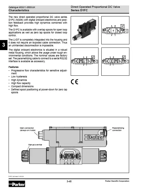
D1FC UK.indd 11.05.233The new direct operated proportional DC valve series D1FC (NG06) with digital onboard electronics and posi-tion feedback provides high dynamics combined with high flow.The D1FC is available with overlap spools for open loop applications as well as zero lap spools for closed loop control.The LVDT is completely integrated into the housing and it does not require an exposed cable connection. Thus an unintended disconnection is impossible.The digital onboard electronics is situated in a robust metal housing, which allows the usage under rough en-vironmental conditions. The nominal values are factory set. The parametrizing cable to connect to a serial RS232 interface is available as accessory.Features• Progressive flow characteristics for sensitive adjust -ment• Low hysteresis • High dynamics • High flow capacity • Compact dimensions• Defined spool positioning at power-down for zero lap spoolsSeries D1FCD1FC UK.indd 11.05.233Ordering CodeDirectSize Propor-Spool1)On power down the spool moves in a defined position. This cannot be guaranteed in case of single flow path on the control edge A – T resp. B – T with pressure drops above 120 bar or contamination in the hydraulic fluid.2)Approx. 10 % opening, only zero lap spools.3)Only for overlap spools.4)Plug in port Y needs to be removed at tank pressure >35 bar. 5)Please order connector separately, see chapter 3 accessories.High D 1F 93CParametrizing cable OBE ® RS232, item no. 40982923Series D1FCD1FC UK.indd 11.05.233Technical Data2) Flow rate for different D p per control edge: Q x = Q Nom. · √D p x D p Nom.1)If valves with onboard electronics are used in safety-related parts of control systems, in case the safety function is requested, the valve elec-tronics voltage supply is to be switched off by a suitable switching element with sufficient reliability.Series D1FCD1FC UK.indd 11.05.233Characteristic CurvesFlow characteristics(set to opening point 10 %) at D p = 5 bar per metering edgeSpool type E01Spool type B31Spool type E50All characteristic curves measured with HLP46 at 50 °C.Spool type B60Series D1FCD1FC UK.indd 11.05.233Frequency± 5 %, ± 25 %, ± 90 % input signalStep responseFunctional limits25 %, 50 %, 75 % and 100 % command signal (symmetric flow). At asymmetric flow a reduced flow limit has to be considered.All characteristic curves measured with HLP46 at 50 °C.Spool type E01KSpool type E01FSpool type E01H Spool type E01C1030F l o w Q [l /m i n ]Pressure drop p P-T [bar]DSeries D1FCD1FC UK.indd 11.05.233Code 511 + PE acc. to EN 175201-804Code 0, 36 + PE acc. to EN 175201-804Code 1, 76 + PE acc. to EN 175201-804 + enableCharacteristic Curves / Block Diagrams3 m length0...±20 mAE:S:Parametrizing cable 3 m lengthItem no.: 409829230...±20 mAE:S:Series D1FCD1FC UK.indd 11.05.233Interface ProgramProPxD interface programThe ProPxD software permits comfortable parameter setting for the module electronics. Via the clearly arranged entry mask the parameters can be noticed and modified. Storage of complete parameter sets is possible as well as printout or record as a text file for further documenta -tion. Stored parameter sets may be loaded anytime and transmitted to other valves. Inside the electronics a non-volatile memory stores the data with the option for recall-ing or modification.The PC software can be downloaded free of charge at /propxd.Features• Comfortable editing of all parameters• Depiction and documentation of parameter sets • Storage and loading of optimized parameter adjust -ments• Executable with all actual Windows ® operating systems from Windows ® XP upwards• Plain communication between PC and electronics via serial interface RS232CThe parametrizing cable may be ordered under item no. 40982923.Series D1FCD1FC UK.indd 11.05.233DimensionsPort Y plugged。
Hardware Manual (03.2*.**)For additional resources, visit our Technical Support site on the web at /ds2000 .•To use the IntraMail enhancements provided by software versions 03.2*.** andhigher, you must use the NEC IntraMail Utility version 1.2 to upgrade your Intra-Mail CompactFlash card. If you don’t upgrade your card, the new features will notbe available.•If upgrading from version 3 software prior to 03.10.08 using telephone program-ming, you must reprogram the options in 1808-IntraMail Subscriber MailboxOptions , 8005-IntraMail Master Mailbox Options , and 8006-IntraMail Rout-ing Mailboxes after the upgrade.•To avoid having to reprogram the above options, use the latest version of theDS1000/2000 System Administrator to backup and restore the site database.•Go to /ds2000 to download the latest versions of the UpdateUtility, IntraMail Utility, System Administrator, and system software.This manual has been developed by NEC Unified Solutions, Inc. It is intended for the use of its customers and service personnel, and should be read in its entirety before attempting to install or program the system. Any comments or suggestions for improving this manual would be appreciated. Forward your remarks to:NEC Unified Solutions, Inc.4 Forest ParkwayShelton, CT 06484Nothing contained in this manual shall be deemed to be, and this manual does not constitute, a warranty of, or representation with respect to, any of the equipment covered. This manual is subject to change without notice and NEC Unified Solutions, Inc. has no obligation to provide any updates or corrections to this manual. Further, NEC Unified Solutions, Inc. also reserves the right, without prior notice, to make changes in equipment design or components as it deems appropriate. No representation is made that this manual is complete or accurate in all respects and NEC Unified Solutions, Inc. shall not be liable for any errors or omissions. In no event shall NEC Unified Solutions, Inc. be liable for any incidental or consequential damages in connection with the use of this manual. This document contains proprietary information that is protected by copyright. All rights are reserved. No part of this document may be photocopied or reproduced without prior written consent of NEC Unified Solutions, Inc.©2005 by NEC Unified Solutions, Inc. All Rights Reserved.Printed in U.S.A.DS2000 Hardware Manual Table of Contents◆iii◆Table of Contents DS2000 Hardware ManualDS2000 Hardware Manual Table of Contents◆iiiiv◆Table of Contents DS2000 Hardware ManualDS2000 Hardware Manual Section 1: Installing the Cabinet◆1-11-2◆Section 1: Installing the Cabinet DS2000 Hardware ManualDS2000 Hardware Manual Section 1: Installing the Cabinet◆1-31-4◆Section 1: Installing the Cabinet DS2000 Hardware ManualTo telcoStationBlocksStationBlocks BlocksFigure 1-3: Removing the CoverSurge ProtectorTo earth groundTo telco groundBlocksBlocksStation BlocksDedicated AC Outlet0000 4 Slot Cabinet ShownMounting the Wall Mount BracketFigure 1-4: Wall Mount BracketFigure 1-5: Mounting the Wall Mount Bracket0000000Using the remaining screws packed with the hanger, secure the cabinet to the plywood backboard.Figure 1-6: Hanging the 4 Slot CabinetFigure 1-7: Hanging the 8 Slot Cabinet80000 - 64 Slot Cabinet ShownFigure 1-8: Removing the Right Side Panel Attaching the Ground Wires!! Important !!You must connect your system to a known earthground according to the following instructions.Figure 1-9: Attaching the Ground WiresTo earth ground For T1 TrunkPCB onlyTo telco groundProper grounding is required.4 Slot Cabinet ShownFor Ground Wires •Required for all installations.For CPU Connections •Required on CPU mod jack and RS-232 cables for allFigure 1-12: Installing the Power SupplyImportant Compatibility Guidelines•Only install Power Supply P/Ns 80005B or 80005C.•Do not install Power Supply P/Ns 80005 or 80005A.•You can mix P/Ns 80005B and 80005C in the same system.•If your system uses UltraMail or UltraMail 2000, you must install only Power Supply P/Ns 80005C.80000 -294 Slot Cabinet ShownFigure 2-2: Setting Up the CPUDigital Station (16DSTU) PCBThe 16DSTU provides the connection for 16 digital telephones. Refer to Section 3, Installing Extensions and for wiring instructions.To install the 16DSTU PCB (Figure 2-4) (Figure 2-5):Plug the 16DSTU PCB for extensions 300-315 into slot CN1.Plug in additional 16DSTU PCBs as required. See System Con figuration on page 1-4 for more.Set the mode switch on each installed 16DSTU PCB to RUN .Figure 2-3: Installing the CPU!! Important !!In a 4 slot cabinet, you cannot install more than 2 16DSTU PCBs.In an 8 slot cabinet, you cannot install more than 2 16DSTU PCBs per power supply.80000 - 304 Slot Cabinet ShownFigure 2-5: Installing the 16DSTU PCBMode switch000Figure 2-7: Installing the ASTU PCBMode switch000Figure 2-8: 16-Port Analog Station (16ASTU) PCB Figure 2-9: Installing the 16ASTU PCBFigure 2-11: Installing the ATRU PCBMode switch Notes:•The system will respond to telco ring signal in the range of 42-103 V AC @ 20 Hz.•Telco battery must be 44-56 VDC.0000A commercially available T1 Tester is recommended.Figure 2-12: T1 Trunk PCB To install the T1 Trunk PCB (Figure 2-13) (Figure 2-14)CN9 to the T1 position.RJ48C ConnectorRS232 PortTelcoSmart JackFigure 2-14: Installing the T1 Trunk PCB 80000-76(Red)WHT-BLU BLU-WHT WHT-ORN ORN-WHT WHT-GRN GRN-WHT WHT-BRN 1234567300 T 300 R 301 T 301 R 302 T 302 R 303 T BLOCK TERM25-PAIR CABLECOLOR CODE FUNCTION RJ61X1Extensions 300-323 Shown8ASTU PCBPCB Location18RJ61X Plug16DSTU PCB134256WHT-BLU BLU-WHT WHT-ORN ORN-WHT WHT-GRN GRN-WHT WHT-BRN BRN-WHT WHT-SLT SLT-WHT 12345678910316 T 316 R 317 T 317 R 318 T 318 R 319 T 319 R 320 T 320 R BLOCK TERM25-PAIR CABLECOLOR CODE FUNCTION RJ61X1Extensions 316-331 Shown16ASTU PCB13424 SlotCabinet Shown1234567 1 T 1 R 2 T 2 R 3 T 3 R 4 T WHT-BLU BLU-WHT WHT-ORN ORN-WHT WHT-GRN GRN-WHT WHT-BRN BLOCK TERM25-PAIR CABLECOLOR CODE FUNCTIONRJ61X123Trunks 1-16PCB Location18N/C 8ATRU PCB8ATRU PCB134562N/CFigure 2-20: Securing the CablesDS2000 Hardware Manual Section 2: PCB Installation◆2-192-20◆Section 2: PCB Installation DS2000 Hardware ManualDS2000 Hardware Manual Section 3: Installing Extensions and Trunks ◆3-10003-2◆Section 3: Installing Extensions and Trunks DS2000 Hardware ManualFigure 3-3: Power Supply Status LEDsDS2000 Hardware Manual Section 3: Installing Extensions and Trunks◆3-3Figure 3-4: CPU Status LEDsFigure 3-5: DSTU, ASTU and ATRU Status LEDs3-4◆Section 3: Installing Extensions and Trunks DS2000 Hardware ManualReattach the two screws that secure the right side panel to the cabinet.4 Slot Cabinet Shown80000 - 16 AFigure 3-6: Reinstalling the Side PanelDS2000 Hardware Manual Section 3: Installing Extensions and Trunks◆3-54 Slot Cabinet ShownA21-8Figure 3-7: Reinstalling the Front Cover3-6◆Section 3: Installing Extensions and Trunks DS2000 Hardware ManualDS2000 Hardware Manual Section 4: Optional Equipment◆4-14-2◆Section 4: Optional Equipment DS2000 Hardware Manual。

微波人体感应智能照明开关产品使用手册型号:DK-001产品参数:工作电压:220V/AC供电频率:50Hz负载功率:500W(最大值)@负载为白炽灯200W(最大值)@负载为荧光灯工作温度:-20℃~ +60℃使用极限温度:-35℃~ +75℃微波频率:ISM 5.8GHz安装高度2m~3.5m建议安装高度:2.5m感应距离:1m~12m可调感应延时:8sec~30min 可调室内安装:吸顶安装感应角度:360°微波输出功率小于10mw 产品尺寸图:产品设置:光感传感器 工作指示灯LN光控设置拨码L1 L2 L3 L4延时设置拨码S5 S6 S7 S8检测等待时间拨码S4 感应距离设置拨码S1 S2 S3拨码开关的使用说明,把开关拨到“ON ”表示“1”,位置在反方向即“OFF ”表示数字“0”,本开关的设置均以数字“0”“1”来表示。
1、光控设置:光控的灵敏度界限从10至2000LUX ,开关的位置和检测范围的对应表格如下:注:光感控制参数说明,当光感设置为≤10LUX 时表示当外界光线强度小于10Lux 时,感应开关才进行人体感应并触发启动灯具工作。
通常≤10LUX 表示为夜间模式,在夜间微波开关才正常启动工作。
当光感设置为2000LUX 时,为白天高照度时微波感应才启动工作的模式。
2、检测距离设置:检测范围是针对固定在离地2.5M 高的感应开关的基础之上,开关的位置和检测范围的对应表格如下:3、检测等待时间设置:检测等待时间就是指当感应开关完成一次检测后,再一次启动功能所需要的时间。
1 0 L1 L2 L3 L4 ILLUMINANCE 0 0 0 0 ≤10LUX1 0 0 0 25LUX0 1 0 0 50LUX 0 0 1 0 150LUX 0 0 0 1 2000LUX 1 0 1 0 1 0 1 0 1 0 1 0 S1 S2 S3 DETECTION RANGE 1 0 0 1m 1 1 0 3m0 0 1 5m1 0 1 8m1 1 1 12m1 0 S4 TIME 1 3.5sec 0 4sec注意事项:1)对感应开关的安装和调试需要专业的电工操作,使用微波感应开关的电器须符合线路安全标准和用电要求,不得带电工作,注意触电!2)本开关不能安装在金属屏蔽物之后,光敏传感器须能够感应到外界光照,不能遮挡。
APS2000 系统说明书APS2000系统手册之使用说明书2007年6月北京柯瑞斯通工程技术有限公司修订记录目录第一章APS2000系统介绍 (7)1、系统简介 (7)2、典型系统架构 (7)第二章APS2000系统安装 (10)1、开始前的准备 (10)2、开始安装 (10)3、启动APS2000系统 (22)4、关闭APS2000系统 (23)第三章APS2000 基本配置 (24)1、APS2000的文件系统 (24)2、APS2000系统主要进程 (26)3 程序的版本与系统注册 (28)4 控制台的设置 (30)5 运行时图形配置 (34)第四章APS2000节点配置 (37)1、APS2000服务器配置 (37)2、APS2000工作站配置 (38)3、APS2000的Mis服务器和Web发布 (38)4、APS2000后台与前置机子系统通信 (41)5、APS2000后台与通信管理机通信 (42)第五章APS2000的主要功能配置指南 (43)1 使用excel进行数据库的导入和导出 (43)2 语音报警的设置 (43)3 历史报警查询的配置 (45)4 变位跳画面和事故跳画面设置 (49)5 APS2000日志的备份 (50)6 事故追忆定义和查询 (51)7 如何重写报警记录 (57)8 和APS2000操作票五防闭锁通讯的配置 (58)9 APS2000和其它厂家五防闭锁通讯的配置 (59)10 如何实现月、季、年统计 (59)11 使用自动计算系数 (60)12 计划曲线的实现 (60)13 遥控与直接控制 (61)第六章APS2000计算表达式 (63)1、概述 (63)2、表达式的引用方法 (63)3、表达式的语法定义 (63)4、列举表达式的一些用例 (74)第七章APS2000数据库管理 (77)1 登陆到数据库管理系统 (77)2 了解数据库管理系统环境 (78)3 数据库的输入和设置 (80)编辑说明:本手册主要针对X86平台及Windows操作系统编写,但绝大部分使用说明在Unix环境下同样适用。
广东科达机电股份有限公司KEDA DYANMO-ELECTRIC CO.,Ltd.目录一、总则二、机械概述三、安全说明四、安装过程五、操作规程六、维护与保养七、用户备件明细表八.随机附件明细表附图一、压机外形图附图二、压机主体附图三、液压部分布局图附图四、喂料部分结构图附图五、顶出部分结构图附图六、模具联接结构尺寸图附图七、液压气动原理图附图八、压制曲线附图九、地基图附图十、压机基础支架1附图十一、压机基础支架2附图十二、冲头开关箱一.总则1.在压机使用之前,操作人员及日常维护人员需经过培训及仔细阅读说明书的全部内容,这样对操作人员、维修人员及设备自身的安全很重要。
本手册中所述的产品及材料会因技术原因或工作原因随时更改,我们保留更改的权利。
说明书的内容属于有价技术资料,不得交付第三方复印或转让。
2.严格按本说明书操作、维护压机,未按本说明书操作、维护产生的不良后果本公司不负责任。
3.用户对说明书必须妥善保管,为便于查阅,说明书应放在靠近设备的地方,使操作和维修人员能在需要的时候及时查阅。
4.对工作循环和机器结构进行的任何修改请向科达集团的产品支持人员咨询,只有他们才有权进行这项工作。
5.压机的使用寿命为10年,本手册也应妥善保管10年以上。
对使用非原装配件导致的设备损坏本公司不承担责任。
6.压机铭牌t)二.机械概述1.设备概述KD2100全自动液压压砖机(以下简称压机)是全自动化设备,专门用于陶瓷墙地砖生产过程中的粉料压制成型。
它由主机部分、液压部分和电气控制部分组成,本机采用液压传动,用可编程控制器实现控制功能。
生产砖坯的粉料一般为喷雾干燥塔生产的颗粒状粉料,含水率一般为6-8%。
压砖的过程是:主活塞带动动梁上下运动,组装在动梁上的上模头对粉料施以压力,压制成型的砖坯由顶出装置顶出模腔,然后布料装置将砖坯推出,由另外的辅机运走, 砖坯被推出的同时, 顶出装置的顶砖缸下降,使模具的下模形成料腔, 布料装置将粉料布入模腔,以备再次压制砖坯。
DKL制动逻辑控制装置使用维修手册前言本产品在出厂前已经过严格检查。
DKL装置购入后,请检查本产品是否因运输不慎而造成损伤;产品的规格、型号是否与订购产品的机种相符;有无合格标志等。
如有问题,请与本公司或供应商联系。
本产品的保修期依照标书约定。
若由于下述原因引起的故障,不属于保修范围:●不正确的操作或未经允许自行修理及改造所引起的问题。
●超出标准规范或未经允许自行修理及改造所引起的问题。
●购买后跌损、野蛮搬运、未按本说明书要求使用造成的问题。
●因环境不良所引起的器件老化或故障。
●为确保设备的良好运行,禁止非专业人员随意打开机箱。
专业人员进行维修时要注意确保人身安全。
目录一、概述二、装置构成三、主要技术参数四、工作原理五、安装与接线六、使用与维护七、故障检修八、附录:各车型接口线号及梯形图一、概述DKL制动逻辑控制装置为电空制动机的电路集成控制装置,尤其适用于DK1制动机控制系统。
该装置采用先进表面贴片(SMT)技术与逻辑控制芯片相结合,取代原制动系统中的迂回电路、阻流板、时间继电器与中间继电器,具有反应速度快、可靠性高、抗干扰能力强、结构紧凑、检修方便等特点;而且具备通过调整软件在相同的硬件上实现不同的逻辑组合功能,以达到控制不同的车型之目的。
DKL制动逻辑控制装置外形图如图一所示。
(此为DKL-SS4G,其它型号类似)图一、DKL制动逻辑控制装置外形图二、装置构成DKL制动逻辑控制装置采用欧式4U标准结构框架,并采用20芯铁路专用连接器实现与机车的信号通讯。
DKL装置(为叙述方便,将DKL制动逻辑控制装置简称为DKL装置)结构图如图2所示。
图二、DKL装置结构图DKL制动逻辑装置由四个部分组成,分别为固定基架、DKL电源板、DKL控制板和DKL输出板。
DKL装置构成外形图如图三所示。
在固定基架前面板部,安装有钮子开关;对应制动系统功能开关,其定义和对应关系见附录。
基架后侧,装有20芯连接器插座,型号:TL02J20ZY;用于实现同外部机车信号联系。
DS2000在线式露点仪操作手册安装及使用前请仔细阅读本手册!本手册包含以下六部分:一、一般描述主要描述分析仪的一般特点及功能二、安装指导安全信息及开封新仪器传感器注意事项传感器安装露点仪安装电子连接外部自动校准控制三、操作指导预热运行前面板显示及按键功能察看预设参数值报警设定重新设定启动的报警值四、DS-2000露点仪的设定自动校准工厂设定参数校验数据、模拟输出,信号补偿及过滤和串口通讯显示颜色、锁定及帮助、报警及指导五、RS485串口通讯数据模式传输协议信息格式六、维护及故障处理一般维护问题解决附表参数及一般图示目录1.0一般描述及参数1.1描述1.2主要性能及特点1.2.1露点仪参数1.2.2传感器参数2.0安装指导2.1安全信息2.1.1警告部分2.1.2绝缘2.2 对新DS-2000露点仪的开封2.3传感器注意事项2.4安装气体取样系统2.5安装传感器2.6安装DS-2000型露点分析仪2.6.1面板安装开孔2.6.2面板安装2.7电子接口连接2.7.1电源供电或选择直流供电2.7.2传感器连接]2.7.3报警继电器输出2.7.4线性(二次输出)输出2.7.5报警开路采集器输出2.7.6串口通讯输出2.7.7外部自动校准控制3.0操作指导3.1分析仪启动3.2前面板现实及按键3.3察看操作模式参数3.4 设置报警和磁滞3.5 磁滞操作3.6 重设报警限度4.0 湿度计设置4.1 传感器校准(自动)4.2 设置程序4.2.1 程序模式4.2.2 结构模式5.0 连续通讯5.1 数据形式/波特率5.2 协议5.3 信息形式5.3.1 信息表15.3.2 信息表25.4 错误情况分析6.0 维修与排除故障6.1 维修6.2 问题指南附录A 产品特性附录B 产品图示1.0一般描述及参数1.1描述DS-2000型露点仪是一种单通道在线精密型露点分析仪,可用于各类工业气体及洁净压缩空气的监测。
分析仪显示单位可在工厂进行灵活的设定,可选择单位℃、℉、ppm(v)、g/m3或者lb/MMSCF显示。