西伯瑞制动器说明书 TE
- 格式:pdf
- 大小:170.98 KB
- 文档页数:6
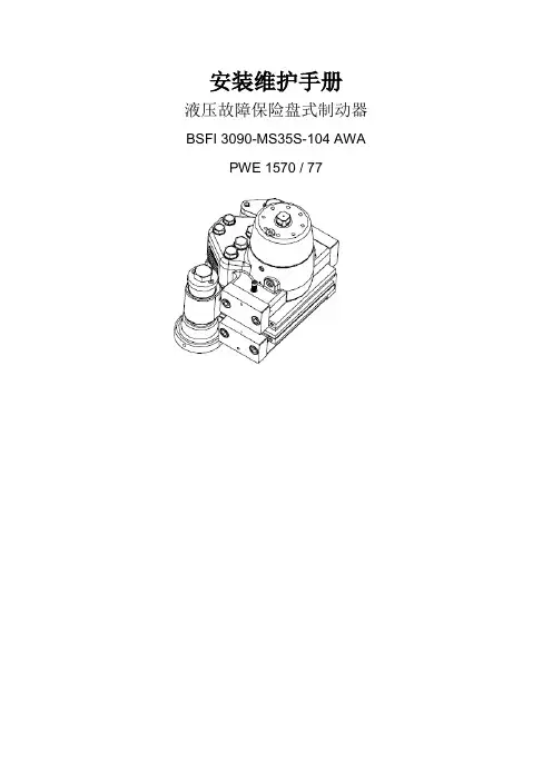
安装维护手册液压故障保险盘式制动器BSFI 3090-MS35S-104 AWA PWE 1570 / 77目录1. 概述 (4)1.1 联系人 (4)1.2 安全 (4)1.3 此手册中的常规惯例 (6)1.4 弃权声明 (7)1.5 换算系数 (7)1.6 铭牌/序号 (8)1.7 制动器是如何工作的。
(10)1.8 功能 (11)1.9 运输 (12)1.10 接口 (13)1.11 润滑 (15)1.12 存放 (16)1.13 处理 (16)1.14 如何采购备件 (17)2. 安装 (17)2.1 吊升和装卸 (17)2.2 清洁制动盘 (17)2.3 清洁安装表面 (18)2.4 装卸/安装制动瓦片 (18)2.5 安装制动器 (21)2.6 检查间隙 (26)2.7 检查制动器的对中调整 (26)2.8 定位系统 (27)2.9 调整定位系统 (29)2.10 制动钳排气和冲洗 (32)2.11 安装指示器 (33)2.12 研磨 (34)2.13 拆下制动器 (35)3. 维护 (37)3.1 指示器 (37)3.2 更换制动瓦片 (37)3.3更换其他部件 (40)3.4 拆下主动制动钳 (41)3.5 更换密封件 (42)3.6 检查弹簧组 (51)3.7 更换弹簧组 (53)3.8 制动器的润滑 (56)4.故障查找 (56)附件A-尺寸图 (60)附件B-装配图,制动器 (61)附件B-装配部件清单,制动器 (62)附件C-备件图,半个制动钳分解图 (64)附件C-备件图,半个制动钳 (65)附件C-备件清单,半个制动钳 (66)附件D-备件图,被动制动钳 (67)附件E-安装图 (68)附件F-定位系统 (69)附件G-“开/关”和“没有调节”指示器 (71)附件H-“瓦片磨损”指示器 (73)附件I-技术参数 (74)附件J-建议使用的流体 (76)附件K-推荐备件 (78)1.概述Svendborg Brakes公司拥有广泛且完整的产品范围,可以为制动器设计者提供了一系列的制动装置,这些装置可以满足关于强大制动的安全性和可靠性以及多用途制动的最高要求。
SETPOINT™ MX2020/WPH and /PSH Weatherproof HousingsMetrix Instrument Company8824 Fallbrook Dr.Houston, TX 77064, USATel: 1-281-940-1802After Hours Technical Assistance: 1-713-702-8805Fax: 1-713-559-9421E-mail:************************Document Number: 1140127Revision: B (Feb 2013)SETPOINT™ MX2020/WPH and /PSH Weatherproof HousingsTable of Contents1 Overview (3)2 What Ships in the Box (4)3 Assembly (6)3.1 Door (6)3.2 T-Handle (7)3.3 Removable Inner Backplate (8)3.4 Grounding Studs (11)3.5 Door-to-Body Ground Strap (12)3.6 Mounting Hole Seals (15)3.7 Power Supply DIN Rail Mounting (15)3.8 Temperature De-Rating (16)4 Specifications (16)SETPOINT™ MX2020/WPH and /PSH Weatherproof Housings1 OverviewMX2020/WPH and MX2020/PSH weatherproof housings are designed to protect SETPOINT monitoring system racks and power supplies from moisture, dust, and (optional) corrosion.∙ MX2020/WPH Weatherproof HousingThis enclosure is designed to house aSETPOINT rack and (optional) accompanying power supplies . The removable door on 18” and 24” models is available with or without the polycarbonate viewing window. The door on 11” models is available as solid metal only.∙ MX2020/PSH Power Supply HousingThis enclosure is designed to house up to two DIN rail-mounted power supplies in aseparate enclosure from the SETPOINT rack. The door is available as solid metal only (no viewing window).All housings meet IP66 requirements. Mild steel housings (painted exterior finish) meet NEMA 4requirements. Stainless steel housings (brushed bare metal finish) meet NEMA 4X corrosion-resistant requirements.Refer to datasheet 1078951 for enclosure ordering information, specifications, outline drawings, and de-rating guidelines for maximum allowable ambient temperatures.SETPOINT™ MX2020/WPH and /PSH Weatherproof Housings 2What Ships in the BoxThe items shipped with each enclosure are summarized below. Some enclosures ship with one or more of these items pre-installed; others ship with all items loose.(table continues on following page)SETPOINT™ MX2020/WPH and /PSH Weatherproof HousingsHardware for affixing DIN rail to backplate(no image)* The plastic standoffs and retaining nuts are shipped together in sealed packets; 2 pcs per packet.SETPOINT™ MX2020/WPH and /PSH Weatherproof Housings3 Assembly3.1 DoorTo facilitate installation of the enclosure and its contents, the door is removable. To remove the door, grip the hinge pins with your fingers or a small pair of pliers and retract them. The figures below show the hinge pins in the locked (left) and unlocked (right) positions. -*+7Hinge pins unlockedpositionHinge pins lockedpositionSETPOINT™ MX2020/WPH and /PSH Weatherproof Housings 3.2T-HandleThe T-handle may or may not be pre-installed on your enclosure door. If it is not pre-installed, slip the included o-ring over the T-handle shaft. Insert the T-handle in the door hole. Install the cam onto the T-handle shaft and secure using the included bolt. The cam can be rotated 90 degrees such that the T-handle is horizontal when locked (left photo) or vertical when locked (right photo), depending on preference.Cam installed in alternate orientation soT-handle is vertical when locked.SETPOINT™ MX2020/WPH and /PSH Weatherproof Housings 3.3Removable Inner BackplateThe removable inner backplate is pre-drilled to accommodate certain combinations of rack sizes and DIN rail-mounted power supplies as summarized below.* These racks fill the entire MX2020/WPH enclosure for the width shown; power supplies must be mountedseparately in enclosure MX2020/PSH.Hole patterns for the MX2020/WPH 24” and 18” backplates are summarized on the following page (11” enclosure hole patterns are not shown; they accommodate a 4-position rack only).SETPOINT™ MX2020/WPH and /PSH Weatherproof HousingsUse Mounting Holes1, 3, 7, 92, 3, 8, 94, 5, 6Use Mounting Holes1, 3, 7, 92, 4, 8, 105, 64 additional holes (one in each corner) are provided but not shown in the above diagrams. They are used for locating the convenience ground stud (see section 3.4.2) in the desired corner.SETPOINT™ MX2020/WPH and /PSH Weatherproof HousingsThe backplate’s hole pattern is symmetrical, allowing the DIN rail to be mounted on the left side or right side of the rack. Normally, the DIN rail should be situated on the left of the rack as shown in the figures above. This places the power supply(ies) closest to the Rack Connection Module (RCM), which always resides in the left-most rack slot.For larger enclosures, the backplate may have double-bent edges along two or all four sides to give it extra rigidity. The bent edges should always face the rear of the enclosure.The rack and (optional) DIN rail should be securely fastened to the backplate before installing the backplate in the enclosure body.** Once the backplate has been placed into the enclosure body and secured, there is not enough clearance around the edges to access rack and DIN rail fasteners from behind.24” MX2020/WPH Enclosure with power supplies on left and 8-positionSETPOINT rack on right.18” MX2020/WPH Enclosure with power supplies on left and 4-position SETPOINT rack on rightSETPOINT™ MX2020/WPH and /PSH Weatherproof Housings 3.4Grounding StudsProper grounding of the enclosure and door is the responsibility of the installer and must adhere to all applicable electrical codes. Four attachment points as detailed in 3.4.1 through 3.4.4 are provided for ground connections:3.4.1 Enclosure Backplate Grounding StudFour (4) threaded studs are welded to the inside back wall of the enclosurebody, allowing attachment of the removable inner backplate. Three studsare painted; one is bare metal (copper clad). Use the copper clad stud forconnecting an external earth ground wire to the enclosure body.3.4.2 Enclosure Door-to-Body Ground Strap StudDetail B in the ground strap hardware packet labels this stud as ①. It is pre-welded to the side wall of the enclosure and usually located in the lower leftfront corner. It is used to attach the door-to-body ground strap discussed insection 3.5. This stud has electrical continuity with the backplate groundstud of 3.4.1. It does not have electrical continuity with the conveniencegrounding stud of 3.4.3 unless a separate jumper strap (not included) isinstalled.3.4.3 Convenience Grounding StudDetail B on the ground strap hardware packet labels this stud as ②.Installation of this stud is optional and provides a post for additional groundconnections to interior electronics. It must use a jumper strap (not included)to tie this post to the stud of 3.4.1. Without a jumper strap, there will not besufficient electrical continuity to tie the post to the earth ground potential ofstud 3.4.1.3.4.4 Door Grounding StudThe door may contain one or more studs similar to 3.4.2, or it may have anunpainted stud where a window bracket* is attached.* The nut is integral (press fit) to the window bracket and may not allow the ground strap to be connectedwithout modification to detach the nut from the bracket. Using the proper tools, the nut can be priedloose from the bracket which will allow attachment of ground strap lug between bracket and nut aspictured at left.SETPOINT™ MX2020/WPH and /PSH Weatherproof Housings 3.5Door-to-Body Ground StrapInstallation instructions are included on the poly bag in which the ground strap components are shipped. The instructions are reproduced on the following pages for convenience in case the bag is damaged or lost. Details B and C show the ground strap connections on the housing and door respectively; however, actual connections may differ from those shown on the bag depending on housing style supplied. Connections for most housings with viewing window doors will instead be as shown in the photos below.CautionThe ground strap provides electrical continuity between the door and the enclosure body, and must be installed. The hinge!Door-to-body ground strap stud will usuallybe located in lower front left corner ofenclosure body.Ground strap connected to window-style door byremoving and re-attaching the window clamp(use only clamp with unpainted stud; all otherstuds are painted and should not be used). Seenote following section 3.4.4 for instructions.SETPOINT™ MX2020/WPH and /PSH Weatherproof HousingsDoor-to-body ground strap hardware packet (instructions from side 1)SETPOINT™ MX2020/WPH and /PSH Weatherproof HousingsDoor-to-body ground strap hardware packet (instructions from side 2)SETPOINT™ MX2020/WPH and /PSH Weatherproof Housings 3.6Mounting Hole SealsThe enclosure body comes pre-drilled with four (4) mounting holes in the back. To ensure these holes maintain an IP66 seal, use the included hole plugs or sealing washers as follows:3.6.1 IF USING THE PRE-DRILLED MOUNTING HOLESWhen mounting the enclosure to a wall or other supports by means of the pre-drilledmounting holes, use the sealing washers shown as item ⑥ in the ground strap hardwarepacket. The black sealing side should face the enclosure. The bare metal side should facethe fastener head.3.6.2 IF NOT USING THE PRE-DRILLED MOUNTING HOLESIf other mounting holes will be drilled (such as on the side of the enclosure), use the holeplugs to seal the unused pre-drilled holes. Four plugs are included (labeled as item ① in theground strap hardware packet).3.7Power Supply DIN Rail MountingPower supplies mount on 35mm DIN rail. For MX2020/WPH enclosures where power supplies will be included in the same housing as the rack, refer to pages 9 and 10 of this manual for pre-drilled hole locations and other considerations. The enclosure ships with DIN rail cut to the correct length, pre-drilled to mate to the backplate, and with all attachment hardware.On MX2020/PSH enclosures, the DIN rail may or may not be pre-installed on the backplate.SETPOINT™ MX2020/WPH and /PSH Weatherproof Housings3.8 Temperature De-RatingElectronic components mounted in a weatherproof enclosure will elevate the temperature inside the enclosure relative to the temperature outside the enclosure. This rise must be accounted for to ensure the electronics do not exceed their maximum rated operating temperature. Use the information in SETPOINT MX2020/WPH datasheet 1078951 to determine the maximum allowable ambient temperature external to the enclosure for a given enclosure size and contents.4 SpecificationsRefer to MX2020/WPH and /PSH product datasheet 1078951 for specifications.!Caution Do not operate the SETPOINT system in conditions that exceed its maximum rated operating temperature of 65°C.Caution Do not locate the enclosure where it will be exposed to direct sunlight. Radiant solar energy will produce higher surface !。
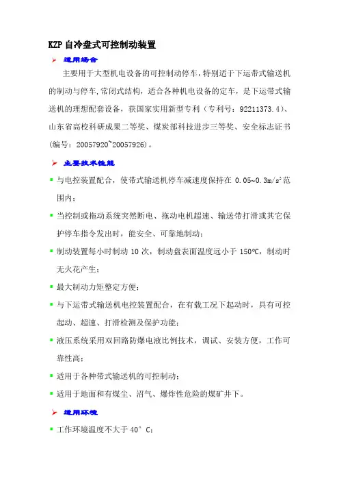
KZP自冷盘式可控制动装置适用场合主要用于大型机电设备的可控制动停车,特别适于下运带式输送机的制动与停车,常闭式结构,适合各种机电设备的定车,是下运带式输送机的理想配套设备,获国家实用新型专利(专利号:92211373.4)、山东省高校科研成果二等奖、煤炭部科技进步三等奖、安全标志证书(编号:20057920~20057926)。
主要技术性能▪与电控装置配合,使带式输送机停车减速度保持在0.05~0.3m/s2范围内;▪当控制或拖动系统突然断电、拖动电机超速、输送带打滑或其它保护停车指令发出时,能安全、可靠地制动;▪制动装置每小时制动10次,制动盘表面温度远小于150︒C,制动时无火花产生;▪最大制动力矩整定方便;▪与下运带式输送机电控装置配合,在有载工况下起动时,具有可控起动、超速、打滑检测及保护功能;▪液压系统采用双回路防爆电液比例技术,调试、安装方便,工作可靠性高;▪适用于各种带式输送机的可控制动;▪适用于地面和有煤尘、沼气、爆炸性危险的煤矿井下。
适用环境▪工作环境温度不大于40°C;▪无显著摇摆和剧烈振动、冲击的场合;▪无足以锈蚀金属的气体及尘埃的环境;▪无滴水、漏水的地方;▪适合煤矿井下要求防爆的场合。
型号意义K Z P-/制动器副数与型号制动盘直径可控盘式制动装置结构特征与工作原理▪组成自冷盘式可控制动装置主要由制动盘,液压制动器(含活塞、闸瓦、弹簧等),底座,液压站等组成。
右图是制动装置在机电系统中的布置示意图,盘式制动装置的制动力是由闸瓦10与制动盘7摩擦而产生,调节10对7的正压力N即可改变制动力,N的大小决定于油压P与弹簧8的作用结果。
当机电设备正常工作时,P达最大值,此时N为0,闸瓦与制动盘间留有1-1.5mm的间隙,即制动器处于松闸状态;当机电设备需要制动时,根据工况和指令情况,电液控制系统按预定的程序自动减小油压P 以达到制动要求。
通常制动盘与减速器某一低速轴相连,也可直接与传动滚筒轴相连实现各种工作制动。
![制动器40366[整理版]](https://uimg.taocdn.com/749fc283dc88d0d233d4b14e852458fb770b38dd.webp)
制动器 (抱闸)机械系统维护调整详细说明1. 制动器的维保应侧重于工作状况的观察、清洁、润滑、检验和制动器的调试。
以下机械部件需要维护:· 制动器磁铁铁心、筒套、定位销、铜垫片。
· 连杆、轴销、轴承、轴瓦。
· 制动臂、闸衬。
· 制动轮、制动杆、制动弹簧、锁母、开口销。
以下电气部件需要维护:· 制动器磁铁线圈、接线。
· 微动开关。
例行检查:一人用时10分钟,进行如下清洁检查:· 查看制动器底部有无因摩擦出现的闸衬粉末。
· 使用吸尘器清除制动器内的灰尘。
· 电梯上下运行时,按下图所示的方法倾听制动器的声响,应无摩擦和撞击声。
· 观察各活动部件及磁铁铁心的动作是否平滑无声;制动器释放时,各活动轴销和铁心能够活动自如。
· 用手触摸制动线圈和制动臂,感受温度。
线圈温升应低于60oC,制动臂温度应为室温。
通过在不同负载条件下乘坐电梯或观察制动时驱动轮的运转状况,可得出制动器存在的问题:1. 如果轿箱空载时制动器抬起过快,则可能发生以下问题:·轿箱上行时将发生碰撞。
· 轿箱下行时先出现上方向溜车。
2. 如果轿箱满载时制动器抬起过快,则可能发生以下问题:· 轿箱上行时,先出现下沉。
· 轿箱下行时,会因重力导致碰撞,然后建立励磁正常工作。
3. 如果制动器动作过慢,则可能发生以下问题:· 轿箱上行时,发生碰撞。
4. 制动器电流不足的典型征兆如下:· 咔嚓声· 拖动· 过载颠簸· 制动轮过热对制动器不恰当的机械和电气调整将导致噪音。
常规维护:每年一次,计划于12月份进行,两人用时90分钟,拆卸、检查、清洁、润滑、调整制动器:1. 停靠轿箱· 将电梯开至顶层置于INDEPENDENT(独立服务)或INS(检修)状态。


A21前制动器总成使用说明书共 6 页编制__刘力平校核季大民审核闵海金伯特利汽车安全系统有限公司2006年3月2.1.2 新制动片总成装配方法用木棒将活塞(14)推压回制动钳体(10) 缸孔内,见右图。
将新制动片总成装在支架(19)中的弹簧片(2)上;然后旋回制动钳;用22~32 N·m力矩拧紧导向销螺钉(16) ,踩制动踏板数次,使两制动片总成与制动盘的间隙合理。
注意:1) 将活塞推压回制动钳缸孔内,制动总泵储油容器中的制动液可能会溢出。
2) 推压回的活塞可能会弹出,这时可用单侧分别更换的方法实施。
3) 制动片总成磨擦面、制动盘磨擦面不得粘附油污。
4)换完制动片将制动片线束(1)连接可靠,确认仪表盘上制动片报警灯熄灭。
2.2 制动钳总成所属零部件的更换2.2.1 零部件的拆卸2.2.1.1 拆下制动油管总成,制动片线束(1)及制动钳固定螺栓(4)。
2.2.1.2 取下两制动片总成(11)。
2.2.1.3 按下图用压缩空气吹出活塞(14)。
2.2.1.4 按右上图挑出矩形密封圈(13)。
2.2.1.5 用乙醇(工业酒精)将制动钳体(10)缸孔内以及两环槽清洗干净,并晾干。
2.2.1.6 将导向销(18)和导向销防尘罩(17)从支架(19)上取下。
注意:1) 用压缩空气吹出活塞时,不允许将手伸进活塞端面的钳口区,否则会压伤手。
请按图示方法拿握制动钳体。
2) 用压缩空气吹出活塞之前,应从进油螺纹孔处倒出制动钳体内的制动液,尽量避免使制动液四处飞溅。
3) 吹出活塞应轻缓,避免拆卸损伤活塞及制动钳缸体。
2.2.2 更换零部件的条件如零件出现下述情况,则必须更换。
制动钳体(10):缸孔磨损变大、缸孔损伤和破裂、钳口断裂性损坏。
活塞(14): 圆滑动面磨损变小、划伤、变形和破裂。
导向销(18):损伤变形、锈蚀。
防尘罩类(12,17):破损。
弹簧片(2):破损。
支架(19):破损、轴销孔磨损、破裂。

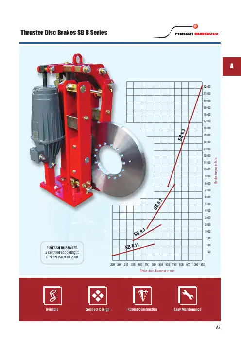
Thruster Disc Brakes SB 8 SeriesA 725028031535540045050056063071080090010001250900080007000600050004000300020001000750 500250B r a k e t o r q u e i n N mBrake disc diameter in mmS B 8.11S B8.1S B 8.2S B 8.3APINTSCH BUBENZER is certified according to DIN EN ISO 9001:2000Description SB 8Data supplied by thruster manufacturer, please take higher start current into consideration, fuses to be minimum 2AThrusters, Technical DataVery compact dimensionsMain FeaturesAutomatic wear compensator OptionsIn combination with long stroke thrusters ideal for conveyor beltsLimit switch release control Limit switch wear control Sintered linings for high friction speeds Limit switch manual releaseManual release lever with or without stop Organic, non-asbestos linings for low friction speedsMonitoring systems (e.g. VSR/CMB)Brake discs with hubs or couplingsAdjustable, enclosed brake spring with torque scaleStainless steel pins and spindlesMaintenance free bushings in all hinge points Right or Left hand designOrdering ExampleA 8A 9AManual release leverRight hand execution Left hand executionAll dimensions in mmAlterations reserved without noticeFor crane brake lay-out use safety factors documented in the FEM 1.001, Section 1identical dimensions)*) Average friction factor of standard material combinationWeight: 37 kg w/o thruster Thruster type Friction factor μ= 0,4*Disc ØFriction Ød 2250280315355d 1195225260300d 4105135170210e 98113130150k 1517693113Bmax 311326343363120140160185200230260300270310355410200230260300Contact force in NEB 120/401550EB 220/502500EB 300/503400Ed 23/52500Ed 30/5Brake torque M Br in NmWeight: 78 kg w/o thruster Thruster type Friction factor μ= 0,4*Disc ØFriction Ød 1275d 4160e 138k 178Bmax 43065511801860Contact force in N EB 300/505950EB 500/60EB 500/12010700EB 800/60EB 800/12016950Brake torque M Br in Nm All dimensions in mmAlterations reserved without noticeFor crane brake lay-out use safety factors documented in the FEM 1.001, Section 1d 2355Right hand execution Left hand executionA 10*) Average friction factor of standard material combination*) If ordered with manualrelease leverRev. 12-06Weight: 180 kg w/o thruster Thruster type Friction factor μ= 0,4*Disc ØFriction Ød 1350400460530d 4200250310380e 175200230265k 1105130160195Bmax 510535565600158018102080239525602930337038803430392045105190Contact force in N EB 500/60EB 500/12011300EB 800/60EB 800/12018300EB 1250/60EB 1250/120245004690536061607100EB 2000/60EB 2000/12033500Brake torque M Br in Nm d 2450500560630Right hand execution Left hand executionA 11A*) Average friction factor of standard material combinationAll dimensions in mmAlterations reserved without noticeFor crane brake lay-out use safety factors documented in the FEM 1.001, Section 1*) If ordered with manualrelease leverWeight: 285 kg w/o thruster Thruster type Friction factor μ= 0,4*Disc ØFriction Ød 1500580670770d 4310390480580e 250290335385k 1170210255305Bmax 61565570075075008600100001150010000116001350015500Contact force in N EB 2000/60EB 2000/12037400EB 3000/60EB 3000/12050200Brake torque M Br in Nmd 2630710800900A 12*) If ordered with manualrelease leverDimension a: With automatic wear compensator max. 280 mmwithout automatic wear compensator max. 220 mmLeft hand executionRight hand execution *) Average friction factor of standard material combinationAll dimensions in mmAlterations reserved without noticeFor crane brake lay-out use safety factors documented in the FEM 1.001, Section 1Weight: 35 kg w/o thruster Thruster type Friction factor μ= 0,4*Disc ØFriction Ød 46085e 7588k 14053145170190220Contact force in NEd 23/52450Ed 23/5bbBrake torque M Br in Nm200225A 13A3150d 1150175Left hand executionRight hand executionMotor or Gearbox vertical mounted*) Average friction factor of standard material combinationAll dimensions in mmAlterations reserved without noticeFor crane brake lay-out use safety factors documented in the FEM 1.001, Section 1。
产品名称:西伯瑞SIBRE抱闸/制动器SIBRE中国代理产品型号:产品报价:5880产品特点:西伯瑞SIBRE抱闸,质量优良,原装进口。
USB制动器以其优异的制动性能和出色的耐久性得到了国内外用户广泛的认可,并成为西伯瑞在中国市场的绝对主力产品;如今西伯瑞的SHI系列安全制动器更是以其“永不漏油"的卓越性能完美诠释了西伯瑞的“Sure to be safe"的产品理念。
西伯瑞SIBRE抱闸/制动器SIBRE中国代理西伯瑞SIBRE抱闸/制动器SIBRE中国代理的详细资料:西伯瑞SIBRE抱闸/制动器SIBRE中国代理SIBREE4N-0311080340305SIBRE3T2204327D ¢315SIBRESIBRE BRAKES 200/300/50(含电力SIBREUSB-3-05-EBC50/30-315X20SIBREUSB3-I-ED50/6 制动器SIBRE制动器TMB400/GH180SIBRETE200/EB 25SIBREV3-PVAL 溢流阀SIBREEB:1250-60II 抱闸推动器SIBRE400/121/6 KOM-NR:140849SIBREV3-CHESIBREUSB3-111-Ed301/6-710*30SIBRESHI 106 MIT KONSOLE UNDCTHV-050/BSZ 252/II 油泵SIBRE带宽1200mm 功率250kw SIBRESK4-M的闸皮SIBRETE300/EB 45SIBRE与SIBRE-0119 配套制动器瓦块SIBREYMZ-500/121ESIBREEMG-ELTMA EB 500-60II SIBREUSB3-I-EB800/60SSIBREUSB-C33-560X30-EB2000/60(右) SIBRETF200-ED30/5SIBRETE250-EB 500/60 415/50HZ SIBREZR336-11Z-M20SIBREUSB3-I-EB800/60-560X30 SIBREMRC2I.182V02A-F0132M4 SIBRESK2-M16 Kom-Nr:127936 SIBREBTF/17500 挠性铰支座SIBREUSB3-I-EB500-60SIBREAFN-SB90-400*30SIBREUSB3-III-ED121/6-1250*30TE200/300/50SIBRE制动器 SHI 107SIBREUSB3-Ⅲ-EB3000/60-710X30 SIBREUSB3-III-121/6-630*30 SIBREUSB3-III-2000/6SIBREUSB3-I-EB300/60SIBREED23/5 推动器SIBRETE630/3000-6SIBREScheibenbreSIBRETMB250-GH160 25% SIBRESB400/180SIBRECTHV-050/BSZ 253/II O型圈SIBREEB:500-60II 抱闸推动器SIBRESHI 201SIBRETMB400-GH180,AC220-240 SIBREDB-3033AF-154-L(左) SIBREUusb3-1 EB800/60 见描述SIBREUSB-I-Ed30/5-400*30 SIBREUSB3-III-Ed201/6-630*30type:SBS250/500/60 no.060368 SIBREEBC 100/30-400VACSIBRE配套制动器USB3-ⅢSIBREGH160.28 D205V ED25/100% SIBREUSB2-II-121/6-500*30SIBRESK2-M16 Kom-Nr:127936SIBRE带宽1200mm 功率90kwSIBRETE630/2000/60 见描述SIBRETE-S200-23-5 MBR 85-400 ED23/5 SIBREUSB3-Ⅲ-800/6SIBRE制动器 SHI25 FA=320KN西伯瑞SIBRE抱闸/制动器SIBRE中国代理SIBREUSB2-II-121/6-630*30SIBRETPI 315/40/80 Nr:134025SIBRETE710-EB3000-60SIBRETE160-EB120/40SIBREV2.1CSIBRESHI252SIBRETA2525CTHV-035-045SIBRE3T2204329D ¢500SIBRE弹簧组件(作用于TE500-ED201/6)SIBREEB300/50 电力液压推动器SIBREED121/6 2LL5 551-1,330W,380V SIBRESBH-S315/500SIBRESHI54 制动器SIBRETE 200-23-5SIBRETE500-EB1250/6,380VAC 50HZ SIBREUUSB3-1 EB800/60SIBREUSB3-Ⅲ/EB1250/60-630*30 SIBRE200*75SIBRE压力开关KC3736SIBREYWZ5-400/E121推动型号Ed121/6 SIBRETYPE:USB2-11-121-6 MBR:4090 SIBRESVN222BE12PDHSS 1008C2 24VDC SIBREUSB3-Ⅲ-2000/6SIBRETE500/1250/60 EZ426 6846-050-1 SIBREUSB-C33-560X30-EB2000/60(左) SIBRETYPE:FE-S400/121/6SIBREV3-PUMSIBRESH1252SIBRE3T2204325D ¢200SIBRETMB 400/GH160 100-1100NM SIBRE带宽1200mm 功率120kw SIBREED201/6 230/400VAC,50HZ SIBRETE200-EB300/50SIBREF3-N A2140SIBRETE400-EB1250/60SIBREV3-GAU油标SIBRECE8-E-100SIBREEB2000-60SIBREUSB-3-I-ED30/S-400*30 SIBREUSB2-05/220/50SIBRESK4-MSIBREUSB3-Ⅲ/EB2000/60SIBRE制动闸瓦,配TEXU500-C使用SIBREUSB3-I-500/60 500-60II SIBREUSB3/I 400*30SIBREED 50/6 推动器SIBREUSB2-11-121-6SIBRE制动器USB3-I-500SIBREAFN-SB125-710*30SIBRETE 200/23/5部件SIBRETE200-ED30/6配套抱闸片(半金属SIBREUSB3-Ⅱ-1250SIBRE刹车片SIBREUSB3-III-Ed301/6-710*30 SIBREED-201/6 推动器SIBREUSB 3/I 400*30SIBRE制动器SHI252SIBREHydraulic,Disk,D1000mm,SH1107, SIBREDB-3033AF-154-R(右)SIBREUSB3-I-Ed50/6-400*30制动力矩SIBRE带宽1400mm 功率315kw SIBRECTHV-050/BSZ 250/II 电磁阀SIBREUSB3-Ⅲ-ED121/6-630*30 SIBRE制动器USB3-Ⅲ/E301/6-800*30 SIBREUSB-III-ED201/6-630*30 SIBRE软制动控制箱SIBRESB400(TE400-EB1250/60) SIBREUSB3-Ⅲ/E201/6/D710*30部件SIBREYMZ-400/121ESIBRE与SIBRE-0060配套的闸皮SIBREEMG-ELTMA EB 1250-60II SIBREGSd 135.6010 126408 FB:1750N SIBREGH165.22-2S Art.Nr:5218070.06 SIBRETE500-ED201/6SIBRETE500-ED201/6S3配套的抱闸片SIBREED 80/6 460 VAC,3phase,60HZ SIBRETE315/500/60SIBRE带宽1400mm 功率2*160 SIBREE-4N H1976SIBREUSB-III-EB1250/60-710*3 SIBRETE250-ED50/6配套抱闸片(半金属SIBREUSB3-111SIBRETE315/800/60SIBRESIBRETE-S400/121 MBR 125-2750SIBREEB3000-60 液力推杆SIBRE制动器SHI 202SIBREUSB3-I-EB500/60-400*30西伯瑞SIBRE抱闸/制动器SIBRE中国代理SIBREEB500/60SIBRETS 100/24U IP55SIBREEB:3000-60II 抱闸推动器SIBRE50-550NmSIBREUSB3-Ⅲ-1250/6SIBRE制动器闸瓦 TE200/23/5部件SIBREUSB3-I-EB500/60SIBREUSB3-III-800/ED121/6SIBRED-35708 HAIGER TYPE:400NM SIBREUSB2-05-EB300/50 415VSIBRE制动器TMB 315/GH160.28SIBRETE400/500/60SIBRETE400/500/60SIBREUSB-3-I-ED50/6-400*30V3-HAND PUMPSIBREGH160.28/5218870104(230VAC SIBREGH160.89 ART.NR:5218060.14 SIBRETE500-EB2000/60 380VAC 50HZ SIBRESTE250/50/6SIBREUSB3-I-50/6-400X30SIBREUSB3-I-EB800/60-500*3SIBRECTHV-050/BSZ 251/II 压力阀SIBREEB300/60SIBREED 50/6 推动器SIBRETE500/2000/60推动型号Ed201/6 SIBREED50/6 推动器SIBREUSB3-I-500-60ifd Nr:14358 SIBREUSB3-III-ED/121/6-630/30 SIBREEB800-60SIBREUSB2-05/220/50SIBREUSB3-Ⅲ/EB1250/60-710*30 SIBREUSB3-111-1250/6SIBRESHI202 NR:141489TE250/30/5 380VAC, 50HZ制动器SIBRE400*150SIBREUSB3-Ⅲ-2000/60SIBRETMB315-GH160.28 25/100%ED SIBREUSB3-I-EB500-30SIBRETE500-EB1250/60SIBRE制动器USB3-Ⅲ/E201/6/D710*30 SIBREED 121/12 460 VAC 60HZ SIBRE制动器USB3-III-2000SIBRETE400/GH160;125-2750NM; SIBRETE250-ED50/6-K1配套抱闸片SIBRED-35708 HAIGER TYPE:USB-1-80/ SIBREZB2500-60SⅡT2MSIBREUSB3-1-80/6 400VAC 3phase SIBREUSB3-Ⅲ-Ed201/6-800*30 SIBRETE500/1250/60SIBRETE400-3/30 D=400SIBRE100-1800NmSIBREAFC-65USB4-II-EB 1250/60*630*30 SIBRETE400-EB800/60SIBREED 23/5 推动器SIBRETE250-EB300/50SIBREUSB3-I-EB800/600 P/N:1 SIBRETE 400/121/6SIBRE带宽1200mm 功率160kw SIBREUSB3-III-2000/60SIBREMD517-G39/06SIBRESHI202 BR:49680.NRRRSIBRETE315/ED80/6SIBRETE630/3000-6SIBRE制动器闸瓦TE315/30 ED50/6部件SIBRE58-400NmSIBREUSB3-1-EB500/60SIBRETMB400-GH180 直流180-220V或SIBRE制动器EBN200-23/5SIBRE制动USB3-I/Ed50/6/D560*30部件SIBREUSB3-III-ED121/6/800*30SHI 106 制动器配套摩擦片SIBRETE 400/121/6SIBRE配套制动器USB3-ⅢSIBRE制动器SHI107SIBREUSB3-I-EB300/50-315*30SIBRETEXU500-CSIBREV3-FIL滤油器SIBRETE315-EB800/60SIBREED 121/6 2LL5 551-1逆止器西伯瑞SIBRE抱闸/制动器SIBRE中国代理。
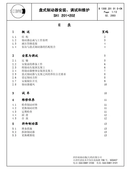
目录1概 述 页码1.1 结 构 2 1.2 制动器总成与工作原理 3 1.3 液压管路连接 4 1.4 泵站与盘式制动器的匹配组合 42 安装与调试 52.1 运 输 5 2.2 安装前的准备工作 6 2.3 将制动头装到支架上 6 2.4 将制动器整体安装到支架上 7 2.5盘式制动器与支架之间的形位公差要求 8 2.6设定制动力矩 8 2.7安装限位开关 9 2.8制动器通风 103试 车104 维修保养114.1 检查制动衬垫 11 4.2 更换制动衬垫 11 4.3 定期检查 11 4.4 润 滑 12 4.5 存 放 125拆卸制动器135.1 准备措施 13 5.2 拆卸制动器 13 5.3 更换碟簧组 131 概 述1.1 结 构SHI系列盘式制动器主要用作中型、重型起重机起升机构和缆机驱动机构的安全制动器,也可用作胶带机等设备的工作制动器,也可能用作夹轨器。
SHI 201松闸压力:115 bar最大工作压力:205 bar每侧碟簧组作用力,松闸时:185 kN碟簧组弹性系数,每mm :约 10 kNSHI 202松闸压力:160 bar每侧碟簧组作用力,松闸时:205 kN每侧碟簧组作用力,松闸时:260 kN碟簧组弹性系数,每mm :约 20 kN技术参数系统最大压力:205 bar活塞面积:177 cm2松闸间隙:(1 - 4)mm最高松闸压力:282 kN油缸最大油容量:0.142 升最长上闸时间:约0.2秒液压油管规格:18 × 2液压站电磁阀流量:100 升/分最长松闸时间:约0.9秒液压站泵流量:9 升/分1.2 制动器总成和工作原理SHI系列制动器是一种弹簧上闸、液压松闸的盘式制动器。
制动器由一对制动头组成,分别装有碟簧组和油缸。
碟簧组支承在机体端盖里,经由活塞、承压板、螺栓和制动靴使制动衬垫压向制动盘,产生制动力,实现制动。
制动时产生的切向力直接传递到带导向法兰的机体上,由机体抵消切向力。
工作原理该系列液压推杆制动器由制动架和相匹配的yt1型电力液压推动器两大部分组成。
当通电时,电力液压推动器动作,其推杆迅速升起,并通过杠杆作用把制动瓦打开(松闸);当断电时,电力液压推动器的推杆在弹簧力的作用下,迅速下降,并通过杠杆作用把制动瓦合拢(抱闸)。
□制动器的安装及调整●制动器安装方式:○纵装:松开螺母4、5使主弹簧处于自由状态,松开6、8螺母,转动螺杆7撑开制动臂,再将制动器套装在制动轮节器9—弹簧座spring base 上。
10—弹簧架刻度机 spring notches ○横装:当制动轮已装在电机与其它机件之间时,松开螺母4、5、6、7、8,转动螺杆取下螺杆3和7,将制动臂放倒。
从侧南装到制动轮上。
●制动器的调整○推动器工作行程的调整在保证闸瓦最小退距的情况下,推动器的工作行程愈小愈理想,因此需要调节其安装高度h1,其调整方法:松开螺母6和8(见图),转动螺杆7,使h1安装尺寸符合表1的要求。
调好后拧紧螺母6、8。
○制动力矩的调整松开螺母4,夹住螺杆的尾部方头,转动螺母5,使方形弹簧座位于弹簧架刻线以内,调整发后将螺母4和5拧紧退即可。
○制动瓦的退距调整当制动瓦打开时,调整螺栓1,使两边退距基本保持一致。
○固定制动瓦的螺母(见图),应松紧适当,使制动瓦与制动轮可以随位。
□使用和维修要定期检查制动器的工作状况。
检查时应着重以下各项:○制动器的构件无能运动是否正常,调整螺母是否紧固。
○推动器的构件是否正常,液压油是否足量。
有无漏油和渗油现象。
引入电线的绝缘是否良好。
○尺寸h1不得小于表1所列之最小尺寸,如超出要求须立即调整,否则失去制动作用。
○制动瓦是否正常的靠在制动轮上,磨擦表面的状态是否完好,有无油腻脏物。
当制动衬垫的厚度达到表2中的数值时,则应更换制动衬垫。
○制动轮的温度不应超过200℃。
○杠杆和弹簧发现裂纹应更换。
篇二:制动器说明书(参考) 1 绪论1.1 课题背景及目的汽车的普及伴随着能源消耗的增多,而如今的生活,汽车已经是人们日常生活离不开的必要工具。
Automatic trailer brake activation,stretch brakeTRB-STRE is a safety system to obtain more secure and sta-ble vehicle combinations. The system gives improved steer-ability and reduces the risk of jack-knifing.When the system is turned on and the accelerator pedal isreleased, it automatically activates the trailer brakes in a pul-sating way. The result is that the trailer is momentarily retard-ed and the vehicle combination is straightened up. In this way,the risk of jack-knifing between the truck and trailer is min-imised and the risk of an accident is reduced.The system is an extra help when driving on slippery andhilly roads, for example when driving downhill with the auxil-iary brake active. Normally in this situation, the truck brakesbut the trailer does not. Furthermore, when only the trailer isbraked, the truckʼs front wheels will maintain full steerability,which is of great importance when driving downhill on curv-ing, slippery roads.The stretch brake is activated with the auxiliary brake stalk,see Driver Guide for details. When the stretch brake is active,an icon is shown in the instrument display. The system can on-ly be activated at low speeds (below 40 km/h).Safety •Safer and more stable vehicle combinations.•Reduced risk of jack-knifing.•Improved steerability on slippery roads.Volvo Trucks. Driving Progress 2023-01-30 ENG Version 05 1 (1)TRB-STRE Stretch brakeVolvo retains the right to modify design and specifications without prior notification.FACT SHEET Trailer brake stretch control PC24 | PCE4。
High Torque Spring Applied Multiple Disc Electric Brakes (HTB)Torque from 5 lb.ft. to 6000 lb.ft.MAXITORQ ®Model HTB brakes are a cost-effective solution whenexceptionally high torque in an extremely small package is required.The HTB brake is released when power is applied to the brake coil.When power to the brake coil is removed, braking torque is applied. The HTB’s modular design, with optional debris cover and optional manual release, provides an “off the shelf” solution to your braking needs, with customization available for unique applications. With low drag torque and minimal power consumption requirements,HTB brakes are extremely efficient. These units also provide fast engagement/disengagement times, especially when assembled with a standard Carlyle Johnson Model CEC power supply.ADVANTAGES• Highest torque in the smallest space • Cost effective solution for exceptionally high torque in extremely small packagesOPERATION• T orque from 5 lb.ft. to 6000 lb.ft.• Floating discs for minimal torque transmission in the disengaged model• Spring set/electrically released for stopping, positioning and holding • Available for wet or dry applications CUSTOMIZATION• Available in multiple voltages • Available with or without manual release• Optional brake friction pad wear indicator switch available • Optional on/off brake status indicator switch available• Optional integral heater for extreme environmental conditions available • Optional sealed cover available • Custom designs and alterations available291 Boston Turnpike, Bolton, CT 06043Main Phone: 860-643-1531 •Fax: 860-646-2645The Carlyle Machine Johnson Company • Phone 860-643-1531 •ModelStatic Torque Locating ØWithout Manual ReleaseWith Manual ReleaseBolt Circle ( lb. ft. )A B C D ØE Thread F HTB027020 2.700.820 2.700 3.150 2.455(4) #8-32HTB035040 3.50 1.500 2.750 3.300 3.215(4) #10-24HTB045095 4.50 2.125 2.950 3.700 4.188(4) #10-24HTB0600220 6.00 2.875 3.550 4.350 5.625(6) 1/4-20HTB08004508.00 3.875 4.125 5.1207.625(8) 1/4-20HTB100090010.004.8754.9606.1609.500(8) 5/16-18-HI J HTB0270 2.875.313(2) #6-32 1.0007/16 or 1/21/8 x 1/16HTB0350 3.700 .313(2) #8-320.9503/4 or 7/83/16 x3/32HTB0450 4.700.500(2) #10-24 1.000 1 or 1 1/81/4 x 1/8HTB0600 6.300.375(2) 1/4-20 1.300 1 1/2 or 1 5/83/8 x 3/16HTB08008.250.625(2) 3/8-24 1.250 2 or 2 1/41/2 x 1/4HTB100010.300.625(2) 3/8-241.7502 1/2 or 2 3/45/8 x 5/16M o d e l H T B - R e v 10/2012Applications & Specifications of High-Torque Spring-Applied Multiple Disc Electric BrakesCarlyle Johnson’s HTB brakes utilize a unique MAXITORQ ®separator spring design, which ensures separation of the rotating friction discs when disengaged. This design virtually eliminates parasitic drag which is detrimental to brake life and will significantly reduce the brake’s overall thermal capacity.Typical applications for HTB brakes include:• Imaging head positioning and holding in medical diagnostic equipment • Stopping and holding in mechanized handling equipment • Servo drive brakes• Holding brakes/emergency stopping brakes for radar antennas • Aerospace and military actuators • Cranes, elevators and escalators • Packaging machineryFor over one hundred years The Carlyle Johnson Machine Company has been at the forefront of innovative power transmission technology. With advanced R&D, precision testing and prototype development we are the industry’s leading resource for effective and efficient power transmission solutions.Our engineering staff is ready to solve your toughest power transmission challenge. We are always just a phone call away.ModelOptional Cover ØG Set Screw LocationSet Screw SizeStandard Bore Size*Keyway。
目录1绪论 (1)1.1制动器的作用 (1)1.2制动器的种类 (1)1.3制动器的组成 (1)1.4对制动器的要求 (3)1.5制动器的新发展 (4)2制动器的结构形式及选择 (6)2.1制动器的种类 (6)2.2鼓式制动器的结构型式及选择 (7)3制动器的主要参数及其选择 (8)3.1汽车整车基本参数计算 (8)3.2轮胎规格计算 (9)3.3制动减速度计算 (10)3.4制动力与制动力分配系数 (10)3.5同步附着系数 (12)3.6制动强度和附着系数利用率 (12)3.7制动器最大制动力矩 (13)3.8摩擦衬片的磨损计算 (14)4 盘式制动器主要参数确定 (16)4.1制动盘直径D (16)4.2 制动盘厚度h (16)4.3 摩擦衬块的内半径R1与外半径R2 (16)4.4 摩擦衬块工作面积A (16)4.5 盘式制动器制动力矩的计算 (16)课程设计的感受 (18)附图 (19)参考文献 (22)1绪论1.1制动器的作用汽车制动系是用于使行驶中的汽车减速或停车,使下坡行驶的汽车的车速保持稳定以及使已停驶的汽车在原地(包括在斜坡上)驻留不动的机构。
汽车制动系直接影响着汽车行驶的安全性和停车的可靠性。
随着高速公路的迅速发展和车速的提高以及车流密度的日益增大,为了保证行车安全、停车可靠,汽车制动系的工作可靠性显得日益重要。
也只有制动性能良好、制动系工作可靠的汽车,才能充分发挥其动力性能。
1.2制动器的种类汽车制动系至少应有两套独立的制动装置,即行车制动装置和驻车制动装置;重型汽车或经常在山区行驶的汽车要增设应急制动装置及辅助制动装置,牵引汽车还应有自动制动装置。
行车制动装置用于使行驶中的汽车强制减速或停车,并使汽车在下短坡时保持适当的稳定车速。
其驱动机构常采用双回路或多回路结构,以保证其工作可靠。
驻车制动装置用于使汽车可靠而无时间限制地停驻在一定位置甚至在斜坡上.它也有助于汽车在坡路上起步。
一、瓦块制动器的组成
块式制动器的主要组成部分(图1)及其功能如下 :
拉 杆 旋转接头
制动臂
制动瓦
底 座
拉杆调节螺母 杠杆板
弹簧组件
推动器
底 座 :有四个安装孔,位置符合DIN 标准。
将制动器安装在底座或者其它结构上, 制动臂: 连接制动瓦、拉杆、杠杆板,制动轮位于两制动臂之间,通过力矩弹簧产生施加制动力。
弹簧组件:由弹簧管、螺杆、弹簧、活塞支板和力矩刻度标组成。
调整弹簧可改变制动力的大小。
推动器: 克服弹簧力,使制动器松闸。
制动器松闸可以用电液、电磁、液压或者气动推动器。
电液推动器构造坚固安全可靠,成为大多数工况的最佳选择。
拉 杆: 将制动力传递到两个制动臂上。
因此,拉杆是制动器中受力最大的部件。
所有SIBRE 制动器的拉杆都采用不锈钢材制成,并采用滚制螺纹。
旋转接头:与拉杆和制动臂铰接,也可以采用销轴连接。
磨损自动 对摩擦片磨损进行补偿。
但是,每个制动循环的补偿量是有限的。
因此, 补偿装置:应根据实际情况,由维修人员手动调整来补偿磨损量。
杠杆板: 弹簧组件和推动器都连接在杠杆板上,以此实现小行程大作用力。
插图 1
插图 2
拉杆调节螺母
三、从制动轮的一侧进行安装
1.旋转拉杆调节螺母,使制动瓦 间距比制动轮直径大5毫米。
2.将底座销1从制动臂中拉出。
3.抬起左侧制动臂。
4.将底座置于制动轮下方。
5.调整制动器到正常位置(对 制动器进行径向和轴向调整)。
6.放下制动臂,用销轴1将其固 定在底座上。
7.安装推动器。
8.固定底座。
9. 制动器所有轴杆的对中公差为: max. +/- 0.3 mm.
插图 3
插图 4
插图 5
制动臂
底座销 1 底 座
推动器
拉杆调节螺母
拉 杆
四、制动器的调试方法
1.推动器断电,制动器上闸。
2.旋转拉杆调节螺母,调整推动器 的补偿行程X 。
(图6)
3. 旋转弹簧调节螺母,设定制动力矩。
制
动力矩可以从刻度标上读出(以弹簧支 板的上沿为基点)。
必要时应重新调整补 偿行程X(图6+7)。
4. 由于采用等退距机构,不必进行等间隙调节(见图8)。
即: - 两侧摩擦片间隙相等; - 安装过程中制动器自动对中; - 无需调节制动臂限位挡块;
- 摩擦片磨损后,制动器结构仍然稳定。
五、补偿装置的调整方法:
(图 9)
1. 将驱动销尽可能向下推入。
2. 旋出杠杆板上的调节螺钉,露出导 向孔。
3. 用推动器使制动器开合数次,然后合闸。
4. 将调节螺钉旋入杠杆板,使调节螺钉和
驱动销之间约有0.2mm 的间隙。
紧固防 松螺母(图 9)。
注意:摩擦片磨损补偿装置的作用是对摩擦片的磨损量进行补偿,
而每个制动循环的补偿量是一定的。
因此,必须根据具体情况由维护人员手动来调整补偿量。
插图 6
插图 7
拉杆调节螺母
补偿行程: 20% 推动器行程
弹簧调节螺母
弹簧管
力矩标尺 插图 8
等退距机构
插图 9
调节螺钉 防松螺母 驱动销 导 孔
六、制动瓦更换方法
更换制动瓦时,不必拆卸制动器,步骤如下:
1.旋转拉杆调节螺母,拧出拉杆,即可进行制动块的更换;
2.松开制动瓦夹紧弹簧,取出制动瓦销轴(图10);
3.取出旧制动瓦;
4.安装新制动瓦;
5.重新紧固夹紧弹簧;
6.重新调试制动器。
插图 10
制动瓦销轴制动瓦夹紧弹簧
七、配件明细
6
8
序号名称
1 2 3 4 5 6 7 8 制动瓦成套
摩擦片(带铆钉)销轴成套
衬套成套
弹簧组件
拉杆成套
推动器
摩擦片磨损自动补偿
订购备件时,请告知:
制动器型号:如 TE400/80/6
铭牌上的制造序号:如 009576
数量,序号和名称:如 2 件,6号,拉杆成套。