冲压中多工件的最佳排样
- 格式:doc
- 大小:286.50 KB
- 文档页数:20
冲压排样技巧《冲压排样技巧之我见》嘿,各位朋友!今天咱来聊聊这冲压排样技巧,这可真是一门有意思的学问呢!你说这冲压排样,就像是给那些金属板材安排一场特别的“舞蹈”。
要让它们在这场“舞蹈”中,既能跳得精彩,又能最大限度地节省“场地”,不浪费一丝一毫。
想象一下,那些板材就像是一群调皮的小孩,咱得想办法把他们安排得妥妥当当的。
要我说啊,这冲压排样的第一个技巧就是“精打细算”。
咱得像个小气鬼一样,计算好每一块板材的尺寸和形状,怎样才能让它们拼得最紧密,浪费最少。
可不能大手大脚地随便排,那可不行!咱得把每一寸板材都利用到极致,让它们发挥出最大的价值。
然后呢,就是要有点“创意”。
不能老是走寻常路,得学会来点花样。
比如说,把那些形状奇怪的板材巧妙地组合在一起,就像拼图一样。
有时候,你得打破常规思维,才能找到最优的排样方案。
这就好比是一场头脑风暴,你得让你的脑袋瓜子转得飞快,想出一些别人没想到的点子。
还有很重要的一点,那就是要“随机应变”。
可别一套方案走天下,不同的板材、不同的要求,就得有不同的排样方法。
就像去不同的场合得穿不同的衣服一样,得合适才行。
有时候遇到难题,就得赶快想办法调整,不能死脑筋。
我记得有一次,遇到一块特别难搞的板材,怎么排都觉得不合适。
当时我那叫一个头疼啊,差点就想放弃了。
但咱不能轻易认输啊,于是我静下心来,重新审视那块板材,突然灵机一动,想到了一个新的排样方法,嘿,还真就给解决了!那一刻的心情,简直比吃了蜜还甜。
总之啊,这冲压排样技巧既是一门技术,也是一种艺术。
咱得用心去琢磨,去实践,才能掌握其中的奥秘。
让那些金属板材在咱的指挥下,乖乖地排列整齐,为我们创造出更多的价值。
这就是我对冲压排样技巧的一些真实感受和见解,希望能给大家带来点启发和乐趣。
哈哈,让我们一起在冲压排样的世界里快乐地玩耍吧!。
Die Life of cold stamping die and improvementsOverview of stamping dieStamping Die - Stamping in the cold,the material (metal or non-metallic)processing into parts (or half)of a special technical equipment, called cold stamping die (commonly known as Die). Press - is at room temperature, using the die installed in the press to put pressure on the material to produce a separation or plastic deformation,and thus to obtain the necessary parts of a pressure processing method。
Stamping die in the form of many,the general categories according to the following main features:1. According to the technical nature of(1)Die along the closed or open contour the material are derived from mold. If blanking die,punch die, cut off the mold, cut mode, cutting mode, split mode, etc。
(2) bending mode to blank or blank sheet along a straight line (curved line)to bend,deform, and thus obtain a certain angle and shape of the workpiece in the mold。
附录A冲压中多工件的最佳排样摘要:在冲压生产中,生产成本受材料利用率影响最大,材料支出占整个生产成本的75%。
本文将介绍一种新的计算方法用于实现双工件在冲压排样设计中的最佳规划方法,以便提高材料利用率。
这种计算方法可以预示在带料中结构废料的位置及形状,以及工艺废料的位置和最佳宽度。
例如将两个相同的工件中的其中一个旋转180°,或是将两个不同的工件嵌套在一起。
这种计算方法适合与冲模设计CAE系统结合使用。
关键字:冲压,模具设计,最佳化,材料利用率,明可夫斯基和,设计工具绪论在冲压生产中,能够快速生产不同复杂程度的薄片金属零件,特别是在大产量的情况下,能够高强度生产。
生产过程效率高,其中材料成本占据整个冲压生产成本的75% [1]。
但材料不能被完全利用到零件上,因为零件不规则的外形必须被包含在带料内。
冲压生产的排样设计直接决定废料的大小。
很明显,使用最理想的排样设计对于提高公司的竞争力是至关重要的。
前期工作曾经, 带料排样设计问题需要通过手工来解决。
例如, 通过纸板模拟冲裁来获取一个好的排样方法。
通过计算机介绍的设计过程所得出的步骤。
也许首先要做出适合工件的矩形,然后将矩形顺序排放在带料上[2]。
这种方法适合不相互重叠的矩形[3]、拉深多边形[4, 5]、已知相互关联的外形[6]。
这种原理的方法具有一定局限性,尽管如此,在这种具有局限性下的设计中所产生较多的工艺废料不能被避免,这些额外损失的材料导致了设计方案无法达到最佳化。
增量旋转法是一种流行的排样设计方法[6-10, 16]。
具体实现方法为,将零件旋转一定的角度,例如2°,[7],在设计中决定零件倾斜程度和带料宽度以及合适的材料利用率。
在不断重复这些步骤以后工件旋转量达到180º (由于对称),然后从中选出最佳排样方法。
这种方法的缺点是,在一般情况下,最佳材料定位将降低旋转增量同时不能被找到。
尽管差别很小,但在大批量生产中每个零件所浪费的材料会累计进而导致较多材料损失。
冲压件如何设计排样,分享几种常见的排料图冲压件生产的成本最主要就是原材料的费用,据统计在冲压件中原材料费用占整个产品成本的60%以上,因此合理的利用材料是冲压件生产中一个非常重要的问题。
冲压件在钢带或者钢板上的布置方法叫做冲压排样。
如果排样设计的不合理就会造成材料的浪费。
确定排样是否合理主要是参考材料的利用率,也就是工件的实际面具于材料面具的百分比。
减少废料的产生面积,那么材料的利用率就比较高。
废料分为工艺废料和结构废料2种。
搭边和余料属于工艺废料,这是和排样方式以及冲压方式有关的废料。
结构废料是由工件的形状和特点决定的。
提高材料利用率,应该从减少工艺废料着手,设计合理的冲压排料方案。
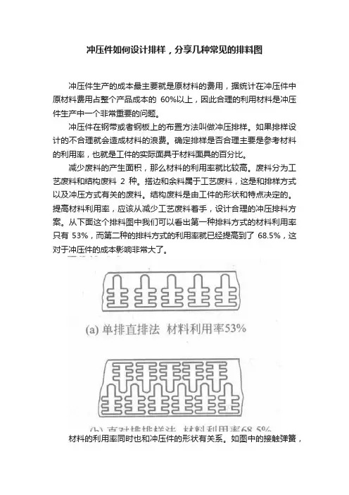
从下面这个排料图中我们可以看出第一种排料方式的材料利用率只有53%,而第二种的排料方式的利用率就已经提高到了68.5%,这对于冲压件的成本影响非常大了。
材料的利用率同时也和冲压件的形状有关系。
如图中的接触弹簧,原来的形状材料利用率只有41%。
在保证孔距的情况下,如果将产品的外形做修改,材料的利用率就可以提高到92.5%,极大的降低了产品成本。
所有在客户允许的情况下,也可以考虑改变冲压件的外形。
如图所示,冲压件的排料可以分为有废料排样、少废料排样和无废料排样这三种排料方式。
采用少、无废料排样,对于降低冲压件成有着重大意义,而且有利于同时冲压多个产品,提高了生产效率。
同时因为冲压周长减少,可以简化冲压模具的结构和降低冲压力。
无废料排样的材料利用率可以达到95%,少废料排样的材料利用率也可以达到70%-90%。
图中是几种常见形状冲压件的排料方式,大家在设计冲压排料的时候可以参考下。
精密五金冲压件,排样设计原则详解
排样设计,是生产精密五金冲压件之前的一个重要准备工作,合理的排样系统有主与提高冲压件质量和生产效率,还有助于保护模具,延长其使用寿命。
很多刚入行的操作员可能不太了解,诚瑞丰冲压厂为您解答。
精密五金冲压件排样设计的原则主要遵循以下几点:
1.在冲压加工中,为了提高材料的利用率,可根据
2.原材料的宽度来选择单排或多排的设计方式。
3.所设计的弯曲件,其毛刺应位于工件的内侧,既对品质影响不大,也不会损
伤外观。
4.在模具设计时,要预留足够的间隙,尤其是应对拉深工艺,拥有备用的工位
意味着更方便拉深工艺施展。
5.在模具上正确安装导正销,通过更精准的定位作用,生产出更标准的冲压件。
6.观察金属原料的展纹方向,因为这种结构会影响到排样的效果和设备性能。
7.切勿在冲压加工时在模具表面留有废料。
8.在图纸设计时要进行反复试样,再安排冲孔、切废料等工序。
9.增加侧刃压边工序,对于薄料增加导向装置,不进行切边处理;对于厚料需
要切边,避免导正销出现切边现象。
高质量高效率地生产出精密五金冲压件,是我们的追求。
诚瑞丰公司,24年专注生产冲压件,20000+套冲压模具生产经验,月产100+套模具,上百台精密加工设备,日500万冲次生产产能,冲压精度可达0.01mm,18道质检层层严格把关,欢迎联系合作!。

![[说明]多工位精密级进模排样设计应遵循的原则](https://uimg.taocdn.com/44acfa18b42acfc789eb172ded630b1c59ee9bd5.webp)
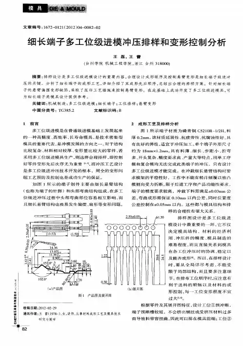
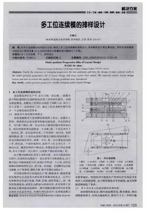
排样设计应遵循的原则多工位级进模的排样,除了遵守普通冲模的排样原则外,还应考虑如下几点:1)可制作冲压件展开毛坯样板(3~5个),在图面上反复试排,待初步方案确定后,在排样图的开始端安排冲孔、切口、切废料等分离工位,再向另一端依次安排成形工位,最后安排制件和载体分离。
在安排工位时,要尽量避免冲小半孔,以防凸模受力不均而折断。
2)第一工位一般安排冲孔和冲工艺导正孔。
第二工位设置导正销对带料导正,在以后的工位中,视其工位数和易发生窜动的工位设置导正销,也可在以后的工位中每隔2~3个工位设置导正销。
第三工位根据冲压条料的定位精度,可设置送料步距的误送检测装置。
3)冲压件上孔的数量较多,且孔的位置太近时,可分布在不同工位上冲出孔,但孔不能因后续成形工序的影响而变形。
对相对位置精度有较高要求的多孔,应考虑同步冲出,因模具强度的限制不能同步冲出时,后续冲孔应采取保证孔相对位置精度要求的措施。
复杂的型孔,可分解为若干简单型孔分步冲出。
4)为提高凹模镶块、卸料板和固定板的强度和保证各成形零件安装位置不发生干涉,可在排样中设置空工位,空工位的数量根据模具结构的要求而定。
5)成形方向的选择(向上或向下)要有利于模具的设计和制造,有利于送料的顺畅。
若有不同于冲床滑块冲程方向的冲压成形动作,可采用斜滑块、杠杆和摆块等机构来转换成形方向。
6)对弯曲和拉深成形件,每一工位变形程度不宜过大,变形程度较大的冲压件可分几次成形。
这样既有利于质量的保证,又有利于模具的调试修整。
对精度要求较高的成形件,应设置整形工位。
7)为避免U形弯曲件变形区材料的拉伸,应考虑先弯成45°,再弯成90°。
8)在级进拉深排样中,可应用拉深前切口、切槽等技术,以便材料的流动。
9)压筋一般安排在冲孔前,在凸包的中央有孔时,可先冲一小孔,压凸后再冲到要求的孔径,这样有利于材料的流动。
10)当级进成形工位数不是很多,制件的精度要求较高时,可采用压回条料的技术,即将凸模切入料厚的20~35%后,模具中的机构将被切制件反向压入条料内,再送到下一工位加工,但不能将制件完全脱离带料后再压入。
「模具技术」五金冲压连续模具的排样技术在五金、家电及日用工业品生产中,作为主导工艺之一的板料冲压加工,节能降耗具有巨大的潜力有待挖掘。
其中,节省原材料就有很大的空间和潜力。
据近年来在全国电器开关、农机、家电及仪表行业的调研,冲压板材料利用率大致在62.5%~73.5%之间。
随着日甚的市场竞争,原材料的售价,跟着能源价格节节攀升而大幅上涨,节省原材料已成为冲压加工中紧迫的节能降耗任务,是相关企业降低成本、增加效益的有效途径,也是增强产品市场竞争力的重要手段。
从表1 可以看出,在成批和大量生产中,如果将冲压材料利用率η 提高 1%,冲件成本将下降 0.4~0.5 个百分点。
排样及连续冲压的排样图设计原则平板冲裁件(含各种成形冲件的展开平毛坯—下同)落料前,为节省材料,在板、条、带、卷料上进行经济而合理的排列布置,以获取最佳排样,达到尽可能高的材料利用率。
在冷冲压工艺设计和冲模设计工作中,这是一项重要而技术性很强的工作;在冷冲模结构设计中,冲压件图、冲压工艺及其排样图是主要依据。
在已知的专业出版物中,都对冲裁件落料即单工位冲裁模、复合模冲件排样给予详尽介绍,对于多工位连续模冲件的排样不曾涉足。
多工位连续冲压件的排样图,要充分表示出冲压工艺及冲压工步的顺序,标注出送料进距、沿边、搭边的具体数据及工位间送进方式和冲压冲件的全部冲压工艺及变形与分离过程。
排样图与模具的选型、结构设计、冲压材料利用率η、冲压生产率和冲件生产成本密切相关,同时也影响到冲压件的质量和模具寿命。
排样时要充分考虑材料供应的状况及冲压设备的生产条件,在保证冲件质量的基础上,力争冲模具有更佳的结构,更好的操作安全性与制模工艺性,要全面综合分析影响排样的各种因素,进行多方案比较,从中选优而确定出最佳排样。
冲模设计开始前要通过分析冲件图和排样图,了解其主要技术要求和冲压加工难点,对照其排样图审定其冲压工艺的合理性和可能存在的问题,以便为冲模结构设计打下基础。
冲压加工工序顺序安排原则
冲压加工是借助于常规或专用冲压设备的动力,使板料在模具里直接受到变形力并进行变形,从而获得一定形状,尺寸和性能的产品零件的生产技术。
板料,模具和设备是冲压加工的三要素。
冲压加工是一种金属冷变形加工方法。
所以,被称之为冷冲压或板料冲压,简称冲压。
它是金属塑性加工(或压力加工)的主要方法之一,也隶属于材料成型工程技术。
冲压工序顺序是指冲压加工过程中各道工序进行的先后次序。
冲压工序的顺序应根据工件的形状、尺寸精度要求、工序的性质以及材料变形的规律进行安排。
一般遵循以下原则:
(1)对于带孔或有缺口的冲压件,选用单工序模时,通常先落料再冲孔或缺口。
选用级进模时,则落料安排为最后工序。
(2)如果工件上存在位置靠近、大小不一的两个孔,则应先冲大孔后冲小孔,以免大孔冲裁时的材料变形引起小孔的形变。
(3)对于带孔的弯曲件,在一般情况下,可以先冲孔后弯曲,以简化模具结构。
当孔位位于弯曲变形区或接近变形区,以及孔与基准面有较高要求时,则应先弯曲后冲孔。
(4)对于带孔的拉深件,一般先拉深后冲孔。
当孔的位置在工件底部、且孔的尺寸精度要求不高时,可以先冲孔再拉深,这样有助于拉深变形,减少拉深次数。
(5)多角弯曲件应从材料变形影响和弯曲时材料的偏移趋势安排弯曲的顺序,一般应先弯外角后弯内角。
(6)对于复杂的旋转体拉深件,一般先拉深大尺寸的外形,后拉深小尺寸的内形。
对于复杂的非旋转体拉深尺寸的应先拉深小尺寸的内形,,后拉深大尺寸的外部形状。
(7)整形工序、校平工序、切边工序,应安排在基本成形以后。
1、目的:为规范公司冲压件坯料排样设计、提高材料利用率,特编制本规范。
2、适用范围:本文件适用于冲压件落料方案的设计。
3、引用标准:无4、规范要求排样方案优化有利于显著提高材料利用率。
使用零件制造所需材料的净重与总毛重的比例来表示实际材料利用率。
要求净重>0.3kg的零件实际材料利用率>50%。
否则首先需要检查排样方案是否最优,然后检查冲压工艺设计是否合理。
为了提高计算下料边线的准确性与排样方案的合理性,请按照以下流程进行排样方案制作:4.1 下料边线的计算4.1.1 零件展开基准选择零件展开必须使用零件的中面作为基准面。
中面位于零件厚度1/2的位置,可以使用UG等CAD 软件抽中面功能获取中面。
4.1.2展开参数设置零件的展开线实际是用多段较短直线或曲线去拟合一条较长的连续曲线,因此网格划分直接影响展开计算的准确性,特别是圆角部位的网格。
要求零件圆角部位必须覆盖有3排以上网格,即圆角部位网格尺寸<1/3*圆角半径。
零件其它位置网格大小请参考表1。
表1 零件尺寸与网格大小对照表4.2 排样参数设置搭边尺寸为零件展开线与板料边界的距离。
零件间距为排样中零件之间的距离。
设置排样基本参数请参考表2。
版本:A0焊接夹具设计标准更新日期:表2 排样基本参数设置材料厚度T<2.5mm 2.5<T<5mm5<T<12mm搭边尺寸(2.0~3.0)*t(2.5~4.0)*t(0.75~0.9)*t零件间距(2.0~3.0)*t(2.5~4.0)*t(0.75~0.9)*t零件长度越大,搭边尺寸和零件间距取值应越大;零件间距取值可略小于搭边尺寸。
采用等离子切割时,零件间距与搭边尺寸取值为5mm。
4.3坯料余量选择当零件的冲压采用成型工艺时,根据零件形状可适当将零件展开线单边放大0~10mm的余量,作为后序修边等精加工余量。
当零件的冲压采用拉延工艺时,根据零件形状可将零件展开线单边放大0~30mm的余量。
冲压中多工件的最佳排样摘要在冲压生产中,生产成本受材料利用率影响最大,材料支出占整个生产成本的75%。
本文将介绍一种新的计算方法用于实现双工件在冲压排样设计中的最佳规划方法,以便提高材料利用率。
这种计算方法可以预示在带料中结构废料的位置及形状,以及工艺废料的位置和最佳宽度。
例如将两个相同的工件中的其中一个旋转180°,或是将两个不同的工件嵌套在一起。
这种计算方法适合与冲模设计CAE系统结合使用。
关键字:冲压,模具设计,最佳化,材料利用率,明可夫斯基和,设计工具绪论在冲压生产中,能够快速生产不同复杂程度的薄片金属零件,特别是在大产量的情况下,能够高强度生产。
生产过程效率高,其中材料成本占据整个冲压生产成本的75% [1]。
但材料不能被完全利用到零件上,因为零件不规则的外形必须被包含在带料内。
冲压生产的排样设计直接决定废料的大小。
很明显,使用最理想的排样设计对于提高公司的竞争力是至关重要的。
前期工作曾经, 带料排样设计问题需要通过手工来解决。
例如, 通过纸板模拟冲裁来获取一个好的排样方法。
通过计算机介绍的设计过程所得出的步骤。
也许首先要做出适合工件的矩形,然后将矩形顺序排放在带料上[2]。
这种方法适合不相互重叠的矩形[3]、拉深多边形[4, 5]、已知相互关联的外形[6]。
这种原理的方法具有一定局限性,尽管如此,在这种具有局限性下的设计中所产生较多的工艺废料不能被避免,这些额外损失的材料导致了设计方案无法达到最佳化。
增量旋转法是一种流行的排样设计方法[6-10, 16]。
具体实现方法为,将零件旋转一定的角度,例如2°,[7],在设计中决定零件倾斜程度和带料宽度以及合适的材料利用率。
在不断重复这些步骤以后工件旋转量达到180º (由于对称),然后从中选出最佳排样方法。
这种方法的缺点是,在一般情况下,最佳材料定位将降低旋转增量同时不能被找到。
尽管差别很小,但在大批量生产中每个零件所浪费的材料会累计进而导致较多材料损失。
梅塔-启发式优化方法适用于排样设计,包括模拟退火[11, 12]和初步设计[13]。
当解决较复杂设计问题时 (也就是在2D平面上将较多不同零件嵌套在一起),它不能保证最佳排样方法,但是可以根据获得的计算结果进而总结为一个较好的解决方法。
开发出一种在设计过程[15]中确定单一零件在带料上的布局以及带料的宽度的确定[14]的精确的最佳的计算方法。
这些计算方法基于建筑几何学中一个外形从另外一个上‘发展’出来。
相似的理论在这个学科中基于一个名叫‘无适合多边形’,‘障碍空间’和‘明可夫斯基和’创建。
从根本上来讲,它仅是一种解决位置关系的方法,这样的外形有缺陷,但不会重叠。
通过这种方法的应用 (本文中,特殊的译文是指明可夫斯基和),能够创建一种全球化的最佳的具有高效率的排样布局的计算方法。
对于排样设计中零件间布局的特殊问题则根据问题报告采用增加旋转计算方法[7, 16]和模拟退火 [11],但是迄今为止并没有能够被实际应用的精确的计算方法。
在下文中,将简要介绍明可夫斯基和,以及它在带料排样设计中的应用,和它在成对零件间嵌套问题的延伸的描述。
明可夫斯基和零件的外形被近似嵌套在每个多边形的n 个顶点上,在CCW方向上有限连续。
随着顶点数量的增加零件边上的弯曲刃口能够近似的得到任意想要达到的精确度。
例如两个多边形,A 和 B,明可夫斯基和详细说明了A和B上每一个顶点的总和。
(1)表面上看, 令人联想到这种方法中的零件A‘成长于’零件B,或是变化后的零件–B (也就是零件B旋转180°) ,零件A周围和接着零件B周围参考点所连接而成的轨迹。
例如,图1所示零件A。
如果基于其中一个参考顶点 (0,0),将旋转180°后的零件A (也就是–A)围绕着零件A,–A上的参考点以粗线描述出图2中所示轮廓。
这个轮廓即是麦克马斯特和。
麦克马斯特和计算所用的方法能够被创建在计算出的几何图形中如[17,18]。
(图1)示例零件A被嵌套(图2)示例零件(虚线)在麦克马斯特和(粗线)中。
这个方法的意义在于如果–A的参考顶点是在的周界上,A和–A将会相接触但不会产生重叠。
两个零件将会尽可能的紧密贴合在一起,因而在设计时将一对零件其中的一个旋转180°。
定义了一对零件间所有可行的位置关系。
这个性质的一个推论是如果单一零件的麦克马斯特和是合适的。
那么该零件将被否定,也就是。
(麦克马斯特和推出的一个完整的说明[15]。
)这些报告是根据带料上单一零件间的最佳嵌套计算方法得出。
嵌套的成对零件太过复杂的情况时,不仅要作出零件的最佳定位和选定带料宽度还要设计成对零件间最佳的位置关系。
为了解决这一问题,故提出一种重复运算方法:假设:零件A和B(B=–A,–A即将A旋转180°)5. 在不干涉A的情况下选择B的位置关系麦克马斯特和定义了可行的位置关系 (图2)。
6. 在这个位置关系中‘加入’A和B. 创建出新的组合零件外形C。
7. 在带料上使用麦克马斯特和套入组合零件C以及[14]或[15]给出的运算法则。
8. 重复步骤1-3直到排列出所有A和B可能的位置关系。
在每个位置关系中找出最好的位置关系,如果这样,数字上最佳的位置关系即是最高的材料利用率。
两相同零件间最佳设计方法上述方法的第一步是选择一个可行的B和A的位置关系。
上的一个平移矢量t定义了这个位置,如(图3)所示。
当这个平移矢量t穿过的轮廓时为最佳的方法。
(图3)上关系零件的平移节点,显示出平移矢量t。
最初,节点上不连续的数被放置在中的每个边界上。
每个平移节点描述了两个零件临时‘加入’位置关系,然后组合零件带料宽度中的最佳位置上使用单件生产设计程序(例如在 [14]或[15]中)。
在此例中, 由12条边组成,每条边包含10个节点,总共多达120个平移节点。
每个节点的位置是通过每条边直线的插补创建,在麦克马斯特和上即顶点I的坐标是(,)。
定义一个位置参数中s = 0和中s = 1,每个平移节点的坐标创建方式如下:(2)(3)如果点m放置在每条边上,,位置参数的值,按如下公式创建:(4)利用图3所示120个节点计算出的结果如图4所示。
在此图中,当每条边移动时显示了如何利用截线改变每条边后平移矢量的线被打断。
当一些边的截线上述单一的变化,其他截线的则显示了2到3个局部截线。
从中找最合适的位置,这就是需要许多节点的原因。
(图4)零件 A 和–A的最佳材料利用率根据创建出的级数,当局部最大利用率被显示出时即可调用一个理论上最佳的方法。
在引出工作利用率之前不可用(无附加计算结果),可以使用区间分半法 [19]。
节点最初组成的间距能够显示出局部最大的点。
三个相同间距的点放置在上述间距间 (也就是在 1/4, 1/2和3/4 的位置),然后计算出每个点上的利用率。
比较每个点上的利用率之值,能够根据反复降低所得间隔的一半得出结果。
上述步骤直到得到想要的精度为止。
应用这种方法推导出最佳平移矢量点 (747.894,250.884),如(图5)所示排样图材料利用率达92.02%。
有趣的是,较好的设计看起来成对零件能够更加的贴近,以便提高材料利用率。
(图5)单一零件A的最佳排样方法不同零件同一带料上的最佳排样方法生产中常遇到相同材料和相同产量的各类零件,例如,需要装配在一起的左右两部分零件。
将类似的零件组合在一起生产可以获得更高的效率,还能提高材料的利用率。
这种运算法则的排样设计同样适合相同零件的排样设计。
例如(图6)所示的零件B。
决定平面位置关系的相应的麦克马斯特和,如(图7)所示。
在此例中, 包含15条边,材料利用率的值如(图8)所示。
重复一次,通过的边精确显示出多种局部最大利用率。
(图9)所示即为最佳排样平移矢量点坐标(901.214, 130.314)。
材料利用率为85.32%。
此例中带料宽度为1229.74、步距为1390.00。
(图6)被嵌套的示例零件B(图7)示例零件(细线和虚线)的麦克马斯特和(粗线)(图8)示例零件A和B不同排样方法的材料利用率(图9)示例零件A和B的最佳排样方法结论在冲压工作中,材料成本占产品成本很大比重,所以即使每个零件上微小的节约,也能累计成可观的价值。
本文介绍了一种新的创建零件间嵌套的最佳排样计算方法。
这种计算方法利用了麦克马斯特和计算出成对零件间所有可行的位置关系,和选取零件最佳位置以及带料的宽度。
做排样设计时应注意:所有的排列方式都应该被考虑。
例如,本文中示例零件的排样方法应该考虑:零件A单独排样成对生产,零件B单独排样成对生产以及A和B成对一起生产。
设计者应该考虑原料成本,模具加工成本和操作成本以及冲出零件需要的工具尽量降低生产成本。
这种计算方法的应用还可以拓展,其中一个显而易见的拓展应用即是零件间旋转后的最佳位置关系,即改变零件B在带料上相对于零件A的位置。
另一个拓展是可以更深入的学习函数的运用。
Stamping Die Strip Optimization for Paired PartsAbstractIn stamping, operating cost are dominated by raw material costs, which can typically reach 75% of total costs in a stamping facility. In this paper, a new algorithm is described that determines stamping strip layouts for pairs of parts such that the layout optimizes material utilization efficiency. This algorithm predicts the jointly-optimal blank orientationon the strip, relative positions of the paired blanks and the optimum width for the strip. Examples are given for pairing the same parts together with one rotated 180º, and for pairs of different parts nested together. This algorithm is ideally suited for incorporation into die design CAE systems.Keywords: Stamping, Die Design, Optimization, Material Utilization, Minkowski Sum, Design ToolsIntroductionIn stamping, sheet metal parts of various levels of complexity are produced rapidly, often in very high volumes, using hard tooling. The production process operates efficiently, and material costs can typically represent 75% of total operating costs in a stamping facility [1]. Not all of this material is used in the parts, however, due to the need to trim scrap material from around irregularly-shaped parts. The amount of scrap produced is directly related to the efficiency of the stamping strip layout. Clearly, using optimal strip layouts is crucial to a stamping firm‟s competitiveness.Previous WorkOriginally, strip layout problems were solved manually, for example, by cutting blanks from cardboard and manipulating them to obtain a good layout. The introduction of computers into the design process led to algorithmic approaches. Perhaps the first was to fit blanks into rectangles, then fit the rectangles along the strip[2]. Variations of this approach have involved fitting blanks into non-overlapping composites of rectangles [3], convex polygons [4,5] and known interlocking shapes[6]. A fundamental limitation exists with this approach, however, in that the enclosing shape adds material to the blank that cannot be removed later during the layout process. This added material may prevent optimal layouts from being found.A popular approach to performing strip layout is the incremental rotation algorithm [6-10,16]. In it, the blank, or blanks, are rotated by a fixed amount, such as 2º[7], the pitch and width of the layout determined and the material utilization calculated. After repeating these steps through a total rotation of 180º (due to symmetry), the orientation giving the best utilization is selected. The disadvantage of this method is that, in general, the optimal blank orientation will fall between the rotation increments, and will not be found. Although small, this inefficiency per part can accumulate into significant material losses in volume production.Meta-heuristic optimization methods have also been applied to the strip layout problem, both simulated annealing [11, 12] and genetic programming [13]. While capable of solving layout problems of great complexity (i.e. many different parts nested together, general 2-D nesting of sheets), they are not guaranteed to reach optimal solutions, and may take significant computational effort to converge to a good solution.Exact optimization algorithms have been developed for fitting a single part on a strip where the strip width is predetermined [14] and where it is determined during the layout process [15]. These algorithms are based on a geometric construction in which one shape is …grown‟ by another shape. Similar versions of this co nstruction are found under the names …no-fit polygon‟, …obstacle space‟ and …Minkowski sum‟. Fundamentally, they simplify the process of determining relative positions of shapes such that the shapes touch but do not overlap. Through the use of this construction (in this paper, the particular version used is the Minkowski sum), efficient algorithms can be created that find the globally optimal strip layout.For the particular problem of strip layout for pair s of parts, results have been reported using the incremental rotation algorithm [7, 16] and simulated annealing [11], but so far no exact algorithm has been available. In what follows, the Minkowski sum and its application to strip layout is briefly introduced, and its extension to nesting pairs of parts is described.The Minkowski SumThe shape of blanks to be nested is approximated as a polygon with n vertices, numbered consecutively in the CCW direction. As the number of vertices increases, curved edges on the blank can be approximated to any desired accuracy. Given two polygons, A and B, the Minkowski sum is defined as the summation of each point in A with each point in B,(1)Intuitively, on e can think of this process as …growing‟ shape A by shape B, or by sliding shape –B (i.e., B rotated 180º) around A and following the trace of some reference point on B. For example, Fig.1 shows an example blank A. If a reference vertex is chosen at (0, 0), and a copy of the blank rotated 180º (i.e., –A) is slid around A, the reference vertex on –A will trace out the path shown as the heavy line in Fig.2. This path is the Minkowski sum. Methods for calculating the Minkowski sum can be found in computationalgeometry texts such as [17, 18].Sample Part A to be Nested.Minkowski Sum (heavy line) of sample Part (light line).The significance of this is that if the reference vertex on –A is on the perimeter of , A and –A will touch but not overlap. The two blanks are as close as they can be. Thus, fora layout of a pair of blanks with one rotated 180º relative to the other, defines all feasible relative positions between the pair of blanks.A corollary of this property is that if the Minkowski sum of a single part is calculated. Withits negative, i.e.,. (A complete explanation of these properties of the Minkowski sum is given in [15].) These observations were the basis for the algorithm for optimally nesting a single part on a strip.The situation when nesting pairs of parts is more complex, since not only do the optimal orientations of the blanks and the strip width need to be determined, but the optimal relative position of the two blanks needs to be determined as well. To solve this problem, an iterative algorithm is suggested:Given: Blanks A and B (where B=–A when a blank is paired with itself at 180º)1. Select the relative position of B with respect to A. The Minkowski sumdefines the set of feasible relative positions (Fig.2).2. …Join‟ A and B at this relative position. Call the combined blank C.3. Nest the combined blank C on a strip using the Minkowski sum with the algorithm given in [14] or [15].4. Repeat steps 1-3 to span a full range of potential relative positions of A and B. At each potential position, evaluate if a local optima may be present. If so, numerically optimize the relative positions to maximize material uti lization.Layout Optimization of One Part Paired with ItselfThe first step in the above procedure is to select a feasible position of blank B relative to A.This position is defined by translation vector t from the origin to a point on, as shown in Fig.3. During the optimization process, this translation vector traverses theperimeter of.Relative Part Translation Nodes on, showing Translation Vector t.Initially, a discrete number of nodes are placed on each edge of. The two parts are temporarily …joined‟ at a relative position described by each of the translation nodes, then the combined blank is evaluated for optimal orientation and strip width using asingle-part layout procedure (e.g., as in [14] or [15]). In this example, consists of 12 edges, each containing 10 nodes, for a total of 120 translation nodes. The position ofeach node is found via linear interpolation along each edge, where is vertex Ion the Minkowski sum with a coordinate of (,). Defining a position parameter ssuch that s = 0 at and s = 1 at, coordinates of each translation node can be found as:(2)(3)If m nodes are placed on each edge,,the position parameter values for thenode, , are found as:(4)Calculating the utilization at each of the 120 nodes on Fig.3 gives the results shown in Fig.4. In this figure, the curve is broken as the translation vector passes the end of eachedge of to show how utilization can change during the traversal of each edge.While some edge traversals show monotonic changes in utilization, others show two or even three local maxima. Discovering these local optima is the reason why a number of translation nodes are needed.Optimal Material Utilization for Various Translations Between Polygons A and –A.As a progression is made around, when local maxima are indicated, a numerical optimization technique is invoked. Since derivatives of the utilization function are not available(without additional computational effort),an interval-halvingApproach was taken [19]. The initial interval consists of the nodes bordering the indicated local maximal point. Three equally-spaced points are placed across this interval (i.e. at 1/4,1/2 and 3/4 positions), and the utilization at each is calculated. By comparing the utilization values at each point, a decision can be made as to which half of the interval is dropped from consideration and the process is repeated. This continues until the desired accuracy is obtained.Applying this method to the example leads to the optimal translation vector of (747.894, 250.884), giving the strip layout shown in Fig.5, with a material utilization of 92.02%.Interestingly, while it appears that the pairs of parts could be pushed closer together for a better layout, doing so decreases utilization.Optimal Strip Layout for Part A Paired with Itself.Layout Optimization of Different Parts Paired TogetherVery often parts made from the same material are needed in equal quantities, for example, when left-and right-hand parts are needed for an assembly. Blanking such parts together can speed production, and can often reduce total material use. This strip layout algorithm can be applied to such a case with equal ease. Consider a second sample part, B, shown in Fig.6. The relevant Minkowski sum for determining relative position translations,, is shown in Fig.7. In this case, contains 15 edges, whose utilization values are shown in Fig.8. Again, multiple local maxima occur while traversing particularedges of. The optimal layout occurs with a translation vector of (901.214, 130.314), shown in Fig.9, giving a utilization value of 85.32%. Strip width is 1229.74 and pitch is 1390.00 in this example.Sample Part B to be Nested.Minkowski Sum (heavy line) of Sample Parts (light and dashed lines).Optimal Material Utilization forVarious Translations Between Polygons A and B.ConclusionsIn the stamping operation, production costs are dominated by material costs, so even tiny per-part gains in material utilization are worth pursing. This paper has presented a new algorithm for creating optimal strip layouts for pairs of parts nested together. This algorithm takes advantage of the Minkowski sum calculation to both find feasible relative positions between the pairs of parts, and to determine the optimal orientation and strip width for the strip layout.When evaluating combinations of layouts, it should be kept in mind that all permutations should be considered. For example, the strip layout process for the sample parts in this paper would consider strip layouts for A alone, A paired with itself, B alone, B paired with itself, and A and B paired together. The designer would then consider total raw material costs, tooling construction costs and press operating costs since blanking parts together requires larger tools and presses and changes production rates.There are opportunities to extend this algorithm, as well. One obvious extension is to include optimization over relative rotations between the pairs of parts, i.e., changing the orientation of part B relative to A on the strip. A second opportunity is to study the utilization function more deeply.References1. Industry Canada, 1998 “Industry Overview Reports: SIC-E 3253 – Motor Vehicle Stampings Industry,” Ottawa, Canada, November 22, 1998.2. Adamowicz, M. and Albano, A., 1976, “Nesting Two-Dimensional Shapes in Rectangular Modules,” Com puter Aided Design, Vo1.8, pp.27 – 33.3. Qu, W. and Sanders, J.L., 1987, “A Nesting Algorithm for Irregular Parts and Factors Affecting Trim Losses,” International Journal of Production Research, Vo1.25,pp.381–397.4. Dori, D. and Ben Bassat, M., 1984, “Efficient Nesting of Congruent Convex Figures,” Communications of the ACM, Vo1.27, pp. 288–235.5. Karoupi,F. and Loftus, M., 1991, “Accommodating Diverse Shapes within Hexagonal Pavers,” International Journal of Production Research, Vo1.29, p p. 1507–1519.6. Chow, W. W., 1979, “Nesting of a Single Shape on a Strip,” International Journal of Production Research, Vo1.17, pp. 305–322.7. Nee, A. Y. C., 1984, “A Heuristic Algorithm for Optimum Layout of Metal Stamping Blanks,” Annals of the CIRP, Vo1.33, pp. 317–320.8. Prasad, Y. K. D. V. AND Somasundaram, S., 1991, “CASNS: An Algorithm for Nesting of Metal Stamping Blanks,” Computer Aided Engineering Journal, Vo1.8, pp. 69–73.9. Prasad, Y. K. D. V., Somasundaram, S. and Rao, K. P., 1995, “A Slid ing Algorithm for Optimal Nesting of Arbitrarily Shaped Sheet Metal Blanks,” International Journal of Production Research, Vo1.33, pp. 1505–1520.10. Lin, Z. C. and Hsu, C. Y., 1996 “An Investigation of an Expert System for Shearing Cut Progressive Die Des ign,” International Journal of Advanced Manufacturing Technology, Vo1.11, pp. 1–11.11. Jain, P., Feynes, P. and Richter, R., 1992, “Optimal Blank Nesting Using Simulated Annealing,” Trans. of the ASME Journal of Mechanical Design, Vo1.114, pp.160–165.12. Theodoracates, V. E. and Grimsley, J.L., 1995, “The Optimal Packing ofArbitrarily-Shaped Polygons using Simulated Annealing and Polynomial –Time CoolingSchedules,” Computer Methods in Applied Mechanics and Engineering, Vo1.125, pp.53–70.13. Ismail, H. S. and Hon, K. K. B., 1992, “New Approaches for the Nesting of Two Dimensional Shapes for Press Tool Design,” International Journal of Production Research, Vo1.30, pp. 825–837.14. Joshi, S. and Sudit, M., 1994, “Procedures for Solving Single-pass Strip Layout Problems,” IIE Transactions, Vo1.26, pp. 27–37.15. Nye,T.J.,2000,“Stamping Strip Layout For Optimal Raw Material Utilization” Journal of Manufacturing Systems, Vo1.19, pp. 239–248.16. Choi, J. C., Kim, B. M., Cho, H. Y. and Kim, C., 1998, “A Compac t and Practical CAD System for Blanking or Piercing of Irregular-Shaped Metal Products and Stator and Rotor Parts,” International Journal of Machine Tools and Manufacture, Vo1.38, pp. 931-963.17. De Berg, M., Van Kreveld, M., Overmars, M. and Schwarzkopf, O., 1997 Computational Geometry: Algorithms and Applications.Springer, Berlin.。