SICK安全继电器UE410连接指南
- 格式:pdf
- 大小:162.55 KB
- 文档页数:4
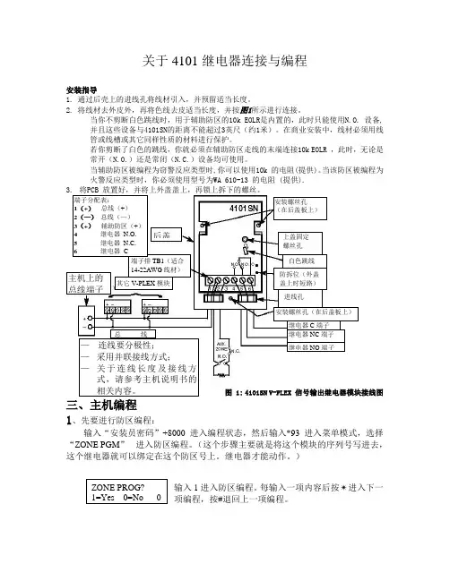
关于4101继电器连接与编程安装指导1. 通过后壳上的进线孔将线材引入,并预留适当长度。
2. 将线材去外皮外,再将色线去皮适当长度,并按图1所示进行连接。
当你不剪断白色跳线时,用于辅助防区的10k EOLR 是内置的,此时只能使用N.O. 设备, 并且这些设备与4101SN 的距离不能超过3英尺(约1米)。
在商业安装中,线材必须用线管或线槽或其它同样性质的材料进行保护。
若你剪断了白色的跳线,你就必须在辅助防区走线的末端连接10k EOLR ,此时,无论是常开(N.O.)还是常闭(N.C.)设备均可使用。
当辅助防区被编程为窃警反应类型时,你可以使用10k 的电阻(提供)。
当该防区被编程为火警反应类型时,你必须使用型号为WA 610-13 的电阻 (提供).图 1: 4101SN V-PLEX 信号输出继电器模块接线图三、主机编程 1、先要进行防区编程:输入“安装员密码”+8000 进入编程状态,然后输入*93 进入菜单模式,选择“ZONE PGM ” 进入防区编程。
(这个步骤主要就是将这个模块的序列号写进去,这个继电器就可以绑定在这个防区号上。
继电器才能动作。
)输入1进入防区编程。
每输入一项内容后按✴进入下一项编程,按#退回上一项编程。
安装螺丝孔(在后盖板上)防区号码 (Zn): 输入想编程的防区号码1-128,例如输入010。
按*继续出现目前该防区的编程情况按照类型含义列表输入合适的防区类型。
这里输入03(周边)按 *接收输入。
输入所在的子系统号码,这里输入1, 按 ✴接收输入。
输入该防区报告码,不联网的主机可以不输,按✴接收输入。
输入输入设备类型:这里输入06总线设备,按*接收输入。
输入设备类型 06 将出现此提示,输入1 监视维护信号(如 5192SD, 5192SDT, 5808),否则输入 0.,按 *接收输入。
输入设备类型 06 将出现此提示,输入1 是使用 4101SN 等继电器模块,否则输入0.,按*接收输入。

IDM1xx_2xx配对设置及Profinet通讯手册类型:调试指导版本:V1.0 日期:2017-5-26目录1.手持读码器类型 (3)2.硬件连接 (3)3.手持枪的供电及状态说明 (4)3.1.手持枪供电 (4)3.2.手持枪指示灯状态及含义 (4)4.手持枪设置连接模式 (6)4.1.无线蓝牙手持枪支持的PICO、PAIR模式 (6)4.2.PAIR模式 (6)4.3.DPM功能激活 (7)5.手持抢参数设置 (7)6.CDF600-2200设置 (9)6.1.硬件设置 (9)6.2.软件设置 (10)7.PLC通讯设置 (10)7.1.下载GSDML文件 (10)7.2.添加GSD文件 (12)7.3.设备组态并设置CDF600-220x (13)7.4.通讯字符握手说明 (14)7.5.通讯字符握手设置 (15)1. 手持读码器类型本操作手册针对以下产品中除IDM142 WIFI、IDM162 WIFI型外其他所有接口为RS232型手持式条码阅读器。
2. 硬件连接我公司Profinet网关有两种型号,本文中以常用型号CDF600-2200为例,设备连接方式如下图所示:3. 手持枪的供电及状态说明3.1. 手持枪供电3.2. 手持枪指示灯状态及含义4. 手持枪设置连接模式4.1. 无线蓝牙手持枪支持的PAIR 、PICO模式PAIR模式表示手持枪主体和底座为一对一连接,为最通用模式;PICO模式为手持枪主体和底座为一对多连接。
一个蓝牙底座最多支持7个手持枪主体。
4.2. PAIR模式4.3. DPM功能激活(可选)5. 手持抢参数设置按照以下表格从上往下扫描:顺序内容条形码1 恢复出厂默认设置2 设置为RS232通讯模式3 进入设置模式设置波特率为96004设置STX/ETX为前后缀56 设置数据位格式为:n,8,1.7 删除CR结束符8 结束设置如果有条件,建议先把手持枪底座与电脑通过RS232进行通讯连接,打开串口监控工具,查看数据格式是否已经设置成功。

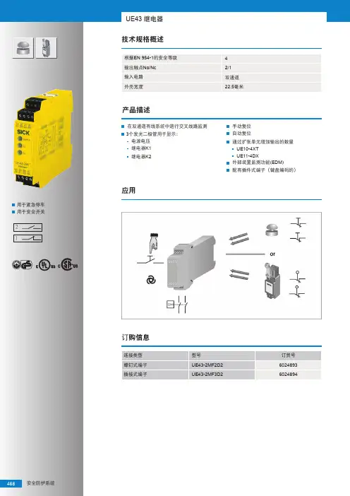
PNOZ X3P产品描述安全继电器PNOZ X3P被封装在一个45mm p-99的塑壳里面。
该装置可以接24 (240)VAC/DC.的电源使用。
DescriptionThe Safety Relay PNOZ X3P is enclosed in a45 mm P-99 housing. The unit can beoperated with 24 ... 240 VAC/DC.特点•继电器输出:3对常开触点和一对辅助触点。
Positiveguided型触点。
(指采用机械方式联接使常开和常闭触点永远不能同时闭合的触点)•接线连接包括急停按钮、安全门限位开关、复位按钮。
•状态指示灯。
•扩展接触器/继电器的状态监视•晶体管有输出表明装置已备妥。
继电器兼容以下安全标准要求:•电路是含有内置自检功能的冗余设计--符合EN 954-1•在自身组件失效的情况下安全功能仍然起作用•安全功能继电器的正确开闭在每个on-off过程中被自动测试•继电器装有一只电子式保险Features:• Relay outputs: 3 safety contacts (N/O)and one auxiliary contact (N/C), positiveguided• Connections for Emergency Stop Button,Safety Gate Limit Switch and Resetbutton• Status Indicators• Monitoring of external contactors/relayspossible• Semi-conductor outputs show ready foroperationThe relay complies with the following safetyrequirements:• The circuit is redundant with built-in selfmonitoring(EN 954-1 Category 4).• The safety function remains effective in thecase of a component failure.• The correct opening and closing of thesafety function relays is testedautomatically in each on-off cycle.• The relays has an electronic fuse.功能描述Function DescriptionPNOZX3P为您提供一个安全趋向型的电路切断。

CLV 条码阅读器使用指南目录1.条码阅读器的安装步骤----------------------------- (1)2.条码阅读器扫描频率设定方法----------------------- (4)3.CVL Setup软件使用说明--------------------------- (5)4.附录1:CLV44X动态聚焦功能使用方法--------------- (23)5.附录2:SICK CAN-SCANNER-NETWORK介绍------------- (29)一、条码阅读器的安装步骤1.条码阅读器的对准条码阅读器安装的第一步首先需要将条码阅读器的激光与被阅读的条码对准,这样才能保证阅读效果。
上图所示为三种不同类型的扫描器的对准方法。
(1)单线式条码阅读器,首先使条码阅读器的光线垂直于条码方向,同时条码阅读器将激光的中心位置对准条码。
(2)多线式条码阅读器,首先使条码阅读器的光线平行于条码方向,同时调整条码阅读器使激光对准条码的中心位置。
(3)对于摆动镜式阅读器,首先使条码阅读器的光线平行于条码方向,同时调整条码阅读器以保证所有的条码都位于激光的阅读区域内。
2.安装距离和角度扫描器的安装距离是指从扫描器的窗口到条码表面的距离。
下图所示为阅读距离的测量方法,每种型号的条码阅读器的阅读距离都不同,因此安装过程中阅读距离的确定需要查阅相关型号的技术参数。
为了避免条码表面对激光直接的反射,条码阅读器一般不采取垂直于条码表面的安装方式,扫描器的安装角度有如下要求。
图中所示为不同类型条码阅读器的安装角度,单线式和多线式阅读器安装时出射光线和条码表面保持105度的倾角。
对于摆动镜式的阅读器安装时取阅读器的侧面和摆角的平分线为105度夹角。
3.光电开关的安装方法通常状况下条码阅读器都采用光电开关来提供触发信号源,因此光电开关的正确安装也非常重要。
下图所示为光电开关的安装方法。
如图所示,我们设定条码边缘到货箱边缘的距离为a,光电开关到条码阅读器的距离为b。
汽车继电器的接线方法和原理图随着人们生活水平的提高,私家车也越来越多,汽车爱好者越来越多。
汽车爱好车友们对汽车出现的问题总喜欢自己先研究,例如汽车继电器安装问题。
有时候汽车继电器坏了,我们要安装新的,此时很多车友却无从下手。
主要原因是因为大多数车友都不知道汽车继电器的接线方法和原理图。
下面欣爱福电子就告诉大家汽车继电器的接线方法和原理图。
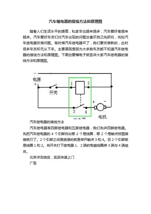
汽车继电器的接线方法汽车继电器有四脚继电器和五脚继电器,我们先讲四脚继电器。
先把汽车继电器的4个引脚找出哪2个是线圈,哪2个是触点按图接接就行了。
2个引脚之间是绝缘的就是常开触点3和4。
另2个引脚就是线圈1和2。
当开关打下继电器1、2端的电磁线圈將3端与4端結合。
北京点击抽奖,奖品快递上门广告汽车四脚继电器分85 / 86/ 87 /(30A/87A)的4条线。
85/86这两条是喇叭控制线,85接控制线的正极,86搭铁喇叭的另一个接线柱,不分正负极。
87接电瓶正极,30A/87A接需要控制的电器的正极线。
展开剩余74%汽车五脚继电器其中两脚是线圈电源,另三脚是常开、常闭点。
一般继电器上有触电示意图,也可用万用表检测出来。
一般来说,三支脚的那一边中间是输出触点的公共端子,另外两个引脚是线圈。
两只脚的一端是输出的常开和常闭触点,和公共端子通的是常开,和公共端子不通的常闭。
五脚可以同时断开原来的线路并接通其他线路。
根据各自需求,五脚能代替四脚使用。
汽车继电器原理图汽车继电器原理图是汽车继电器最基础的知识,要想玩转汽车继电器首先我们要知道它的原理。
起动机的工作原理,汽车起动机的控制装置包括电磁开关、起动汽车继电器和点火起动开关灯部件,其中电磁开关于起动机制作在一起。
电磁开关结构特点电磁开关主要由电磁铁机构和电动机开关两部分组成。
电磁铁机构由固定铁心、活动铁心、吸引线圈和保持线圈等组成。
固定铁心固定不动,活动铁心可以在铜套里做轴向移动。
活动铁心前端固定有推杆,推杆前端安装有开关触盘,活动铁心后段用调节螺钉和连接销与拨叉连接。
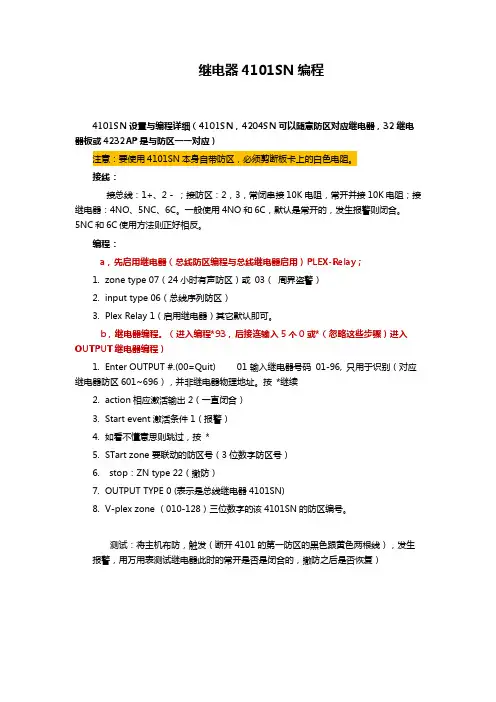
继电器4101SN编程4101SN设置与编程详细(4101SN,4204SN可以随意防区对应继电器,32继电器板或4232AP是与防区一一对应)注意:要使用4101SN本身自带防区,必须剪断板卡上的白色电阻。
接线:接总线:1+、2 - ;接防区:2,3,常闭串接10K电阻,常开并接10K电阻;接继电器:4NO、5NC、6C。
一般使用4NO和6C,默认是常开的,发生报警则闭合。
5NC和6C使用方法则正好相反。
编程:a,先启用继电器(总线防区编程与总线继电器启用)PLEX-Relay;1.zone type 07(24小时有声防区)或03(周界盗警)2.input type 06(总线序列防区)3.Plex Relay 1(启用继电器)其它默认即可。
b,继电器编程。
(进入编程*93,后接连输入5个0或*(忽略这些步骤)进入OUTPUT继电器编程)1.Enter OUTPUT #.(00=Quit) 01 输入继电器号码01-96, 只用于识别(对应继电器防区601~696),并非继电器物理地址。
按*继续2.action相应激活输出 2(一直闭合)3.Start event激活条件 1(报警)4.如看不懂意思则跳过,按*5.STart zone 要联动的防区号(3位数字防区号)6.stop:ZN type 22(撤防)7.OUTPUT TYPE 0 (表示是总线继电器4101SN)8.V-plex zone (010-128)三位数字的该4101SN的防区编号。
测试:将主机布防,触发(断开4101的第一防区的黑色跟黄色两根线),发生报警,用万用表测试继电器此时的常开是否是闭合的,撤防之后是否恢复)。


带 2/3 开关点和 IO-Link(最多 16 个开关点)且具有诊断功能的 MPS-G磁性气缸传感器所说明的产品MPS-G制造商SICK AGErwin-Sick-Str.179183 Waldkirch, Germany德国法律信息本文档受版权保护。
其中涉及到的一切权利归西克公司所有。
只允许在版权法的范围内复制本文档的全部或部分内容。
未经西克公司的明确书面许可,不允许对文档进行修改、删减或翻译。
本文档所提及的商标为其各自所有者的资产。
© 西克公司版权所有。
原始文档本文档为西克股份公司的原始文档。
2操作指南 | 带 2/3 开关点和 IO-Link(最多 16 个开关点)且具有诊断功能的 MPS-G8025951.1GWA/2022-08-15 | SICK如有更改,恕不另行通知内容内容1关于本文档的 (5)1.1更多信息 (5)1.2符号和文档约定 (5)2安全信息 (6)2.1规定用途 (6)2.2违规使用 (6)2.3责任范围 (6)2.4对专业人员和操作人员的要求 (6)2.5危险提示与作业安全 (7)2.6关于 UL 认证的提示 (7)3产品说明 (8)3.1产品识别 (8)3.1.1设备视图 (8)3.2产品特征 (8)3.2.1产品特点 (8)3.3作业方法 (9)3.3.1工作原理 (9)3.3.2识别范围 (9)3.3.3位置输出 (10)3.3.4在手动示教最多 3 个开关点之后的开关性能 (10)3.3.5动态示教 2 个开关点之后的开关性能 (11)3.3.6动态示教 3 个开关点之后的开关性能 (13)4运输和仓储 (18)4.1运输 (18)4.2运输检查 (18)4.3储存环境 (18)5装配 (19)5.1安装要求 (19)5.2可选的配件 (19)5.3固定/安装 (19)6电气安装 (20)6.1安全性 (20)6.1.1关于电气安装的提示 (20)6.1.2接线提示 (20)6.2接口 (21)6.2.1引脚分配/接口示意图 + 芯线颜色 (21)6.3连接工作电压 (22)7调试 (23)7.1调试步骤概览 (23)8025951.1GWA/2022-08-15 | SICK操作指南 | 带 2/3 开关点和 IO-Link(最多 16 个开关点)且具有诊断功能的 MPS-G3如有更改,恕不另行通知内容7.2驱动装置的定位 (23)7.3首次运行传感器 (23)8操作 (24)8.1有关操作的一般提示 (24)8.2操作及显示元件 (24)8.2.1操作元件 (24)8.2.2显示元件 (25)8.3示教模式 (25)8.3.1动态示教 (26)8.3.2手动示教 (28)8.4诊断功能 (32)8.4.1振动分析 (33)8.4.2位置监控 (35)8.4.3温度测量 (37)8.4.4最大加速度 (37)9过程数据结构 (38)10故障排除 (39)11维护 (40)12停机 (41)12.1备用设备 (41)12.2拆卸和废弃处理 (41)12.3寄回设备 (41)13技术数据 (42)13.1尺寸图 (43)14术语表 (45)15附件 (48)15.1示教程序概览 (48)15.2合规性和证书 (48)4操作指南 | 带 2/3 开关点和 IO-Link(最多 16 个开关点)且具有诊断功能的 MPS-G8025951.1GWA/2022-08-15 | SICK如有更改,恕不另行通知1关于本文档的1.1更多信息查看产品页面更多信息,请访问 SICK Product ID:/{P/N}。

Extend Pressure Measurement into High Temperature ApplicationsIntroductionMeasurement of pressure plays a central role in many areas of a plant, in the manufacturing industry, in machine tooling, in process engineering, and in the manufacture and processing of food andbeverages. Pressure measurement in industrial applications typically occurs with the help of pressure transmitters and switches. Pressure transmitters deliver a continuous current or voltage signal proportional to the pressure applied. Pressure switches are used to monitor pressure. Electronic pressure switches are characterized by their digital switching outputs, which are activated or deactivated when the defined, programmable threshold levels have been reached.Monitoring, measuring, and controlling pressure can be tricky if the process temperature exceeds the limits of the pressure instrumentation, such as pressure transmitters and switches. It is possible to obtain an accurate pressure measurement using standard pressure transmitters in these high temperature applications. The trick is to ensure that the process is cooled before reaching the pressure measuring device.There are generally two different methods used to protect the pressure transmitter and/or the pressure switch from high temperatures. These two proven methods are done through the use of coolingelements and standoff piping. Provided below are guidelines on how to protect the pressure devices from extreme temperatures using cooling elements and standoff piping.Cooling ElementsA cooling element is an accessory that puts some distance between the transmitter and the heat of the process. There are often times “fins” that allow for air circulation for betterheat dissipation. Cooling elements are designed to cool the process to a temperature that is within the specifications of the pressure transmitter.Cooling elements are a great way to protect the transmitter from high temperature processes. Cooling elements act as a heat sink, which cools the process before it reaches the transmitter.Cooling elements can extend the maximum process temperature of pressure transmitters from 185 °F (85 °C) up to 392 °F (200 °C).Figure 1: Cooling element.Figure 2: Cooling element attached to PBS Pressure Transmitter, Switch, and Display.Cooling elements from SICK provide heat protection as shown in the tables below. For the PBS electronic pressure switch, pressure transmitter and display; cooling elements can protect within the following guidelines:Chart 1: Temperature range of PBS pressure transmitter, switch, and display when installed with a cooling element (°F).PBS maximum process temperature when installed without a cooling element is 185 °F.For the PBS electronic pressure switch, pressure transmitter and display; cooling elements can protect within the following guidelines:Chart 2: Temperature range of PBS pressure transmitter, switch, and display when installed with a cooling element (°C).PBS maximum process temperature when installed without a cooling element is 85 °C.Chart 3: Temperature range of PFT pressure transmitter when installed with a cooling element (°F).PFT maximum process temperature when installed without a cooling element is 212 °F.For the PFT pressure transmitter; cooling elements can protect within the following guidelines:Chart 4:Temperature range of PFT pressure transmitter when installed with a cooling element (°C).PFT maximum process temperature when installed without a cooling element is 100 °C.Chart 5: Temperature range of PBT pressure transmitter when installed with a cooling element (°F).PBT maximum process temperature when installed without a cooling element is 176 °F.For the PBT pressure transmitter; cooling elements can protect within the following guidelines:Chart 6: Temperature range of PBT pressure transmitter when installed with a cooling element (°C).PBT maximum process temperature when installed without a cooling element is 80 °C.If cooling elements do not provide enough cooling to meet the application, standoff piping / impulse lines may be used.Standoff PipingUsing standoff piping (otherwise known as impulse lines) cools the process before it comes in contact with the pressure transmitter. Standoff piping may also allow the user to relocate the transmitter to a more convenient location for maintenance.Impulse line lengths are calculated using a general rule of thumb. For every 100 °F that the temperature needs to drop, users need to have 1 foot of impulse lines. For instance the maximum process temperature specification of the PBS pressure transmitter, switch, and display is 185 ° F (85 °C). If the process temperature is 585 °F, the process would have to be cooled 400 °F to be within the transmitter specification (585 - 185 = 400). Where 585 is the process temperature in °F, 180 is the maximum process temperature of the PBS, and 400 is the decrease in the temperate required for the transmitter. Dropping the process temperature by 400 °F is easily done using a minimum of 4 feet of impulse lines. This is a general rule of thumb, assuming a 68 °F (20 °C) ambient temperature. For higher ambient temperatures, longer impulse lines are required. For lower ambient temperatures, shorter impulse lines are required. Also, most users add a little more pipe length for added peace of mind.If the impulse lines are too long, other problems may present themselves:•Damping of the pressure signal•Blockage of the pressure signal•Leakage at couplingsTherefore, a balance between just long enough and too long must be achieved. Piping diameters should be as follows:Type of measured fluidImpulse Line Length0-52.5 ft (0-16 m) 52.5-148 ft (16-45 m) 148-295 ft (45-90 m)Water/steam and dryair/gas0.27-0.35 in (7-9 mm) 0.4 in (10 mm) 0.51 in (13 mm) Wet air/wet gas 0.51 in (13 mm) 0.51 in (13 mm) 0.51 in (13 mm) Oils of low mediumviscosity0.51 in (13 mm) 0.75 in (19 mm) 0.98 in (25 mm) Very dirty fluids 0.98 in (25 mm) 0.98 in (25 mm) 1.50 in (38 mm)Table 1: Impulse line diameters from ISO2186:1973Type of metered fluid Impulse Line Length0-52.5 ft (0-16 m) 52.5-148 ft (16-45 m) Water/steam and dry air/gas0.27-0.35 in (7-9 mm) 0.4 in (10 mm) Wet air/wet gas 0.51 in (13 mm) 0.51 in (13 mm) Oils of low medium viscosity0.51 in (13 mm) 0.75 in (19 mm) Very dirty fluids0.98 in (25 mm)0.98 in (25 mm)Table 2: Impulse line diameters from ISO/CD 2186:2004Gas ApplicationsMount hardware upward to allow moisture to drain out and not fill the impulse piping:• Slope impulse piping at least one inch per foot(8 centimeters per meter) downward from the transmitter toward the process connection.Liquid ApplicationsMount hardware downward to allow the escape of trapped vapor in the impulse piping:• Slope impulse piping at least one inch per foot(8 centimeters per meter) upward from the transmitter toward the process connection. • Vent all gas from the liquid piping legs.• Prevent sediment deposits in the impulse piping.ConclusionThere are generally two different methods used to protect the pressure transmitter and/or the pressure switch from high temperatures. These two proven methods are cooling elements and standoff piping. Some of the time a combination of both methods is used to give the engineer added peace of mind. By using either method, a standard pressure transmitter and/or pressure switch may be used in high temperature applications.Figure 4: Mounting hardware for liquid applications.Figure 3: Mounting hardware for gas applications.。

西克SICK传感器不同的型号使用方法解析对SICK传感器本身的质量和性能有更高的要求,特别是作为用于精确测试的SICK传感器。
对于那些使用位移传感器的人来说,有必要了解位移传感器的应用方法和注意事项。
在了解SICK传感器的应用方法之前,小编首先简要介绍了SICK传感器(线性位移传感器)的主要特征参数。
SICK传感器的主要特性参数(位移传感器原理)标称电阻:电位器上指示的电阻值。
允许误差:标称电阻与实际电阻之比与标称电阻之比是电阻偏差,表示电位计的精度。
允许误差通常在±20%内得到满足,因为通常的位移传感器是通过分压施加的。
特定电阻的大小对传感器的数据采集没有影响。
线性精度:线性误差。
参数越小越好。
寿命:导电塑料位移传感器超过200万次。
重复性:参数越小越好。
分辨率:位移传感器可以反映的Zui的小位移值。
参数越小越好。
导电塑料位移传感器的分辨率极小。
如何使用SICK传感器:通常,通过使用其优异的平滑度,向SICK传感器施加电压以检测输出电压(输出电阻改变输出电压)。
小编收集并组织了线性SICK传感器和磁致伸缩位移传感器作为例子来分析位移传感器的使用。
(1)使用SICK传感器:由Minor MINOR生产的精密线性位移传感器配备了一个长连续传导轨迹型压力传感器。
它适用于控制和测量应用中的绝对位移传感,线性精度为0.05%。
它具有运动快,寿命长的特点,满足龙门精密液压机的控制要求。
根据实际要求,Kl下滑式和KTC拉杆式线性位移传感器分别安装在液压机的主缸和液压垫上。
在半自动工作过程中,液压机的主缸和液压垫分别驱动两个线性SICK传感器移动,并将收集值的两个模拟值输入到FX2N-8AD。
FX2N-8AD输入模拟输入值。
电压输入),转换为数字值并传送到PLC主机。
sick安全继电器工作原理SICK安全继电器是一种用于机器安全控制的设备,它能够在机器运行过程中监测环境参数并及时采取控制措施,以确保工作场所的安全。
本文将介绍SICK安全继电器的工作原理及其在工业领域中的应用。
我们来了解一下SICK安全继电器的基本构成。
它由多个传感器、电路板和继电器组成。
传感器用于检测环境参数,如温度、压力、光照等。
电路板则负责对传感器采集到的信号进行处理,并根据需要发送控制信号给继电器。
继电器是安全继电器的核心部件,它能够根据控制信号的输入和输出状态,实现对机器的控制。
SICK安全继电器的工作原理可以简单概括为以下几个步骤:1. 传感器采集环境参数:SICK安全继电器通过多个传感器采集环境参数,例如温度、压力、光照等。
这些传感器能够将环境参数转化为电信号,并将其发送给电路板。
2. 电路板处理信号:电路板接收到传感器发送的信号后,会对其进行处理。
处理的方式可以是放大、滤波、幅度调节等。
通过对信号的处理,电路板能够将其转化为继电器能够识别和使用的信号。
3. 控制信号输入:经过处理的信号将被发送给继电器。
继电器会根据信号的输入状态来判断是否需要对机器进行控制。
例如,当温度过高时,继电器会接收到一个控制信号,根据该信号判断是否需要停止机器的运行。
4. 控制信号输出:如果继电器判断需要对机器进行控制,则会输出一个控制信号。
这个控制信号可以是一个开关信号,用于打开或关闭机器的电源;也可以是一个调节信号,用于调节机器的运行状态。
继电器通过控制信号的输出来实现对机器的控制。
SICK安全继电器在工业领域中有着广泛的应用。
它可以用于各种机器的安全控制,例如工业机器人、自动化生产线、物流设备等。
通过安装SICK安全继电器,可以有效地保护工作场所的安全,防止事故的发生。
以工业机器人为例,SICK安全继电器可以用于监测机器人的运行状态和周围环境。
当机器人发生异常情况时,例如温度过高、光照不足或碰撞等,继电器会及时发送控制信号,使机器人停止运行或调整运行状态,以避免事故的发生。
Flexiclassic UE410 操作手册目录目录 (2)1.UE410-MU系列面板介绍及各拨码开关的定义 (3)2.UE410-MU功能部分接线 (11)3.UE410-MU参数设置 (15)4.UE410-MU示范接线图 (16)1. UE410-MU 系列系列面板介绍及面板介绍及面板介绍及各拨码开关的定义各拨码开关的定义UE410-MU 是Flexiclassic 的主模块,UE410-XU 是Flexiclassic 带输入输出的扩展模块, UE410-8DI 是Flexiclassic 只带输入的扩展模块。
首先UE410-MU 主模块的面板介绍UE410-MU 主模块面板上各显示灯的介绍 显示 含义PWR(绿色)24V 电源指示灯Q1/Q2, Q3/Q4 (绿色) 安全输出的状态(高电平) Q3/Q4 (绿色闪烁) Q3/Q4输出高电平延迟时间时闪烁 ERR (红色或者闪烁) 此模块出错EN, S1 到S3 (绿色) 此接点有24V 电 I1-I4(绿色)此输入有信号(高电平)I1,I2同时闪烁I1,I2之间互相短路I3,I4同时闪烁I3,I4之间互相短路I1,I2顺序交叉闪烁I1,I2输入出错I3,I4顺序交叉闪烁I3,I4输入出错I1-I4顺序闪烁同步时间出错,或者是相应的输入得到了不希望的输入S1 到S3 顺序闪烁没有得到期望的EDM 与/或复位信号UE410-MU主模块面板上开关按钮的介绍开关/按钮功能编程功能选择选择不同的接线对应不同的功能,详见后续介绍延迟时间选择设置不同的延迟时间ENTER键确定参数设置的按钮开关UE410-MU主模块面板上输入输出介绍I1/I2 逻辑A的输入I3/I4 逻辑B的输入EN 使能输入端,激活使能控制(例如EDM和手动复位、自动复位)S1,S2,S3 手动复位按钮,EDM,测试等的输入端,A1,A2 电源端(A1--24V,A2—0V)X1,X2 测试输入端,用于测试I1,I2或I3,I4的交叉检测Q1–Q4 被监控的晶体管输出(OSSD)Q3 模式3下作为Muting 灯显示另外还有UE410-MX扩展模块,与主模块UE410-MU功能和接线都一样,只是没有功能设置ENTER按钮。
SICK UE410连接指南1.UE410程序设定步骤
•旋转编程模式旋钮,选择需要的功能模式
•使用螺丝刀按住teach按钮
•UE410上电启动,在1.5S--2S左右,松开螺丝刀•设备指示灯OK,设备正常运行
2.UE410连接样例
•UE410连接一台ESPE(光幕/激光扫描仪)
•UE410连接两台ESPE(光幕/激光扫描仪)
•UE410连接一台ESPE+一个急停按钮/门开关
•UE410连接两个急停按钮/门开关
(1) UE410连接一台ESPE(光幕/激光扫描仪)
模式选择7
(2) UE410连接两台ESPE(光幕/激光扫描仪),两台设备没有联动逻辑关系模式选择8
(3) UE410连接两台ESPE,两台设备有联动逻辑关系
模式选择7
(4) UE410连接一台ESPE+一个急停按钮/门开关
模式选择为7(急停按钮/门开关没有测试脉冲,有手动复位)
模式选择为9(急停按钮/门开关带有测试脉冲)
(5) UE410连接两个急停按钮/门开关
模式选择为7(急停/门开关不带测试脉冲)
模式选择为9(注意两个急停不能都带测试脉冲,只能一个带测试脉冲)。