Agilent N4010A蓝牙测试的参数介绍
- 格式:doc
- 大小:16.00 KB
- 文档页数:2
文件名称 蓝牙测试仪操作指导书文件编号 版本 V1.0 正气 进取 专业发布日期 主控部门 综合测试部意见签名/日期拟制: 综合测试部 同意 袁丕超 2007-06-05 审核:审核: 质量管理部审核: 质量策划部审核: 管理者代表文件说明(部门在此文件中的主要职责)研发体系硬件部、测试部负责实施,综合测试部负责此规范的维护。
版本号 修改时间 修改人 修改原因 修改主要内容V1.0 2007-06-05 袁丕超创建1、目的: 保证龙旗控股有限公司设计、委托制造的手机及相关产品的蓝牙性能测试所使用的设备进行规范化操作,特制定此文件;2、使用范围: 本文件适用于龙旗控股有限公司质量中心-综合测试部硬件实验室的设备,使用于公司所有带蓝牙(Class 2)功能的项目。
由蓝牙测试人员责实施;3、定义:无4、职责: 1、综合测试部硬件实验室工程师负责设备维护,保证设备正常运行及清洁工作。
2、研发体系硬件部、测试部严格按照此指导书执行;5、操作步骤:5.1蓝牙测试仪5.1.1 型号:N4010A(仪器N4010A目前选项为101:即为蓝牙测试模块,本指导书只介绍该模块5.1.1.1 仪器简要说明:1、为蓝牙主设备使用,进行查询,以测试模式或者普通模式建立寻呼连接2、RF测试规范1.2进行测量3、内置排序器,可简单的创建与编辑测试计划4、提供SIG标准设置默认所有的测试,用户可改变设置,满足特定的测试要求5.1.1.2 蓝牙测试仪N4010A一般技术指标:频率参考:频率: 10 MHz精度: 0.5 ppm2.5 ppm, 0 - 550C10 MHz输入: BNC (f), 50欧姆10 MHz输出: BNC (f), 50欧姆功率要求:电压 100-240V AC频率: 50到60HZ功率: 最大到150VA环境工作温度:0到55℃储存温度:-20到+70℃工作湿度:40-95%的相对湿度海拔高度:3000米(9840英尺)EMI兼容能力:Meets EN55011: 1991 (Group 1, Class A), andEN50082- 1:1992.5.1.2 操作步骤:5.1.2.1蓝牙射频测试项目、参数配置及按键与接口介绍:(测试八个蓝牙射频测试项目)5.1.2.1.1测试项目与参数配置Transmitter(发射测试)Output Power(输出功率):Modulation Characteristics(调制能力):Initial Carrier Frequency Tolerance(ICFT) 载波的初始频率误差: Carrier Frequency Drift(载波频率漂移)接受测试:1.最大输入电平(Maximum input Level)2.灵敏度测试(单时隙和多时隙):Single-slot SensitivityMulti-Slot Sensitivity测试仪与EUT之间的蓝牙链路的参数进行配置:EUT测试方式(是环回还是发送方式,跳频(Hopping)状态(ON或者OFF),分组的净菏(即有效载荷)类型:PRBS9、BS00、BSFF、BS0F、BS55;分组类型:单时隙分组(如:DH1、DH3、DH5、HV3),多时隙分组(DH135)测量带宽:5.1.2.1.2按键与接口介绍前面板Preset Key:恢复到出厂设置Help/Local Key – 帮助菜单System Key – 系统菜单用与设置系统的一些功能:通讯配置(如CPIB地址、IP地址、默认网关,仪器校准,、硬件信息、错误显示)等。

蓝牙测试仪N4010A操作指导1.准备工作:-将N4010A测试仪连接到计算机,并确保驱动程序已正确安装。
-打开测试仪软件并登录。
2.连接设备:-确保要测试的蓝牙设备已打开并处于可连接状态。
-在测试仪软件中,选择"连接设备"选项,并可用设备列表。
-选择要连接的设备,并点击"连接"按钮。
3.配置测试参数:-在测试仪软件中,选择"配置测试参数"选项。
-根据需要选择要测试的蓝牙规范和测试模式。
-设置其他相关的测试参数,如频率范围和功率等级。
4.运行测试:-在测试仪软件中,选择"运行测试"选项。
-确保测试设备和被测设备之间的连接稳定。
-点击"开始测试"按钮,测试仪将开始执行选择的测试。
5.查看结果:-测试仪将在测试进行期间显示实时结果。
-在测试完成后,可以查看详细的测试报告和结果数据。
-结果数据可以用于评估设备的蓝牙性能,并进行进一步的优化和调整。
6.进阶功能:-N4010A测试仪还提供了一些进阶功能,如信号发生器、频谱分析等。
-这些功能可以用于进行更深入的蓝牙性能评估和故障排查。
需要注意的是,N4010A测试仪的具体操作流程可能会根据软件版本和配置的不同而有所不同。
建议在操作之前仔细阅读测试仪的用户手册,了解具体的操作指导。
总结:通过上述操作指导,您可以正确地操作蓝牙测试仪N4010A,并进行各种蓝牙设备的测试。
这将有助于提高设备的蓝牙性能,并确保其符合相关的蓝牙标准和指南。

User’s and Programmer’s ReferenceVolume 2One-Button Power Measurements PSA and ESA Series Spectrum Analyzers Refer to Volume 1 for core spectrum analyzer information.This manual provides documentation for the following instruments:Agilent Technologies PSA SeriesE4443A (3 Hz - 6.7 GHz)E4445A (3 Hz - 13.2 GHz)E4440A (3 Hz - 26.5 GHz)E4447A (3 Hz - 42.98 GHz)E4446A (3 Hz - 44.0 GHz)E4448A (3 Hz - 50.0 GHz)Agilent Technologies ESA-E SeriesE4402B (9kHz - 3.0GHz)E4404B (9kHz - 6.7GHz)E4405B (9kHz - 13.2GHz)E4407B (9kHz - 26.5GHz)Agilent Technologies ESA-L SeriesE4411B (9kHz- 1.5GHz)E4403B (9kHz - 3.0GHz)E4408B (9kHz - 26.5GHz)Manufacturing Part Number: E4440-90618Supersedes: E4440-90346Printed in USAMarch 2014© Copyright 1999-2014 Agilent Technologies, Inc..Legal InformationThe information contained in this document is subject to change without notice.Agilent Technologies makes no warranty of any kind with regard to this material, including but not limited to, the implied warranties of merchantability and fitness for a particular purpose. Agilent Technologies shall not be liable for errors contained herein or for incidental or consequential damages in connection with the furnishing, performance, or use of this material.Where to Find the Latest InformationDocumentation is updated periodically.•For the latest information about Agilent Technologies PSA Spectrum Analyzers, including firmware upgrades and application information, please visit the following Internet URL:/find/psa•For the latest information about Agilent Technologies ESA Spectrum Analyzers, including firmware upgrades and application information, please visit the following Internet URL:/find/esa•To receive the latest updates by email, subscribe to Agilent Email Updates:/find/emailupdates•Information on preventing spectrum analyzer damage can be found at:/find/tips21. Using This DocumentAbout the User’s and Programmer’s Information. . . . . . . . . . . . . . . . . . . . . . . . . . . . . . . . . . . . . . . . . . . . . 26 What is in This Book. . . . . . . . . . . . . . . . . . . . . . . . . . . . . . . . . . . . . . . . . . . . . . . . . . . . . . . . . . . . . . . . . 26 Terms Used in This Book . . . . . . . . . . . . . . . . . . . . . . . . . . . . . . . . . . . . . . . . . . . . . . . . . . . . . . . . . . . . . 27 2. One-Button Measurement FunctionsOne - Button Measurement Functions . . . . . . . . . . . . . . . . . . . . . . . . . . . . . . . . . . . . . . . . . . . . . . . . . . . . . 30 Mode Setup (Spectrum Analysis Mode) . . . . . . . . . . . . . . . . . . . . . . . . . . . . . . . . . . . . . . . . . . . . . . . . . . . 33 Radio Std. . . . . . . . . . . . . . . . . . . . . . . . . . . . . . . . . . . . . . . . . . . . . . . . . . . . . . . . . . . . . . . . . . . . . . . . . . 33 Radio Std Setup. . . . . . . . . . . . . . . . . . . . . . . . . . . . . . . . . . . . . . . . . . . . . . . . . . . . . . . . . . . . . . . . . . . . . 45 Retain Params . . . . . . . . . . . . . . . . . . . . . . . . . . . . . . . . . . . . . . . . . . . . . . . . . . . . . . . . . . . . . . . . . . . . . . 47 Enable All Measurements. . . . . . . . . . . . . . . . . . . . . . . . . . . . . . . . . . . . . . . . . . . . . . . . . . . . . . . . . . . . . 47 Autorange of Power Setting (Remote command only). . . . . . . . . . . . . . . . . . . . . . . . . . . . . . . . . . . . . . . 48 MEASURE (Spectrum Analysis Mode) . . . . . . . . . . . . . . . . . . . . . . . . . . . . . . . . . . . . . . . . . . . . . . . . . . . 49 Command Interactions: MEASure, CONFigure, FETCh, INITiate and READ. . . . . . . . . . . . . . . . . . . . 50 Current Measurement Query (Remote Command Only) . . . . . . . . . . . . . . . . . . . . . . . . . . . . . . . . . . . . . 53 Test Current Results Against all Limits (Remote Command Only) . . . . . . . . . . . . . . . . . . . . . . . . . . . . . 53 Meas Off . . . . . . . . . . . . . . . . . . . . . . . . . . . . . . . . . . . . . . . . . . . . . . . . . . . . . . . . . . . . . . . . . . . . . . . . . . 54 Channel Power . . . . . . . . . . . . . . . . . . . . . . . . . . . . . . . . . . . . . . . . . . . . . . . . . . . . . . . . . . . . . . . . . . . . . 54 Occupied BW . . . . . . . . . . . . . . . . . . . . . . . . . . . . . . . . . . . . . . . . . . . . . . . . . . . . . . . . . . . . . . . . . . . . . . 57 Adjacent Channel Power—ACP. . . . . . . . . . . . . . . . . . . . . . . . . . . . . . . . . . . . . . . . . . . . . . . . . . . . . . . . 58 Multi-Carrier Power . . . . . . . . . . . . . . . . . . . . . . . . . . . . . . . . . . . . . . . . . . . . . . . . . . . . . . . . . . . . . . . . . 62 Power Stat CCDF . . . . . . . . . . . . . . . . . . . . . . . . . . . . . . . . . . . . . . . . . . . . . . . . . . . . . . . . . . . . . . . . . . . 64 Harmonic Distortion . . . . . . . . . . . . . . . . . . . . . . . . . . . . . . . . . . . . . . . . . . . . . . . . . . . . . . . . . . . . . . . . . 67 Burst Power . . . . . . . . . . . . . . . . . . . . . . . . . . . . . . . . . . . . . . . . . . . . . . . . . . . . . . . . . . . . . . . . . . . . . . . 70 Intermod (TOI) . . . . . . . . . . . . . . . . . . . . . . . . . . . . . . . . . . . . . . . . . . . . . . . . . . . . . . . . . . . . . . . . . . . . . 73 Spurious Emissions . . . . . . . . . . . . . . . . . . . . . . . . . . . . . . . . . . . . . . . . . . . . . . . . . . . . . . . . . . . . . . . . . 74 Spectrum Emission Mask . . . . . . . . . . . . . . . . . . . . . . . . . . . . . . . . . . . . . . . . . . . . . . . . . . . . . . . . . . . . . 75 Meas Setup (Adjacent Channel Power—ACP) . . . . . . . . . . . . . . . . . . . . . . . . . . . . . . . . . . . . . . . . . . . . . . 83 Avg Number . . . . . . . . . . . . . . . . . . . . . . . . . . . . . . . . . . . . . . . . . . . . . . . . . . . . . . . . . . . . . . . . . . . . . . . 83 Avg Mode . . . . . . . . . . . . . . . . . . . . . . . . . . . . . . . . . . . . . . . . . . . . . . . . . . . . . . . . . . . . . . . . . . . . . . . . . 84 Chan Integ BW . . . . . . . . . . . . . . . . . . . . . . . . . . . . . . . . . . . . . . . . . . . . . . . . . . . . . . . . . . . . . . . . . . . . . 84 Offset/Limits. . . . . . . . . . . . . . . . . . . . . . . . . . . . . . . . . . . . . . . . . . . . . . . . . . . . . . . . . . . . . . . . . . . . . . . 85 Meas Type . . . . . . . . . . . . . . . . . . . . . . . . . . . . . . . . . . . . . . . . . . . . . . . . . . . . . . . . . . . . . . . . . . . . . . . . 89 Optimize Ref Level . . . . . . . . . . . . . . . . . . . . . . . . . . . . . . . . . . . . . . . . . . . . . . . . . . . . . . . . . . . . . . . . . 90 Method . . . . . . . . . . . . . . . . . . . . . . . . . . . . . . . . . . . . . . . . . . . . . . . . . . . . . . . . . . . . . . . . . . . . . . . . . . . 91 Total Pwr Ref . . . . . . . . . . . . . . . . . . . . . . . . . . . . . . . . . . . . . . . . . . . . . . . . . . . . . . . . . . . . . . . . . . . . . . 94 PSD Ref. . . . . . . . . . . . . . . . . . . . . . . . . . . . . . . . . . . . . . . . . . . . . . . . . . . . . . . . . . . . . . . . . . . . . . . . . . . 95 Limit Test . . . . . . . . . . . . . . . . . . . . . . . . . . . . . . . . . . . . . . . . . . . . . . . . . . . . . . . . . . . . . . . . . . . . . . . . . 96 RRC Filter . . . . . . . . . . . . . . . . . . . . . . . . . . . . . . . . . . . . . . . . . . . . . . . . . . . . . . . . . . . . . . . . . . . . . . . . 96 Filter Alpha . . . . . . . . . . . . . . . . . . . . . . . . . . . . . . . . . . . . . . . . . . . . . . . . . . . . . . . . . . . . . . . . . . . . . . . 97 Noise Correction . . . . . . . . . . . . . . . . . . . . . . . . . . . . . . . . . . . . . . . . . . . . . . . . . . . . . . . . . . . . . . . . . . . 97 Trace/View (ACP Measurement) . . . . . . . . . . . . . . . . . . . . . . . . . . . . . . . . . . . . . . . . . . . . . . . . . . . . . . . . . 99 Spectrum . . . . . . . . . . . . . . . . . . . . . . . . . . . . . . . . . . . . . . . . . . . . . . . . . . . . . . . . . . . . . . . . . . . . . . . . . . 99 Bar Graph . . . . . . . . . . . . . . . . . . . . . . . . . . . . . . . . . . . . . . . . . . . . . . . . . . . . . . . . . . . . . . . . . . . . . . . . . 99 Combined . . . . . . . . . . . . . . . . . . . . . . . . . . . . . . . . . . . . . . . . . . . . . . . . . . . . . . . . . . . . . . . . . . . . . . . . 100 Combined View Units. . . . . . . . . . . . . . . . . . . . . . . . . . . . . . . . . . . . . . . . . . . . . . . . . . . . . . . . . . . . . . . 100 Trace . . . . . . . . . . . . . . . . . . . . . . . . . . . . . . . . . . . . . . . . . . . . . . . . . . . . . . . . . . . . . . . . . . . . . . . . . . . . 100 Meas Setup (Burst Power) . . . . . . . . . . . . . . . . . . . . . . . . . . . . . . . . . . . . . . . . . . . . . . . . . . . . . . . . . . . . . 1013Avg Number . . . . . . . . . . . . . . . . . . . . . . . . . . . . . . . . . . . . . . . . . . . . . . . . . . . . . . . . . . . . . . . . . . . . . . 101 Avg Mode . . . . . . . . . . . . . . . . . . . . . . . . . . . . . . . . . . . . . . . . . . . . . . . . . . . . . . . . . . . . . . . . . . . . . . . . 102 Average Type . . . . . . . . . . . . . . . . . . . . . . . . . . . . . . . . . . . . . . . . . . . . . . . . . . . . . . . . . . . . . . . . . . . . . 103 Threshold Lvl . . . . . . . . . . . . . . . . . . . . . . . . . . . . . . . . . . . . . . . . . . . . . . . . . . . . . . . . . . . . . . . . . . . . . 103 Meas Method . . . . . . . . . . . . . . . . . . . . . . . . . . . . . . . . . . . . . . . . . . . . . . . . . . . . . . . . . . . . . . . . . . . . . 104 Burst Width. . . . . . . . . . . . . . . . . . . . . . . . . . . . . . . . . . . . . . . . . . . . . . . . . . . . . . . . . . . . . . . . . . . . . . . 104 Optimize Ref Level. . . . . . . . . . . . . . . . . . . . . . . . . . . . . . . . . . . . . . . . . . . . . . . . . . . . . . . . . . . . . . . . . 106 Trace/View (Burst Power) . . . . . . . . . . . . . . . . . . . . . . . . . . . . . . . . . . . . . . . . . . . . . . . . . . . . . . . . . . . . . 107 RF Envelope. . . . . . . . . . . . . . . . . . . . . . . . . . . . . . . . . . . . . . . . . . . . . . . . . . . . . . . . . . . . . . . . . . . . . . 107 Combined . . . . . . . . . . . . . . . . . . . . . . . . . . . . . . . . . . . . . . . . . . . . . . . . . . . . . . . . . . . . . . . . . . . . . . . . 108 Trace . . . . . . . . . . . . . . . . . . . . . . . . . . . . . . . . . . . . . . . . . . . . . . . . . . . . . . . . . . . . . . . . . . . . . . . . . . . . 108 Meas Setup (Complementary Cumulative Distribution Function—CCDF) . . . . . . . . . . . . . . . . . . . . . . . 109 Meas BW . . . . . . . . . . . . . . . . . . . . . . . . . . . . . . . . . . . . . . . . . . . . . . . . . . . . . . . . . . . . . . . . . . . . . . . . 109 Counts . . . . . . . . . . . . . . . . . . . . . . . . . . . . . . . . . . . . . . . . . . . . . . . . . . . . . . . . . . . . . . . . . . . . . . . . . . 110 Meas Interval . . . . . . . . . . . . . . . . . . . . . . . . . . . . . . . . . . . . . . . . . . . . . . . . . . . . . . . . . . . . . . . . . . . . . 111 Optimize Ref Level . . . . . . . . . . . . . . . . . . . . . . . . . . . . . . . . . . . . . . . . . . . . . . . . . . . . . . . . . . . . . . . . 112 Display (Complementary Cumulative Distribution Function—CCDF). . . . . . . . . . . . . . . . . . . . . . . . . . . 113 Full Screen . . . . . . . . . . . . . . . . . . . . . . . . . . . . . . . . . . . . . . . . . . . . . . . . . . . . . . . . . . . . . . . . . . . . . . . 113 Store Ref Trace. . . . . . . . . . . . . . . . . . . . . . . . . . . . . . . . . . . . . . . . . . . . . . . . . . . . . . . . . . . . . . . . . . . . 113 Ref Trace. . . . . . . . . . . . . . . . . . . . . . . . . . . . . . . . . . . . . . . . . . . . . . . . . . . . . . . . . . . . . . . . . . . . . . . . . 113 Gaussian Trace . . . . . . . . . . . . . . . . . . . . . . . . . . . . . . . . . . . . . . . . . . . . . . . . . . . . . . . . . . . . . . . . . . . . 114 Preferences . . . . . . . . . . . . . . . . . . . . . . . . . . . . . . . . . . . . . . . . . . . . . . . . . . . . . . . . . . . . . . . . . . . . . . . 114 Marker (Complementary Cumulative Distribution Function—CCDF) . . . . . . . . . . . . . . . . . . . . . . . . . . 115 Select Marker . . . . . . . . . . . . . . . . . . . . . . . . . . . . . . . . . . . . . . . . . . . . . . . . . . . . . . . . . . . . . . . . . . . . . 116 Normal . . . . . . . . . . . . . . . . . . . . . . . . . . . . . . . . . . . . . . . . . . . . . . . . . . . . . . . . . . . . . . . . . . . . . . . . . . 116 Delta . . . . . . . . . . . . . . . . . . . . . . . . . . . . . . . . . . . . . . . . . . . . . . . . . . . . . . . . . . . . . . . . . . . . . . . . . . . . 117 Off. . . . . . . . . . . . . . . . . . . . . . . . . . . . . . . . . . . . . . . . . . . . . . . . . . . . . . . . . . . . . . . . . . . . . . . . . . . . . . 117 Marker Trace . . . . . . . . . . . . . . . . . . . . . . . . . . . . . . . . . . . . . . . . . . . . . . . . . . . . . . . . . . . . . . . . . . . . . 118 Marker All Off . . . . . . . . . . . . . . . . . . . . . . . . . . . . . . . . . . . . . . . . . . . . . . . . . . . . . . . . . . . . . . . . . . . . 118 Marker X Position (Remote Command Only) . . . . . . . . . . . . . . . . . . . . . . . . . . . . . . . . . . . . . . . . . . . . 119 Marker Y Position (Remote Command Only) . . . . . . . . . . . . . . . . . . . . . . . . . . . . . . . . . . . . . . . . . . . . 120 Marker Maximum and Minimum (Remote Command Only) . . . . . . . . . . . . . . . . . . . . . . . . . . . . . . . . 120 SPAN X Scale (Complementary Cumulative Distribution Function—CCDF) . . . . . . . . . . . . . . . . . . . . . 121 Scale/Div . . . . . . . . . . . . . . . . . . . . . . . . . . . . . . . . . . . . . . . . . . . . . . . . . . . . . . . . . . . . . . . . . . . . . . . . 121 Meas Setup (Channel Power—CHP) . . . . . . . . . . . . . . . . . . . . . . . . . . . . . . . . . . . . . . . . . . . . . . . . . . . . 123 Avg Number . . . . . . . . . . . . . . . . . . . . . . . . . . . . . . . . . . . . . . . . . . . . . . . . . . . . . . . . . . . . . . . . . . . . . . 123 Avg Mode . . . . . . . . . . . . . . . . . . . . . . . . . . . . . . . . . . . . . . . . . . . . . . . . . . . . . . . . . . . . . . . . . . . . . . . . 124 Integ BW . . . . . . . . . . . . . . . . . . . . . . . . . . . . . . . . . . . . . . . . . . . . . . . . . . . . . . . . . . . . . . . . . . . . . . . . 124 Chan Pwr Span . . . . . . . . . . . . . . . . . . . . . . . . . . . . . . . . . . . . . . . . . . . . . . . . . . . . . . . . . . . . . . . . . . . . 125 PSD Unit (PSA Only Setting). . . . . . . . . . . . . . . . . . . . . . . . . . . . . . . . . . . . . . . . . . . . . . . . . . . . . . . . . 126 Optimize Ref Level . . . . . . . . . . . . . . . . . . . . . . . . . . . . . . . . . . . . . . . . . . . . . . . . . . . . . . . . . . . . . . . . 126 RRC Filter . . . . . . . . . . . . . . . . . . . . . . . . . . . . . . . . . . . . . . . . . . . . . . . . . . . . . . . . . . . . . . . . . . . . . . . 126 Filter Alpha . . . . . . . . . . . . . . . . . . . . . . . . . . . . . . . . . . . . . . . . . . . . . . . . . . . . . . . . . . . . . . . . . . . . . . 128 Meas Setup (Harmonic Distortion) . . . . . . . . . . . . . . . . . . . . . . . . . . . . . . . . . . . . . . . . . . . . . . . . . . . . . . 129 Avg Number . . . . . . . . . . . . . . . . . . . . . . . . . . . . . . . . . . . . . . . . . . . . . . . . . . . . . . . . . . . . . . . . . . . . . . 129 Avg Mode . . . . . . . . . . . . . . . . . . . . . . . . . . . . . . . . . . . . . . . . . . . . . . . . . . . . . . . . . . . . . . . . . . . . . . . . 130 Harmonics . . . . . . . . . . . . . . . . . . . . . . . . . . . . . . . . . . . . . . . . . . . . . . . . . . . . . . . . . . . . . . . . . . . . . . . 130 ST/Harmonic . . . . . . . . . . . . . . . . . . . . . . . . . . . . . . . . . . . . . . . . . . . . . . . . . . . . . . . . . . . . . . . . . . . . . 131 Range Table (On/Off). . . . . . . . . . . . . . . . . . . . . . . . . . . . . . . . . . . . . . . . . . . . . . . . . . . . . . . . . . . . . . . 131 4Range Table . . . . . . . . . . . . . . . . . . . . . . . . . . . . . . . . . . . . . . . . . . . . . . . . . . . . . . . . . . . . . . . . . . . . . . 132 Optimize Ref Level . . . . . . . . . . . . . . . . . . . . . . . . . . . . . . . . . . . . . . . . . . . . . . . . . . . . . . . . . . . . . . . . 138 Trace/View (Channel Power Measurement). . . . . . . . . . . . . . . . . . . . . . . . . . . . . . . . . . . . . . . . . . . . . . . . 139 Spectrum . . . . . . . . . . . . . . . . . . . . . . . . . . . . . . . . . . . . . . . . . . . . . . . . . . . . . . . . . . . . . . . . . . . . . . . . . 139 Combined . . . . . . . . . . . . . . . . . . . . . . . . . . . . . . . . . . . . . . . . . . . . . . . . . . . . . . . . . . . . . . . . . . . . . . . . 139 Trace . . . . . . . . . . . . . . . . . . . . . . . . . . . . . . . . . . . . . . . . . . . . . . . . . . . . . . . . . . . . . . . . . . . . . . . . . . . . 139 Trace/View (Harmonic Distortion). . . . . . . . . . . . . . . . . . . . . . . . . . . . . . . . . . . . . . . . . . . . . . . . . . . . . . . 141 Harmonics . . . . . . . . . . . . . . . . . . . . . . . . . . . . . . . . . . . . . . . . . . . . . . . . . . . . . . . . . . . . . . . . . . . . . . . 141 Harmonics & THD . . . . . . . . . . . . . . . . . . . . . . . . . . . . . . . . . . . . . . . . . . . . . . . . . . . . . . . . . . . . . . . . . 141 Meas Setup (Intermod (TOI)). . . . . . . . . . . . . . . . . . . . . . . . . . . . . . . . . . . . . . . . . . . . . . . . . . . . . . . . . . . 143 Avg Number . . . . . . . . . . . . . . . . . . . . . . . . . . . . . . . . . . . . . . . . . . . . . . . . . . . . . . . . . . . . . . . . . . . . . . 143 Avg Mode . . . . . . . . . . . . . . . . . . . . . . . . . . . . . . . . . . . . . . . . . . . . . . . . . . . . . . . . . . . . . . . . . . . . . . . . 144 TOI Span. . . . . . . . . . . . . . . . . . . . . . . . . . . . . . . . . . . . . . . . . . . . . . . . . . . . . . . . . . . . . . . . . . . . . . . . . 144 Max Mixer Lvl . . . . . . . . . . . . . . . . . . . . . . . . . . . . . . . . . . . . . . . . . . . . . . . . . . . . . . . . . . . . . . . . . . . . 145 Optimize Ref Level. . . . . . . . . . . . . . . . . . . . . . . . . . . . . . . . . . . . . . . . . . . . . . . . . . . . . . . . . . . . . . . . . 146 Meas Setup (Multi-Carrier Power—MCP). . . . . . . . . . . . . . . . . . . . . . . . . . . . . . . . . . . . . . . . . . . . . . . . . 147 Avg Number . . . . . . . . . . . . . . . . . . . . . . . . . . . . . . . . . . . . . . . . . . . . . . . . . . . . . . . . . . . . . . . . . . . . . . 147 Avg Mode . . . . . . . . . . . . . . . . . . . . . . . . . . . . . . . . . . . . . . . . . . . . . . . . . . . . . . . . . . . . . . . . . . . . . . . . 148 Carrier Setup. . . . . . . . . . . . . . . . . . . . . . . . . . . . . . . . . . . . . . . . . . . . . . . . . . . . . . . . . . . . . . . . . . . . . . 149 Offsets/Limits . . . . . . . . . . . . . . . . . . . . . . . . . . . . . . . . . . . . . . . . . . . . . . . . . . . . . . . . . . . . . . . . . . . . . 155 Carrier Result . . . . . . . . . . . . . . . . . . . . . . . . . . . . . . . . . . . . . . . . . . . . . . . . . . . . . . . . . . . . . . . . . . . . . 158 Optimize Ref Level. . . . . . . . . . . . . . . . . . . . . . . . . . . . . . . . . . . . . . . . . . . . . . . . . . . . . . . . . . . . . . . . . 158 Method . . . . . . . . . . . . . . . . . . . . . . . . . . . . . . . . . . . . . . . . . . . . . . . . . . . . . . . . . . . . . . . . . . . . . . . . . . 159 Power Ref . . . . . . . . . . . . . . . . . . . . . . . . . . . . . . . . . . . . . . . . . . . . . . . . . . . . . . . . . . . . . . . . . . . . . . . . 160 Limit Test . . . . . . . . . . . . . . . . . . . . . . . . . . . . . . . . . . . . . . . . . . . . . . . . . . . . . . . . . . . . . . . . . . . . . . . . 160 RRC Filter . . . . . . . . . . . . . . . . . . . . . . . . . . . . . . . . . . . . . . . . . . . . . . . . . . . . . . . . . . . . . . . . . . . . . . . 161 Filter Alpha. . . . . . . . . . . . . . . . . . . . . . . . . . . . . . . . . . . . . . . . . . . . . . . . . . . . . . . . . . . . . . . . . . . . . . . 161 Noise Correction . . . . . . . . . . . . . . . . . . . . . . . . . . . . . . . . . . . . . . . . . . . . . . . . . . . . . . . . . . . . . . . . . . 162 Trace/View (Multi-Carrier Power Measurement). . . . . . . . . . . . . . . . . . . . . . . . . . . . . . . . . . . . . . . . . . . . 163 Spectrum . . . . . . . . . . . . . . . . . . . . . . . . . . . . . . . . . . . . . . . . . . . . . . . . . . . . . . . . . . . . . . . . . . . . . . . . . 163 Combined . . . . . . . . . . . . . . . . . . . . . . . . . . . . . . . . . . . . . . . . . . . . . . . . . . . . . . . . . . . . . . . . . . . . . . . . 163 Combined View Units. . . . . . . . . . . . . . . . . . . . . . . . . . . . . . . . . . . . . . . . . . . . . . . . . . . . . . . . . . . . . . . 164 Trace . . . . . . . . . . . . . . . . . . . . . . . . . . . . . . . . . . . . . . . . . . . . . . . . . . . . . . . . . . . . . . . . . . . . . . . . . . . . 164 Meas Setup (Occupied Bandwidth—OBW) . . . . . . . . . . . . . . . . . . . . . . . . . . . . . . . . . . . . . . . . . . . . . . . 165 Avg Number . . . . . . . . . . . . . . . . . . . . . . . . . . . . . . . . . . . . . . . . . . . . . . . . . . . . . . . . . . . . . . . . . . . . . . 165 Avg Mode . . . . . . . . . . . . . . . . . . . . . . . . . . . . . . . . . . . . . . . . . . . . . . . . . . . . . . . . . . . . . . . . . . . . . . . . 166 Max Hold . . . . . . . . . . . . . . . . . . . . . . . . . . . . . . . . . . . . . . . . . . . . . . . . . . . . . . . . . . . . . . . . . . . . . . . . 166 Occ BW% Pwr . . . . . . . . . . . . . . . . . . . . . . . . . . . . . . . . . . . . . . . . . . . . . . . . . . . . . . . . . . . . . . . . . . . 167 OBW Span . . . . . . . . . . . . . . . . . . . . . . . . . . . . . . . . . . . . . . . . . . . . . . . . . . . . . . . . . . . . . . . . . . . . . . . 167 x dB . . . . . . . . . . . . . . . . . . . . . . . . . . . . . . . . . . . . . . . . . . . . . . . . . . . . . . . . . . . . . . . . . . . . . . . . . . . . 168 Optimize Ref Level . . . . . . . . . . . . . . . . . . . . . . . . . . . . . . . . . . . . . . . . . . . . . . . . . . . . . . . . . . . . . . . . 169 Meas Setup (Spectrum Emissions Mask—SEM) . . . . . . . . . . . . . . . . . . . . . . . . . . . . . . . . . . . . . . . . . . . 171 Avg Number . . . . . . . . . . . . . . . . . . . . . . . . . . . . . . . . . . . . . . . . . . . . . . . . . . . . . . . . . . . . . . . . . . . . . . 171 Meas Type . . . . . . . . . . . . . . . . . . . . . . . . . . . . . . . . . . . . . . . . . . . . . . . . . . . . . . . . . . . . . . . . . . . . . . . 172 Ref Channel . . . . . . . . . . . . . . . . . . . . . . . . . . . . . . . . . . . . . . . . . . . . . . . . . . . . . . . . . . . . . . . . . . . . . . 173 Offset/Limits . . . . . . . . . . . . . . . . . . . . . . . . . . . . . . . . . . . . . . . . . . . . . . . . . . . . . . . . . . . . . . . . . . . . . 175 Results Index (PSA only) . . . . . . . . . . . . . . . . . . . . . . . . . . . . . . . . . . . . . . . . . . . . . . . . . . . . . . . . . . . . 187 Optimize Ref Level. . . . . . . . . . . . . . . . . . . . . . . . . . . . . . . . . . . . . . . . . . . . . . . . . . . . . . . . . . . . . . . . . 187 RRC Filter . . . . . . . . . . . . . . . . . . . . . . . . . . . . . . . . . . . . . . . . . . . . . . . . . . . . . . . . . . . . . . . . . . . . . . . 1875Filter Alpha . . . . . . . . . . . . . . . . . . . . . . . . . . . . . . . . . . . . . . . . . . . . . . . . . . . . . . . . . . . . . . . . . . . . . . 188 Display (Spectrum Emissions Mask—SEM) . . . . . . . . . . . . . . . . . . . . . . . . . . . . . . . . . . . . . . . . . . . . . . 189 Full Screen . . . . . . . . . . . . . . . . . . . . . . . . . . . . . . . . . . . . . . . . . . . . . . . . . . . . . . . . . . . . . . . . . . . . . . . 189 Limit Display . . . . . . . . . . . . . . . . . . . . . . . . . . . . . . . . . . . . . . . . . . . . . . . . . . . . . . . . . . . . . . . . . . . . . 189 Preferences . . . . . . . . . . . . . . . . . . . . . . . . . . . . . . . . . . . . . . . . . . . . . . . . . . . . . . . . . . . . . . . . . . . . . . . 189 Marker (Spectrum Emissions Mask—SEM) . . . . . . . . . . . . . . . . . . . . . . . . . . . . . . . . . . . . . . . . . . . . . . . 191 Select Marker . . . . . . . . . . . . . . . . . . . . . . . . . . . . . . . . . . . . . . . . . . . . . . . . . . . . . . . . . . . . . . . . . . . . . 191 Normal . . . . . . . . . . . . . . . . . . . . . . . . . . . . . . . . . . . . . . . . . . . . . . . . . . . . . . . . . . . . . . . . . . . . . . . . . . 192 Off. . . . . . . . . . . . . . . . . . . . . . . . . . . . . . . . . . . . . . . . . . . . . . . . . . . . . . . . . . . . . . . . . . . . . . . . . . . . . . 192 Trace/View (Spectrum Emissions Mask). . . . . . . . . . . . . . . . . . . . . . . . . . . . . . . . . . . . . . . . . . . . . . . . . . 193 Abs Pwr & Freq . . . . . . . . . . . . . . . . . . . . . . . . . . . . . . . . . . . . . . . . . . . . . . . . . . . . . . . . . . . . . . . . . . . 193 Rel Pwr & Freq . . . . . . . . . . . . . . . . . . . . . . . . . . . . . . . . . . . . . . . . . . . . . . . . . . . . . . . . . . . . . . . . . . . 193 Integrated Power. . . . . . . . . . . . . . . . . . . . . . . . . . . . . . . . . . . . . . . . . . . . . . . . . . . . . . . . . . . . . . . . . . . 194 SPAN X Scale (Spectrum Emissions Mask—SEM) . . . . . . . . . . . . . . . . . . . . . . . . . . . . . . . . . . . . . . . . . 195 Scale/Div. . . . . . . . . . . . . . . . . . . . . . . . . . . . . . . . . . . . . . . . . . . . . . . . . . . . . . . . . . . . . . . . . . . . . . . . . 195 Ref Value. . . . . . . . . . . . . . . . . . . . . . . . . . . . . . . . . . . . . . . . . . . . . . . . . . . . . . . . . . . . . . . . . . . . . . . . . 195 Ref Position. . . . . . . . . . . . . . . . . . . . . . . . . . . . . . . . . . . . . . . . . . . . . . . . . . . . . . . . . . . . . . . . . . . . . . . 196 Meas Setup (Spurious Emissions) . . . . . . . . . . . . . . . . . . . . . . . . . . . . . . . . . . . . . . . . . . . . . . . . . . . . . . . 197 Avg Number . . . . . . . . . . . . . . . . . . . . . . . . . . . . . . . . . . . . . . . . . . . . . . . . . . . . . . . . . . . . . . . . . . . . . . 197 Avg Mode . . . . . . . . . . . . . . . . . . . . . . . . . . . . . . . . . . . . . . . . . . . . . . . . . . . . . . . . . . . . . . . . . . . . . . . . 197 Range Table . . . . . . . . . . . . . . . . . . . . . . . . . . . . . . . . . . . . . . . . . . . . . . . . . . . . . . . . . . . . . . . . . . . . . . 198 Meas Type . . . . . . . . . . . . . . . . . . . . . . . . . . . . . . . . . . . . . . . . . . . . . . . . . . . . . . . . . . . . . . . . . . . . . . . 211 Spur . . . . . . . . . . . . . . . . . . . . . . . . . . . . . . . . . . . . . . . . . . . . . . . . . . . . . . . . . . . . . . . . . . . . . . . . . . . . 212 Ref Level . . . . . . . . . . . . . . . . . . . . . . . . . . . . . . . . . . . . . . . . . . . . . . . . . . . . . . . . . . . . . . . . . . . . . . . . 213 Fast Spurious Meas . . . . . . . . . . . . . . . . . . . . . . . . . . . . . . . . . . . . . . . . . . . . . . . . . . . . . . . . . . . . . . . . 213 Display (Spurious Emissions) for PSA Only. . . . . . . . . . . . . . . . . . . . . . . . . . . . . . . . . . . . . . . . . . . . . . . 215 Full Screen . . . . . . . . . . . . . . . . . . . . . . . . . . . . . . . . . . . . . . . . . . . . . . . . . . . . . . . . . . . . . . . . . . . . . . . 215 Preferences . . . . . . . . . . . . . . . . . . . . . . . . . . . . . . . . . . . . . . . . . . . . . . . . . . . . . . . . . . . . . . . . . . . . . . . 215 Marker (Spurious Emissions) for PSA Only . . . . . . . . . . . . . . . . . . . . . . . . . . . . . . . . . . . . . . . . . . . . . . . 217 Select Marker . . . . . . . . . . . . . . . . . . . . . . . . . . . . . . . . . . . . . . . . . . . . . . . . . . . . . . . . . . . . . . . . . . . . . 217 Normal . . . . . . . . . . . . . . . . . . . . . . . . . . . . . . . . . . . . . . . . . . . . . . . . . . . . . . . . . . . . . . . . . . . . . . . . . . 218 Delta . . . . . . . . . . . . . . . . . . . . . . . . . . . . . . . . . . . . . . . . . . . . . . . . . . . . . . . . . . . . . . . . . . . . . . . . . . . . 218 Off. . . . . . . . . . . . . . . . . . . . . . . . . . . . . . . . . . . . . . . . . . . . . . . . . . . . . . . . . . . . . . . . . . . . . . . . . . . . . . 219 Markers All Off. . . . . . . . . . . . . . . . . . . . . . . . . . . . . . . . . . . . . . . . . . . . . . . . . . . . . . . . . . . . . . . . . . . . 219 Marker Mode . . . . . . . . . . . . . . . . . . . . . . . . . . . . . . . . . . . . . . . . . . . . . . . . . . . . . . . . . . . . . . . . . . . . . 220 3. Menu Maps:One-Button Measurement FunctionsOne-Button Measurement Menu Maps . . . . . . . . . . . . . . . . . . . . . . . . . . . . . . . . . . . . . . . . . . . . . . . . . . . 222 Directions for Use . . . . . . . . . . . . . . . . . . . . . . . . . . . . . . . . . . . . . . . . . . . . . . . . . . . . . . . . . . . . . . . . . 223 MEASURE Key . . . . . . . . . . . . . . . . . . . . . . . . . . . . . . . . . . . . . . . . . . . . . . . . . . . . . . . . . . . . . . . . . . . 224 Meas Control Key . . . . . . . . . . . . . . . . . . . . . . . . . . . . . . . . . . . . . . . . . . . . . . . . . . . . . . . . . . . . . . . . . 225 Mode Setup Key for ESA . . . . . . . . . . . . . . . . . . . . . . . . . . . . . . . . . . . . . . . . . . . . . . . . . . . . . . . . . . . 226 Mode Setup Key for PSA (1 of 3) . . . . . . . . . . . . . . . . . . . . . . . . . . . . . . . . . . . . . . . . . . . . . . . . . . . . . 227 Mode Setup Key for PSA (2 of 3) . . . . . . . . . . . . . . . . . . . . . . . . . . . . . . . . . . . . . . . . . . . . . . . . . . . . . 228 Mode Setup Key for PSA (3 of 3) . . . . . . . . . . . . . . . . . . . . . . . . . . . . . . . . . . . . . . . . . . . . . . . . . . . . . 229 ACP Measurement: Meas Setup Key . . . . . . . . . . . . . . . . . . . . . . . . . . . . . . . . . . . . . . . . . . . . . . . . . . 230 ACP Measurement: Trace/View Key . . . . . . . . . . . . . . . . . . . . . . . . . . . . . . . . . . . . . . . . . . . . . . . . . . . 231 Burst Power Measurement: Meas Setup Key . . . . . . . . . . . . . . . . . . . . . . . . . . . . . . . . . . . . . . . . . . . . 232 6。
AgilentN4010A蓝牙测试的参数介绍Agilent N4010A蓝牙测试项目说明蓝牙测试仪Agilent N4010A支持以下8大测试项目(其中一到五为发射,六到八为接收):发射项目:一、Output Power(输出功率)[1.1]Min Avg(dBm)最小平均输出功率范围: -6dBm~10dBm(蓝牙规范是-6dBm~4dBm,但由于我们采取的是耦合测试,补偿较大,所以适当放宽)[1.2]Max Avg(dBm)最大平均输出功率范围: -6dBm~10dBm[1.3]Max Peak(dBm)最大峰值输出功率范围: -6dBm~23dBm二、Power Control(功率控制)注:耦合无法测试[2.1]Min Step(dB)最小功率步长范围:2dB~8dB[2.2]Max Step(dB)最大功率步长范围:2dB~8dB[2.3]Min Pwr(dBm)最小功率范围:≤100dBm三、Mod Char(调制特性)[3.1]Min df1Avg(KHz)Df1最小值范围:140KHz~175KHz[3.2]Max df1Avg(KHz)Df1最大值范围:140KHz~175KHz[3.3]Min df2Avg(KHz)Df2最小值范围:≥115KHz[3.4]df2 Max PassesDf2最大通过率范围: ≥99.9[3.5]Min df2Avg/df1AvgDf2/Df1最小值范围: ≥0.8四、ICFT(初始载波容限)[4.1]Min FOffset(KHz)最小频率偏移范围:-75KHz~75KHz[4.2]Max FOffset(KHz)最大频率偏移范围:-75KHz~75KHz五、Carrier Drift(载波频率漂移)[5.1]Slot1 Min Drift(KHz)Slot1 最小频率漂移范围:-25KHz~25KHz[5.2]Slot1 Max Drift(KHz)Slot1 最大频率漂移范围:-25KHz~25KHz[5.3]Slot3 Min Drift(KHz)Slot3 最小频率漂移范围:-40KHz~40KHz[5.4]Slot3 Max Drift(KHz)Slot3 最大频率漂移范围:-40KHz~40KHz[5.5]Slot5 Min Drift(KHz)Slot5 最小频率漂移范围:-40KHz~40KHz[5.6]Slot5 Max Drift(KHz)Slot5 最大频率漂移范围:-40KHz~40KHz[5.7]Max Rate载波最大漂移速率范围:-20KHz/50μs~20KHz/50μs 接收部分:六、Single Slot Sensitivity(单时隙灵敏度)[6.1]Single Slot BER单时隙误码率范围:<0.1%[6.2]Single Slot PER单时隙误包率范围:<100%七、Multi Slot Sensitivity(多时隙灵敏度)[7.1]Multi Slot BER多时隙误码率范围:<0.1%[7.2]Multi Slot PER多时隙误包率范围:<100%八、Maximum Input Level(最大输入电平)[8.1]Overall BER总的误码率范围:<0.1%[8.2]Overall PER总的误包率范围:<100%。

Agilent-N9020A使用说明书功能测试XXXN9020A MXA操作手册1功能测试功能测试是对各种仪器参数的测试,这些参数对分析仪是否正常工作具有高度的信心。
建议在进货检验或修理后检查分析仪的运行情况。
测量不确定度分析不适用于功能测试,分析仪应根据比公布规范更宽的限值进行检查。
功能测试旨在使用最小的测试设备,测试分析仪在分析仪规范规定的温度范围内运行的分析仪。
如果测试未通过,则必须运行性能验证测试以确定是否存在问题。
功能测试与性能验证功能测试使用最少的测试设备来检查比性能验证测试小得多的参数范围(以及每个参数的有限数据点)。
功能测试使用比公布规范更宽的限值;测量不确定度分析不适用于功能测试。
注意如果功能测试未通过,则必须运行性能验证测试以确定是否存在问题。
性能验证测试涵盖了广泛的仪器参数,并提供了仪器符合公布规范的最高置信水平。
这些测试可能很耗时,需要大量的测试设备。
本文件内容本章包括以下内容:•“在举行功能测试之前”,(第一要做甚么)。
•“测试设备”(所有测试所需的设备清单)。
随后的章节描述了以下功能测试:•“显示平均噪声级(DANL)”•“频次读数精度”•“二次谐波失真(SHD)•“50 MHz振幅精度”•“50 MHz振幅精度”•“频次相应(平展度)”•“频次相应(平展度)前置放大器开启”•“刻度保真度”•“BBIQ输入频次相应(仅BBA选项),每个功能测试包括:•测试限值(合格/分歧格尺度)•测试说明•测试所需的设备•显示如何连接设备的图•逐步说明•记录测量结果的一个或多个表格在执行功能测试之前1.确保你有合适的测试装备。
2.打开被测单元(UUT)并使其预热(根据仪器规范中的预热要求)。
3.为所需的测试设备留出足够的预热时间(有关预热规范,请参阅单独的仪表文档)。
4.确保分析仪的频率参考设置为内部:a、按,键。
输入/输出更多频率参考输入b、如果软键不显示,请按软键并选择。
内部频率参考内部频率参考5.在仪器预热后,执行自动校准程序:按。
Agilent N9330AHandheld Cable and Antenna Tester 25 MHz - 4.0 GHzTechnical OverviewYour perfect solution for today's communicationsnetwork cable andantenna tester 1981Today, the increasing range of wireless applications provides end users on the move with faster and more diverse services.Broadband mobile data and telephony are now becoming ubiquitous, with coverage in most urban and many rural areas.The number of base stations (BTS) needing fast, efficient installation continues to grow. Moreover, the vast numbers of existing installed base stations need periodic maintenance and, from time to time, trouble shooting and repair.Whether you do your ownmaintenance, test or rely on third-party contractors, you know thatwell-maintained antenna networks and cable feed systems help ensure:z Better voice and data quality z Fewer dropped calls z Less dropped linksConsequently, an efficient and effective cable and antenna tester is now an essential basic test tools for use bynetwork engineers and technicians during such wireless network installation and maintenance.Key measurementFrequency domainz Return loss vs. Frequencyz VSWR vs. Frequency z Cable loss testDistance to fault (DTF)z Return loss vs. Distancez VSWR vs. DistanceEasy to use andconvenient to carry on to any site.N9330A ApplicationsWireless service providers: base station cable & antenna system I&MAerospace and defense: radio and radar cable & antenna system I&MBroadcasting and radio links: cable & antenna system I&M Utilities, emergency and security services Contractors for above•••••Verify performance and trouble-shoot base station cable and antenna systems: test wide band or narrow band from 25MHz to 4GHz:z New site installation and deploymentz Routine maintenance zTrouble shooting02Ensure the reliability of your cable and antenna systemEarly identification of potential problemsDeteriorating cable and antenna conditions, such as a loose or corroded connector, a pinched or restricted cable, or damaged lightning arrestors cause minor RF impedance changes. These result in poor VSWR, power loss and antenna bandwidth drift.Booting up fast,N9330A will minimize your test time,and store test data quickly.Alternatively, perhaps you are expanding or newly installing such services to meet end-user demand for total geographic coverage and service availability.Whatever your test circumstances, you most likely define your test targets as the number of sites tested per day by your technicians consequently you'll appreciate speed is important; adequate data stored to permit confident post-test analysis.You will find the Agilent N9330Atester equally useful, whether youare relying on the rapid installation of new civilian network infrastructure,or working in the rugged field environment of a military or homeland security communications modernization programs. Broadcasting and radio link set up are further application areas for this tester.Early identification of potentialproblemsDistance-To-Fault testing uses frequencydomain reflectrometry (FDR) techniquesthat readily identify theses slight changesin RF impedance. Therefore, routine DTFtests as part of a preventative maintenanceplan help identify these potential problemsallowing timely correction before they makecostly repairs necessary.You'll find that boot up is fast, test timeminimal, and test data stored quickly.It's truly lightweight, easily handheld,yet traditionally rugged: importantconsiderations when testing in the field.03A fast job, well doneAs a busy technician, you demandfast tester setup, fast calibration, and a straightforward, repeatable test procedure. That's what an Agilent N9330Atester gives you.Easier operationYou will need the fastest possiblesetup of routine test parameters, or wantto select quickly the most common testfunctions. We've helped you in this.Smart, fast calibrationAt the start of any new test setup, a three-step calibration is necessary, using an opencircuit, a short circuit, and a calibrated testload.The most accurate calibration method isto use an optional special 'T-combo' open/short/load. This avoids the need to bring 3separate calibrators, and makes for easyuse in the field.Furthermore, for fastest and automaticcalibration, you can also choose theN9330A-203 electronic calibrator, simplyconnect the electronic calibrator and useelectronic calibration.We organize front-panel with more hard buttonsand function keys for faster access to essential testfunctions.'T-combo'open/short/50 ohm loadElectronic calibrator04USB memory stick supportUSB connectivity for remote controlFast bootup timeAuto calibrationTest set-up recallMore direct-access hard keysRapid cursor control and markermovement using scroll knobEasy data loggingCustomized, unmistakably nameddata files and auto-sequential filenamingComprehensive results saved in aan easy-to-use formatAuto pass/fail test comparisonsN9330A-203As well as a faster bootup time, you willdiscover that the combination of hardkeysand softkeys provide an intuitive interfacefor all measurements.You'll discover we have made more ofyour most-used functions convenientlyselectable, directly via the large,front-panel keys without you having tosearch through successive screen menus.We know that working through many layersof soft keys and screen menu selectionscan be tedious and time consuming.Furthermore, the front-panel knob providesa simple scroll function, allowing rapidcursor movement to access data pointsacross scan displays, or data entries in lists.Use sensible archive file names related to site testedThe N9330A offers you the opportunity to use meaningful names for your stored data: names that you customize and relate to your site.You no longer have to tolerate anonymousfile names with no linkage to reality. It is now becoming easy to recognise and recall archived data files without the need for cross-referencing.What's more, the N9330A provides further convenience by saving you even more time and helping ensure fewer errors. We make it unnecessary for you to re-enter sequential file names as you store successive files.Powerful PC based post analysissoftwareOf course, effective cable and antennatesting is more than just making themeasurements.Whatever the result, it is probable there willbe a need for good post analysis. PowerfulPC post-test analysis software which isstandard with every N9330A, providesa trace analysis, trace comparison andcustomized report print and also date filesmanagement.The USB connection permits easyconnection to a PC for fast data exchange.Fast exchange data with tester via USB interfaceStore data and setup configurationwhere most convenientData storage is large enough for even thelargest of site test plans and procedures.For fast instrument set up, just select anyof the 15 stored configurations from theinternal memory.When you take the tester out into thefield, and have a large number of sites andinstallations to check, you need sufficientstorage capacity for earlier, historic data.The internal memory also stores up to 200traces, and you can save screen shots.Furthermore, for unlimited file storage,simply use a USB memory stick for externalstorage.Pressing the front panel “Save” function keydisplays the soft key, “Save DATA as”. Thisthen allows you to enter an appropriate filename.Take a closer look seewhat tester usability withvalue really means05Subsequently, on press the “Save DATA”soft key, each new file name automaticallyincrements, as, example inCHICAG_SITE2, CHICAG_SITE3,...06Agilent Technologies N9330A Handheld Cable and Antenna TesterAgilent TechnologiesN9330A Handheld Cable and Antenna TesterEasy results comparison-fast recall of stored data07Superlative in field useTesting in the field means that youmust often transport the tester to remote locations and work in the open: sometimes carrying it up towers, or possibly working in small, cramped buildings with no direct access to AC power on site.What is more, it is likely that you will have to test:under outside high or low temperature in strong sunshineor in poor weather conditions None of these provides the best operating environment for precision electronic test equipment.Yet, you will find that Agilent has designed the N9330A cable and antenna tester for just such conditions.•••Outstanding display technology provides superior performance under the most demanding lighting conditionsYou can be sure that that N9330A will continue to give excellent performance under the severest of conditions, wherever you take it and whatever the environment.Carry-case options provide safe, comfortable transportA soft carrying case which is a standard configuration provides added protection for the tester when you take it on site. This case has convenient shoulder straps, leaving the hands free for carrying other tools and equipment, or for safe climbing of access towers and gangways.For further protection of the tester when transporting it in more harsh environments, or loading it in the back of a truck, an optional hard transit case is available.The tester itself has a strong hand strap to help with portability when carried without the case.See scans clearly in the sunlight On site, in field test situations, you are certain to have to contend with bright sunlight.To avoid these problems and enable easier, more accurate readings, we equip each N9330A with a larger, transflective color LCD display. The reflective display ensure clear reading in bright lighting.The transflective display technology uses very small amounts of electric power, important for power conservation inbattery-powered electronic devices.08Low-cost, but nocompromise on Agilent supportSuperior battery performance There is often no convenient conventional AC power line connection available at remote BTS or antenna sites. Earlier battery technology used in some portable testers allowed only limited tester operating time before needing recharging.Customers have told us that good battery life is essential for remote, on-site testing.Your Agilent N9330A incorporates advanced battery pack technology with additional intelligent charging technology, providing you with up to four hours of continuous use. When extended operation is necessary, you simply switch batteries it takes just seconds.Worldwide service supportOf course, when you buy an Agilent tester, you are confident that should you need it you have the best worldwide support.The long- life lithium-ion batteries essentially have no 'memory', which is an important over earlier battary types employing alternative.Additionally, to maximise useful instrument test time when on site, each testerincorporates smart power management to help conserve battery power.The Agilent N9330A Cable and Antenna Tester - One of Agilent Technologies' new testinstruments in the compact, low-cost series09N9330A Handheld Cable and Antenna Tester SpecificationsT est functionsFrequency Range Frequency Resolution:Output Power:Measurement Speed:Number of Data Points:Return Loss :SWR:Cable Loss:Measurement Accuracy:Distance-to-Fault:Range:Resolution:Markers:User storage:GeneralDisplay:7.2" 640x480 transflective color LCD with adjustable backlightInstrument setup storage:Trace data storage:Screen pictures storage:up to 15up to 200 traces 10 screensSupport USB memory stick for instrument setup and trace data storageResolution (meter)=(1.5 x 10 )x (Vp)/(f2-f1)HzWhere Vp is the cable's relative propagation velocity.where f2 is the stop frequency and f1 is start frequency.(Number of data points - 1)x Resolution Number of data points=521, 261, or 131Vertical Range:Return Loss: 0.00 to 60.00 dB SWR 1.00 to 65.00>42 dB corrected directivity after mechanical calibrationRange:Resolution:0.00 to 30.00 dB 0.01 dBRange:Accuracy:Resolution: 1.00 to 65.00same as RL 0.01Range:Accuracy:D:RL:Resolution:0.00 to 60.00dBdirectivity of calibrator.return loss value of DUT.0.01 dB (maximun): 521 (selectable 521, 261, 131)2 second / screen (full span, 521 data point, CW sweep mode)0~-20 dBm100 kHz 25 MHz to 4.0 GHz Return loss SWR Cable lossDistance-to-fault(DTF)6Internal user flash memory:108A=20×log10(1.1+10 +0.016×10 +10 )(-(D-RL)/20) (-RL/20) (-3+RL/20)Electromagnetic Compatibility:IEC 61326-1:1997+A1: CISPR 11:1990/EN 55011: IEC 61000-4-2:1995+A1:IEC 61000-4-3:IEC 61000-4-4:IEC 61000-4-5:IEC 61000-4-6:IEC 61000-4-11:Canada: Australia/New Zealand:1998/EN 61326-1:1997+A1:19981991 Group 1 Class A1998/EN 61000-4-2:1995(ESD 4kV CD,8kV AD) 1995/EN 61000-4-3:1995(3V/m,80% AM)1995/EN 61000-4-4:1995(EFT 0.5kV line-line,1kV line-earth)1995/EN 61000-4-5:1995(Surge 0.5kV line-line,1kV line-earth)1996/EN 61000-4-6:1996(3V,0.15~80 MHz,80% AM,power line)1994/EN 61000-4-11:1994(Dips 1 cycle,100%)ICES-001:1998AS/NZS 2064.1IEC 61010-1:Safety:2001/EN61010-1:2001,CSA C22.2 No.61010-1:2004,UL61010-1:2004Operating:Non-operating:Temperature:-10 to +50 , humidity 85% or less-40 to +70 (Recommend the battery be stored separately below 0and above+40 for any prolonged non-operating storage period.)Environmental:According to Agilent Environmental Test Manual class OE, except TemperaturePower Supply:External DC Input:+11 to +25 volt dc, 40W min.Internal battery:Rechargeable Lithium-ion battery, 4 hours operating timeSize(w x h x d):Weight:Dimensions:317mm x 207 mm x 69 mm (12.5 in x 8.1 in x 2.7 in)Net weight: 2.6 kg (5.73 lbs)Weight with battery: 2.9 kg (6.39 lbs)Input and output ports:RF Test Port:Maximum Input without Damage:USB master:USB slave:Type N, female, 50W+25 dBm, ±50 VDC1 x A plug1 x B plugv1.1 protocolv1.1 protocolSoft carrying caseN9330A handheld cable and antenna testerSpare rechargeable batteryPhase-stable extension cableAutomotive 12V DC adaptorElectronic calibrator‘ T-combo'open/short/50 ohm load Hard transit case11Agilent Email Updates/find/emailupdates Get the latest information on the products and applications you select.Agilent Open/find/openAgilent Open simplifies the process of connecting and programming test systems to help engineers design, validate and manufacture electronic products. Agilent offers open connectivity for a broad range of system-ready instruments, open industry software, PC-standard I/O and global support, which are combined to more easily integrate test system development.Remove all doubtOur repair and calibration services will get your equipment back to you, performing like new, when promised. You will get full value out of your Agilent equipment throughout its lifetime.Your equipment will be serviced by Agilent-trained technicians using the latest factory calibration procedures, automated repair diagnostics and genuine parts. You will always have the utmost confidence in your measurements.Agilent offers a wide range of additional expert test and measurement services for your equipment, including initial start-up assistance , onsite education and training, as well as design, system integration, and project management.For more information on repair and calibration services, go to www. /find/remove all doubtFor more information on Agilent Technologies’ products, applications or services, please contact your local Agilent office. The complete list is available at:/find/contactus Phone or Fax United States:(tel) 800 829 4444(fax) 800 829 4433Canada :(tel) 877 894 4414(fax) 800 746 4866China:(tel) 800 810 0189(fax) 800 820 2816Europe:(tel) 31 20 547 2111Japan:(tel) (81) 426 56 7832(fax) (81) 426 56 7840Product specifications and descriptions in this document subject to change without notice.© Agilent Technologies, Inc. 2007Printed in USA, May 25, 20075989-5522ENOrdering InformationModel DescriptionNumberConnectorsN9330A25 MHz to 4 GHz Handheld Cable and Antenna TesterAccessories supplied as standard with the tester:• User's Guide CD (Chinese for mainland China; English for other countries and regions) • Quick-start Tutorial (English version and Chinese version) • Soft carrying case • Rechargeable battery• AC-DC adaptor with power cord • PC tool kit software CD • USB cableOptions201202203301302303BAT 1DC 1TC Precision mechanical short/open/50 ohm load, DC to 4 GHz Precision mechanical short/open/50 ohm load, DC to 4 GHz Electronic calibrationPhase-stable extension cable 1.5 m Phase-stable extension cable 1.5 m Connector adaptorSpare rechargeable battery Automotive 12V DC adaptor Hard transit case N-type (male)7/16 DIN (male)N-type (male)Type-N (male) to type-N (female)Type-N (male) to 7/16 DIN (female)Type-N (male) to 7/16 DIN (female)Warranty and service Standard warranty is one year.R-51B-001-3C1-year return-to-Agilent warranty extended to 3-years CalibrationAgilent calibration upfromt support plan, 3-year coverageR-51B-001-3Korea:(tel) (080) 769 0800(fax) (080) 769 0900Latin America:(tel) (305) 269 7500Taiwan:(tel) 0800 047 866(fax) 0800 286 331Other Asia Pacific Countries:(tel) (65) 6375 8100(fax) (65) 6755 0042Email:*****************Revised: 11/08/06ADP Spare AC-DC adaptorABA Hard copy Engilish User Guide AB2Hard copy Chinese User Guide。
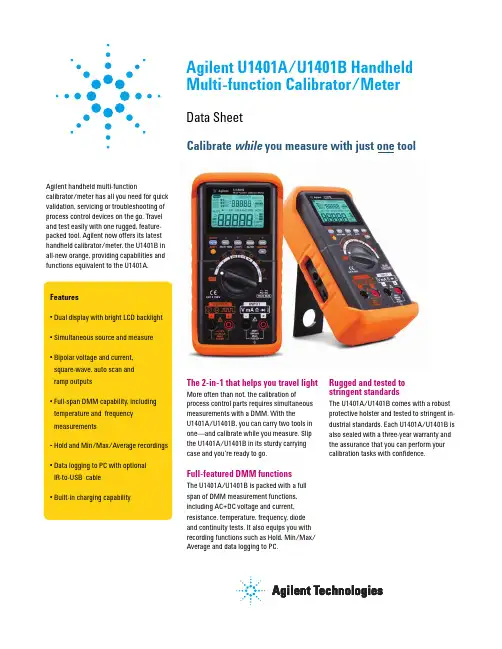
The 2-in-1 that helps you travel light Rugged and tested tostringent standards More often than not, the calibration ofprocess control parts requires simultaneous measurements with a DMM. With theU1401A/U1401B, you can carry two tools in one—and calibrate while you measure. Slip the U1401A/U1401B in its sturdy carrying case and you’re ready to go.The U1401A/U1401B comes with a robust protective holster and tested to stringent in-dustrial standards. Each U1401A/U1401B is also sealed with a three-year warranty and the assurance that you can perform yourTake a closer lookRobust protective holsterDual display with backlight 4-20 mA and 0-20 mA percentage scale readoutEasy function access through intuitive buttons and rotary switchVoltage, current, resistance, temperature, frequency, pulse width, duty cycle, diode and continuitySimultaneous source and measureHold and Min/Max/AvgrecordingsBuilt-in battery-charging capabilityBipolar voltage and current, square-wave, auto scan and rampVoltage specificationsThe accuracy is given as ± (% of reading + counts of least significant digit (LSD)) at 23 °C ±5 °C, with relative humidity less than 80% R.H., and after a warm-up period of at least five minutes. Without warm-up, an additional five counts of LSD need to be considered.[1] Input impedance: 10 M W (nominal) for the range of 5 V and above, and 1 G W (nominal) for the 50/500 mV range.[2] Accuracy can be improved to 0.05% + 5. Always use the Relative function to offset thermal effects before measuring the signal.[3] Input impedance: 1.1 M W in parallel with <100 pF (nominal) for the range of 5 V and above, and 1 G W (nominal) for the 50/500 mV range. Crest factor ~ 3.50 mV 500 mV 5 V 50 V 250 V1 µV 10 µV 0.1 mV 1 mV 10 mV0.03% + 5250 Vrms45 Hz to 5 kHz: 0.7% + 405 kHz to 20 kHz: 1.5% + 4045 Hz to 5 kHz: 0.7% + 205 kHz to 20 kHz: 1.5% + 2045 Hz to 5 kHz: 0.8% + 255 kHz to 20 kHz: 1.6% + 2545 Hz to 5 kHz: 0.8% + 705 kHz to 20 kHz: 1.6% + 700.05% + 50[2]10 µV 0.1 mV 1 mV 10 mV10 µV 0.1 mV 1 mV 10 mV1 µV1 µV500 mV 5 V 50 V 250 V500 mV 5 V 50 V 250 V50 mV 50 mV Resolution Accuracy Overload protectionRange Function DC voltage[1]AC voltage[3](True-rms: From 5% to 100% of range)AC+DC voltage[3](True-rms: From 5% to 100% of range)Resolution Accuracy Burden voltage/shunt Overload protectionRange Function DC current AC current[2](True-rms: From 5% to 100% of range)AC+DC current[2](True-rms: From 5% to 100% of range)50 mA 500 mA 50 mA 500 mA 50 mA 500 mA1 µA 10 µA 250 V, 630 mA Quick acting fuse45 Hz to 5 kHz: 0.6% + 2045 Hz to 5 kHz: 0.7% + 250.03% + 5[1]0.06 V (1 W )0.6 V (1 W )0.06 V (1 W )0.6 V (1 W )0.06 V (1 W )0.6 V (1 W )1 µA 10 µA 1 µA 10 µA[1] Always use the Relative function to offset thermal effects before measuring the signal. If this function is not used, accuracy could go down to 0.03% + 25. Thermal effects may be present due to: • Constant current, constant voltage, or square wave output.• Wrong operation. For example, resistance, diode, or mV measurement function is used to measure high voltage signals exceeding 250 V. • After battery charging has completed.• After measuring current greater than 50 mA.[2] Crest factor ~ 3�������������Resistance specificationsDiode and continuity specifications1 ms peak hold specificationsRangeRange Thermocouple type–40 °C to 1372 °C –40 °F to 2502 °F0.15% + 8 [2]1% + 8[3]0.15% + 5 [2]0.3% + 3 °C 0.3% + 6 °F0.45 mA 0.45 mA 45 µA 4.5 µA 450 nA 45 nA0.1 mV0.05% + 5Approximately 0.45 mASingle event >1 ms2% + 400 for all ranges< +4.8 VDC250 Vrms250 Vrms0.1 °C 0.1 °F500 W 5 k W 50 k W 500 k W 5 M W 50 M W0.01 W 0.1 W 1 W 10 W 0.1 k W 1 k W[1] Accuracy is specified for meter operation only, excludes thermocouple probe tolerance and with the instrument placed in the operating area for at least one hour.[2] Accuracy is specified after applying the Relative function to offset any test lead resistance and thermal effect.[3] Accuracy is specified for <60% R.H.The following resistance specifications are valid if the maximum open voltage is less than +4.8 V.For diode test, the overload protection is 250 Vrms and the instrument will beep when thereading is below 50 mV (approx). For continuity test, the instrument will beep when the resistance is less than 10.00 W .Resolution Resolution Resolution Signal width Accuracy for DC mV/voltage/current Accuracy[1]Accuracy Accuracy Test currentOpen voltage Minimum input currentOverload protectionOverload protectionKFrequency sensitivity and trigger level for voltage measurementFrequency sensitivity for current measurementDuty cycle and pulse width100 Hz 1 kHz 10 kHz 100 kHz 200 kHz50 mV 500 mV 5 V 50 V 250 V15 mV 35 mV 0.3 V 3V 30 V25 mV 50 mV 0.5 V 5 V –2.5 mA 25 mA0.1% to 99.9%5% to 95%0.01 ms to 1999.9 ms0.3% per kHz + 0.3%0.2% + 350 mA 500 mADC coupling AC coupling–20 mV 60 mV 0.6 V 6 V 60 V30 mV 80 mV 0.8 V 8 V –0.001 Hz 0.01 Hz 0.1 Hz 1 Hz 10 kHz250 Vrms0.02% + 31 Hz[1] Accuracy is based on a 5-V square-wave input to the 5 VDC range.[2] Pulse width must be greater than 10 µs and its range is determined by the frequency of the signal.Resolution Range Input rangeInput range Function Duty cycle Pulse width[2]Mode Range Accuracy at full scale [1]1 Hz to 100 kHz30 Hz to 20 kHz >100 kHz <20 kHz 20 kHz to 200 kHz Trigger level for DC couplingMinimum sensitivity (rms sine wave)Minimum sensitivity (rms sine wave)AccuracyMinimum input frequencyOverload protectionConstant voltage and current outputsSquare wave output± 1.500 V ± 15.000 V ± 25.000 mA0.5, 1, 2, 5, 10, 15, 20, 25, 30, 40, 50, 60, 75,80, 100, 120, 150, 200, 240, 300, 400, 480,600, 800, 1200, 1600, 2400, 48000.39% to 99.60% 1/Frequency 5 V, 12 V ±5 V, ±12 V0.01% + 0.2% [5]0.01% + 0.3 ms2% + 0.2 V 2% + 0.4 V0.005% + 10.010.390625%Range/2560.1 V0.1 mV 1 mV 1 µA0.03% + 30.03% + 525 mA or above [1]12 V or above[2][3][1] Loading coefficient: 0.012 mV/mA for 1.5 V output.[2] Loading coefficient: 1 µA/ V. The minimum output voltage is based on 20 mA into a 600 W load.[3] If the current loop has a 24-V power, a minimum output voltage of 24 V is achievable with a 20 mA current into a 1200-W load (using the yellow test lead).[4] The positive or negative pulse width must be greater than 50 µs to enable adjustment of duty cycle or pulse width under different frequencies. Otherwise, the accuracy and range will be different from the specifications defined.[5] For signal frequencies greater than 1 kHz, add an addition of 0.1% per kHz.Resolution Resolution Range RangeFunctionConstant voltage (CV)Constant current (CC)Frequency (Hz)Duty Cycle (%) [4]Pulse Width (ms) [4]Amplitude (V)Accuracy Accuracy Minimum output Output Accuracy is given as ± (% of output + counts of least significant digit (LSD)) at 23 °C ± 5 °C, with relative humidity less than 80% R.H., and after a warm-up period of at least five minutes.The maximum input voltage protection is 30 VDC.Both primary and secondary displays are 5-digit on the liquid crystal display (LCD) with a maximum resolution of 51,000 counts and automatic polarity indication. Backlight available. 9.6 V Ni-MH rechargeable batteries: 1.2 V x 8 pieces. No cadmium, lead or mercury. External switching adapter: AC 100 V to 240 V, 50/60 Hz input and DC 24 V/2.5 A output Battery charging: 9.3 VA typicalSourcing of constant current at 25 mA, maximum load: 5.5 VA typical on 24 V DC adapter, 2.4 VA typical on 9.6 V batteriesMeter only: 1.8 VA typical on 24 V DC adapter, 0.6 VA typical on 9.6 V batteriesAssuming fully-charged Ni-MH batteries:Meter only: 20 hours (approx.)Source/Meter: 4 hours (approx.)will appear when voltage drops below 9 V (approx.)3 hours (approx.) in 10 °C to 30 °C environmentNOTE: Prolonged charging is required if battery is fully discharged.3 readings/second, except for: AC+DC: 1 reading/secondFrequency and duty cycle (> 1 Hz): 1 reading/second Pulse width (> 1 Hz): 0.25 to 1 reading/second> 90 dB at DC, 50/60 Hz ± 0.1% (1 k W unbalanced)> 60 dB at DC, 50/60 Hz ± 0.1%0 °C to 40 °C; up to 80% relative humidity (R.H.) for temperatures up to 31 °C, decreasing linearly to 50% R.H. at 40 °C–20 °C to 60 °C with batteries removed; 5% to 80% R.H. non-condensing 0 to 2000 mIEC 61010-1:2001/EN61010-1:2001 (2nd Edition), CAN/CSA-C22.2 No. 61010-1-04, ANSI/UL 61010-1:2004, CAT II 150 V Overvoltage Protection, Pollution Degree 2IEC61326-2-1:2005/EN61326-2-1:2006, ICES-001:2004, AS/NZS CISPR11:2004 Input: 0.15 x (specified accuracy)/°C (from 0 °C to 18 °C or 28 °C to 40 °C) Output: ±(50 ppm output + 0.5 digit)/°C 192 mm x 90 mm x 54 mm 0.98 kg with holster and batteries One-year calibration cycle recommended3 years for main unit3 months for standard accessories unless otherwise specifiedDisplay Power supply Power consumptionBattery lifeCharging time Measurement rateCommon Mode Rejection Ratio (CMRR)Normal Mode Rejection Ratio (NMRR)Operating environment Storage environment AltitudeSafety compliance EMC compliance Temperature coefficient Dimensions (H x W x D)Weight Calibration WarrantyOptional accessoriesU1401A U1401BQuick Start GuideCertificate of Calibration (CoC)Calibrator/Meter standard test lead kitYellow test lead for mA Protective holsterRechargeable battery pack AC power adapter and cord(according to country)U5481A IR-to-USB cable U5491A Soft carrying case U5402A Yellow test lead for mA simulationK-type thermocouple and adapterImmersion temperature probeIndustrial surface temperature probe Air temperature probeAgilent Email Updates/find/emailupdates Get the latest information on the products and applications you select.Agilent Direct/find/agilentdirect Quickly choose and use your test equipment solutions with confidence.Remove all doubtOur repair and calibration serviceswill get your equipment back to you,performing like new, when prom-ised. You will get full value out ofyour Agilent equipment through-out its lifetime. Your equipmentwill be serviced by Agilent-trainedtechnicians using the latest factorycalibration procedures, automatedrepair diagnostics and genuine parts.You will always have the utmostconfidence in your measurements.Agilent offers a wide range of ad-ditional expert test and measure-ment services for your equipment,including initial start-up assistanceonsite education and training, aswell as design, system integration,and project management.For more information on repair andcalibration services, go to/find/removealldoubtFor more information on Agilent Technologies’products, applications or services, pleasecontact your local Agilent office. The com-plete list is available at:/find/contactusPhone or FaxAmericasCanadaLatin AmericaUnited States(877) 894-4414305 269 7500(800) 829-4444Asia PacificAustraliaChinaHong KongIndiaJapanKoreaMalaysiaSingaporeTaiwanThailand1 800 629 485800 810 0189800 938 6931 800 112 9290120 (421) 345080 769 08001 800 888 8481 800 375 81000800 047 8661 800 226 008Europe & Middle EastAustriaBelgiumDenmarkFinlandFranceGermanyIrelandIsraelItalyNetherlandsSpainSwedenSwitzerlandUnited KingdomOther European Countries:/find/contactusRevised: October 6, 200801 36027 7157132 (0) 2 404 93 4045 70 13 15 15358 (0) 10 855 21000825 010 700**0.125/minute07031 464 63331890 924 204972-3-9288-504/54439 02 92 60 848431 (0) 20 547 211134 (91) 631 33000200-88 22 550800 80 53 5344 (0) 118 9276201© Agilent Technologies, Inc. 2009Printed in USA, November 26, 20095990-3459ENProduct specifications and descriptionsin this document subject to changewithout notice./find/handheld-calibrator-meter。

安捷伦电子测量仪器使用及维护建议版本. 03.08Agilent Technologies Co. SSU-----------Be Professional , Be Expert-------目录静电的危害及防护 (3)微波接头的使用及养护常识 (12)电子测量仪器及其系统的环境要求 (16)仪器硬件故障的最终确认 (21)附录一:部分种类仪器的用户检验步骤及注意事项 (23)附录二:Agilent仪器常见故障现象及可能原因分析 (27)附录三:参考资料 (29)静电的危害及防护引言.我们在确定自己的研究课题或找到解决方案时,下一步往往就是准备好完成课题或解决方案所需的软硬件手段.而测量仪器是人们必备的硬件设施.在得到仪器后,如何高效地使用仪器,或如何避免仪器的人为损坏,能够更长时间地为我们服务,就自然而然地成为我们必须关心的环节了.静电的危害那么哪些因素可以影响或威胁到仪器的正常使用呢?了解电子测量仪器或微电子的工程师所想到的第一个词,我想必定是”静电放电”(ESD).的确,静电是我们再熟悉不过的一种现象了,除了偶而轻微电击或讨厌的静电吸附外,对我们大多数人来讲,静电似乎并不是什么了不起的问题.过去,许多从事电子工业的人也并不认为静电放电是使电子元件乃至整个电子设备损坏的一个主要原因.许多人不相信静电放电的严重性,甚至怀疑是否真正存在.这也难怪,因为要判断或检查ESD(静电放电简称-Electrostatic Dischar ge)所引起的失效比较困难,有些元件受ESD损伤后往往在经过一段时间后才失效,使人们难于追踪并确定为ESD引起的损坏.而且许多电子元件可以被远低于人能感觉的静电放电所损伤或损坏.无源器件也和有源器件一样对ESD敏感,损坏程度从性能下降直至短路那样的严重损坏.目前,许多人对自己身上常常带可观的静电以至常常受静电放电电击的现象习以为常了.可是,您知道吗?当你的手触摸及门把手或水龙头的瞬间突然感受到受电击甚至听到”啪”的一声响之时,你身上的静电已高达4000至5000伏以上了.而且.在受电击之前,你并没有任何感觉.实际上,人的身体上,衣服上经常带有几百伏到几千伏的静电.只要构成通路,积累的静电就会放电.由于在极短的时间内释放出大量的能量,常常导致电路元件损坏,因为这种放电通常大大超过许多电路元件所能承受的限度.据测试,人能感觉到”麻”时,静电电压已高达3500伏以上.高于4500伏时放电能发出响声.5000伏以上放电时可以见到火花.人感觉不到3500伏以下的静电. 现代许多高速超大规模集成电路碰到仅几十伏或更低的静电就会遭到损坏。
Agilent N4010A蓝牙测试项目说明蓝牙测试仪Agilent N4010A支持以下8大测试项目(其中一到五为发射,六到八为接收):发射项目:一、Output Power(输出功率)[]Min Avg(dBm)最小平均输出功率范围: -6dBm~10dBm(蓝牙规范是-6dBm~4dBm,但由于我们采取的是耦合测试,补偿较大,所以适当放宽)[]Max Avg(dBm)最大平均输出功率范围: -6dBm~10dBm[]Max Peak(dBm)最大峰值输出功率范围: -6dBm~23dBm二、Power Control(功率控制)注:耦合无法测试[]Min Step(dB)最小功率步长范围:2dB~8dB[]Max Step(dB)最大功率步长范围:2dB~8dB[]Min Pwr(dBm)最小功率范围:≤100dBm三、Mod Char(调制特性)[]Min df1Avg(KHz)Df1最小值范围:140KHz~175KHz[]Max df1Avg(KHz)Df1最大值范围:140KHz~175KHz[]Min df2Avg(KHz)Df2最小值范围:≥115KHz[]df2 Max PassesDf2最大通过率范围: ≥[]Min df2Avg/df1AvgDf2/Df1最小值范围: ≥四、ICFT(初始载波容限)[]Min FOffset(KHz)最小频率偏移范围:-75KHz~75KHz[]Max FOffset(KHz)最大频率偏移范围:-75KHz~75KHz五、Carrier Drift(载波频率漂移)[]Slot1 Min Drift(KHz)Slot1 最小频率漂移范围:-25KHz~25KHz[]Slot1 Max Drift(KHz)Slot1 最大频率漂移范围:-25KHz~25KHz[]Slot3 Min Drift(KHz)Slot3 最小频率漂移范围:-40KHz~40KHz[]Slot3 Max Drift(KHz)Slot3 最大频率漂移范围:-40KHz~40KHz[]Slot5 Min Drift(KHz)Slot5 最小频率漂移范围:-40KHz~40KHz[]Slot5 Max Drift(KHz)Slot5 最大频率漂移范围:-40KHz~40KHz[]Max Rate载波最大漂移速率范围:-20KHz/50μs~20KHz/50μs 接收部分:六、Single Slot Sensitivity(单时隙灵敏度)[]Single Slot BER单时隙误码率范围:<%[]Single Slot PER单时隙误包率范围:<100%七、Multi Slot Sensitivity(多时隙灵敏度)[]Multi Slot BER多时隙误码率范围:<%[]Multi Slot PER多时隙误包率范围:<100%八、Maximum Input Level(最大输入电平)[]Overall BER总的误码率范围:<%[]Overall PER总的误包率范围:<100%。
蓝芽(Bluetooth)无线技术是一种开放式的个人无线局域网络,透过短距离的射频(RF)连接,它提供不同的信息家电语音和数据的传输。
使用无线技术就不需要用到互连的接线,并可在各个设备间提供特殊的网络功能。
安捷伦科技Bluetooth技术可以让各种设备达到近乎完美的互连。
计算机和个人数字助理(PDA)可以从远程分享档案,以及进行数据库的同步化;笔记型计算机可以和行动电话连结,以收发电子邮件;蓝芽手机则是会逐渐渗透行动电话的市场,以简化免用手的操作。
全球的许多研发实验室,都已经开始在从事这项技术的应用。
由于Bluetooth还在发展的初期,因此它的测试方法将与成熟技术常用的测试方法有所不同。
测试的程序涵盖了手动介入或自订软件控制,以及简单好用的单键式量测。
Bluetooth的基本概念Bluetooth无线技术最基本的定义是,无线连接的通用规格。
因为它要用来取代接线,所以成本必须够低,操作也必须是直觉和稳定的。
这些需求将会带来许多挑战,但无线技术可以透过好几种方法,来解决这些问题。
无线单元使用的是跳频扩频(Frequency Hopping Spread Spectrum;FHSS),而设计的重点则是为了在充满干扰的ISM无线频带,提供超低功率、超低成本和最稳定的操作。
目前使用中的Bluetooth无线技术方块图有相当多种。
就传送部份而言,包括直接的VCO调变(Direct VCO Modulation),到最后RF的IQ混合。
在接收器方面,主要是将传统的鉴频器或IQ下行转换功能(Down-conversion),与模拟/数字转换功能结合在一起。
Bluetooth系统是由无线单元(Radio Unit)、基频带连结控制单元(Baseband Link Control Unit)及连结管理软件(Link Management Software)所组合而成。
它也包含部份较高阶的软件,主要的功用是确定设备之间的兼容性。
文章标题:探索赛默飞离子色谱安培检测器参数在化学分析领域,赛默飞离子色谱安培检测器参数是一个关键的主题。
本文将深入探讨该主题,为您带来全面的了解和深入的知识。
一、赛默飞离子色谱安培检测器简介赛默飞离子色谱安培检测器是用于离子色谱分析的重要仪器,主要用于检测离子和有机分子。
它具有高灵敏度、高选择性和宽线性范围的特点,被广泛应用于环境监测、食品安全、生物医药等领域。
二、赛默飞离子色谱安培检测器参数的深度解析1. 灵敏度赛默飞离子色谱安培检测器的灵敏度是衡量其检测能力的重要参数之一。
它受到多种因素的影响,如检测器的类型、工作原理、样品的性质等。
在实际应用中,我们需要根据样品的特点和分析要求来选择合适的灵敏度。
2. 选择性选择性是指赛默飞离子色谱安培检测器对目标化合物的识别能力。
它受到检测器的分辨能力、背景噪音的影响。
在实际分析中,我们需要确保检测器具有良好的选择性,能够准确识别目标化合物,同时排除干扰物质的干扰。
3. 线性范围赛默飞离子色谱安培检测器的线性范围是指其响应与样品浓度之间的关系。
通常情况下,我们希望检测器具有较宽的线性范围,能够适应不同浓度范围的样品分析。
4. 稳定性稳定性是评价赛默飞离子色谱安培检测器性能的重要指标之一。
它包括检测器的信噪比、漂移和重复性等方面。
在实际应用中,稳定的检测器能够提供准确可靠的分析结果,对于保证实验的可重复性和可比性至关重要。
三、总结与展望赛默飞离子色谱安培检测器参数对于确保分析结果的准确性和可靠性具有重要意义。
在实际应用中,我们需要充分理解这些参数的意义和影响,根据样品的特点和分析要求来选择合适的参数设置。
希望本文的介绍能够帮助您更好地理解赛默飞离子色谱安培检测器参数,从而在实验中取得更好的分析结果。
个人观点:我认为赛默飞离子色谱安培检测器参数的选择对于分析结果具有至关重要的影响。
在实际应用中,我们需要充分了解这些参数的含义和影响,根据具体的分析要求来合理设置参数,以确保分析结果的准确性和可靠性。
手环手表蓝牙射频测试指引测试目的:综合评估蓝牙模块的性能,衡量蓝牙模块的发射功率、频偏、调制特性及接收性能。
测试设备:安捷伦N4010A综测仪,安装有测试工具的电脑(默认E430)测试工具:网络连接软件Agilent Connection Expert, N4010A仪器虚拟面板AgN4010BT4_VFP,EUT射频控制软件nRFgo Studio, EUT 测试模式固件ble_app_dtm.hex测试内容:测试准备主要分为PC与测试仪连接、控制,测试模式固件烧录到EUT,测试内容包括发射平均功率、瞬时最大功率、10101010&11110000调制解析、载波频率偏移、最小接收灵敏度及最大输入电平的接收。
测试方法:1.用nordic烧录板连接电脑并通过烧录专用夹具烧录测试程序到EUT,目的为打开测试模式。
如下图2. 测试程序烧录成功后,将EUT端的串口VCC、TX、RX、GND分别接到串口板的VCC、RX、TX、GND,这里说明一下在USB转串口的串口板上必须将TX/RX与EUT的RX/TX交换连接才能正常发送和接收数据包。
3. 连接射频线于EUT,将PC与串口板连接同时将EUT端的射频线连接到N4010A。
4. 前三步工作完成后接下来进行BLE射频测试由于BLE测试的109选键测试需要在PC的对应的虚拟前面板上来完成,所以首先要将N4010A受控于PC,操作方法:用网线将PC与N4010A连接,并设置IP在同一个区域,如192.168.0.XX,这样确保PC能与N4010A直接连接。
再进行如下操作:A.打开PC已安装的工具,按照下图操作方式选择LAN连接控制方式,点击右键添加测试仪器B.添加完毕如下图,此时会增加N4010A的IP于LAN(TCPIP0)栏,同时VISA address 显示在仪器属性栏。
此处的VISA add会应用与下一步骤中C.打开安装于PC端的N4010A蓝牙测试虚拟前面板如下图,并将B步骤中的visa add copy到N4010A BT4 VFP的visa add中如下图中1标识,接着点击标识2 初始化设备,如果是第一次测试BT4点击标识7下载BT4波形文件,标识4、5选项为图中默认设置。
Agilent E4402BESA-E Seri^ Spectrum Analyzer 彳吏用万法间介宁波之猫2009-6-171简介 ..................................2. 面板 .................................2.1操作区...............................2.2屏幕显不.............................3. 各功能区的使用 ............................3.1 Control (控制)功能区.......................3・1.1 Freque ncy Channel : .................................3.1.2 Spa n X Scale ...........................................3.1.3 Amplitude Y Scale ...........................................3.1.4 In put/Output .............................................3.1.5 View/Trace ................................................3.1.6 Display ..................................................3.1.7 Mode ...................................................3.1.8 Det/Demod ................................................3.1.9 Auto Cuple ................................................3.2 Measure (测量)功能区......................3.2.1 Measure .................................................3.2.2 Meas Setup ...............................................3.2.3 Meas Con trol .............................................3.3 System (系统)功能区........................3.3.1 System ...................................................3.3.2 Preset .................................... 错误!未指定书签3.3.3 File ......................................................3.3.4 Print Setup&Print .............................................3.4 Marker (标记)功能区 ............ 错误!未定义书签3.4.1 Marker ...................................................3.4.2 Peak Search ...............................................3.4.3 Freq Count ................................................3.4.4 Marker — .................................................测试步骤举例1简介Agile nt ESA-E系列是能适应未来需要的Agile nt中性能频谱分析仪解决方案。
Agilent N4010A蓝牙测试项目说明
蓝牙测试仪Agilent N4010A支持以下8大测试项目(其中一到五为发射,六到八为接收):
发射项目:
一、Output Power(输出功率)
[1.1]Min Avg(dBm)
最小平均输出功率范围: -6dBm~10dBm(蓝牙规范是-6dBm~4dBm,但由于我们采取的是耦合测试,补偿较大,所以适当放宽)
[1.2]Max Avg(dBm)
最大平均输出功率范围: -6dBm~10dBm
[1.3]Max Peak(dBm)
最大峰值输出功率范围: -6dBm~23dBm
二、Power Control(功率控制)注:耦合无法测试
[2.1]Min Step(dB)
最小功率步长范围:2dB~8dB
[2.2]Max Step(dB)
最大功率步长范围:2dB~8dB
[2.3]Min Pwr(dBm)
最小功率范围:≤100dBm
三、Mod Char(调制特性)
[3.1]Min df1Avg(KHz)
Df1最小值范围:140KHz~175KHz
[3.2]Max df1Avg(KHz)
Df1最大值范围:140KHz~175KHz
[3.3]Min df2Avg(KHz)
Df2最小值范围:≥115KHz
[3.4]df2 Max Passes
Df2最大通过率范围: ≥99.9
[3.5]Min df2Avg/df1Avg
Df2/Df1最小值范围: ≥0.8
四、ICFT(初始载波容限)
[4.1]Min FOffset(KHz)
最小频率偏移范围:-75KHz~75KHz
[4.2]Max FOffset(KHz)
最大频率偏移范围:-75KHz~75KHz
五、Carrier Drift(载波频率漂移)
[5.1]Slot1 Min Drift(KHz)
Slot1 最小频率漂移范围:-25KHz~25KHz
[5.2]Slot1 Max Drift(KHz)
Slot1 最大频率漂移范围:-25KHz~25KHz
[5.3]Slot3 Min Drift(KHz)
Slot3 最小频率漂移范围:-40KHz~40KHz
[5.4]Slot3 Max Drift(KHz)
Slot3 最大频率漂移范围:-40KHz~40KHz
[5.5]Slot5 Min Drift(KHz)
Slot5 最小频率漂移范围:-40KHz~40KHz
[5.6]Slot5 Max Drift(KHz)
Slot5 最大频率漂移范围:-40KHz~40KHz
[5.7]Max Rate
载波最大漂移速率范围:-20KHz/50μs~20KHz/50μs
接收部分:
六、Single Slot Sensitivity(单时隙灵敏度)
[6.1]Single Slot BER
单时隙误码率范围:<0.1%
[6.2]Single Slot PER
单时隙误包率范围:<100%
七、Multi Slot Sensitivity(多时隙灵敏度)
[7.1]Multi Slot BER
多时隙误码率范围:<0.1%
[7.2]Multi Slot PER
多时隙误包率范围:<100%
八、Maximum Input Level(最大输入电平)
[8.1]Overall BER
总的误码率范围:<0.1%
[8.2]Overall PER
总的误包率范围:<100%。