N6说明书-最终版
- 格式:pdf
- 大小:4.03 MB
- 文档页数:2
北京雷根生物技术有限公司
N6培养基
简介:
Leagene N6培养基主要由硝酸钾、氯化钙、硫酸镁、磷酸盐等组成,硝酸钾工作浓度为2830mg/L 、硫酸镁工作浓度为185mg/L 、硫酸铵工作浓度为463mg/L 。
该试剂特点是成分较为简单,其中硝酸钾、硫酸铵含量较高,不含钼,主要用于培养禾谷类花药、细胞、原生质体,经高压灭菌,为无菌溶液。
该试剂仅用于科研领域,不用于临床诊断或治疗。
组成:
操作步骤(仅供参考):
1、 根据实验需求操作。
注意事项:
1、 要根据不同的材料、不同的物种,选择合适的培养基,最好通过实验获得。
2、 如需严格无菌,可再次于121℃高压灭菌15-20min 。
有效期: 6个月有效。
相关:
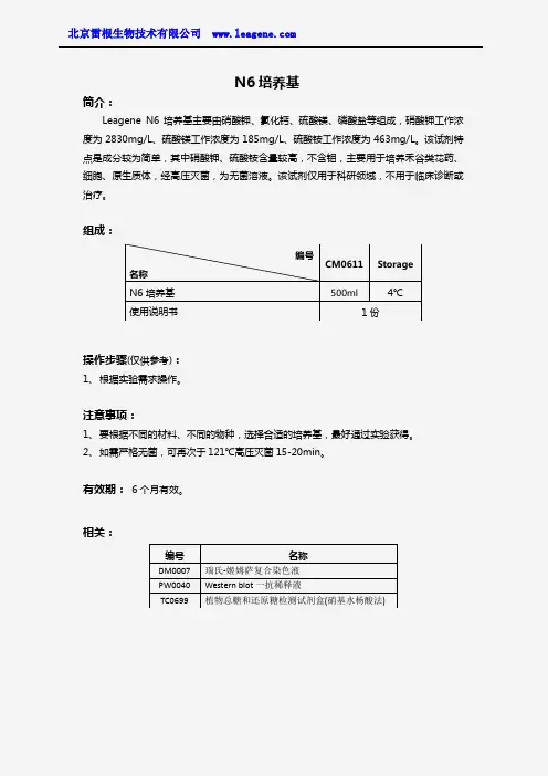
编号 名称 CM0611 Storage N6培养基 500ml 4℃ 使用说明书 1份
编号 名称 DM0007 瑞氏-姬姆萨复合染色液 PW0040 Western blot 一抗稀释液 TC0699 植物总糖和还原糖检测试剂盒(硝基水杨酸法)。

WATCH OVER YOUR WORLDFROM ANYWHERE IN THE WORLDDon’t miss a thing with true-to-life video in real-time. LorexStratus Connectivity offers instant connection anywhere yougo with no recurring fees.12/16/242/3TBChannels 960H900TVL ResolutionHDD•Tablet / smartphone viewing and playback 1 •Lorex Stratus Connectivity - 3 step setup•Superior 960H Resolution - 34% more detailed and true-to-life images 2 •Real-time recording at 30fps per channel •24/7 security-grade hard drive•Instant email alerts with snap shot attachment •Continuous, scheduled and motion recording•Advanced mobile apps with live viewing, playback, video recording, and snap shot •PC and Mac compatible•HDMI cable included for simple connection to HD TVs 3 •H.264 video compression 4•Pentaplex operation - view, record, playback, back up & remotely control the system simultaneously •PTZ cameras supported (RS485). Remotely control through App •Accurate time stamps with NTP & Daylight Savings Time •3 video outputs (HDMI, VGA and BNC) to connect multiple monitors•Automatic firmware upgrades over Internet ensure your system is secure and up to date 5DVR FEATURES:130/90FT Night Vision900TVL ResolutionIP66•1.3 Megapixel image sensor (900 TVL resolution)•Lightweight yet extremely durable Polycarbonate housing•Integrated automatic Infrared Cut Filter (ICR) ensures accurate color representation in all lighting conditions •Day/Night mode: Picture automatically switches to B&W delivering better clarity in low light conditions •BrightNight viewing with enhanced low light image sensor•Close-up recognition at night with auto light compensation prevents wash-out effect•Night vision range up to 130ft (40m) in ambient lighting & up to 90ft (28m) away in total darkness 6 •Modern two-tone design - residential and business friendly •Split glass design minimizes IR reflection•Anti-glare feature ensures clear images under strong lighting conditions •3.6mm wide-angle lens captures a wide field of view •Vandal resistant design with cable pass-through bracket •Ideal for outdoor & indoor applications (IP66 Rated) 7•Removable camera base and integrated 3ft camera cable for hassle-free and flexible installation •Versatile mounting options: ceiling, counter or wall mountable •60ft BNC/Power extension cable included per camera•Energy-efficient CEC (California Energy Commission) compliant power adapter includedCAMERA FEATURES:SEE IT ALL -IN GREATER DETAILKeep an eye on your home or business day or night with this high-resolution security camera.130/90FT Night Vision900TVL ResolutionIP66•1/3” Sony Exmor megapixel image sensor (900TVL resolution / 960H) 10 •Lightweight yet extremely durable Polycarbonate housing•Integrated automatic Infrared Cut Filter (ICR) ensures accurate color representation in all lighting conditions •Day/Night mode: Picture automatically switches to B&W delivering better clarity in low light conditions •BrightNight viewing with enhanced low light image sensor•Close-up recognition at night with auto light compensation prevents wash-out effect •Night vision range up to 130ft (40m) / 90ft (28m) 6 •Split glass design minimizes IR reflection•Anti-glare feature ensures clear images under strong lighting conditions •3.6mm wide-angle lens captures a wide field of view (92° diagonal)•ClearNight imaging technology ensures clear night vision and improves recording efficiency up to 30% •3-Axis design for wall / ceiling mounting•Ideal for outdoor & indoor applications (IP66 Rated) 7•Cold climate resistance (-4°ºF / -20°ºC minimum operating temperature)FEATURES:SEE IT ALL - IN GREATER DETAILKeep an eye on your home or business day or night with this high-resolution security camera.•Latest 960H Sony EXview™ II image sensor for excellent low light performance 8•Sony Effio™ video image processor delivers up to 700TV lines of resolution •10X Optical Zoom and 10X Digital Zoom to focus in on even the finest details •Complete area coverage with fast 360 degrees per second panning speed •Program preset viewing points when connected to a DVR•ClearNight technology with Digital Noise Reduction improves low light performance and recording efficiency by up to 30%•Accurate colors with Lorex’s automatic light filtering technology •Easy installation with pre-attached wall mount 9 •Weatherproof (IP66) rated 7•Connects to any Lorex Eco™ or Edge™ series DVR for local or remote operation •100ft all-in-one extension cable included for installation location flexibilityPTZ CAMERA FEATURES:VIEW THE ENTIRE SCENE WITH PAN-TILT-ZOOMDon’t miss a thing with advanced pan-tilt-zoom capabilities and exceptional low-light performance in a compact package.960 H700TVL Resolution10XOptical Zoom360°/SECPanning SpeedSECURITY CAMERA SYSTEMSYSTEMOperating System Linux (embedded)Pentaplex SimultaneousView, Record, Playback, Backup & Remote Monitoring Number of Channels 8/12/16/24chInputs/OutputsVideo IN 8/12/16/24 x 1Vp-p, CVBS, 75ohms, BNCVideo OUT 1 x BNCVGA OUT Y esHDMI Y esAudio IN 8 ch 8 line IN (RCA), G.711, 12/16/24 ch 4 line in(RCA),G.711Audio OUT 1 line OUT (RCA), G.711USB Port 1 at the back, 1 at the frontAlarm IN 8 Alarm INAlarm OUT 1 Alarm OUTVideo Output Resolution 1920x1080 HDMI, 1440x900, 1280x1024, 1024x768PTZ control RS-485 Pelco D & P ProtocolDisplayLive Display 8 ch: 1, 4, 912 ch: 1, 4, 9, 1216 ch: 1, 4, 9, 1624 ch: 1, 4, 9, 16, 24Live Display Speed 8 ch: 240 NTSC, 200 P AL12 ch: 360 NTSC, 300 P AL16 ch: 480 NTSC, 400 P AL24 ch: 720 NTSC, 600 P ALOSD ON/OFFSystem Navigation USB Mouse, IR Remote Controller, Front PanelMotion Area Setting Adjustable grid (30x44) NTSCAdjustable grid (36x44) P ALSensitivity levels 8Firmware Upgrade Automatic over the Internet & via USB device and NetworkUser Authority By user groupTime Synchronization Auto time sync by NTP serverRECORDINGVideo Compression H.264Audio Compression G.711Recording Resolution NTSC:960H:960x480, 960x240, 480x240D1 mode: 720x480(D1), 720x240(2CIF), 360x240(CIF)P AL:960H: 960x576, 960x288, 480x288D1 mode: 720x576(D1), 720x288(2CIF), 360x288(CIF) Recording Resolution Setting Per camera for different resolutionsRecording Quality Control 3 levelsRecording Schedule By hour, by day, by recording mode, by motion, by alarm, by chPre Recording Max.10 SecsPost Recording Max.5 MinutesReliability W atch-Dog, Auto-recovery after power failure Covert Video Y esPLA YBACKPlayback Channel 8 ch: 1~8 Adjustable, 12 ch: 1~12 Adjustable,16/24 ch: 1~16 AdjustablePlayback Speed V ariableMax 16xPlayback Players Backup PlayerSearch By time & eventLog Search Up to 100,000 lines for system, configuration changes,motion/alarm detected, account, record and storage Audio Play Y esSTORAGE & ARCHIVEStorage 8/12/16 ch: Up to 1 HDD’s (SA T A)24 ch: Up to 2 HDD’s (SA T A)Maximum Capacity 8/12/16 ch: up to 1 x 4TB24 ch: up to 2 x 4TBBackup Media USB Flash Drive & HDDBackup File Format H.264 file (A VI generator included) CONNECTIVITYCloud Connection Lorex Stratus ConnectivitySupported Operating Systems Windows™Mac OSRemote Software Client Software (PC) & Safari (Mac)Email notification T extwith snapshotInstant Smart Phone iPad®, iPhone®, Android™& T ablet Support †DDNS Free Lorex DDNSSystem Configuration Full setup configuration over networkPorts Programmable by UserNetwork Protocol TCP/IP / DHCP / UDP / DDNS / PPPoENetwork Interface 10/100-Base-TX, RJ-45Network Speed Control 48Kb ~ 8MB/sec.GENERALPower Consumption Approx. 10 watts (no HDD included)Supply V oltage 8/12/16 ch: 100V AC-240V AC, 12VDC , 2A,50/60Hz24 ch: 100V AC-240V AC, 12VDC , 5A,50/60HzUnit Dimensions 8/12/16 ch: 11.8”/300mm x 9.9”/251mm (W x D x H) x 2.4”/60mm24 ch: 14.9” /380mm x13.3”/340mm x1.9”/50mmUnit W eight (KGs) 8 ch: 1.7 kg/3.75 Lbs12 ch: 1.95 kg/4.3 Lbs16 ch: 2.0 kg/4.43 Lbs24 ch: 3.54 kg/7.8 LbsOperating temperature 32° ~ 104° F / 0° ~ 40° CHumidity10 ~ 90% NCImage Sensor 1/3” 1.3 MP Sony Exmor® CMOS Video Format NTSCEffective Pixels H: 1305 V: 1049Resolution 900 TVL Scan System 2:1 Interlace Sync System I nternal S / N Ratio 48dB (AGC Off)Iris AESAES Shutter Speed 1/60 ~ 1/100,000 sec.Min. Illumination 0.01 Lux without IR LED0 Lux with IR LED Video Output Composite 1.0Vpp @ 75ohm Lens / Lens T ype 3.6mm F2.0 / Fixed FOV (Diagonal) 92°°T ermination BNC T ype IR LED Qty . / T ype 24 pieces / 850nm Night Vision Range 130ft (40m) / 90ft (28m)Power Requirement 12V DC ±10%Power Consumption Max. 320mA (w / IR)Operating T emp. Range –4° ~ 122°F / –20° ~ 50°C Operating Humidity Range < 80% RH Environmental Rating I P66Weight (including stand)0.6lbs / 0.2kg CVC7721PK4BImage Sensor: 1/3” Sony Ex-View HAD CCD II Video Format: NTSCEffective Pixels: 976(H) x 494 (V)Resolution: up to 700 TVLRange: 360° Pan (Endless)160° Tilt (Auto-Flip)Pan/Tilt Speed: Max 360°/Sec.Zoom: 10x Optical Zoom & 10x Digital Zoom Protocol: Pelco-D, Pelco-P Min. Illumination: 0.7 Lux in Color0.02 Lux in Black and White Lens/Lens T ype: Auto Focus / 3.8-38mm F 1.8S/N Ratio: 50db (AGC Off)Iris: Auto Iris Day/Night: IR Cut Filter (ICR)T ermination: BNC Video / RS485 / DC Power Video Output: Composite 1.0Vpp @ 75ohm Power Requirement: 12V DC ±10%Power Consumption: Max. 850mAOperating T emperature Range: -4°F ~ 122°F / -20°C ~ 50°C Operating Humidity Range: within 90%RH Indoor/Outdoor: Both (IP66)Weight:2.9lbs / 1.3kg LZC7092BDimensions:8/12/16 Channel DVRs24 Channel DVR380mm/14.9”300mm/11.8”CVC7721PK4BLZC7092BLDC7722PK4BImage Sensor 1/3” Sony Exmor™ Megapixel CMOS Video Format NTSCEffective Pixels H: 1305 V: 1049Resolution 900 TVL Scan System 2:1 Interlace Sync System I nternal S / N Ratio 48dB (AGC Off)Iris AESAES Shutter Speed 1/60 ~ 1/100,000 Sec.Min. Illumination0.01 Lux without IR LED0 Lux with IR LED Video Output Composite 1.0Vpp @ 75ohm Lens / Lens T ype 3.6mm F2.0 / Fixed FOV (Diagonal) 92°°T ermination BNC T ype IR LED Qty . / T ype 24 IR LEDs / 850nm Night Vision Range 130ft (40m) / 90ft (28m)Power Requirement 12V DC ±10%Power Consumption Max. 320mA (w / IR)Operating T emp. Range –4° ~ 122°F / –20° ~ 50°C Operating Humidity Range < 80% RH Environmental Rating I P66Weight (including stand)0.7lbs / 0.3kgLDC7722PK4BProduct Information:Disclaimers:1. Requires a high speed internet connection and a router (not included). An upload speed of 1Mbps is recommended for the best video performance. Up to 3 devices may connect to the system at the same time. For the latest list of supported apps and devices, check /support.2. Optimized when used with 960H compatible cameras. DVR is backwards compatible and supports different camera inputs: standard resolution and 960H.3. High definition recording not supported, recording resolution is limited to a maximum of 960x480 per channel. Image quality and resolution is dependent on the type of camera connected to the DVR.4. Recording time may vary based on recording resolution & quality, lighting conditions and movement in the scene.5. Both firmware and software must be updated to latest version to ensure remote connectivity. Always update to the latest software (available at ) after upgrading the DVR firmware.6. Stated IR illumination range is based on ideal conditions in typical outdoor night time ambient lighting and in total darkness. Actual range and image clarity depends on installation location, viewing area and light reflection / absorption level of object.7. Not intended for submersion in water. Installation in a sheltered location recommended.8. This camera features an ultra-low light sensitive image sensor and therefore does not feature Infra-Red LEDs. The camera requires ambient lighting (for example, street/building lighting, star or moon light) to render a night time image. In total darkness (zero Lux) the camera will not produce a night time image and therefore the camera should not be installed in completely dark areas.9. Wall mount only. Ceiling mount not supported.10. When connected to a 960H-capable DVR.All trademarks belong to their respective owners. No claim is made to the exclusive right to use the trademarks listed, other than the trademarks owned by Lorex Technology Inc. We reserve the right to change MODEL CONFIGURATION PACKAGE W x D x H Inches & mm WEIGHT CUBE UPC Code LH16162TC12Z1B16 ch ECO6 DVR with 2TB HDD & 12 x 900TVL Cameras (CVC7721PK4B) & 1 x 700TVL PTZ Camera (LZC7092B)Brown Box508mm x 444mm x 513mm 20.0” x 17.5” x 20.2”(estimated)21.8 kg/48.2 lbs (estimated)0.04cbm / 1.62cft6-95529-00115-9LH16243TC129B 24 ch ECO6 DVR with 3TB HDD & 12 x 900TVL Cameras (CVC7721PK4B)Brown Box 508mm x 444mm x 513mm 20.0” x 17.5” x 20.2”(estimated)17.6 kg/38.9 lbs (estimated)0.04cbm / 1.62cft 6-95529-00176-0LH16162TC169B 16 ch ECO6 DVR with 2TB HDD & 16x 900TVL Cameras (CVC7721PK4B)Brown Box 487mm x 393mm x 370mm 19.2” x 15.5” x 14.6”(estimated)13.6 kg/30 lbs (estimated)0.07cbm / 2.51cbf 6-95529-00163-0LH16122TC89B 12 ch ECO6 DVR with 2TB HDD & 8x 900TVL Cameras (CVC7721PK4B)Brown Box 482mm x 304mm x 342mm19” x 12” x 13.5”9.8 kg/21.65 lbs0.011cbm / 0.39cbf 6-95529-00181-4LH16162TC129B 16ch ECO6 DVR with 2TB HDD & 12 x 900TVL Cameras (CVC7721PK4B)Brown Box406mm x 431mm x406mm16” x 17” x 16”13.8 kg/30.6 lbs0.04cbm / 1.62cft 6-95529-00202-6LH16162TC889B 16 ch ECO6 DVR with 2TB HDD & 8x 900TVL Bullet Cameras (CVC7721PK4B), 8x 900TVL Dome Cameras (LDC7722PK4B)Brown Box487mm x 393mm x 370mm 19.2” x 15.5” x 14.6”13.6 kg/30 lbs (estimated)0.07cbm / 2.51cbf 6-95529-00203-3DVR Includes 16 OR 24 Channel DVR with Pre-Installed HDD, HDMI Cable, Remote Control, Power adapter, Mouse, Ethernet Cable, Quick Start Guides Bullet Camera Includes12 x Cameras, 12 x Mounting kit with Allen key, 12 x 60ft BNC / power extension cables, 3 x 4-in-1 Power adaptersPTZ Camera Includes1 x PTZ Camera, 1x 100ft BNC/Power/RS485 Cable, 1 x 13V DC power adapter, 1 x Wall Mount (pre-attached), 1 x Instruction Manual, 1 x Mounting kitDVR Inputs & Outputs。
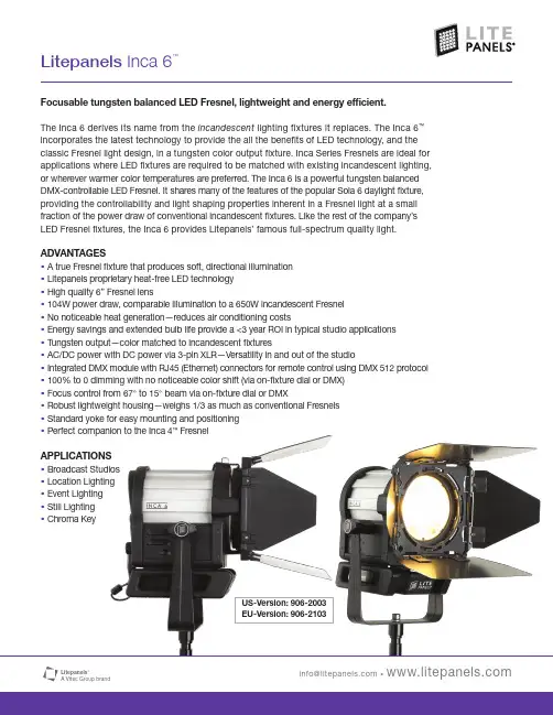
Focusable tungsten balanced LED Fresnel, lightweight and energy efficient.The Inca 6 derives its name from the incandescent lighting fixtures it replaces. The Inca 6™incorporates the latest technology to provide the all the benefits of LED technology, and the classic Fresnel light design, in a tungsten color output fixture. Inca Series Fresnels are ideal for applications where LED fixtures are required to be matched with existing incandescent lighting, or wherever warmer color temperatures are preferred. The Inca 6 is a powerful tungsten balanced DMX-controllable LED Fresnel. It shares many of the features of the popular Sola 6 daylight fixture, providing the controllability and light shaping properties inherent in a Fresnel light at a small fraction of the power draw of conventional incandescent fixtures. Like the rest of the company’s LED Fresnel fixtures, the Inca 6 provides Litepanels’ famous full-spectrum quality light.ADVANTAGES•A true Fresnel fixture that produces soft, directional illumination•Litepanels proprietary heat-free LED technology•High quality 6” Fresnel lens•104W power draw, comparable illumination to a 650W incandescent Fresnel•No noticeable heat generation—reduces air conditioning costs•Energy savings and extended bulb life provide a <3 year ROI in typical studio applications •Tungsten output—color matched to incandescent fixtures•AC/DC power with DC power via 3-pin XLR—Versatility in and out of the studio•Integrated DMX module with RJ45 (Ethernet) connectors for remote control using DMX 512 protocol •100% to 0 dimming with no noticeable color shift (via on-fixture dial or DMX)•Focus control from 67° to 15° beam via on-fixture dial or DMX•Robust lightweight housing—weighs 1/3 as much as conventional Fresnels•Standard yoke for easy mounting and positioning•Perfect companion to the Inca 4™FresnelAPPLICATIONS•Broadcast Studios•Location Lighting•Event Lighting•Still Lighting•Chroma KeyUS-Version: 906-2003EU-Version: 906-2103Specifications subject to change without notice.INCA 6 SPECIFICATIONSSize 11 x 10 x 15" / 28 x 25 x 38cm Weight 9.10 lbs / 4.13kgFresnel Lens 6 inch (15.24cm)Maximum Power Draw 104W Power Requirements 14-28VDC / 100-240VACPower Supply AC/DC 120-240VAC DC power via 3-pin XLR Includes 8-way barn doors, yoke with junior pin adapter, power supplyOPTIONAL ACCESSORIES•5-piece Gel/Filter Set w/Carrying Bag •RJ45 to 5-pin XLR Conversion Cable •Pole Assisted Y okeINCA 6 PHOTOMETRICS DATAl i t e p a n e l s _i n c a _6_b r o a d c a s t _l e d _l i g h t _o n e _s h e e t _i n f o _L e t t e r _ 9.28.12 _m fPrinted in the USA The Litepanels DifferenceFull spectrum quality soft light with visually accurate color temperature The widest variety of LED fixtures and flexible AC or DC power options Smooth dimming from 100% to 0 with no color shiftFlicker-free performance at any frame rate or shutter angle Cool to the Touch ™operation with innovative thermal dynamics Controlled current management for long LED lifeEfficient power management for low power consumption and high reliability Developed and assembled in Los Angeles, CALitepanels was founded in 2001 by 5 professional gaffers and engineers who saw the future and pioneered LED lighting for motion pictures and television. Their Emmy ®award-winning technology has now been used on thousands of productions worldwide. Backed by the Vitec Group’s legacy of 100+ years in the broadcast andproduction industry, Litepanels continues to expand its suite of flicker free, color accurate, soft light that talent and Lighting Directors admire. These environmentally friendly fixtures practically pay for themselves with power savings and long life, setting a new standard in professional lighting.FootcandlesFootcandles。
诺基亚N6智能手机使用说明1 开机拿着手机,手机右边上方有两个键,一个大的,一个小的,按下小的键(即电源/锁定键),长按,等一会儿,屏幕上会出现字,等待,等待,等待,最后会出现时间,就是开机了。
2 解锁开机后,要“解锁”后才能用手机。
屏幕下方有“向上滑动解锁”的文字,遵照说明,用手指按住屏幕,向上滑动一段距离,就“解锁”了。
“解锁”后会出现彩色图标如“电话”等,就可以用了。
3 主要操作手法智能手机只有最下部有一个按键,其余处无按键了。
要操作时,一般是手指点住屏幕,点击,按住向上滑动,按住向下滑动,按住向左滑动,按住向右滑动。
点击,只要用手指点击一下即可。
一般要点击在“图标”的中部,当然,稍微靠边框也是可以的。
不熟练时,点击或按住屏幕时,可以稍用力些按屏幕,不要担心屏幕按坏。
多练习就熟练了。
4 和按键式手机的功能最大不同按键式手机的功能基本是固定的,基本不能增加功能。
智能手机的功能可以被认为是无限多的,除了基本的功能:打电话、看短信外,可以增加许许多多的功能,例如:天气预报、时钟等。
要增加智能手机的功能,需要经过一定的操作,新手暂用现有功能。
5 学习智能手机的使用方法智能手机一般没有使用说明书,主要原因是智能手机的功能无限多,没办法用说明书来细说。
学习智能手机的使用方法,主要有两种方法:1、多用,不要怕按坏。
2、看教学视频。
教学视频也只能讲一部分。
3、左滑,再左滑,至右边第二屏,寻找“360帮帮”图标,点击该图标,女儿可以在武汉指导在监利的爸爸使用手机。
具体请见本文档“360帮帮”。
智能手机中用到的一些专业名词,虽然不太好理解,多问也慢慢会有感觉。
6 智能手机的2个网络智能手机有如下2个网络,有3种使用情况:1、打电话和发短信的网络。
按键式手机就用的这个网络。
一般分为联通网络、移动网络和电信网络。
本机可以使用。
本机2个月后开始计费。
打电话是按分钟计费,发短信是按条计费。
2、互联网的网络。
只有开通互联网的网络,才能用互联网的功能。
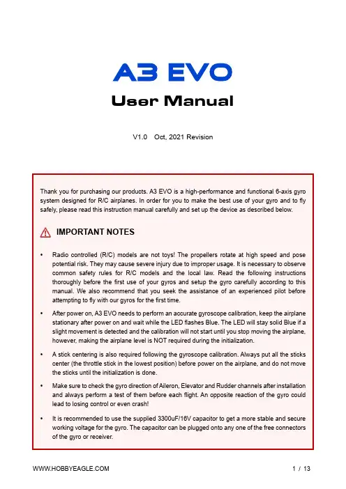
User ManualV1.0 Oct, 2021 RevisionThank you for purchasing our products. A3 EVO is a high-performance and functional 6-axis gyro system designed for R/C airplanes. In order for you to make the best use of your gyro and to fly safely, please read this instruction manual carefully and set up the device as described below.IMPORTANT NOTES•Radio controlled (R/C) models are not toys! The propellers rotate at high speed and pose potential risk. They may cause severe injury due to improper usage. It is necessary to observe common safety rules for R/C models and the local law. Read the following instructions thoroughly before the first use of your gyros and setup the gyro carefully according to this manual. We also recommend that you seek the assistance of an experienced pilot before attempting to fly with our gyros for the first time.•After power on, A3 EVO needs to perform an accurate gyroscope calibration, keep the airplane stationary after power on and wait while the LED flashes Blue. The LED will stay solid Blue if a slight movement is detected and the calibration will not start until you stop moving the airplane, however, making the airplane level is NOT required during the initialization.• A stick centering is also required following the gyroscope calibration. Always put all the sticks center (the throttle stick in the lowest position) before power on the airplane, and do not move the sticks until the initialization is done.•Make sure to check the gyro direction of Aileron, Elevator and Rudder channels after installation and always perform a test of them before each flight. An opposite reaction of the gyro could lead to losing control or even crash!•It is recommended to use the supplied 3300uF/16V capacitor to get a more stable and secure working voltage for the gyro. The capacitor can be plugged onto any one of the free connectors of the gyro or receiver.Use one of the supplied double-sided tape to attach the gyro to your airplane firmly. For best performance, the gyro should be mounted as close to the C.G. as possible, and the housing edges must be aligned exactly parallel to all three rotation axes of the plane. The gyro can be attached flat or upright, and even upside down, however, you have to ensure that the shorter side with the setting button always points toward the heading direction of the airplane, otherwise the gyro will not work normally in LEVEL and HOVER modes.①Flat, face up ②Flat, face down③Upright, button up ④Upright Inverted, button downNOTES•Never use the hot-melt glue or nylon ties to fix the gyro onto the airplane!•You need only one piece of the tapes each time, a soft or thick mounting may probably impact the performance of the gyro.•The gyro is a sensing device, please make enough space around it and keep as far away from other electronic devices or wires as possible.NOTES•[MODE] is used for flight mode switching of the gyro, connect it to a 3-way switch channel of the receiver to switch the flight mode in flight.•[SBUS/PPM/G] is used for remote master gain adjusting, connect it to a proportional channel of a volume or slide lever of the transmitter to tune the master gain in flight.•The ESC or throttle servo is connected to the throttle channel of the receiver directly without passing through the gyro.•Pay attention to the polarity of the plugs. The orange signal line must always be on the top and the brown on the bottom.St andard PWM Receiver ConnectionSingle-line Receiver ConnectionA3 EVO supports PPM and Futaba S.Bus serial receivers which allows you to connect the gyro to the receiver with one single wire. When using a specific type of these receivers the appropriate type of receiver channel allocation will be preset in the A3 EVO. Please refer to the table below and check if yourradio transmits the channels in the correct order. If you use a standard PWM receiver with standard wiring layout the channel mapping does not apply. When A3 EVO is operating in single line receiver mode, the [THR Out/AIL] can be used as the throttle output channel for the ESC or the throttle servo if a mini receiver is being used which has no additional output connectors.Please note that the Remote Master Gain is disabled in single line mode as default. Choosea channel number for gain channel in item 11 of the Setup Menu to activate this feature if needed.Table 1: Default Channel Mapping for Single Line ReceiversAIL ELE THRPPM Receiver CH1CH2CH3CH4CH5-Futaba S.Bus (FrSky SBUS or WFLY WBUS)CH1CH2CH3CH4CH5-A3 EVO provides 4 flight modes which can be switched by a 3-position switch of the transmitter during flight. We have provided you with 4 different mode allocation corresponding to the 3 positions of the switch in Item 7 of the Setting Menu, the default setting is MODE 1: NORMAL – LEVEL - HOVER. The color of the LED shows the current flight mode of the gyro while in use.Table 2: Colors of the LED for Flight ModesTable 3: Flight Mode Allocations1. GYRO OFF ModeWhen operating in GYRO OFF mode the gyro will be deactivated completely, and the airplane will be completely under the control of your transmitter as it was before installing the gyro. This mode is usually used for testing purpose only.2. NORMAL ModeThe NORMAL mode, also known as the ‘Rate mode’, is the most basic function of the gyro. It works based on the rotation rate control of each axis of the airplane. When operating in this mode, the gyro will only correct currently occurring rotational movements, a momentary reaction will be applied to the servos when the airplane rotating on corresponding axis, after rotation the servos will move back to their neutral position as soon as the airplane standing still immediately. The NORMAL mode can be used with nearly any size and type of airplanes. It can effectively improve the stability and precision of the airplane and reduce the stall point specially.3. LEVEL ModeThe LEVEL mode is also known as the ‘Auto-Level mode’, ‘Auto-Balance mode’ or ‘Horizon mode’. When operating in this mode, the airplane will be brought to horizontal position automatically when releasing the sticks. Different from the ANGLE mode, there is no maximum angle limitation in this mode and the airplane will be stabilized only when there is no specific control input from aileron and elevator sticks. This mode can be used if the pilot becomes disoriented and would like to save the airplane from crashing.4. HOVER ModeThe HOVER mode, also known as the ‘Auto-Hover mode’, provides the same functionality as the LEVELmode. The only difference is that when you release the sticks, the airplane will be brought to vertical position (nose up) and keeps hovering. This mode is designed to help you to learn hovering maneuver and reduce the probability of crashing.Basic GainThere are 3 trimming potentiometers on the front of the A3 EVO. They are used to adjust the basic gain of the gyro for Aileron, Elevator and Rudder separately. Clockwise for increase, anticlockwise for decrease. Basic gain determines the momentary reaction strength of the gyro. In general, the higher the gain the harder the airplane will stop after rotation and the more stable and precise the airplane will fly. But if the gain is too high the airplane will tend to oscillate at high frequency on the corresponding axis. If too small, the operation and stability will not be so good and the airplane does not stop precisely and overshoots. The gyro will be deactivated completely if you turn the basic gain to 0%.For the first flight test it is recommended to start with a lower basic gain setting (e.g. 30%) and switch the gyro to NORMAL mode. In case the airplane starts to oscillate in flight then reduce the gain of the corresponding axis. If the control feels weak and imprecise and does not hold position when stopping then increase the gain, according to this approach, fine tune the basic gain until you get the best performance.Remote Master GainThe [SBUS/PPM/G] is used to control the remote master gain for parallel PWM receiver. You can make a linear adjustment by using a volume or slide lever on your transmitter or make a 3-level gain selection using a 3-position switch. This function is optional, the master gain will always default to 100% if you do not connect it. Master gain will not affect the basic gain setting on the gyro.Setup MenuTo get into the Setup Menu, press and hold the button for about 2 seconds until the LED starts flashing Blue and Red quickly. The Setup Menu contains 11 setting functions which normally only need to be setup once after installation.Function SelectionIn the Setup Menu, the LED will flash Blue and Red several times every 3 seconds in a loop and the number of times LED flashes shows at which function item you are currently. For example, one Blue and Red flashing means the first setting “Aileron Gyro Direction”, after waiting about 3 seconds, a twice Blue and Red flashing means the second setting “Elevator Gyro Direction”, and so on.Option SwitchingWhen you reach the function that you wish to operate in, short press the button to get into it. After entering in, the current selected option is indicated by the color of the LED. Each short press of the button advances the option to the next value. After you finish making your selection, just wait for 5 seconds until the LED starts blink quickly which indicates that the modified is saved and then you will be brought back to the Setup Menu level automatically. If you do not want to change anything, just wait for timeout without any operation.Exit of MenuTo exit the menu just keep the button pressed for 2 seconds again until the LED starts flashing Blue and Red quickly.Blue&Red Flash ing 1-3. Gyro DirectionThe top 3 items of the Setting Menu is used to reverse the gyrodirection for Aileron , Elevator and Rudder . The color of LEDshows you the gyro direction currently selected, the default setting is Normal (Solid Blue). Each short press of the buttonwill switch between Normal and Reversed . After you finishmaking your selection, just wait for 5 seconds until LED starts blink quickly which indicates that the modified is saved and then you will be brought back to the Setup Menu level automatically.VERY IMPORTANT!It is extremely important to make sure that the gyro reacts in the correct direction for each channel before flight. An opposite reaction of the gyro could lead to losing control or even crash!Check the gyro direction for Aileron Quickly move the right wing downward around the roll axis, the right aileron surface should flap down and the left flap up as shown below.Check the gyro direction for Elevator Quickly move the nose of the airplane downward around the pitch axis, the elevator surface should flap up as shown below.Check the gyro direction for Rudder Quickly move the nose of the airplane to the left around the yaw axis, the rudder surface should flap right as shown below.4. Wing TypeThe 4th item of the Setup Menu is used to setup the wingtype. A3 EVO supports standard fixed-wing, flying-wing(delta-wing) and V-tail. The color of LED shows you the wing type currently selected. The default setting is Standard(Solid Blue), each short press of the button will switch to thenext type. After you finish making your selection, just wait for 5 seconds until LED starts blink quickly which indicatesthat the modified is saved and then you will be brought back to the Setup Menu level automatically.NOTES• Make sure that there are no mixing functions active on your transmitter. Have a look at the radio’s servo monitor and verify that each stick controls only one output channel. • If two aileron servos are being used, please connect a Y-extended lead to [OUT1]. •Most flying-wings have no rudder, in this case, [RUD] is unnecessary to connect.Servo Connection Illustration5. Receiver TypeThe 5th item of the Setup Menu is used to choose the receiver type. The color of LED shows you the receiver type currently selected. The default setting is PWM Receiver (Solid Blue), each short press of the button will switch to the next value. After you finish making your selection, just wait for 5 seconds until the LED starts blink quickly whichindicates that the modified is saved and then you will be brought back to the Setup Menu level automatically.Restart the gyro to make the new receiver type setting take effect!6. Mount Orient ationThe 6th item of the Setup Menu is used to setup themounting orientation of the gyro. The color of LED showsyou the orientation currently selected. The default setting isFlat, face up (Solid Blue), each short press of the button willswitch to the next value. After you finish making yourselection, just wait for 5 seconds until LED starts blinkquickly which indicates that the modified is saved and thenyou will be brought back to the Setup Menu levelautomatically.The setting here should be the same as the mounting orientation of your unit installed in the airplane, otherwise the gyro will not work normally.7. Flight Mode AllocationThe 7th item of the Setup Menu is used to select the flightmode allocation definition for the 3-position switch. Thecolor of LED shows you the orientation currently selected.The default setting is Mode-1 (Solid Blue), each short pressof the button will switch to the next value. After you finishmaking your selection, just wait for 5 seconds until LEDstarts blink quickly which indicates that the modified issaved and then you will be brought back to the Setup Menulevel automatically.See “Table 3: Flight Mode Allocations” on page 5 for description of each mode.8. Servo FrequencyThe 8th Item of the Setup Menu is used to select the working frequency of the servos. The color of LED shows you the frequency currently selected. The default setting is 50Hz (Solid Blue), each short press of the button will switch to the next value. After you finish making your selection, just wait for 5 seconds until LED starts blink quickly which indicates that the modified is saved and then you will be brought back to the Setup Menu level automatically.Please note that the analog servos can only work with 50Hz. If you do not know what the maximum update rate that is tolerated by your servos never use more that 50Hz. The higher the frequency the better it is for the flight performance of the gyro but you must check the servo specifications before increasing the setting. Otherwise, the servos may get damaged!9. Level CalibrationWhen flying in LEVEL mode, A3 EVO needs to know the angle of the airplane in both roll and pitch directions, this is achieved by calculating the attitude of its own. A small angle deviation caused by installation can lead to an unexpected behavior when flying in LEVEL mode. For this reason, a level calibration is recommended to offset the error caused by installation and to establish a proper level reference of your airplane after installing the gyro.Before calibrating, the airplane should be placed on the horizontal ground and make the wing parallel to the ground. Make the airplane slightly nose-up because a certain elevation angle is usually required to maintain level flight for most airplanes. Short press the button when you reach the 9th item of the Setup Menu, then LED will start blink Blue rapidly for several seconds, do not move the airplane and keep its attitude until the calibration is done.10. Hover CalibrationAs a same reason, a hover calibration is recommended to perform after installation if you want to fly with HOVER mode. The procedure is quite similar to that of level calibration. The only difference is that before calibrating, you need to lift the airplane and make it vertical to the ground instead of putting it on the ground.Short press the button when you reach the 10th item of the Setup Menu, then LED will start blink Blue rapidly for several seconds, do not move the airplane and keep its attitude until the calibration is done.11. Remote Master Gainthe remote master gain function for SBUS or PPM receivermode. The master gain is disabled as default when leavingthe factory, you need to choose either channel 6 or channel7 as the gain channel to activate this feature if needed.* F actory ResetTo restore the gyro to factory default settings, press and hold the button while turn on the power of the gyro, release it when LED starts flash Blue and Red. (FYA: the button needs to be hold for more than 4 seconds), after successfully entering the program the LED will remain flashing Blue, press and hold thebutton again for about 2 seconds until the LED starts flash Blue quickly, release the button to confirm thereset. After a successful reset the gyro will start the initialization automatically.* Accelerometer CalibrationBefore leaving the factory, every unit has been carefully tested and calibrated. Usually, you do not need to perform a calibration of the accelerometer during use. However, in some specific cases, we would suggest you re-calibrate the accelerometer to obtain better performance, these include temperature changes those will probably cause the mechanical characteristics changes of the sensor, or replacement of new sensor, etc. The calibration should be done on a horizontal desktop and the gyro needs to be removed from the airplane.Entering the Calibration ProgramTo access the accelerometer calibration program, press and hold the button while turn on the power of the gyro, release it when LED turns Blue and Red.Calibration StepsA3 EVO uses a quick approach for accelerometer calibration, there are only 2steps corresponding to both sides of Z axis of the unit required to becalibrated. Each step will take about 2 seconds. While calibrating, the LED willflash Blue several seconds and then light up solid in Blue. Do not move thegyro until the calibration is done.①Put the gyro flat and face up on the table and make it parallel to thedesktop. short press the button, do not move the gyro while the LED isflashing Blue quickly.②Put the gyro flat and face down on the table and make it parallel to thedesktop, short press the button, do not move the gyro while the LED isflashing Blue quickly.③After you have finished the 2 steps above, the LED will flash Blue andRed once which indicates that the calibration is complete, after a successfulcalibration the gyro will start the initialization automatically.Blue, Flashing Power-on initialization and self-test Solid Blue NORMAL ModeSolid Red LEVEL ModeSolid Blue&Red HOVER ModeLED Off GYRO OFF ModeRed, Slow Flashing No receiver signal detected Blue, Fast Flashing Calibrating or testingRed, Fast Flashing Gyroscope sensor error。
设计任务书设计任务:1 按工艺动作过程拟定机构运动循环图2 进行回转台间歇机构,主轴箱道具移动机构的选型,并进行机械运动方案评价和选择3 按选定的电动机和执行机构的运动参数进行机械传动方案的拟定4 对传动机构和执行机构进行运动尺寸设计5 在2号图纸上画出最终方案的机构运动简图6 编写设计计算说明书设计要求:1 从刀具顶端离开工件表面65mm位置,快速移动送进了60mm后,在匀速送进60mm (5mm刀具切入量,45mm工件孔深,10mm刀具切出量),然后快速返回。
回程和工作行程的速比系数K=2。
2 生产率约每小时60件。
3 刀具匀速进给速度2mm/s,工件装、卸时间不超过10s。
4 执行机构能装入机体内。
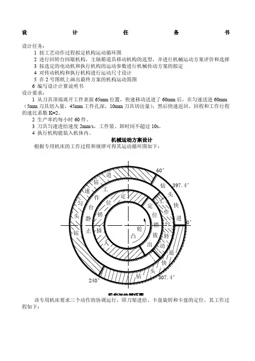
机械运动方案设计根据专用机床的工作过程和规律可得其运动循环图如下:机构运动循环图该专用机床要求三个动作的协调运行,即刀架进给、卡盘旋转和卡盘的定位。
其工作过程如下:要确保在刀具与工件接触时卡盘固定不动,刀具退出工件到下次接触工件前完成卡盘旋转动作。
几个动作必须协调一致,并按照一定规律运动。
机械总体结构设计一、原动机构:原动机选择Y132S-4异步电动机,电动机额定功率P=5.5KW,满载转速n=1440r/min 。
二、传动机构:传动系统的总传动比为i=n/n 6,其中n 6为圆柱凸轮所在轴的转速,即总传动比为1440/1。
采用涡轮蜗杆减速机构(或外啮合行星减速轮系)减速。
三、执行部分总体部局:执行机构主要有旋转工件卡盘和带钻头的移动刀架两部分,两个运动在工作过程中要保持相当精度的协调。
因此,在执行机构的设计过程中分为,进刀机构设计、卡盘旋转机构和减速机构设计。
而进刀机构设计归结到底主要是圆柱凸轮廓线的设计,卡盘的设计主要是间歇机构的选择。
在执行过程中由于要满足相应的运动速度,因此首先应该对于原动机的输出进行减速。
下面先讨论减速机构传动比的确定:由于从刀具顶端离开工件表面65mm 位置,快速移动送进了60mm 后,在匀速送进60mm (5mm 刀具切入量,45mm 工件孔深,10mm刀具切出量),然后快速返回。
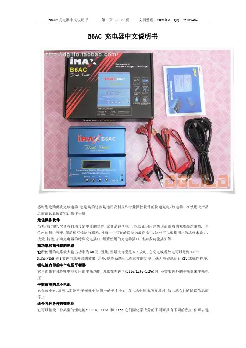
B6AC 充电器中文说明书感谢您选购此款充放电器.您选购的这款是运用高科技和专业操控软件的快速充电/放电器. 在使用此产品之前请认真阅读完此操作手册.最佳操作软件当充/放电时,它具有自动设定电流的功能.尤其是锂电池,可以防止因用户失误而造成的充电爆炸事故. 单位内的每个程序,都是相互控制与联系,使每一个可能的误差为最高安全.这些可以根据用户的选择来设定.接受,转接,启动充电器的特殊充电插口.频繁使用的充电器插口,比如多功能插头等.高功率和高性能的电路它所使用的电路最大输出功率为50瓦.因此,当最大电流是5.0安时,它充电或者放电可以达到15个NiCd/NiMH和6节锂电池并联的效果.此外,制冷系统可以在这样的功率下毫无障碍地运行CPU或操作程序. 锂电池内部的单个电压平衡器它里面带有独特锂电池专用的平衡功能.因此在充锂电(Lilo/LiPo/LiFe)时,不需要额外的平衡器来平衡电压.平衡放电的单个电池它在放电时,还可以监测和平衡锂电池组中的单个电池.当电池电压出现异常时,放电就会伴随错误信息而停止.适合各种各样的锂电池它可以接受三种类型的锂电池- Lilo, LiPo 和 LiFe.它们因化学成分的不同而具有不同的特点.你可以选择他们中任一一种来使用,根据它们的规格,参照”警告和安全说明书”.锂电池快速和存储模式你可以充电锂电池作特殊用途。
快速充电减少了锂电池的充电时间,而存储模式也使得锂电池的额定电压可以长时间的储存.最大化安全Delta-peak sensitivity:一种自动充电电流关闭程序,其工作原理是在电池电压上升至最高点而开始回降时,将充电电流关闭完成充电.(镍镉/镍氢)自动充电电流限制:在自动电流模式下充镍镉或镍氢电池,你可以设置充电电流的上限以避免高充电电流.在’AUTO’模式下,在充低阻碍,小容量的镍氢电池时非常有用.容量限制:充电容量以充电电流×充电时间来计算.在设定了最高充电值的情况下,当充电容量超过了最高限额时,程序将强制结束充电.温度限制:充电时,电池由于内部发生化学反应,温度也将相应增高.如果对充电器设定温度限制,在温度到达最高限额时,程序将强制结束充电.充电时间限制:对充电时间进行限制也可以防止任何可能的错误.输入电流检测器:为保护蓄电池在电流输入时不受损坏,通常可以对其电压进行检测.当电压下降至最低额时,程序将自动关闭充电电流.自动制冷风扇:只有在单个电池的内部温度升高时,电子制冷风扇才自动运转.资料存储/下载为方便用户,它最多可以存储5个数据不同的电池.你可以建立包含了程序设置的数据来持续不断的充电或是放电.在你需要的任意时候都可以叫出这些数据,并且这个过程在没有设定程序时执行.循环充电或者放电持续不断的运转1-5周期使电池得以更新和平衡.充电器外观警告和安全提示○任何情况都不要在无人看管的情况下充电.如果有故障出现,请立即结束程序,再查阅程序说明书.○不要放在有灰尘,潮湿,太阳直射或振动的地方,不要摔它.○进入电源只允许10-18DC电源.○充电器和电池在充电或放电时应放置在强抵抗,防易燃和抗导体的表面上.切勿放在汽车坐垫上,地毯上或类似物体上.确保所有易然易爆物品远离操纵区域.○充电器的冷却口不能被覆盖或关闭,以便提供良好的通风.确保准确地掌握要充电和放电的电池性能.如果程序设置错误可能损坏电池.尤其是锂电池,可能会导致火灾或充电过度导致爆炸.NiCd/NiMH 电压等级: 1.2v/cell允许快速充电电流: 1C~2C依赖于电池的运转.放电电压切断级别:0.85v /cell(镍镉电池), 1.0v/cell (镍氢电池)Lilo 电压等级:3.6V/c最大充电电压: 4.1V/cell允许快速充电电流: 1C或更少最小放电电压切断级别:2.5V/cell或更高○为避免充电导线之间发生短路,应先将充电导线与充电器连接, 然后再连接电池,拆开线路时,步骤相反. -你必须注意核实锂电池组的容量和电压.它可能是串,并联混合组成.并联时,电池组的容量是每个电池的容量乘以电池的个数,而电池组的电压不变. 在充电过程中,这种电压不平衡引起火灾或爆炸,我们建议你串联锂电池组.○放电放电的典型目的是确定电池剩余的容量或是降低电池的电压来界定级别.当你给电池放电时,必须和充电时一样注意放电过程.为了避免电池放电过度,一定要正确设定额定放电电压.锂电池不能低于最低电压,因为这样会导致容量的快速损失或者完全失败.一般来说,不需要给锂电池放电.-据说一些充电电池有记忆效应。

For Safety When Servicing or Maintaining Machine• Stop on level surface.• Disconnect the power to the machine by pulling the red Battery Connector located under the recovery tank near the batteries.• Avoid moving parts. Do not wear loose jackets, shirts, or sleeves when working on machine.• Avoid contact with battery acid. Battery acid can cause burns. When working on or around batteries, wear protective clothing and safety glasses. Remove metal jewelry. Do not lay tools or metal objects on top of batteries.• Do not clean machine with a pressure washer.• Authorized personnel must perform repairs and maintenance. Use Minuteman supplied replacement parts.Assembly Group Description Page 99706111BT10Chassis Assembly I1 99706111BT20Chassis Assembly II2 99706111BT30Chassis Assembly III3Water Feed System Subassembly4Lift Pedal Subassembly5Brush Pressure Adjustment Subassembly6Squeegee Connection Subassembly I7Squeegee Connection Subassembly II8 99706111BT40Battery Tray Assembly9 99706111BT50Solution Tank Assembly10Recovery Tank Drain Hose Subassembly11 99706111BT60Recovery Tank Assembly12 99706111BT70Vacuum Motor Assembly13 99706111BT80Squeegee Lift Handle Assembly14 99706111BT100Squeegee Assembly I15 99706111BT110Squeegee Assembly II16 99706111BT120Control Panel Assembly17Console Subassembly18 99706111BT130Electrical Assembly I19Retainer Subassembly20 99706111BT140Electrical Assembly II21 99706111BT160Battery Charger Assembly22 99706111BT170Deck Cover Assembly23 99706111BT180Solution Control Assembly24 99706111BT190Machine Labels25 99706111BT200Disc Scrub Deck Assembly I26 99706111BT210Disc Scrub Deck Assembly II27Bill of Material - 99706111BT10Item Spare part number Mat. No.Qty.Description 101078440905133671Grommet 203006710961079581Chassis 300053750123100417Washer 4000530801103819714Hexagon screw 501077760905031601Retainer 600042900123320293Washer 700053080110381976Hexagon screw 801077700904731581Bushing 900051510120400512Hexagon nut 1001077820905132431Bushing 1101072520111771791Lens flange screw 1201077740904952681Sheet metal 13000479901251508610Disk wheel 1400053020110380982Hexagon screw 1501077780905083911Bushing 1601078460961173871Sheet metal 1700053730123100334Washer 1800051520120400442Hexagon nut 1900022180110390882Hex.bolt 2000553740123101322Washer21Not Available905287871Retainer 2200975510903060021Micro switch 2301074840904714831Thread base plate 2400053010110380722Hex.bolt2501143190175260702Cable clipBill of Material - 99706111BT20Item Spare part number Mat. No.Qty.Description 101031540155920582Protection cap 200051490120400772Hexagon nut 300053770123100662Washer 400959310117170228Hex.bolt 501078010905101162Hub 600105350126101192Retaining ring7Not Available110382472Hex.bolt 8000537501231004110Washer 900053110110382542Hexagon screw 1001078020904816644Block11Not Available110382964Hex.bolt 1201078030961118691Lever 1300553580132801362Cotter pin 1400053770123100664Washer 1501077510148954784Slide bearing bush 1601078040133288512Bolt 1700053140110322734Hex.bolt 1801078480905120622Bearing AMER 1901079400905316091Traction drive20XXXXXXXX905233092WheelBill of Material - 99706111BT30Item Spare part number Mat. No.Qty.Description101015350175331592Hose clamp299706111BT311Water feed system, DO NOT ORDER, ITEM HAS SUBMODULES3Not Available125150861Washer400053080110381972Hexagon screw500053730123100332Washer600053010110380722Hex.bolt700042900123320292Washer899706111BT321Lifting pedal, DO NOT ORDER, ITEM HAS SUBMODULES999706111BT331Brush pression adjustment, DO NOT ORDER, ITEM HAS SUBMODULES 1001077790905090271Pipe1100053790123100821Washer1201077800905095221Bushing1301078140112256201Countersunk screw1401078150905233331Tension spring1500735690115181801Eye bolt1600053350120220591Hexagon nut1701077830905135731Pivot1800051510120400511Hexagon nut1999706111BT341Squeegee connection, DO NOT ORDER, ITEM HAS SUBMODULES 2001077840905151312Steering roller2100053750123100412WasherWater Feed System SubassemblyBill of Material - 99706111BT31Item Spare part number Mat. No.Qty.Description 10020017025842055560mm PVC hose 201015350175331596Hose clamp 300976140903106651Screwing in connecting piece 401071000904355951Electrovalve5Not Available905138961Sheet metal 600053710123100174Washer 700058580110389652Hex.bolt 800020020901749703Angle socket 90020017025842055540mm PVC hose 100020017025842055280mm PVC hose11Not Available905215761Ball valve12Not Available905073441Sheet metal 1300053790123100821Washer 1401077630905176571Screw 150020017025842055340mm PVC hose 1601077170905226401Water filter 1701079170010791701filter cartridge18Not Available20925000A1Filter cover 1900133830120400282Hex. Nut 2001078510961150351Sheet metalLift Pedal SubassemblyBill of Material - 99706111BT32Item Spare part number Mat. No.Qty.Description 1Contact Minuteman961173791Lifting Pedal 200053760123100582Washer 301077930961118771Rod 400551410132801101Cotter pin 500053360120220671Hexagon nut 600925430160550631Fork yoke 700925420133900421BoltBill of Material - 99706111BT33Spare part number Mat. No.Qty.Description00151440160550891Fork yoke00151400133900591Bolt01078500961115051Sheet metal00053360120220671Hexagon nutNot Available123320371Washer01031550110397161Hexagon screw01077770905042421Tension spring00706170115180161Eye bolt00053350120220591Hexagon nutSqueegee Connection Subassembly IBill of Material - 99706111BT34-1Item Spare part number Mat. No.Qty.Description 101130940116205641Cup head square neck bolt 2Not Available905217901Sheet metal 301077510148954782Slide bearing bush4Not Available902047021Pipe 501078230148954602Slide bearing bush 600054860132800781Cotter pin 700053750123100415Washer 801079280905347101Round part9Not Available133289351Bolt 1001079290961175691Sheet metal 1100042900123320291Washer 1200051510120400513Hexagon nut 1300053100110382472Hexagon screw 1401077700904731582Bushing 1501077980961123701Linkage 1600161240255820241Edge protectionChassis Assembly IIISqueegee Connection Subassembly IIBill of Material - 99706131BT34-2Item Spare part number Mat. No.Qty.Description 100054860132800781Cotter pin 200053750123100411Washer 301078230148954602Slide bearing bush 4Not Available133289351Bolt 501079320904958051Draft link 601077680904676861Bolt 701079330961102421Sheet metal 800046500120120192Hex. Nut 900051520120400442Hexagon nut 1000053730123100334Washer 1101078120905032511Hose support 1200053020110380982Hexagon screw 1301077850905151491Threaded pin 1400042900123320291Washer 1500051510120400511Knurled nut 1600054020121580281Wing nut 1700053330120220421Hex.nutBill of Material - 99706131BT40Item Spare part number Mat. No.Qty.Description1Not Available961176431Battery TrayBill of Material - 99706111BT50Item Spare part number Mat. No.Qty.Description101078100961140611Fresh water cap201078110904969102Hinge300042900123320294Washer400053080110381974Hexagon screw501072520111771794Lens flange screw601078120905032511Hose support701077910961095411Hose801161690175332901Clamp900020020901749701Angle socket1000057720152861491O-ring oil resistant1101078130961177341Solution tank1299706131BT50-11Foul water hose cpl., DO NOT ORDER - ITEM HAS SUBMODULES 1301077860905175741Hook1400751160175330431Hose clampRecovery Tank Drain Hose SubassemblyBill of Material - 99706111BT50-1Item Spare part number Mat. No.Qty.Description 100906110903045281Cover 200906100111753952Fillister-head screw 301077960970900961Foul water hose4Not Available172648881Decal Foul Water 501079300152820721O-RingBill of Material - 99706111BT60Item Spare part number Mat. No.Qty.Description 101077990970929511Cover 200855560111320654Cylinder head screw 300053730123100334Washer 401071770255105121Sealing profile 501078160117091514Screw 601078250970938431Filter unit 701079410961177261Recovery tank 800042900123320294Washer 900053080110381974Hexagon screw 1001077920961113491Suction hose 1101078120905032511Hose support1201072520111771792Lens flange screwBill of Material - 99706111BT70Item Spare part number Mat. No.Qty.Description1Not Available905239451Insulating mat 201077900905197371Hose 300732130175330271Hose clamp 401078180905036571Connection 500051520120400443Hexagon nut 600053730123100338Washer 701079350970962001Suction motor 8Not Available4Carbon brush 901078190905184573Buffer 1000025260110380563Hexagon screw 1400121150901148101Cable tie 1500967760901566884Cable tie 1600042900123320293Washer 1700053080110381973Hexagon screw 1800104500110380642Hexagon screw 19Not Available905196531Cover 70771/01 20Not Available905197451Insulating mat21Not Available961143011Sheet metalSqueegee Lift Handle AssemblyBill of Material - 99706111BT80Item Spare part number Mat. No.Qty.Description 100705560171430251Handle2Not Available961178251Lever 300051520120400441Hexagon nut 400135120123320111Washer 501071440148952882Plain bearing bush 6Not Available961108041Support plate7Not Available961107051Shaft with cam 801074840904714831Thread base plate 900975510903060021Micro switch 1000747400123321102Washer 1100022180110390882Hex.bolt 1200009000970923401Lifting suction unit 1301072520111771794Lens flange screwBill of Material - 99706111BT100Item Spare part number Mat. No.Qty.Description 101077660961134101Rear tension band 201077480904941391Sealing strip 301077940961132791Suction unit 401077470904935601Slot strip 501077650961134021Front tension band 601077590905145062Bushing 701077500115183131Eye bolt 801017660120402832Hex. Nut 901077580905357581Lever 1001079890110397652Hexagon screw 1100902250120224301Hex. Nut 1201078090905136311Pressure piece 1301077640961133031Front tension band 1401077670961134281Rear tension band1500009010970574591Lock suction unitBill of Material - 99706111BT110Item Spare part number Mat. No.Qty.Description 101059530110395676Hexagon screw 200902280123321364Washer 300924810903366372Deflector roller 400879030901990192Pipe 501071740110396092Hex.bolt 600101550123102646Washer 701077810905130942Fixed castor 801079070970988422Fixed castor 901077610905149934Distance piece 1001077600905149362Distance piece 1100911270258421051Hose 1201077620905154611Bracket 1300972060125150942Disk wheel 1400866720171330262Star handle15010790809053111210SpacerControl Panel AssemblyBill of Material - 99706111BT120Item Spare part number Mat. No.Qty.Description101074320111771874Lens flange screw201079760904945011Handle bar399706111BT120.11Console, DO NOT ORDER - ITEM HAS SUBMODULES 401079770961175851Sheet metal501072520111771794Lens flange screw600874720123102724Washer700961490117090114Self tapping screw801079950970960691Bail system900051510120400512Hexagon nutControl Panel AssemblyConsole SubassemblyBill of Material - 99706111BT120-1Item Spare part number Mat. No.Qty.Description 100021710903234371Key switch 200745890007458901Set (2pc.) key3Not Available961134691Panel, complete 4Not Available904994921Console 501078860117021234Screw 601078930905111301Ribbon cable 701078950905181501Cable key switchBill of Material - 99706111BT130Item Spare part number Mat. No.Qty.Description101072520111771795Lens flange screw201078570905098031Sheet metal300161240255820241Edge protection499706131BT130-11Retainer cpl., DO NOT ORDER - ITEM HAS SUBMODULES 500153200123470271Washer600051520120400441Hexagon nut7Not Available1Sheet metal801078580905113381Sheet metal901082530111771613Lens flange screw1001073420175210481Clamp11Not Available905291651Clamping plate1201078260904993772Bushing1300042900123320292Washer1400053110110382542Hexagon screw1501078270961149961CoveringRetainer SubassemblyBill of Material - 99706111BT130-1Item Spare part number Mat. No.Qty.Description 100967760901566884Cable tie 200121150901148108Cable tie 301077880905176991Webbing 400053730123100332Washer 500053010110380722Hex.bolt 601078640961176681Retainer 70072109025583022120mm Edge protection 800051340120400362Hexagon nut 900053720123100254Washer 1000054410110380492Hex.bolt 1100707360903310261Solenoid 1200131610155920334Lens cap13Not Available155952591Cable sleeve 1401078240905100174Washer 1500747210155920412Lens cap 1600051520120400441Hexagon nut 1700135120123320111Washer 1801079140970573841Controller E24/E26 with Package 1900972420009724200Strip fuse 2000902440009024400Strip fuse 2200972430009724300Fuse 23007210902558302230mm Edge protectionBill of Material - 99706111BT140Item Spare part number Mat. No.Qty.Description 101078600905181191Covering 201072520111771797Lens flange screw 301078610905113461Sheet metal 401078280904657741Bag 500555520123320523Washer 601078290131651963Blind rivet 703006850970942471Wiring harness W1 8Not Available970942541Wiring harness W2 9Not Available970990891Wiring harness W3 10Not Available970990631Wiring harness W9 1103006880970956241Wiring harness W11 1203006890970943871Set of cables 1303006900970956571Set of cables battery 1401078620905121461Sheet metal 1500053730123100332Washer 1600051520120400442Hexagon nut 1700053290110381302Hexagon screw 18001211509011481012Cable tie 19009677609015668818Cable tie 2001078630905113201Sheet metal21Not Available970990481Wiring harness W11Battery Charger AssemblyBill of Material - 99706111BT160Item Spare part number Mat. No.Qty.Description 101079380905329871Power Cord 201017640111770602Lens flange screw 301074240904637461Cap 401079360905332661Cover 501079370961171971Battery Charger 601077870905176651Tension band 701078320905125753Hose 800121150901148108Cable tie 900967760901566881Cable tie 1003006770970943041Wire harness W6 1103006840970943461Wiring harness W8Bill of Material - 99706111BT170Item Spare part number Mat. No.Qty.Description 1Not Available961150841Cover compl. 2Not Available961186743Weight3Not Available905392552Threaded rod 4Not Available123320292Washer5Not Available120400512Hexagon nutBill of Material - 99706111BT180Spare part number Mat. No.Qty.Description905024361Lever111771792Lens flange screw905024441Sheet metal905026181Shaft905024281Connecting pieceMachine LabelsBill of Material - 99706111BT190Item Spare part number Mat. No.Qty.Description 101077440172672121Decal Details 201077450172672201Decal 4,5bar3Not Available172051212Decal E264Not Available172011451Decal MinutemanBill of Material - 99706111BT200Item Spare part number Mat. No.Qty.Description 101077180905074762Motor 201077230010772302Fitting key 301077240010772401Set (4pc.) Carbon brush 4Not Available905031781Brush deck housing 500512400903243692Carrier 600879170902095372Washer 700053090110382132Hexagon screw 8752375232Pad driver 900101550123102644Washer 1000053110110382548Hexagon screw 1101077750905002162Sheet metal 1201078330905002652Spray tube 1300180190258420142Hose 1400901310902751571T-reducer muff 1501078070905241744Protection cap 1600681500903643651Center-lock, lower part 1700961490117090116Self tapping screw 1800681490903643731Center-lock,upper part 1901077250010772501Spring 2001077210010772101Gear2101077220010772201CirclipBill of Material - 99706111BT210Item Spare part number Mat. No.Qty.Description 100053310110383464Hexagon screw2Not Available123100586Washer 301077510148954784Slide bearing bush 4Not Available905387521Bracket 500051500120400695Hexagon nut 601078000961123882Ejector 701078350905002322Bellow 801078340905002082Compression spring 901078360148954372Slide bearing bush 1000046280126400332Thrust washer 1100712300175285481Tension band 1200901390175285551Tension band lock 13Not Available905363761Sealing strip 1401078060905002241Deflector roller 1501077560905002731Retainer1601077570905078311ScrewMinuteman International Made Simple Commercial Limited WarrantyMinuteman International, Inc. warrants to the original purchaser/user that the product is free from defects in workmanship and materials under normal use. Minuteman will, at its option, repair or replace without charge, partsthat fail under normal use and service when operated and maintained in accordance with the applicable operation andinstruction manuals. All warranty claims must be submitted through and approved by factory authorized repairstations.This warranty does not apply to normal wear, or to items whose life is dependent on their use and care, such as belts,cords, switches, hoses, rubber parts, electrical motor components or adjustments. Parts not manufactured by Minuteman are covered by and subject to the warranties and/or guarantees of their manufacturers. Please contact Minuteman for procedures in warranty claims against these manufacturers.Special warning to purchaser -- Use of replacement filters and/or prefilters not manufactured by Minuteman or its designated licensees, will void all warranties expressed or implied. A potential health hazard exits without originalequipment replacement.All warranted items become the sole property of Minuteman or its original manufacturer, whichever the case may be.Minuteman disclaims any implied warranty, including the warranty of merchantability and the warranty of fitness for aparticular purpose. Minuteman assumes no responsibility for any special, incidental or consequential damages.This limited warranty is applicable only in the U.S.A. and Canada, and is extended only to the original user/purchaserof this product. Customers outside the U.S.A. and Canada should contact their local distributor for export warrantypolicies. Minuteman is not responsible for costs or repairs performed by persons other than those specificallyauthorized by Minuteman. This warranty does not apply to damage from transportation, alterations by unauthorizedpersons, misuse or abuse of the equipment, use of non-compatible chemicals, or damage to property, or loss ofincome due to malfunctions of the product.If a difficulty develops with this machine, you should contact the dealer from whom it was purchased.This warranty gives you specific legal rights, and you may have other rights which vary from state to state. Somestates do not allow the exclusion or limitation of special, incidental or consequential damages, or limitations on howlong an implied warranty lasts, so the above exclusions and limitations may not apply to you.Cord Electric Group………. Three years parts, two years labor, ninety days travel (Not to exceed two hours) Exceptions………. Port-A-Scrub, one year parts, six months laborMPV 13, one year partsMPV 14 and 18, two years parts, one year laborRapidAir blower, one year parts, one year laborExplosion-Proof Vacuum, one year parts, one year laborPneumatic Vacuums, three years parts, one year laborEX 12 and EX12H, one year parts, one year laborBattery Operated Group….. Three years parts, two years labor, ninety days travel(Not to exceed two hours)Exceptions……Sweepers, one year parts, one year labor, ninety days travel(Not to exceed two hours)Internal Combustion Group….One year parts, one year labor, ninety day travel(Not to exceed two hours)Replacement Parts……………..Ninety daysBatteries………………………….0-3 months replacement, 4-12 months pro-ratePolypropylene Plastic Tanks…Ten years, no additional laborA Member of the Hako Group988026Rev * 11-13-07。
**2002年3月修订(第6版)日本标准商品分类号**2001年8月修订8761320.5g 1g承认号21300AMY00330指定医药品,要指示医药品(1)Keiten®0.5g静注用药价收载1993年8月指定医药品,要指示医药品(1)Keiten®1.0g静注用药价收载1993年8月贮法:室温保存。
硫酸头孢匹罗再审查结果2000年12月使用期限:标识在盒上(2年)注意:参照<使用注意>项[禁忌(下列患者不要给药)]对本剂成分有休克史患者。
[原则上禁忌(下列患者原则上不要给药,特别情况下有必要给药时要慎重)] 对本剂成分或头孢菌烷类物质有过敏史患者。
组成、性状1、组成静脉注射用Keiten0.5g和1g是在1小瓶中分别含硫酸头孢匹罗0.5g和1g(效价)。
2、性状本剂为白色~微黄色结晶粉末,稍有特殊气味,本剂溶于注射用水、生理盐水功效、效果葡萄球菌、链球菌、粪肠球菌属、布兰汉氏球菌属、大肠菌属、克累白蓖属、肠杆菌属、沙雷菌属、变形菌属、摩根菌属、普罗威登斯菌属、假单孢菌、流感嗜血杆菌、不动杆菌属和拟杆菌属,对本剂敏感,出这些细菌引起的哪些感染症有效,如:●败血症、感染性心内膜炎●蜂窝组织炎、淋巴管(结)炎●肛门周围脓肠、外伤和手术创伤等(浅表性)二次感染●咽喉炎、急性支气管炎、扁桃体炎(扁桃周围炎、扁桃周围脓疡)慢性支气管炎、支气管扩张(感染时)、慢性呼吸道疾病二次感染、肺炎、肺脓疡、脓胸●肾盂肾炎、膀胱炎、前列腺炎●胆囊炎、胆管炎、肝腔炎●腹膜炎●骨盆腹膜炎、直肠子宫陷凹脓疡●子宫附件炎、子宫内感染、子宫旁结缔组织类、前庭大腺炎●脊髓膜炎用法、用量硫酸头孢匹罗通常成人一天1~2g(效价)分次静脉注射、难治或重症感染依照病情可增量到一天4g,分2~4次注射。
小儿硫酸头孢匹罗通常一天按60~80mg(效价)/kg给药,分3~4次静脉注射。
根据年龄和病情药理可适当增减。
机器人控制器 控制单元 RC700RC700-A驱动单元 RC700DURC700DU-A编程软件 EPSON RC+7.0机器人 G1 G3 G6 G10 G20 系列RS 系列C4 C8 C12 系列N2 N6 系列X5 系列机器人系统安全与设置(RC700/EPSON RC+7.0)Rev.24机器人系统安全与设置(RC700 / EPSON RC+ 7.0)Rev.24Copyright 2012-2020 SEIKO EPSON CORPORATION. All rights reserved. 安全与设置(RC700 / EPSON RC+ 7.0) Rev.24 i前言感谢您购买本公司的机器人系统。
本手册记载了正确使用示教器所需的事项。
使用系统之前,请阅读本手册与相关手册,正确地进行使用。
阅读之后,请妥善保管,以便随时取阅。
保修本机及其选装部件是经过本公司严格的质量控制、测试和检查,并在确认性能满足本公司标准之后出厂交付的。
在交付产品的保修期内,本公司仅对正常使用时发生的故障进行免费修理。
(有关保修期方面的信息,请与当地销售商联系。
)但在以下情况下,将对客户收取修理费用(即使发生在保修期内):1. 因不同于使用说明书内容的错误使用以及使用不当而导致的故障与损伤。
2. 客户擅自改造或拆卸造成的故障。
3. 因调整不当/擅自修理而导致的损坏。
4. 因地震、洪水等自然灾害导致的损坏警告、注意、使用:1. 如果机器人或相关设备的使用超出本手册所述的使用条件及产品规格,将导致保修无效。
2. 本公司对因未遵守本手册记载的“警告”与“注意”而导致的任何故障或事故,甚至是人身伤害或死亡均不承担任何责任,敬请谅解。
3. 本公司不可能完全预见危险与故障发生的所有状况,此可预见性存在局限性。
因此,本手册不能警告用户所有可能的危险。
ii 安全与设置(RC700 / EPSON RC+ 7.0) Rev.24商标Microsoft、Windows及Windows标识为美国Microsoft Corporation在美国及其它国家的注册商标或商标。
螺内酯片说明书精编W O R D版IBM system office room 【A0816H-A0912AAAHH-GX8Q8-GNTHHJ8】螺内酯片说明书【药品名称】通用名:螺内酯片曾用名:商品名:英文名:Spironolactone Tablets汉语拼音:Luoneizhi Pian本品主要成分及其化学名称为:主要成分:螺内酯化学名称:17β-羟基-3-氧-7α-(乙酰硫基)-17α-孕甾-4-烯-21-羧酸γ-内酯。
其结构式为:分子式:C24H32O4S分子量:416.57【性状】本品为白色片。
【药理毒理】本药结构与醛固酮相似,为醛固酮的竞争性抑制剂。
作用于远曲小管和集合管,阻断Na+-K+和Na+-H+交换,结果Na+、C1-和水排泄增多,K+、Mg2+和H+排泄减少,对Ca2+和P3-的作用不定。
由于本药仅作用于远曲小管和集合管,对肾小管其他各段无作用,故利尿作用较弱。
另外,本药对肾小管以外的醛固酮靶器官也有作用。
【药代动力学】本药口服吸收较好,生物利用度大于90%,血浆蛋白结合率在90%以上,进入体内后80%由肝脏迅速代谢为有活性的坎利酮(canrenone),口服1日左右有所差异,每日起效,2~3日达高峰,停药后作用仍可维持2~3日。
依服药方式不同T1/2服药1~2次时平均19小时(13~24小时),每日服药4次时缩短为12.5小时(9~16小时)。
无活性代谢产物从肾脏和胆道排泄,约有10%以原形从肾脏排泄。
【适应症】(1)水肿性疾病与其他利尿药合用,治疗充血性水肿、肝硬化腹水、肾性水肿等水肿性疾病,其目的在于纠正上述疾病时伴发的继发性醛固酮分泌增多,并对抗其他利尿药的排钾作用。
也用于特发性水肿的治疗。
(2)高血压作为治疗高血压的辅助药物。
(3)原发性醛固酮增多症螺内酯可用于此病的诊断和治疗。
(4)低钾血症的预防与噻嗪类利尿药合用,增强利尿效应和预防低钾血症。
【用法与用量】 1.成人①治疗水肿性疾病,每日40~120mg,分2~4次服用,至少连服5日。
第一部分化学品及企业标识化学品中文名:N6-苯甲酰基腺嘌呤化学品英文名:N-1H-Purin-6-yl-benzamideN6-BenzoyladenineCAS No.:4005-49-6分子式:C12H9N5O产品推荐及限制用途:工业及科研用途。
第二部分危险性概述紧急情况概述吞咽有害。
可能导致皮肤过敏反应。
GHS危险性类别急性经口毒性类别 4皮肤致敏物类别 1标签要素:象形图:警示词:警告危险性说明:H302 吞咽有害H317 可能导致皮肤过敏反应防范说明●预防措施:—— P264 作业后彻底清洗。
—— P270 使用本产品时不要进食、饮水或吸烟。
—— P261 避免吸入粉尘/烟/气体/烟雾/蒸气/喷雾。
—— P272 受沾染的工作服不得带出工作场地。
—— P280 戴防护手套/穿防护服/戴防护眼罩/戴防护面具。
●事故响应:—— P302+P352 如皮肤沾染:用水充分清洗。
—— P332+P313 如发生皮肤刺激:求医/就诊。
—— P362+P364 脱掉沾染的衣服,清洗后方可重新使用——P305+P351+P338 如进入眼睛:用水小心冲洗几分钟。
如戴隐形眼镜并可方便地取出,取出隐形眼镜。
继续冲洗。
—— P337+P313 如仍觉眼刺激:求医/就诊。
—— P304+P340 如误吸入:将人转移到空气新鲜处,保持呼吸舒适体位。
—— P312 如感觉不适,呼叫解毒中心/医生●安全储存:—— P403+P233 存放在通风良好的地方。
保持容器密闭。
—— P405 存放处须加锁。
●废弃处置:—— P501 按当地法规处置内装物/容器。
物理和化学危险:无资料。
健康危害:吞咽有害。
可能导致皮肤过敏反应。
环境危害:无资料。
第三部分成分/组成信息√物质混合物第四部分急救措施急救:吸入:如果吸入,请将患者移到新鲜空气处。
皮肤接触:脱去污染的衣着,用肥皂水和清水彻底冲洗皮肤。
如有不适感,就医。
眼晴接触:分开眼睑,用流动清水或生理盐水冲洗。
SPECIFICATION SHEETFactory Automation Specification Sheet | Page 1 of 2Flexion™ N6 6-Axis RobotThe compact 6-Axis robot with a longreach and revolutionary design.World’s first folding-arm design — built for optimum motion and workspaceefficiencyIdeal for confined spaces — perfect for load/unload applicationsUltra long reach in a compact design — strong footprint-to-reach ratioUnique tight-space motion capability — ensures the robot’s arm extremitiesavoid obstaclesOutstanding motion efficiency — arm design allows for fast cycle timesPowerful arm design — 1,000 mm reach, up to 6 kg payloadRemarkable speed and precision — powered by Epson’s proprietary ResidualVibration TechnologyFull-featured Epson RC+® Development Software — makes it simple to createpowerful solutionsIntegrated vision guidance option — designed specifically for robot guidance;easily automates simple applications when vision is requiredOther integrated options — fieldbus interface solutions; RC+ 7.0 API softwarefor open-platform functionality; teach pendants; and customizable GUIs/N6Specification Sheet | Page 2 of 2Specifications and terms are subject to change without notice. EPSON and Epson RC+ are registered trademarks,EPSON Exceed Your Vision is a registered logomark and Better Products for a Better Future and Flexion are trademarks of Seiko Epson Corporation. All other product and brand names are trademarks and/or registered trademarks of their respective companies. Epson disclaims any and all rights in these marks. Copyright 2018 Epson America, Inc. Com-SS-Oct-13 CPD-56177R1 8/18Epson America, Inc.3840 Kilroy Airport Way, Long Beach, CA 90806Epson Canada Limited 185 Renfrew Drive, Markham, Ontario L3R 6G3 www.epson.caSee the latest innovations from Epson ® Business Solutions at /forbusiness/N6Contact:Max. Motion RangeJoint #1 ±180 deg Joint #2 ±180 deg Joint #3 ±180 deg Joint #4 ±200 deg Joint #5 ±125 deg Joint #6±360 deg*************************.com Sales Inquiries (562) 290-5997*****************.comFlexion N6 6-Axis Robot Back Panel。