ats2825-USB解码耳放电路
- 格式:pdf
- 大小:89.35 KB
- 文档页数:7
简单6N9C无输出变压器的耳机放大器电路近年来,随着国家经济的发展,人民生活水平不断提高。
青睐耳机这种发烧器件的朋友越来越多,而且,好耳机也层出不穷,为广大发烧友带来了福音。
然而,好的耳机需要好的驱动。
购买或制作一台高素质的耳机放大器就成为必需。
虽然晶体管、场效应管具有较低的输出阻抗。
然而。
越来越多的朋友开始喜欢电子管的声音。
认为电子管的声音更好听。
实际上也确实如此。
同时。
发烧耳机的阻抗一般在30-600Ω之间,远高于音箱的4-16Ω,用电子管,特别是采用无输出变压器方式制作耳机放大器成为可能。
本文介绍用国产小功率五极管6N9C (6P9P) 制作White Cathode Follower(WCF)耳机放大器。
一、设计思想采用无变压器输出,非常有利于业余制作。
现在国产很多高素质的电子管耳机放大器,也采用无输出变压器,说明电容输出可以得到较好的效果。
实际上,使用电容交流输出,可以很容易做到很宽的频率响应,也有利于阻抗匹配。
虽然电子管的种类繁多,但能够用于驱动耳机、音质较好且成本低廉的电子管却不多,因为对于输出管而言,需要较低的内阻、较高的跨导和较大的屏流。
本机使用了一种命名为6N9C(6P9P)的小功率五极管,用4只这种管子组成WCF电路,用来驱动低阻耳机,30Ω的阻抗也没有任何问题。
五极管的特点是细腻圆润。
将五极管接成三极管后,线性更好,内阻大幅度下降,跨导没什么大的变化,虽然输出功率有所减小,但对于耳机来说,也已经足够了。
6P9P为宽频带五极管。
可以非常方便地获得较宽的频率响应。
末级工作状态为WCF,是一种推挽线路,和SRPP非常相像,但它没有电压增益,当屏极电阻优化为一个管子跨导的倒数的时候。
其输出阻抗基本为两倍跨导的倒数。
因此。
与SRPP和阴极输出器相比。
WCF可以获得更低的输出阻抗,这一点不仅有利于驱动低阻耳机,对于中高阻耳机来说,也能获得更好的低频效果。
同时,与阴极输出器相比。
WCF由于是推挽线路。
自制OTL(电子管)耳机放大器近期因工作需要购买了森海塞尔的一款HD600耳机做*,它的阻抗为300Ω,算是高阻耳机,用CD机的耳放输出接口推动它时,虽然声压也达到一定的水平,但由于驱动功率太小,开大音量时,失真较大,声音不耐听,发挥不了HD600的高音质特性,故决定自己制作一个耳机放大器。
过去几年里,自己也制作过几款不同的电子管放大器,单从听音感觉去比较,我认为电子管放大器的声音要比晶体管放大器更动听,因此耳机放大器也打算用电子管制作。
上网看了一些耳机发烧友的制作经验并研究了很多不同种类的电子管耳机放大器线路后,再考虑自己的电子管存货,我决定选用Morgan Jones(摩根·琼斯)设计的电子管耳机放大器。
电路原理该电路原理图见图1。
它是一个无输出变压器(OTL)电路,没有环路反馈,电路十分简洁,非常适合初级耳机发烧友仿制。
这个耳机放大器只用6N1一种型号的双三极电子管,左右双声道共用3枚6N1电子管,6N1有很好的参数曲线,社会库存量较大,而且售价不高,有利于降低成本。
虽然声音特色和特性会有所差异,但6N1原则上可与6N11(6922、6DJ8、ECC82、E88CC)兼容和互换,当然如果使用6N11,线路的相关元件和屏压要作相应改变,图2就是改用6N11电子管制作的该耳机放大器,供感兴趣的朋友参考。
在这里我采用的是北京电子管厂生产的6N1T(特级)电子管。
这个6N1 OTL放大器线路最大特点是采用不对称输出,它其实和前一段时间很流行的禾田茂氏放大器的线路有几分相似,它去掉了禾田茂氏放大器的线路输入级,信号经100k的音量控制电位器控制后输入V1的栅极,其屏阴输出使各种阻抗尤其是高阻抗耳机有较充裕的音量输出。
不过,6N1的OTL 输出在驱动低阻抗耳机的表现可能不如它驱动高阻抗耳机。
由于它的末级采用仿如SRPP般的不对称输出,需要较高电压的电源供电。
图3为电源部分。
在笔者的经验中,简单的线路要有良好的音效,电源部分要下很大的功夫。
胆机基因——凯音C6解码耳放开箱前两天收到了一台有意思的耳放,凯音C6 ,来自国产珠海斯巴克,斯巴克的凯音品牌已经有20年历史了,以生产高端HiFi胆机功放闻名国内外,这款C6属于凯音“真红系列”,这个系列不光有便携耳放,还有台式解码耳放。
C6我之说以说它有意思是因为它支持iPhone/ipad/itouch几乎是苹果家全系便携产品,而且是一台支持最新的iphone 5S /5c解码的产品。
先来看看参数:【D/A转换芯片】WM8741 【采样频率】44.1/48kHz@16bit模拟音频输入≤1000mV【最大输出功率】130mW+130mW (32Ω负载)【频率响应】20Hz-20kHz(±1dB)(AUDIO IN)【总谐波失真】≤0.05%(1kHz)【信噪比】≥98dB(A计权)【锂电池容量】2500mAh【续航时间】≥8小时(32Ω负载)【尺寸】60mm x 20mm x 130mm(宽/高/长)仍然是从包装盒开始,这台耳放的包装很朴素简单,显得很低调,手写字体的凯音标识是包装盒上最显眼的东西,国内有很多造传统的音频设备造的很不错的厂商,斯巴克、声雅、天逸等等,这些厂商能够开始关注台式HiFi/便携听音市场是一件很好的事情。
对于胆机,温暖细腻舒顺的音色是让人最印象深刻的,所以对于这款产品,我还是充满了期待,凯音在之前做了两台真空电子管的台式耳放,所以我很希望能在C6调音上厂商会吸收吸收胆机功放音色的特点。
开箱后就可以看到这个金属质感的家伙,这台耳放有黑色、红色、银色、枪色四个颜色,我还是选择了比较传统的黑色,整个外壳都是铝合金拉丝工艺,拿在手里并不重,大家会注意到C6的机身比较长,130mm,这个机身尺寸其实和iphone5修长的机身会很搭。
单从工艺上来说,凯音C6的制造工艺还是很精湛的,也比较带感,不过从产品工业设计上来说,设计语言还是比较传统,那种粗犷的音频设备味道。
可能和数码时代风格偏时尚的手机搭配起来略微有些相左。
ATS2825使用手册一、设备简介ATS2825是一款高效、可靠的自动测试系统,广泛应用于各种电子产品的测试和测量。
它集成了多种测试功能于一体,具有高精度、高可靠性、易操作等特点。
本手册将指导您如何正确使用ATS2825。
二、设备安装在安装ATS2825之前,请先阅读本手册并确保您已了解所有注意事项。
然后按照以下步骤进行安装:1.打开包装箱,检查设备组件是否齐全,是否有损坏。
2.根据提供的安装指南和图纸进行安装,确保将设备安装在稳定、平整的地面上。
3.连接电源和信号线,确保符合当地法规和标准。
4.进行初步测试,确保设备正常工作。
三、设备配置ATS2825的配置包括硬件和软件两部分。
请按照以下步骤进行配置:1.根据您的测试需求,选择合适的测试模块和附件,并进行连接。
2.安装随设备提供的软件,并进行必要的配置,如测试项目、测试参数等。
3.启动软件并连接ATS2825,确保软件能够控制设备进行测试。
四、设备操作ATS2825的操作主要包括软件操作和硬件操作两部分:1.软件操作:通过软件界面进行测试项目的选择、参数设置、数据采集和结果显示等操作。
2.硬件操作:根据需要连接被测件、设置测试模块、执行测试等操作。
五、设备维护为了保持ATS2825的性能和延长其使用寿命,应定期进行维护:1.清洁设备表面,保持整洁。
2.检查电源线和信号线是否连接牢固,是否有破损或腐蚀现象。
3.对测试模块进行检查和清洁,确保其正常工作。
4.对软件进行更新,以获得最新的功能和修复潜在的错误。
5.定期进行全面检查和维护,以确保设备的整体性能和可靠性。
六、常见问题与解决在遇到问题时,请参考本手册中的“常见问题与解决”部分,查找相应的问题描述和解决方案。
如果问题仍未解决,请联系制造商或专业技术人员寻求帮助。
七、技术支持与售后服务为了确保您能够充分利用ATS2825的功能并解决使用中遇到的问题,我们提供全面的技术支持和售后服务:1.技术支持:我们提供技术咨询、故障排除和技术培训等服务,以确保您正确使用设备并充分利用其功能。
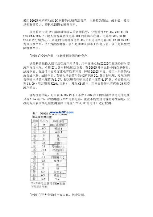
采用D2025双声道功放IC制作的电脑有源音箱,电路较为简洁,成本低,故市场拥有量较大,整机电路图如附图所示。
从电脑声卡或DVD播放机等输人的音频信号,分别通过VR1,C7,VR2,C6和VR3,C14,VR4,C12输人到音频功放电路IC1的⑩脚和⑦脚。
电路中VR2,C8和VR4,C巧分别为左、右声道的音调调节电路;C2,C10是自举电容:R2,C3和R3,C11为负反馈网络,C13为滤波电容。
表1是D2025参考工作电压值,以下是典型故障检修2例。
[故障1]交流声重,仅能听到微弱的伴音声。
试关断音频输人信号后交流声即消除,用干扰法点触D2025⑦脚或⑩脚时交流声再度出现,检测IC 1各引脚电压均正常。
查D2025外围元件中的自举电容、滤波电容、负反馈电容及交连电容均无异常。
怀疑D2025不良,换用一块新的功放集成电路,故障依旧。
在输人动态信号的状况下测IC1各引脚电压,发现②脚音频输出端的电压值为5.2V,较⑩脚音频输出端的电压值6.3V低。
检查输出电容C4,C9(用万用表RX10k挡测),发现C9漏电,用同容量新电容代换C9后交流声消失。
值得注意的是,万用表Rx10k以下(不含RxlOk挡)的低阻挡供电电池电压只有1:5V或3V,对检测耐压25V电解电容,往往不能发现电容的隐性漏电,应改用万用表的高电阻值测量挡(内置15V或9V的电池)进行检测。
[故障2]开大音量时声音失真、低音发闷。
放大音量,检测D2025各脚电压,发现电压均有较大幅度波动。
检查滤波电容量正常。
查D2025的额定工作电流为之200mA,而这款有源音箱的供电,之后调大音量试机,音质大为改善,低音明显厚实,再无失真、发闷现象。
对于47耳放的完美改进制作高保真耳机放大器之前一直折腾功放听桌面音箱,半年前忽然打算用用耳机了,于是入了森海的HD595。
虽然50欧的阻抗不算高,但是要发挥出设备的实力耳放还是少不了的。
所以,决定自己动手做一个耳放。
这期间参考了大量关于耳放的资料,最终决定以47耳放电路为基础并加以改进制作一个比较完美的耳机放大器。
便动手做了起来。
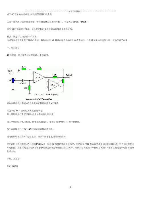
一、放大部分47耳放是一位外国人设计的电路,电路如图。
因为电路中有较多以47为参数的元件所以称作47耳放。
传说中的47耳放结构其实是很简单的,第一级运放进行负反馈控制放大倍数进行比例放大,第二个运放进行电压跟随,降低放大器内阻,增加了输出电流,并做声音修饰。
两个运放输出经过两个47欧匀流电阻输出致耳机。
因为反馈取样点在47电阻之后,所以不用考虑电阻带来的损耗。
曾经在网上看过很多47耳放的PCB设计,虽然47耳放的电路十分简单,但是很多PCB却存在着或多或少的布线问题,有些抗干扰能力不是很强,甚至在淘宝上看到很多看似很漂亮的板子却有很大的交流声。
所以自己决定做一个比较完美的47耳放以便把这个电路的能力发挥出来。
于是,开工了。
首先线路图电路没有添加音量电位器,只做了放大部分。
这样一来功能比较独立,方便以后的各种组合。
47原设计使用的运放是OPA2132,这个运放是FET输入型的,所以内阻极高。
而且在低电压下可以正常工作,失调电压与失调电流极小,算是比较高档的运放了。
当然OPA2132的价格也是很高档的。
我作为0收入人士必然不能把这种高档传承下去,于是我选用了这年头满大街都是的NE5532。
NE5532虽然指标相对于OPA2132较差,但是工作于+-15V时音色总体来说还是比较讨人喜欢的。
单片5532耗电相对较大,两片并联就更不用说了,双15V下耗电可想而知。
这就意味着这款耳放将要脱离便携式耳放的范畴转型向台式耳放了。
由于5532失调电压较高而且又是NPN管输入的,如果使用原设计必然会引来较大的输出中点漂移,经过测试最大有30多MV。

6SA7(6N5P)阴极输出耳放的制作在95年的audio&techniek杂志上看到了一篇Rudy Van Stratum先生发表的一个电子管的耳机放大器电路,不过,Stratum先生也没有实作过,仅仅是一个电路,这个电路引起了我的注意,因为我发现他具有以下特点:1。
电路简洁,两个声道一个只需要2只双三极管,这个是我见到最简单的耳机放大器电路。
2。
可以驱动低阻耳机。
3。
两级放大之间使用直接偶合电路。
4。
无大环路负反馈。
5。
单端甲类输出。
我按照这个电路实作了一台,经过这段时间的试听(超过三个月时间,使用CD、磁带等不同信号源)我可以告诉大家,这是一台非常好的耳机放大器。
经过我略微修正的电路如图1所示,它第一级使用双三极管ECC88中的一个作共阴极放大,第二级使用双三极管6AS7G中的一个作阴极输出,两级之间直接藕合,在原来电路图上我加了一个音量电位器和ECC88的栅漏电阻,输出电容也由100uF增加到200uF,增加电容容量的原因很简单,一个是我要使用低阻抗的32-60欧的耳机,另外我手中也恰好有这种电容,经过测试,使用60欧耳机,-3db的下降点在12Hz,使用32欧耳机,-3db的下降点在22Hz。
这台机器的外观处理很简单,我的第一台原型机使用了装饰用的宝丽板作机壳,我几乎是立刻就喜欢上了它,他的声音细节非常精确,可以听出更多的细节和空气感,本来阴极输出器有声音暗淡的名声,令人厌烦不敢恭维,但是这个电路改变了我的认识,呈现一种与之完全相反的并能紧紧抓住你注意力的声音,弱音之间的区别变得非常明显,举个例子,你可以听出不同大提琴之间音色的区别,我的晶体管耳机放大器与之比较,就显得声音发硬,呆滞,高频有毛刺感,结像力不足,我想这是因为这台电子管耳放电路简洁,并且没有大环路负反馈的结果,当然本机为单端输出,而那台晶体管机器电路为推挽也是原因之一。
通过一段时间的试听,我非常满意这种声音风格,最后我使用了一个4*8*1英寸的铝合金壳子作为我这台机器的机壳,制作我使用了搭棚焊接,没有使用商品机常见的PCB电路板形式,经过搭配使用森海塞尔HD465,HD580,AKG K240,松下EAH-S30试听,低阻抗耳机的表现要比高阻耳机好,说明本电路适合搭配低阻耳机使用。
JVC⾳响UX-H30电路原理图SERVICE MANUALCOPYRIGHT ? 2003 VICTOR COMPANY OF JAPAN, LIMITEDNo.MB0242003/8MICRO COMPONENT SYSTEMUX-H30TABLE OF CONTENTS1PRECAUTION. . . . . . . . . . . . . . . . . . . . . . . . . . . . . . . . . . . . . . . . . . . . . . . . . . . . . . . . . . . . . . . . . . . . . . . . . 1-32SPECIFIC SERVICE INSTRUCTIONS. . . . . . . . . . . . . . . . . . . . . . . . . . . . . . . . . . . . . . . . . . . . . . . . . . . . . . 1-63DISASSEMBLY . . . . . . . . . . . . . . . . . . . . . . . . . . . . . . . . . . . . . . . . . . . . . . . . . . . . . . . . . . . . . . . . . . . . . . . 1-74ADJUSTMENT . . . . . . . . . . . . . . . . . . . . . . . . . . . . . . . . . . . . . . . . . . . . . . . . . . . . . . . . . . . . . . . . . . . . . . . 1-175TROUBLESHOOTING . . . . . . . . . . . . . . . . . . . . . . . . . . . . . . . . . . . . . . . . . . . . . . . . . . . . . . . . . . . . . . . . . 1-21 SPECIFICATIONAmplifier Output Power20 W (10 W + 10 W) at 4 ? (10% THD)Audio input sensitivity/Impedance (at 1 kHz)AUX500 mV/48.75 k?Speakers/Impedance 4 ?Tuner FM tuning range87.50 MHz - 108.00 MHzAM tuning range AM 10 kHz intervals530 kHz - 1 710 kHzAM 9 kHz intervals531 kHz - 1 710 kHzCD player Dynamic range85 dBSignal-to-noise ratio90 dBWow and flutter ImmeasurableCassette deck Frequency response Normal (type I)50 Hz - 15 000 HzWow and flutter0.15% (WRMS)Speaker Speaker units Full range8.0 cm cone × 1Impedance 4 ?Dimensions (approx.)135 mm × 203 mm × 190 mm (W/H/D)Mass (approx.) 1.7 kg eachGeneral Power requirement AC IN110 V/ 127 V/ 230 V ,adjustable with the voltageselector,50 Hz/ 60 HzDC IN12 V, 4 APower consumption35 W (at operation)3.0 W (on standby)Dimensions (approx.)412 mm × 208 mm × 275 mm (W/H/D)Mass (approx.) 6.5 kg1-2 (No.MB024)SECTION 1PRECAUTION1.1Safety Precautions(1)This design of this product contains special hardware andmany circuits and components specially for safety purpos-es. For continued protection, no changes should be madeto the original design unless authorized in writing by themanufacturer. Replacement parts must be identical tothose used in the original circuits. Services should be per-formed by qualified personnel only.(2)Alterations of the design or circuitry of the product shouldnot be made. Any design alterations of the product should not be made. Any design alterations or additions will void the manufacturers warranty and will further relieve the manufacture of responsibility for personal injury or property damage resulting therefrom.(3)Many electrical and mechanical parts in the products havespecial safety-related characteristics. These characteris-tics are often not evident from visual inspection nor can the protection afforded by them necessarily be obtained by us-ing replacement components rated for higher voltage, watt-age, etc. Replacement parts which have these special safety characteristics are identified in the Parts List of Ser-vice Manual. Electrical components having such features are identified by shading on the schematics and by ( ) on the Parts List in the Service Manual. The use of a substitute replacement which does not have the same safety charac-teristics as the recommended replacement parts shown in the Parts List of Service Manual may create shock, fire, or other hazards.(4)The leads in the products are routed and dressed with ties,clamps, tubings, barriers and the like to be separated from live parts, high temperature parts, moving parts and/or sharp edges for the prevention of electric shock and fire hazard. When service is required, the original lead routing and dress should be observed, and it should be confirmed that they have been returned to normal, after reassem-bling.(5)Leakage shock hazard testingAfter reassembling the product, always perform an isola-tion check on the exposed metal parts of the product (an-tenna terminals, knobs, metal cabinet, screw heads, headphone jack, control shafts, etc.) to be sure the product is safe to operate without danger of electrical shock.Do not use a line isolation transformer during this check.Plug the AC line cord directly into the AC outlet. Using a "Leakage Current Tester", measure the leakage current from each exposed metal parts of the cabinet, particular-ly any exposed metal part having a return path to the chassis, to a known good earth ground. Any leakage cur-rent must not exceed 0.5mA AC (r.m.s.).Alternate check methodPlug the AC line cord directly into the AC outlet. Use an AC voltmeter having, 1,000?per volt or more sensitivity in the following manner. Connect a 1,500? 10W resistor paralleled by a 0.15µF AC-type capacitor between an ex-posed metal part and a known good earth ground. Measure the AC voltage across the resistor with the AC voltmeter.Move the resistor connection to each exposed metalpart, particularly any exposed metal part having a returnpath to the chassis, and measure the AC voltage acrossthe resistor. Now, reverse the plug in the AC outlet andrepeat each measurement. Voltage measured any mustnot exceed 0.75 V AC (r.m.s.). This corresponds to 0.5mA AC (r.m.s.).1.2Warning(1)This equipment has been designed and manufactured tomeet international safety standards.(2)It is the legal responsibility of the repairer to ensure thatthese safety standards are maintained.(3)Repairs must be made in accordance with the relevantsafety standards.(4)It is essential that safety critical components are replacedby approved parts.(5)If mains voltage selector is provided, check setting for localvoltage.1.3CautionBurrs formed during molding may be left over on some parts of the chassis.Therefore, pay attention to such burrs in the case of pre-forming repair of this system.1.4Critical parts for safetyIn regard with component parts appearing on the silk-screen printed side (parts side) of the PWB diagrams, the parts that are printed over with black such as the resistor ( ), diode ( ) and ICP ( ) or identified by the " " mark nearby are critical for safety. When replacing them, be sure to use the parts of the same type and rating as specified by the manufacturer.(This regulation dose not Except the J and C version)(No.MB024)1-31.5Preventing static electricityElectrostatic discharge (ESD), which occurs when static electricity stored in the body, fabric, etc. is discharged, can destroy the laser diode in the traverse unit (optical pickup). Take care to prevent this when performing repairs.1.5.1 Grounding to prevent damage by static electricityStatic electricity in the work area can destroy the optical pickup (laser diode) in devices such as CD players.Be careful to use proper grounding in the area where repairs are being performed.(1)Ground the workbenchGround the workbench by laying conductive material (such as a conductive sheet) or an iron plate over it before placing the traverse unit (optical pickup) on it.(2)Ground yourselfUse an anti-static wrist strap to release any static electricity built up in your body.(3)In order to maintain quality during transport and before installation, both sides of the laser diode on the replacement optical pickup are shorted. After replacement, return the shorted parts to their original condition.(Refer to the text.)Do not use a tester to check the condition of the laser diode in the optical pickup. The tester's internal power source can easilydestroy the laser diode.1.6Handling the traverse unit (optical pickup)(1) Do not subject the traverse unit (optical pickup) to strong shocks, as it is a sensitive, complex unit.(2) Cut off the shorted part of the flexible cable using nippers, etc. after replacing the optical pickup. For specific details, refer to thereplacement procedure in the text. Remove the anti-static pin when replacing the traverse unit. Be careful not to take too longa time when attaching it to the connector.(3) Handle the flexible cable carefully as it may break when subjected to strong force.(4)I t is not possible to adjust the semi-fixed resistor that adjusts the laser power. Do not turn it.1.7Attention when traverse unit is decomposed*Please refer to "Disassembly method" in the text for the CD pickup unit.Apply solder to the short land sections before the flexible wire is disconnected from the connector CN601 on the CD servo board.(If the flexible wire is disconnected without applying solder, the CD pickup may be destroyed by static electricity.)In the assembly, be sure to remove solder from the short land sections after connecting the flexible wire.1-4 (No.MB024)1.8Important for laser products(No.MB024)1-5SECTION 2SPECIFIC SERVICE INSTRUCTIONSThis service manual does not describe SPECIFIC SERVICE INSTRUCTIONS. 1-6 (No.MB024) SECTION 3DISASSEMBLY 3.1Main body3.1.1Removing the rear panel(See Fig.1,2)(1)From behind the body, remove the nine screws A attach-ing the rear panel.(2)Turing the body upside down, remove the two screws B at-taching the rear panel, and remove.3.1.2Removning the side panel (L) and (R)(See Fig.2~5)Prior to performing the following procedure, remove the rear panel.(1)Turning the body upside down, remove the two screws C attaching the front panel assembly.(2)Turning the body initial position, open the CD door while pressing the upper OPEN button.(3)Moving the side panel (L) in the arrow direction, remove the panel from the left side of the body.(4)Moving the side panel (R) in the arrow direction, removethe panel from the right side of the body.(No.MB024)1-73.1.3Removing the CD player assemblyPrior to performing the following procedure, remove the rear panel and the left and right side panels.(1)Disconnect the card wires from the two connectors CN603and CN604 on the CD servo control board.(2)Remove the two screws D attaching the front panel as-sembly on the both sides.(3)Release the two joints a on the both sides of the front pan-el assembly.(4)Move the CD player assembly in the direction of the arrow.1-8 (No.MB024)3.1.4Removing the power amplifier board and heat sink(See Fig.8~10)Prior to performing the following procedure, remove the rear panel, the left and right side panels, and the CD player assem-bly.(1)Remove the five screws E and F attaching the heat sink.(2)Disconnect the wire from connector CN901 on the powersupply board.(3)Disconnect the card wire from connector CN305 on thepower amplifier board.(4)Remove the screw G attaching the power amplifier board.(5)Disconnect the connector CN301 on the power amplifierboard, and release the two joints b .REFERENCE:Remove the screw F , then power amplifier board can be re-moved without removing heat sink.3.1.5Removing the tuner board(See Fig.11)Prior to performing the following procedure, remove the rearpanel, the left and right side panels, and the CD player assem-bly.(1)Remove the screw H attaching the tuner board from theright side of the body.(2)Disconnect the card wire from the connector CN1 on thetuner board.(3)Release the joint c , and remove the tuner board backward.(No.MB024)1-93.1.6Removing the front panel assembly(See Fig.12,13)Prior to performing the following procedure, remove the rear Array panel the left and right side panels, the CD player assembly,the power amplifier board.(1)Disconnect the card wire from the connector CN714 on theLCD system CPU board.(2)Release the joint d on the bottom of the front panel as-sembly using a screwdriver, and remove the front panel as-sembly toward the front.3.1.7Remove the power transformer and power supply board(See Fig.14,15)Prior to performing the following procedure, remove the rear Array panel, the left and right side panels, the CD player assembly,the power amplifier board and the tuner board.(1)Remove the screw I attaching the jack holder and releasejoint e , and then remove jack holder.(2)Remove the four screws J attaching the power transformerand power supply board.1-10 (No.MB024)3.1.8Remove the cassette mechanism assemblyPrior to performing the following procedure, remove the front panel assembly.(1)Disconnect the card wire from the connector CN713 on the LCD system CPU board.(2)Remove the four screws K and L attaching the cassette mechanism assembly, and remove.(No.MB024)1-113.1.9Remove the LCD system CPU board(1)Disconnect the wire from the connector CN716 on the LCDsystem CPU board.(2)Release the two joints f and pull out the LCD system CPUboard.3.1.10Removing the operating switch board(See Fig.19,20)Prior to performing the following procedure, remove the front Array panel assembly, the cassette mechanism assembly and theLCD system CPU board.(1)Remove the two screws M attaching the operating switchbutton.(2)Remove the two screws N attaching the operating switchboard, and remove.1-12 (No.MB024)3.2Cassette mechanism assembly3.2.1Removing the Play/Record & Clear head(1)While moving the trigger arm on the right side of the head mount in the direction of the arrow, turn the flywheel R counterclockwise until the head mount comes ahead and clicks.(2)The head turns counterclockwise as you turn the flywheel R counterclockwise (See Fig.2 and 3).(3)Disconnect the flexible wire from connector CN31 on the head amplifier & mechanism control board.(4)Remove the spring from the back of the head.(5)Loosen the azimuth screw for reversing attaching the head.(6)Remove the head on the front side of the head mount.(No.MB024)1-133.2.2Removing the head amplifier & mechanism control board(See Fig.4)(1)Turn over the cassette mechanism assembly and removethe three screws A attaching the head amplifier & mecha-nism control board.(2)Disconnect the flexible wire from connector CN31 on thehead amplifier & mechanism control board.(3)Disconnect connector CN32 of the head amplifier & mech-anism control board from connector CN1 on the reel pulse board.REFERENCE: If necessary, unsolder the 4-pin wire soldered to the main motor.3.2.3Removing the main motor(See Fig.4~7)(1)Remove the two screws B .(2)Half raise the motor and remove the capstan belt from themotor pulley.ATTENTION:Be careful to keep the capstan belt from grease. When reas-sembling, refer to Fig.6 and 7 for attaching the capstan belt.1-14 (No.MB024)3.2.4Removing the flywheelPrior to performing the following procedure, remove the head amplifier & mechanism control board and the main motor as-sembly.(1)From the front side of the cassette mechanism, remove the slit washers attaching the capstan shaft L and R. Pull outthe flywheels backward.3.2.5Removing the reel pulse board and solenoid(See Fig.10)Prior to performing the following procedure, remove the head amplifier & mechanism control board.(1)Remove the screw C.(2)Release the tab a, b, c, d and e retaining the reel pulse board.(3)Release the tab f and g attaching the solenoid on the reel pulse board.(4)The reel pulse board and the solenoid come off.(No.MB024)1-153.2.6Reattaching the Play/ Record & Clear head(See Fig.11~13)(1)Reattaching the head mount assembly.a)Change front of the direction cover of the headmount assembly to the left (Turn the head forward).b)Fit the bosses O', P', Q', U' and V' on the head mountassembly to the holes P and V, the slots O, U and Qof the mechanism sub assembly (See Fig.11 to 13).CAUTION:To remove the head mount assembly, turn the directioncover to the left to disengage the gear. If the gear can notbe disengaged easily, push up the boss Q' slightly andraise the rear side of the head mounts slightly to returnthe direction lever to the reversing side.(2)Tighten the azimuth screw for reversing.(3)Reattach the spring from the back of the Play/ Record &Clear head.(4)Connect the flexible wire to connector CN31 on the headamplifier & mechanism control board.1-16 (No.MB024)SECTION 4ADJUSTMENT 4.1Measurement Instruments Required for Adjustment(1)Low frequency oscillatorThis oscillator should have a capacity to output 0dBs to 600? at an oscillation frequency of 50Hz-20kHz.(2)Attenuator impedance : 600?(3)Electronic voltmeter(4)Distortion meter(5)Frequency counter(6)Wow & flutter meter(7)Test tapeVT703L : Head azimuthVT712 : Tape speed and running unevenness (3kHz)VT724 : Reference level (1kHz)(8)Blank tapeTYPE l : AC-225TYPE ll : AC-514(9)Torque gauge : For play and back tensionFWD(TW2111A), REV(TW2121a) and FF/REW(TW2231A) (10)Test disc: CTS-1000 4.2Measurement conditons4.2.1Radio Input signal 4.2.2Tuner section4.2.3Standard measurement position of volume Precautions for measurement (1)Apply 30pF and 33k? to the IF sweeper output side and0.082µ F and 100k? in series to the sweeper input side.(2)The IF sweeper output level should be made as low aspossible within the adjustable range.(3)Since the IF sweeper is a fixed device, there is no needto adjust this sweeper.(4)Since a ceramic oscillator is used, there is no need toperform any MIX adjustment.(5)Since a fixed coil is used, there is no need to adjust theFM tracking.(6)The input and output earth systems are separated. Incase of simultaneously measuring the voltage in both ofthe input and output systems with an electronic voltmeterfor two channels, therefore, the earth should be connect-ed particularly carefully.(7)In the case of BTL connection amp., the minus terminalof speaker is not for earthing. Therefore, be sure not toconnect any other earth terminal to this terminal. Thissystem is of an BTL system.(8)For connecting a dummy resistor when measuring theoutput, use the wire with a greater code size.(9)Whenever any mixed tape is used, use the band pass fil-ter (DV-12).Power supply voltage AC 110V/127V/230Vadjustable with the voltage selector,50Hz/60HzReference output Speaker : 0.775V/4?Headphone : 0.077V/32?Reference frequency and input level1kHz, AUX : -8dBs Measurement output terminal at Speaker J3002 Load resistance4? AM frequency400HzAM modulation30%FM frequency400HzFM frequency deviation22.5kHz Voltage applied to tuner+B : DC5.7VVT : DC 12VReference measurement output26.1mV(0.28V)/3?Input positions AM : Standard loop antennaFM : TP1 (hot) and TP2 (GND)Function switch to TapeBeat cut switch to CutSuper Bass/Active hyper Bass to OFFBass Treble to Center Adjustment of main volume to reference output VOL : 0.775V(No.MB024)1-174.3Cassette mechanism adjustment1-18 (No.MB024)4.3.1Mechanism sectionItem Condition Measurement method Ref. value Adjustment position Head azimuth Test tape:VT703L (8kHz)Output terminal:Speaker out (1)Playback the test tape VT703L (8kHz).(2)Adjust to maximum output level by azi-muth adjustment screw for forward sideand reverse side.(3)This adjustment is adjust by adjustmentscrew of forward side and adjustmentscrew of reverse side.Maximum output Only adjustat changedheadTape speed Test tap:VT712 (3kHz)Output terminal:Speaker out or Headphone out Playback the test tape VT712 (3kHz) at end of forward side,adjust to 2,940~3,90Hz indicationof frequency counter by VR37.2,940 ~ 3,090Hz VR37Item Condition Measurement method Ref. value Adjustment positionTape speed diviation at FWD/ REV Test tape: VT712 (3kHz)Output terminal:Speaker out or Headphone outPlayback the test tape VT712 (3kHz) at end offorward and reverse, tape speed deviationshould be less than 6.0Hz.Leass than6.0HzVR31Wow & Flutter Test tape: VT712 (3kHz)Output terminal:Speaker out or Headphone out Playback the test tape VT712 (3kHz) at start of forward and reverse, Wow & Flutter are shouldbe less than 0.25%(WRMS).Less than 0.25%(WRMS)(No.MB024)1-19。
是一个功率放大器,它消耗的电流比较大,因此将其安装在散热片上。
该集成电路有5个引脚,引脚的排列序号在电路板上有标示,从图3-34中可以确认,引脚位从左至右依次为①~⑤。
图3-35所示为LA4225的内部方框图。
这个电路共有5个引脚,其中①脚为音频信号输入端,④脚为放大后的音频信号输出端。
在电路中还设置了过热短路保护电路,这是由于该电路中设有音频功率放大器,它属于功率器件,能够产生大量的热量。
当温度超过规定值后,保护电路自动短路来保护整个电路及外部元器件的安全。
图3-34 LA4225音频电路的外形 图3-35 LA4225的内部方框图 LA4225的外部电路如图3-36所示。
图3-36 LA4225的外部电路图
3.3.2 音频电路的故障检修演练
音频信号放大器的常见故障是图像正常,伴音无声或声音小,噪声大或者有干扰。
伴音不正常时应先检查音频信号放大器IC601(LA4225),可用万用表检测一下音频电路各个引脚的电阻以进行前期判断。
表3-4所示为LA4225引脚的功能和电阻。