HP-MSA-1000安装及配置手册范本
- 格式:doc
- 大小:1.34 MB
- 文档页数:10
硬件:服务器:两台hp dl 380g4 ,双cpu ,两块scsi硬盘78g(smart array 6i控制器),做成raid1,hba卡为每台服务器两块qlogic2300,板带双网卡bcm5700光交换机两台 hp storage works 2/8q fiber channel switch5m FC cable x 6msa1000 1个控制器2个。
(右边是主,左边是从),raid1+0,14块硬盘(都是148g)软件:redhat 2.1 (kernel 2.4.9-e3) 惠普带的smartstart cd开始:硬盘做成raid1,可以在开始按f8在bios(是不是叫bios啊,反正台式机里这么叫)里边对两块硬盘做初始化,创建logic分区。
不过最好是用服务器带的smart cd 里边的工具还是很好用的,最好在安装前先看好所带的说明书。
安装linux系统1、硬盘问题因为要与以前的系统兼容,所以需要安装redhat 7.2,后来又换成了2.1,首先就是安装时候系统认不出硬盘,因为服务器只带了for win 和 netware 的驱动(不知道for netware的驱动行不行能不能用,我没试),去惠普的英文网站上下载了for 380G4的smart array 6i 的驱动程序,用rawwrite做成驱动软盘,安装时用 linux dd,成功加载驱动,系统安装成功。
--说明:如果随机带的东西没有你需要的驱动,那么去hp英文网站找驱动吧,那里比较全,很多你在中文网站上是根本就找不到的(鄙视一下,为什么就不把中文支持做的好一些),如果hp网站上没有,可以去板卡的生产厂家去找(比如网卡,hba卡什么的)。
2、网卡驱动网卡是bcm5700,这个可以在bios里边看到的,安装后网卡当然是认不出来了内核太老了,去下载了驱动,结果安装完成后用不了,insmod bcm5700后提示内核版本不对,呵呵,折腾了几次,换了几个版本的驱动尝试(不知道这样会不会有什么潜在的危险),最后,我仔细看了几个驱动的安装说明,最后安装了最正确的版本的驱动程序,(注意:这里我要说的是,仔细阅读安装的说明文件是很重要的,我就是按照上边提示的步骤一步一步去做,最后做成了)安装终于成功。
MS-1000简易操作说明一、特点:1、器材整合过去在连接和调试现场制作系统时,需要耗费大量的时间和劳动力。
而现在通过使用datavideo的MS-1000高/标清移动演播室,即可极大的缩减工作量从而提高工作效率。
现场制作所需的大部分功能,都被集成在一个12U高的航空箱中。
2、视频切换你可最多输入6路视频信号,并在之间进行切换,具有HD/SD SDI及DVI/VGA输入。
除了最常用的CUT(硬切)之外,你还可以应用MIX(叠化)或WIPE(划像)等转场特效。
3、现场录制你可直接将现场制作的节目实时的录制到内置的硬盘录像机中,大容量的250G硬盘可进行长达18个小时的连续录影,并能将素材直接复制至非线性编辑系统进行编辑,省去繁琐的上传采集时间,提高工作效率。
4、通话及Tally提示灯具有最大支持8路的通话系统,采用5芯电缆连接,可同时传输Tally提示灯信号,给摄影师与主持人(被拍摄者)提供当前导播切换机位信息。
5、简易字幕通过DVI接口及亮键功能,可在电脑上直接使用PowerPoint软件预先制作好字幕,叠加在视频上输出。
6、下变换功能内建6组下变换器,可将输入的高清SDI下变换成标清模拟信号进行输出。
二、准备工作:1、设备安装将MS-1000放置于一个平坦、稳固的表面,取下前后面盖。
由于MS-1000内部集成较多器材,发热量比较大,请确保后侧预留足够的空间用于空气流通并方便连接线材。
将3芯的电源线连接至对应的插座上,并确保该插座线路已正常接地。
从机器前面下端拉出切换台,上端拉出监视屏。
2、设备开关机要打开MS-1000,按下机身背面的power电源键,然后依次打开切换台、监视器、通话系统及硬盘录像机的电源。
关闭系统,先依次关闭录像机、通话系统、监视器及切换台,最后按下机器背面的power电源键即可。
3、信号与通道之间的关系你可以将每一个连接到MS-1000的视频信号指派到面板的1-7的通道中的任何一路上。
MSAS1000 多业务接入系统用户手册V2.3©版权所有.北京网新易尚科技有限公司.本文的任何部分,包括文字、例子、表格、插图,未经北京网新易尚科技有限公司事先允许,不得以任何形式或任何手段如电子、机械、手工、光学等,以任何目的再现、传播或翻译。
商标本文中所述及的任何商标或注册商标都属于其所有者。
目录MSAS1000 (1)插图 (IV)1概述 (1)1.1什么是MSAS (1)1.2MSAS的主要特点 (1)1.3MSAS的典型应用 (2)2设备组成 (4)2.1结构说明 (4)2.2单元板说明 (9)2.2.1交换板(MSW) (9)2.2.2电源板(MPW) (9)2.2.3E1接口板(ME1) (9)2.2.4同向64K接口板(MTX) (9)2.2.5FXO接口板(MVO) (9)2.2.6FXS接口板(MVS) (9)2.2.72/4线VF音频接口板(MVF) (9)2.2.8光电板(MOD01/MOD02/MOS) (9)2.2.9电源后插板(MRP02/MRP00) (9)2.2.10用户后插板(MRE/MRT/MRO/MRS/MRF) (9)2.2.11MEE08PDH业务板 (9)3技术指标 (10)3.1工作环境 (10)3.2电源及接地要求 (10)3.3机框尺寸、重量 (10)3.4功耗 (10)3.5E1接口规范 (10)3.6同向64K接口规范 (11)3.7FXO接口规范 (11)3.8FXS接口规范 (11)3.92/4线VF音频接口规范 (11)3.10以太网接口(10Base-T)规范 (11)3.11光接口规范 (12)3.11MEE08E1接口规范(PDH接口规范) (12)4面板指示灯、按键、开关说明 (13)4.1交换板(MSW) (13)4.2电源板(MPW) (14)4.3E1接口板(ME1) (15)4.4同向64K接口板(MTX) (16)4.5FXO接口板(MVO) (17)4.6FXS接口板(MVS) (18)4.72/4线VF音频接口板(MVF) (19)4.8光电板(MOS/MOD01/MOD02) (20)4.9PDH(MEE08)板 (23)5开关跳线设置 (24)5.1电源后插板MRP02开关设置 (24)5.2光电板开关设置 (24)5.3E1板跳线设置 (25)6.1包装方式 (25)6.2安装所需工具 (26)6.3机械安装 (26)6.3.1开包装 (26)6.3.2机框安装 (26)6.3.3用户板安装 (26)6.4电气安装 (27)6.4.1电源后插板连线说明 (27)6.4.2MRE(E1后插板)连线说明 (29)6.4.3MRT(同向64K后插板)连线说明 (30)6.4.4MRO(FXO后插板)连线说明 (31)6.4.5MRS(FXS后插板)连线说明 (32)6.4.6MRF(2/4线VF后插板)连线说明 (33)7故障处理 (34)7.1电源板MPW故障处理 (34)7.2交换板MSW故障处理 (35)7.3E1接口板ME1故障处理 (36)7.4同向64K接口板MTX故障处理 (37)7.5FXS接口板MVS故障处理 (38)7.6FXO接口板MVO故障处理 (39)7.7VF音频接口板MVF故障处理 (40)7.8光电板MOS/MOD01/MOD02故障处理 (41)7.9MEE08故障处理 (41)插图图1-1 MSAS的环网连接 (2)图1-2 MSAS的链状连接 (2)图1-3 MSAS的树状连接 (3)图2-1 MSAS插箱式机框前视图 (5)图2-2 MSAS插箱式机框后视图 (6)图2-3 MSAS壁挂式机框前视图 (7)图2-4 MSAS壁挂式机框后视图 (8)图4-1 MSW面板指示灯、按键、开关说明 (13)图4-2 MPW面板指示灯指示灯、按键、开关说明 (14)图4-3 ME1面板指示灯指示灯、按键、开关说明 (15)图4-4 MTX面板指示灯、按键、开关说明 (16)图4-5 MVO面板指示灯指示灯、按键、开关说明 (17)图4-6 MVS面板指示灯指示灯、按键、开关说明 (18)图4-7 MVF面板指示灯、按键、开关说明 (19)图4-8 MOS面板指示灯、按键、开关说明 (20)图4-9 MOD01面板指示灯、按键、开关说明 (21)图4-10 MOD02面板指示灯、按键、开关说明 (22)图4-11 MEE08面板指示灯、按键、开关说明 (24)图6-1 MRP02连线说明 (27)图6-2 MRP00连线说明 (28)图6-6 MRE连线说明 (29)图6-7 MRT连线说明 (30)图6-8 MRO连线说明 (31)图6-9 MRS连线说明 (32)图6-10 MRF连线说明 (33)表7-1 电源板MPW故障处理 (34)表7-2 交换板MSW故障处理 (35)表7-3 E1接口板ME1故障处理 (36)表7-4 同向64K接口板MTX故障处理 (37)表7-5 FXS接口板MVS故障处理 (38)表7-6 FXO接口板MVO故障处理 (39)表7-7 VF音频接口板MVF故障处理 (40)表7-8 光电板MOS/MOD01/MOD02故障处理 (41)表7-9 MEE08故障处理 (41)1概述1.1什么是MSASMSAS(Multi-Service Assess System)是北京网新易尚科技发展有限公司自主开发研制生产的多业务接入系统。
HPE MSA STORAGE REASONS TO CALL GUIDECONTENTS1. Connect on a pain point (2)2. Motivate with what-if (2)3. Confirm the interest (2)4. Give the elevator pitch (2)5. Communicate the outcome (3)6. Qualify the opportunity (3)7. Ask for the meeting (3)Resources ......................................................................................................................................................................................................................................................................................................................................3Talking pointsCONFIDENTIAL | AUTHORIZED HPE PARTNER USE ONLY1. CONNECT ON A PAIN POINTa.Is your current HPE MSA (Gen3, 4, or 5) reaching or exceeding its intended service life, and is now time to upgrade?b.Is your existing HPE MSA (Gen3, 4, or 5) reaching its performance or capacity limitations?c.As an existing HPE MSA customer, do you want or need to take advantage of the new features of the HPE MSA Gen6 systems?d.Do you still have applications that are still utilizing direct-attached storage (DAS) but could be better utilized if they were usingshared storage serving multiple applications?e.Do you need to support the IT infrastructure at remote sites, branch offices, or departmental groups?f.Are you struggling with flat or declining IT budgets, yet need to provide more data services with less CAPEX?g.Do you have a growing or complex IT Infrastructure but do not have access to an in-house IT specialist?h.Do you need high-performance, easy-to-use shared storage, yet do not have a dedicated storage administrator?i.Are you happy with your current vendor support experience over the last 12 months?j.Are you getting the ideal data efficiency out of your storage? Do you wish you could store more data for less OPEX?2. MOTIVATE WITH WHAT-IFa.What if you could purchase a new HPE MSA Gen6 array with increased performance and improved data protection technology?b.What if you could purchase a hands-free storage array that any IT generalist could easily install, operate, repair, and upgrade?c.What if you can purchase a cost-effective, high performance (> 325K IOPS) hybrid storage array (SSDs + HDDs) starting atunder $12K?d.What if you could own a storage array that dynamically responds to changes in I/O in real time without intervention?e.What if your storage array provided improved data availability and could speed up rebuild times by more than 25X?f.What if you could eliminate idle/cold spares without risking availability?g.What if you could have access to a free health check tool that predicted failures before they happen, would check against bestpractices, and suggest simple-to-follow corrective actions?3. CONFIRM THE INTERESTWhat would be the impact to you and your business if you had a storage solution that could provide what we have discussed so far, and much more?4. GIVE THE ELEVATOR PITCHHewlett Packard Enterprise continues to invest in the HPE MSA storage platform. We are now on our 6th generation of HPE MSA storage systems. The HPE MSA storage family are flash-ready, hybrid storage systems designed to deliver hands-free, affordable application acceleration for small and remote office deployments. Don't let the low cost fool you. The HPE MSA gives you thecombination of simplicity, flexibility, and advanced features you may not expect in an entry-priced array. Start small and scale as needed with any combination of solid-state drives (SSDs), high-performance enterprise SAS HDDs, or lower-cost midline SAS HDDs. With the ability to deliver 325,000 IOPS, the new HPE MSA arrays are up to 45%1 faster than its prior generation with sizeable horsepower for even the most demanding workloads.5. COMMUNICATE THE OUTCOMEa.Built for speed: A new Gen6 RAID acceleration ASIC and controller architecture improve system performance by as much as 50% ascompared to HPE MSA Gen5. This improvement in IOPS and throughput help to lower system latencies enabling connected systems and users to experience better productivity.b.Automated performance tiering: Utilizing new HPE MSA Tiering v2.0 enhancements, hybrid storage configurations automaticallyrespond to I/O changes in real time to deliver up to 45% more workload application acceleration when compared HPE MSA Gen5.Automated Tiering v2.0 operates at the pool level, is always on, and is initiated by adding more than one drive type to the pool.c.Redefining RAID-based recovery for entry-level SAN storage: New HPE MSA DP+ data protection brings significant improvementsto traditional RAID technology including up to 25X faster rebuild performance2 (versus RAID 6), removal of idle drive spares, and configuration expansion at a more granular level (with as little as one drive per add).d.Intuitive user interface—no manuals needed: The HPE MSA Storage Management Utility (SMU v4) supports system configurationwith step-by-step guided workflows that help eliminate errors and dramatically improve the user experience.e.Simplified dashboard offers at-a-glance storage management: HPE MSA SMU v4 management enhancements allow user toquickly access important system information including alerts, capacity, performance, and activity.f.Avoid unplanned downtime with a few simple steps: The HPE MSA Health Check utility simplifies the tasks required toregularly check the health of your HPE MSA storage system. By simply uploading a log file from your HPE MSA array to thecloud-hosted HPE MSA Health Check utility, the application systematically checks for signs of noncompliance with multipleavailability-related best practices. Once completed, HPE MSA Health Check generates a report detailing your system’s healthand adherence to all best practices and known failure signatures. The report also provides detailed next-step guidance onsolving any issues.g.HPE ProLiant and HPE MSA—better together: The HPE MSA storage array has been designed for use with HPE ProLiant servers.With over 15 years of integrated selling, HPE MSA continues to serve as the entry-point for SAN storage supporting the entireportfolio of HPE ProLiant servers.6. QUALIFY THE OPPORTUNITYAssess the customer sense of urgency to solve the problem, if there’s budget planned, and when.a.Are you planning on a storage refresh in the next six months and are tired of disruptive upgrades?b.Are you due for a service renewal and may have to deal with escalating high support costs?c.Are you looking to streamline IT operations moving to an IT generalist model to support the stack?d.Are you deploying applications that have high requirements for performance/availability?7. ASK FOR THE MEETINGBased on our discussion today, I would like to set up another call with one of my storage experts to further discuss how HPE MSA Gen6 storage can address your IT infrastructure concerns.What date and time works best for you? Thanks, and have a great day.RESOURCES•HPE MSA Gen6 product page•HPE MSA Gen6 press release•HPE MSA Storage—Briefcase•Introducing HPE MSA Gen6 Storage: Hands-Free, High Performance, and Simpler than Ever•Introducing the HPE MSA Gen6 Storage Array | ChalkTalk•Competitive Analysis—HPE MSA Storage•Customer presentation with speaker notes—HPE MSA Gen6 Storage Arrays•FAQ—HPE MSA 1060 2060 2062 Storage•Solution brief—HPE MSA Gen6 Hybrid Storage•Technical Presentation—HPE MSA Gen6 Storage Arrays—Customer-facing•Technical Presentation—HPE MSA Gen6 Storage—Main Deck•HPE MSA 1060 Storage data sheet•HPE MSA 2060 Storage data sheet•HPE MSA 2062 Storage data sheet•SMB I.T. Solutions webpage© Copyright 2020 Hewlett Packard Enterprise Development LP. The information contained herein is subject to changewithout notice. The only warranties for Hewlett Packard Enterprise products and services are set forth in the express warrantystatements accompanying such products and services. Nothing herein should be construed as constituting an additional warranty.Hewlett Packard Enterprise shall not be liable for technical or editorial errors or omissions contained herein.。
HP MSA1000安装手册一.HPMSA1000的一般硬件配置msa1000因配置如下东西:1.201723-B22 MSA 1000 (光纤磁盘柜,包括以下内容)2.1xMSA1000 控制器/256MB 缓存3.1x容纳14块硬盘机箱4.1xI/O 模块,带有一个2Gb/s SFP接口5.1x通用机柜套件6.2xVHDCI 到 VHDCI SCSI线缆和PDU电源连接线缆7.2x冗余电源和风扇FC Switch SAN322120-B21 MSA Fabric Switch 光纤交换器, 8口外置Servers Connectio:245299-B21 HP光纤通道HBA,支持单机或双机配置( for Windows) 221692-B22 5米LC-LC 多模光纤通道电缆221470-B21 2Gb/s SFP SW Transceive174830-B21 NC3123 10/100 单通道网卡(做心跳侦测)二.HP MSA1000物理连接两台服务器中安装光纤控制卡,将光纤hub插入MSA1000后面,对应阵列控制卡的插槽里,将光纤连接好。
用SCSI线缆将外置的磁盘阵列柜与MSA1000连接.备注: 服务器分别与阵列柜连接(使用2G光纤跳线),特别注意,SAN阵列柜自带一个FC口的模组,另选配了一个2/3 FC HUB 模组 (就是自带带2个FC口,无其它特别之处。
)实际我们只是用2/3 FC HUB 模组连接2台服务器,由于我们SAN 前面板我们只安装了一个控制模块,后面只有一个模组可用(咨询HP工程师得到的答案)所以,请把安装在后面的2/3 FC HUB模组的位置,对着前面控制模组的位置从后面安装进去,这样就可以了,另外一个不可用的模组上的2个灯为黄色闪烁,三.服务器和相关软件的安装(以win2000操作系统为例)(安装系统) 首先在BIOS中选择OS为 windows2000/windows2003,然后用HP服务器自带的 BOOT CD引导服务器,出现图形界面的向导,点击 Setup图标,选择OS类型,选择OS分区大小,选择安装win2kadserver,输入CD-KEY,放入安装光盘,剩下的安装过程就都是自动的了。

UnitésManuel de l'utilisateur© Copyright 2007 Hewlett-Packard Development Company, L.P.Les informations contenues dans ce document peuvent être modifiées sans préavis. Les garanties relatives aux produits et aux services HP sont décrites dans les textes de garantie limitée expresse qui les accompagnent. Aucun élément du présent document ne peut être interprété comme constituant une garantie supplémentaire. HP ne saurait être tenu pour responsable des erreurs ou omissions de nature technique ou rédactionnelle qui pourraient subsister dans le présent document.Première édition : Avril 2007Référence du document : 439819-051Informations sur le produitCe manuel de l'utilisateur décrit des fonctions communes à la plupart des modèles. Cependant, certaines fonctions peuvent ne pas être disponibles sur votre ordinateur.iiiiv Informations sur le produitSommaire1 Identification des unités installées2 Manipulation des unités3 Utilisation d'une unité optiqueInsertion d'un disque optique (5)Retrait d'un disque optique lors d'un fonctionnement sur batterie ou sur une alimentation externe (6)Retrait d'un disque optique en cas d'un ordinateur hors tension (7)4 Amélioration des performances du disque durUtilisation du défragmenteur de disque (8)Utilisation du nettoyage de disque (8)5 Remplacement du disque durIndex (12)vvi1Identification des unités installées Pour afficher les unités installées sur l'ordinateur, sélectionnez Démarrer > Poste de travail.12Manipulation des unitésLes unités sont des composants fragiles que vous devez manipuler avec soin. Reportez-vous auxprécautions suivantes lors de la manipulation des unités. D'autres mises en garde sont fournies avec les procédures auxquelles elles s'appliquent.ATTENTION :Afin d'éviter tout risque de détérioration de l'ordinateur, d'une unité ou touteperte d'informations, respectez les précautions suivantes :Avant de manipuler une unité, débarrassez-vous de l'électricité statique en touchant une surfacemétallique non peinte de l'unité.Ne touchez pas les broches des connecteurs de l'unité amovible ou de l'ordinateur.Manipulez une unité avec précaution. Evitez de la faire tomber ou de placer des objets dessus.Avant de retirer ou d'insérer un disque dur, arrêtez l'ordinateur. Si vous ne savez pas si l'ordinateurest arrêté, en mode veille ou en mode veille prolongée, allumez-le, puis éteignez-le via le systèmed'exploitation.Ne forcez pas lors de l'insertion d'une unité dans un compartiment.Ne tapez pas sur le clavier de l'ordinateur et ne déplacez pas ce dernier pendant l'écriture d'undisque par l'unité optique. Cette opération est sensible aux vibrations.Lorsque la batterie est la seule source d'alimentation, vérifiez qu'elle est suffisamment chargéeavant d'écrire sur un support.N'exposez pas l'unité à une température ou à une humidité extrême.Evitez d'exposer l'unité à des liquides. Ne vaporisez pas de produits nettoyants sur l'unité.Retirez le support de l'unité avant de retirer celle-ci de son compartiment, ou encore avant de latransporter, de l'envoyer ou de la stocker.Si vous devez envoyer une unité par la poste, empaquetez-la dans un emballage à bulles d'air ouun autre emballage protecteur et apposez l'inscription “FRAGILE”.Evitez d'exposer le disque dur à des champs magnétiques. Les portiques de détection et les bâtonsde sécurité utilisés dans les aéroports sont des dispositifs de sécurité qui génèrent des champsmagnétiques. En revanche, les dispositifs de sécurité aéroportuaires qui contrôlent les bagages,tels que les tapis roulants, utilisent généralement des rayons X et non des champs magnétiques, cequi ne représente aucun risque pour les disques durs.2Chapitre 2 Manipulation des unités3Utilisation d'une unité optique Les unités optiques, par exemple les lecteurs de DVD-ROM, prennent en charge des disques optiques (DVD et CD). Ces disques permettent de stocker ou transporter des données, d'écouter de la musique ou deregarder des films. La capacité de stockage d'un DVD est supérieure à celle d'un CD.Les unités optiques peuvent lire plusieurs supports optiques et certains modèles peuvent même écrire sur plusieurs supports optiques comme indiqués dans le tableau suivant.Type d'unitéoptique Lecture de CDet de DVD-ROMGravure deCD-RWGravure deDVD±RW/RGravure deDVD+RW DLEtiquetted'écriture CDou DVD±RW/R LightScribeGravure deDVD-RAMUnité combinéeDVD/CD-RWOui Oui Non Non Non NonLecteur combinéDVD±RW et CD-RW avecsupport doublecoucheOui Oui Oui Oui Non OuiLecteur combinéDVD±RW et CD-RW LightScribeavec supportdouble coucheOui Oui Oui Oui OuiOuiREMARQUE :Certaines des unités optiques répertoriées peuvent ne pas être prises en charge parvotre ordinateur. Les unités répertoriées ne représentent pas nécessairement toutes les unités d'optiquesprises en charge.ATTENTION :Pour éviter tout risque d'altération audio et vidéo ou de perte de fonctionnalitéde lecture audio ou vidéo, n'activez pas le mode veille ou veille prolongée pendant la lecture ou la gravure d'un CD ou d'un DVD.Pour éviter toute perte de données, n'activez pas le mode veille ou veille prolongée pendant la gravure d'un CD ou d'un DVD.3Si le mode veille ou veille prolongée est activé pendant la lecture d'un support, vous risquez de rencontrer les comportements suivants :●Votre lecture peut être interrompue.●Un message d'avertissement peut s'afficher et vous demander si vous souhaitez continuer. Si lemessage apparaît, cliquez sur Non.●Vous pouvez avoir à redémarrer le CD ou le DVD pour reprendre la lecture audio ou vidéo.4Chapitre 3 Utilisation d'une unité optiqueInsertion d'un disque optique1.Mettez l'ordinateur sous tension.2.Pour ouvrir le chargeur de supports, appuyez sur le bouton de dégagement (1) situé sur le cachede l'unité.3.Tirez le chargeur (2).4.Prenez le disque par les bords afin d'éviter de toucher les surfaces planes, puis positionnez le disquesur l'axe de rotation, l'étiquette orientée vers le haut.REMARQUE :Si le chargeur n'est pas totalement accessible, inclinez délicatement ledisque pour le placer sur l'axe de rotation.5.Poussez délicatement le disque (3) sur l'axe de rotation du chargeur jusqu'à ce qu'il s'enclenche enplace.6.Fermez le chargeur.REMARQUE :Une fois un disque inséré, une courte pause a lieu. Si vous n’avez pas sélectionnéde lecteur de support, une boîte de dialogue de lecture automatique s’affiche. Vous êtes invité àsélectionner la méthode d’utilisation du contenu du support.Insertion d'un disque optique5Retrait d'un disque optique lors d'un fonctionnement sur batterie ou sur une alimentation externe1.Appuyez sur le bouton de dégagement (1) situé sur le cache de l'unité pour ouvrir le chargeur, puistirez délicatement celui-ci (2) jusqu’à ce qu’il s’arrête.2.Retirez le disque (3) du chargeur en appuyant délicatement sur l’axe de rotation tout en extrayantle disque par ses bords. Maintenez le disque par les bords et évitez de toucher les surfaces planes.REMARQUE :Si le chargeur n'est pas entièrement accessible, inclinez le disquedélicatement pendant son retrait.3.Fermez le chargeur de supports et placez le disque dans un étui de protection.6Chapitre 3 Utilisation d'une unité optiqueRetrait d'un disque optique en cas d'un ordinateur hors tension1.Introduisez l'extrémité d'un trombone (1) dans le trou d'éjection à l'avant de l'unité.2.Appuyez délicatement sur le trombone jusqu’au dégagement du chargeur, puis tirez celui-ci (2)jusqu’à ce qu’il s’arrête.3.Retirez le disque (3) du chargeur en appuyant délicatement sur l’axe de rotation tout en extrayantle disque par ses bords. Maintenez le disque par les bords et évitez de toucher les surfaces planes.REMARQUE :Si le chargeur n'est pas entièrement accessible, inclinez le disquedélicatement pendant son retrait.4.Fermez le chargeur de supports et placez le disque dans un étui de protection.Retrait d'un disque optique en cas d'un ordinateur hors tension74Amélioration des performances du disque durUtilisation du défragmenteur de disqueAu fur et à mesure de l'utilisation de l'ordinateur, les fichiers sur le disque dur se fragmentent. Ledéfragmenteur de disque rassemble les fichiers et les dossiers fragmentés sur le disque dur afin d'améliorer son fonctionnement.Pour exécuter le défragmenteur de disque :1.Sélectionnez Démarrer > Tous les programmes > Accessoires > Outils système >Défragmenteur de disque.2.Cliquez sur Défragmenter maintenant.Pour des informations supplémentaires, consultez l'aide en ligne du défragmenteur de disque.Utilisation du nettoyage de disqueLe nettoyage de disque recherche sur le disque dur les fichiers non nécessaires que vous pouvez supprimer en toute sécurité pour libérer de l'espace sur le disque. L'ordinateur fonctionne ainsi plus efficacement.Pour exécuter le nettoyage de disque :1.Sélectionnez Démarrer > Tous les programmes > Accessoires > Outils système >Nettoyage de disque.2.Suivez les instructions à l'écran.8Chapitre 4 Amélioration des performances du disque dur5Remplacement du disque durATTENTION :Pour éviter toute perte d'informations ou le blocage du système :Arrêtez l'ordinateur avant de retirer le disque dur de son compartiment. Ne retirez jamais le disquedur lorsque l'ordinateur est allumé, en mode veille ou en mode veille prolongée.Si vous ne savez pas si l'ordinateur est éteint ou en mode veille prolongée, mettez-le sous tensionen appuyant sur l'interrupteur d'alimentation. Ensuite, mettez-le hors tension via le systèmed'exploitation.Pour retirer le disque dur :1.Enregistrez votre travail.2.Arrêtez l'ordinateur et fermez-le.3.Débranchez tous les périphériques externes reliés à l'ordinateur.4.Débranchez le cordon d'alimentation de la prise secteur.5.Retournez l'ordinateur sur une surface plane et rigide.6.Retirez le module batterie de l'ordinateur.7.Le compartiment du disque dur vous faisant face, desserrez les 2 vis du cache de l'unité (1).8.Soulevez le cache du disque dur pour l'extraire de l'ordinateur (2).99.Retirez les 2 vis du disque dur (1).10.Soulevez le taquet de fixation du disque dur (2), puis extrayez le disque dur de l'ordinateur.Pour installer un disque dur :1.Insérez le disque dur dans son compartiment.2.Appuyez délicatement jusqu'à ce que le disque dur s'enclenche (1).3.Replacez les deux vis du disque dur (2).4.Alignez les taquets (1) du cache du disque dur sur les encoches de l'ordinateur.5.Fermez le cache (2).10Chapitre 5 Remplacement du disque dur6.Serrez les vis du cache du disque dur (3).11IndexCCDinsertion5retrait hors tension7retrait sous tension6Ddéfragmenteur de disque8 dispositifs de sécurité desaéroports2disque durinstallation10remplacement9retrait9disque optiqueinsertion5retrait hors tension7retrait sous tension6DVDinsertion5retrait hors tension7retrait sous tension6Eentretiendéfragmenteur de disque8nettoyage de disque8LLecteur combiné DVD±RW et CD-RW avec support double couche3Lecteur combiné DVD±RW et CD-RW LightScribe avec support double couche3lecteur de CD3lecteur de DVD3logiciel de nettoyage de disque8logicielsdéfragmenteur de disque8nettoyage de disque8Nnettoyage de disque8Pperformances du disque8UUnité combinée DVD/CD-RW3 unité optique3unitésdisque dur9, 10entretien2optique3Voir aussi disque dur, unitéoptique12Index。
安装条件:硬件:两台DS25服务器,MSA1000阵列(带两控制器),四块光纤通道卡(HBA),四条光纤通道线,内存通道卡软件:HP Tru64 5.1B UNIX(带相关补丁)安装步骤:1.硬件连接。
个人认为这是前期的准备工作,是正确安装MSA1000及集群软件的重要前提,如果这个工作没做好,会给后面的工作带来相关的问题,使安装难以继续。
因此,该步工作应该仔细,认真。
硬件连接具体又可以分以下几小步:1)将HBA卡分别安装到DS25服务器上,如果机器本身已带有,恭喜你,这步可以省略。
2)内存通道卡跳线,内存通道卡上有很多跳线器,根据现场的情况应该对内存通道卡进行跳线,具体如何跳,由于现场条件不尽相同,建议参考内存通道卡用户指南。
根据经验,如果这步没做好,再用clu-add-member增加集群节点时会出问题。
3)接线工作。
通过光纤通道线和内存通道卡连接线将HBA卡和阵列,两台服务器之间的内存通道卡正确连接起来。
4)上述工作完成后,可以加电进行下面的操作了。
2.配置MSA1000阵列找一台PC机,通过阵列随机带的黑色串口线(维护线,一端串口,一端RJ45口),将PC 机和阵列的控制器连接起来。
在PC中,通过超级终端和阵列通讯,其中,串口的设置为:波特率: 19200数据位: 8奇偶校验: 无停止位: 1流控制: 无在阵列启动完成后,在超级终端下敲回车键,会看到CLI> 提示符在该提示符下,可以对磁盘阵列进行配置了。
(以做RAID 5为例)1)首先查看阵列中的硬盘CLI> show disksDisk List: (box,bay) (bus,ID) Size UnitsDisk101 (1,01) (0,00) 72.8GB noneDisk102 (1,02) (0,01) 72.8GB noneDisk103 (1,03) (0,02) 72.8GB noneDisk104 (1,04) (0,03) 72.8GB noneDisk105 (1,05) (0,04) 72.8GB none2)对阵列进行分区一般的分区原则,若是集群中只有两个节点,则分五个盘:unit 1 Quorum盘,它是一个可以被两个节点访问的物理硬盘,用来保存集群的信息。
Analog Weight TransmitterPS-1000Installation and Operating ManualLIST OF CONTENTSSection 1, General informationIntroduction (3)Description (3)Specifications (4)Wiring connections (5)Section 2, CalibrationCalibration Procedure (6)Analog Output Selection (7)Input Signal Selection (8)Section 3, Options24 V Power Supply, PS-121 (9)AppendicesEC DECLARATION OF CONFORMITYfor Analog Weight Transmitter PS-1000 ..Appendix 1 EC DECLARATION OF CONFORMITYfor 24 V Power Supply PS-121 ................Appendix 22SECTION 1GENERAL INFORMATIONIntroductionPS-1000 Analog Transmitters are ideal for use on systems having a full scale range of 10 mV, 20 mV, or 30 mV with minimal tare weight values. Typical applications would be a single force or pressure transducer, or a platform scale.DescriptionAn integral 9-position terminal strip provides connectionsfor the supply voltage, transducer wiring, and analog output.The input signal range selection is accomplishedwith SW1, a 2-position dip-switch.The output signal selection is performed by solderingone or more of the following jumpers JP1, JP2, or JP3.The zero and span adjustments for the analog output are accomplished with three trim pots. Two of them are 20-turn trim-pots and one is a 270° turn trim-pot. The function of the 270° turn trim-pot changes depending on the type of output selected. It is used for span adjustment for the 4/20 mA output, or to change the filter setting when using the 0-10 Vdc output. The units also include an adjustable filter which can be used to stabilize the voltage output. Filtering is used to minimize the effects of vibration caused by agitators or other devices. The standard packaging is an ABS plastic DIN-Rail mounted enclosure.The transmitters are available with an optional 24 Vdc power supply enabling the unit to be operated with 230 Vac.For additional information, please refer to Section 3.3SpecificationsPowerPower Supply 24 Vdc + 15%Power Consumption 5 WattsLoad Cell Excitation 10 VdcLoad Current 200 mA (4 load cells x 350Ω) AmplifierInput Signal Selectable, 10 mV, 20 mV, 30 mV Output Signals Selectable (via jumpers) Voltage 0-10 Vdc (2 kΩ min load)Current 4-20 mA (500 Ω load max) Maximum Gain ≈ 4000Zero Adjustment 20-turn trim-pot (- 7% / + 3% FS) Span Adjustment 20-turn trim-pot (+ 5% of FS) Linearity + 0.02% of Full ScaleAnalog Filter Adjustable, 270° turn trim-pot EnvironmentalOperating Temp. Range -10 to +40°CStorage Temp. Range -20 to +50°CThermal Stability 20 ppm/°CRelative Humidity 85% non-condensingEnclosureDimensions (L x H x D) 76x90x65 mmMounting DIN-Rail mountMaterial ABS PlasticWeight 120gWiring connections Terminal block, pitch 5.08 mm Options230 Vac Power Supply DIN-Rail mounted, (See page 9.) NOTE: All specifications are subject to change.4FIGURE 1Wiring ConnectionsMount the transmitter horizontally on a section of DIN-Rail with Terminal Block TB1 positioned on the bottom. If an optional24 Vdc power supply is used, the cable between the two devices must not exceed 1 meter.TB11. + 24 Vdc (supply)2. - 24 Vdc (supply)3. + Excitation4. - Excitation5. - Signal6. + Signal7. + 4/20 mA8. - Analog Output9. + 0-10 VdcNOTE: Some transducer manufacturers utilize a 6-conductor cable (+/- Sense leads). When using these type of transducers, the + Sense lead must be connected to the + Excitation terminal and the - Sense lead must be connected to the- Excitation terminal.5SECTION 2CALIBRATIONRemove the metal cover from the transmitter to exposethe dip switch, soldered jumpers and trim-pots.Verify that soldered jumpers J1, J2, and J3 are in the correct position for the output required. Table 1 shows where the jumpers should be positioned for either a current or voltage output, and Figure 2 shows where the jumpers are physically located on the circuit board.Obtain the capacity and full scale output of the transducer/s from the calibration certificate/s. Multiply the full scale mV/V output of the transducer/s by the excitation voltage to obtain millivolts (mV).Example: 3.0 mV/V x 10 Vdc = 30 mV.Set dip-switch SW1 to match the full scale mV output obtained from the above calculation. See Table 2 on page 8.Connect a digital multi-meter to terminal strip TB1 terminals 7 and 8 for current output or terminals 8 and 9 for voltage output. Apply power to the unit and allow a couple of minutes forthe transmitter to warm up before making the final calibration adjustments.Remove any weight from the system and adjust the zero trim-pot for a reading 0 Vdc or 4 mA. Turning the trim-pot clockwise increases the output while turning it counter clockwise decreases the output. See Figure 3 for location of adjustments. Apply a known weight or a mV/V simulator and adjust the span trim-pot for the correct output. Turning the trim pot clockwise increases the output while turning it counter clockwise decreases the output.Re-check “zero” and “span” calibration and re-adjust if required. Replace the metal cover on the transmitter after the calibration has been completed.6TABLE 1Analog Output Selection0-10 Vdc 4/20 mAJP1 Open ClosedJP2 Open ClosedJP3 Closed OpenFIGURE 2Jumper LocationFigure 2 shows the jumpers positioned for a 4/20 mA output.7TABLE 2Input Signal Selection10 mV 20 mV 30 mVSW1-1 ON OFF OFFSW1-2 ON ON OFFR16 is used for zero adjustment of both outputs,R5 is used for span adjustment of both outputs,R17 is a 270° turn trim-pot which is used for analogfilter adjustment of the 0-10 Vdc output.If the 0-10 Vdc output is unstable under normal operating conditions, slowly turn R17 clockwise until the output stabilizes.R17 completely turned counter clockwise = filter de-activated R17 completely turned clockwise = filter activatedThe adjustable filter is not available if usingthe 4/20 mA output.8SECTION 3OPTIONS24 Volt Power Supply, PS-121SpecificationsPowerInput Voltage 230 Vac, 50/60HzOutput Voltage 24 Vdc (nominal)Power Consumption 15 Watts (maximum)Fuse 100mAIsolation Class IIEnvironmentalOperating Temp. Range -10 to +40°CStorage Temp. Range -20 to +50°CRelative Humidity 85% non-condensingEnclosureDimensions (L x H x D) 70x90x57 mm ?Mounting DIN-Rail mountMaterial ABS PlasticWeight 350g ?Installation• Make sure the installation complies with local regulations and electrical codes.• Connect AC voltage to the terminals marked “L” and “N”. • The DC voltage is available on the terminalsmarked “+” and “-”.• A red LED is illuminated when the power supply is “ON”. Refer to Figure 4 on the following page for terminal locations.910Fuse Replacement• The following procedures require work inside the powersupply enclosure and should be performed by qualified service personnel.• Before opening the unit, disconnect the AC voltage. • Remove the front cover from the power supply. • Press down gently on the cover of the fuse holder,and turn counter-clockwise.• Pull out the cover and fuse as an assembly,replace fuse with a new one.• Re-install fuse and cover as an assembly,press down gently and turn clockwise.• Replace the front cover on the power supply. • Re-apply AC voltage to the unit.In the event of a malfunction, please contact the nearest distributor for assistance. Any attempt to modify or repair the power supply will void the manufacturers warranty.FIGURE 4Model 121 Power SupplyL N + - 230 Vac24 VdcLEDThis page left blank intentionally11APPENDIX 113 APPENDIX 2Document no. 35208Article no. 600 704 R2© Vishay Nobel AB, 2011-06-22Subject to changes without notice.Vishay Nobel ABBox 423, SE-691 27 Karlskoga, Sweden Phone +46 586 63000 · Fax +46 586 63099 ******************。
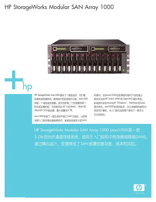
HP StorageWorks Modular SAN Array 1000HP StorageWorks msa1000提供了一款低成本、可扩展的高性能存储系统,具有强大的投资保护功能。
msa1000标配一个高性能控制器。
选件包括第二个控制器和两个附加驱动器机柜,可控制多达42个的Ultra2、Ultra3和Ultra320 SCSI 驱动器,最大容量为6 TB 。
msa1000安装了一款全新的8端口SAN 交换机,从而使该款入门级存储设备能够经济、高效地连接到大型SAN环境中。
支持msa1000的免费固件替代产品的推出使其可支持HP Tru64 UNIX ®和OpenVMS 操作系统。
标准固件支持Microsoft ®Windows ®、NetWare 和Linux 操作系统。
msa1000较低的成本,加上卓越的性能和出色的可扩展性,为入门级市场的客户提供了一款无与伦比的组合。
HP StorageWorks Modular SAN Array 1000 (msa1000)是一款2 Gb 的光纤通道存储系统,适用于入门级和中档存储域网络(SAN)。
通过精心设计,显著降低了SAN 部署的复杂度、成本和风险。
2HP StorageWorks Modular SAN Array 1000•推出的内嵌式交换机选件的特性和功能进一步增强•可与大多数惠普外部存储局域网交换机连接并实现完全互操作,且价格较低;即使在冗余配置中也无需更多机架空间•更出色的固件,支持HP Tru64 UNIX 和OpenVMS 操作系统•灵活:支持Windows 2000和NT 、NetWare 、Linux,或Tru64 UNIX 和OpenVMS 操作系统•性能:传输速率高达30K I/Ops (高速缓存),吞吐率高达200 MB•兼容:在4U 机架空间内安装了14个1英寸驱动器,1 Gb 或2 Gb 结构交换机或集线器•可扩展:使用42个146 GB 硬盘驱动器,可在10U 的机架空间内轻松扩展至6 TB •集成:允许在内部安装可选的MSA 8端口交换机,或HP StorageWorks msa 集线器2/3•可维护:支持热插拔驱动器、控制器、风扇、电源、交换机和集线器•可靠:支持最高的容错级别(RAID ADG)新特性主要特性与优点技术规格HP StorageWorks Modular SAN Array 1000msa1000正面状态指示灯(3个)•电源•检测一个或多个子系统故障•机柜管理故障驱动器模块状态指示灯(3个)•驱动器访问(中心)•在线(左边)•驱动器故障(右边)后面板上的状态指示灯(4个)•电源/鼓风机组件故障(1个)•EMU (3个)电源,a总线,b总线接口•Ultra3 SCSI到硬盘驱动器•2Gb光纤通道到主机最大驱动器数14个1英寸Ultra2、Ultra 3或Ultra320通用驱动器(msa1000机箱);使用两个附加HP StorageWorks 4200/4300机柜可扩展至42个温度范围工作:50°到95°F/10°到35°C装运:–22°到122°F/–30°到50°C注释:10,000英尺中每上升1,000英尺要降低1∞C相对湿度:工作:10%到90%非工作:高达95%输入电源要求额定输入电压:100到240伏,交流电额定输入频率:50到60赫兹额定输入电流:最大6安培输入电源(最大):549瓦*散热(最大)1876 BTU/小时*msa1000机箱4U机架外形外形尺寸(高×宽×长): 6.9×19×20.5英寸/17.5×48.3×52.1厘米重量:净重55到85磅/25.0到38.6千克装运包装外形尺寸(高×宽×长):28.5×14.81×33.13英寸/72.4×37.6×84.2厘米重量:总重75到105磅/34.0到47.6千克技术规格-续msa SAN switch 2/8光纤通道端口8个通用端口(1个内部,7个外部。
产品概述
HP StorageWorks模块化智能阵列(MSA)家族采用简单、经济、业界领先的技术,提供卓越的存储性能,同时增强投资保护
HP StorageWorks Modular Smart Array 1000 (MSA1000)是一个2 Gb光纤通道存储系统,为直连环境、小型集群及入门级和中档SAN环境提供性价比最佳的特性。
每款解决方案均具备最大传输率,可在降低管理成本的同时,加快投资回报。
MSA1000是一个可扩展的高性能存储系统,它降低了部署SAN的复杂性、费用及风险,其模块化的设计允许您按照需要来增加存储容量。
它增加了2个HP StorageWorks MSA30磁盘机柜,具备42个企业级驱动器的集合空间,因而最大存储容量可达到6 TB。
随着您的容量需求不断提高,或者连接了更多的服务器时,该解决方案中包含了所有配置和管理程序,而且无需支付预料之外的费用来购买额外许可。
MSA1000是Microsoft Exchange服务器、文件和打印任务、以及中小数据库应用的理想选择
主要特性与优点
∙在DAS到SAN (DtS)架构上建立高性能控制器:快速、轻松地迁移由大部分智能阵列控制器所保护的存储数据
∙提供广泛的操作系统支持:包括Microsoft Windows、HP-UX、Linux、
NetWare、OpenVMS和Tru64 UNIX
∙支持广泛的服务器选择:支持32位和64位HP ProLiant及Integrity动能机型以及AlphaServer系统和众多工业标准x86设备∙具备集成配置和管理工具:利用集成的标准管理和实用软件
∙利用MSA30机柜扩展容量
技术规格:。
概要HP StorageWorks Modular Smart Array 1000 (MSA1000)是2 Gb光纖通道儲存系統,專為入門級到中階儲存區域網路(SAN)而精心設計,降低SAN配置的複雜性、費用與風險,是融合系統保護的可延展、高效能儲存系統。
MSA1000的模組化設計讓使用者能夠輕鬆地隨需新增儲存容量。
可擴充至3個HP StorageWorksMSA30磁碟櫃,可容納42個企業級磁碟機,最大儲存容量可達12 TB。
所有必要的架構與管理程式全都內含,在您的容量需求成長或者附掛更多伺服器時,絕無額外授權等額外費用。
MSA1000是HP StorageWorks Modular Smart Array家族的一員,提供業界頂尖技術以滿足當今要求嚴苛而且不斷成長的儲存需求。
這些儲存解決方案提供最佳價格功能比,適用於直接附掛環境、小型叢集與入門級和中階SAN環境。
每一個解決方案都精心設計以發揮最高的傳輸率、降低管理成本,同時提供快速的投資報酬。
異質支援是Microsoft Windows® Server 2003 (32位元與64位元)、Windows 2000、Windows NT®、NetWare與Linux (32位元與64位元)作業系統的標準。
此外,這個韌體還為Tru64 UNIX®或OpenVMS環境中的Alpha伺服器提供獨立支援。
另外,HP擴大MSA1000的作業系統涵蓋範圍,增加在同質環境中的基本HP-UX支援。
主要功能MSA1000提供下列主要功能:●內建於DAS to SAN {DtS}架構的高效能控制器,實現最大的投資保障●4U機架安裝設計,融合控制器與磁碟架● 2 Gb光纖通道主機連線●配合外接式8埠4 Gb光纖通道網絡交換器●支援企業級HP Ultra2、Ultra3與Ultra320通用1"磁碟機●可透過HP StorageWorks磁碟機櫃,從1個延展到42個磁碟機,實現多達12 TB儲存容量●與Hewlett Packard、VERITAS和其他ISV備份與回存軟體相容全新功能●在同質環境中,以運用替代性MSA1000韌體定義的架構,支援業界第一名的UNIX®作業系統HP-UX。
Modular Smart Array 1000 简写成MSA1000用户现场情况:2台ES45机器,一台MSA1000带两个光纤switch,盘柜共有三个BOX附22块72G SCSI硬盘。
两台机器是单机运行。
用户的安装要求:22块硬盘做一个RAID0+1,分成11个unit。
其中3个unit为一台服务器所用,另9个unit为另一台机器所用。
安装说明如下:1.盘柜有一点不好就是,在CLI>所键入的命令一定要一个字母都不能少,不能错,否则就有错误提示。
且在终端上如果一行显示到头了,而命令还没有完成,则后面的字符将被隐藏了。
也就类似盲打了,但是一点都不能错。
错了刚重敲,且上下键不能返回上一个命令,这一点特别别扭。
2.MSA1000在创建RAID组时非常方便,一条命令能解决传统几条命令完成的工作。
安装步骤如下:1.串口线连接MSA1000,但是在controller上的接口是RJ-45Z,在设置速率时一定要是19200(默认)2.配置控制器参数:A.CLI> SET GLOBALS EXPAND_PRIORITY=HIGH REBUILD_PRIORITY=HIGHSYSTEM_NAME=”BJUNICOM” READ_CACHE=50 WRITE_CACHE=50(此步骤仅对于VMS系统需要设置,一般Tru64不需要专门设置)B.CLI> SET THIS_CONTROLLER_ID UNICOMC. CLI> SET PROMPT LeftCLI> SET PROMPT Right3. LUN 创建和管理命令:A.Left> LOCATE BOX 1Left> locate cancelLeft> LOCATE BOX 2Left> locate cancelLeft> LOCATE BOX 3Left> locate cancel (指定所有BOX上的硬盘flash LED)B. Left> add unit 0 data="disk101-disk107 disk201-disk207 disk301-disk308"raid_level=1 size=69460Left> show unit 0Left> add unit 1 data="disk101-disk107 disk201-disk207 disk301-disk308"raid_level=1 size=69460Left> show unit 1Left> add unit 2 data="disk101-disk107 disk201-disk207 disk301-disk308"raid_level=1 size=69460Left> show unit 2Left> add unit 3 data="disk101-disk107 disk201-disk207 disk301-disk308"raid_level=1 size=69460Left> show unit 3Left> add unit 4 data="disk101-disk107 disk201-disk207 disk301-disk308"raid_level=1 size=69460Left> show unit 4Left> add unit 5 data="disk101-disk107 disk201-disk207 disk301-disk308"raid_level=1 size=69460Left> show unit 5Left> add unit 6 data="disk101-disk107 disk201-disk207 disk301-disk308"raid_level=1 size=69460Left> show unit 6Left> add unit 7 data="disk101-disk107 disk201-disk207 disk301-disk308"raid_level=1 size=69460Left> show unit 7Left> add unit 8 data="disk101-disk107 disk201-disk207 disk301-disk308"raid_level=1 size=69460Left> show unit 8Left> add unit 9 data="disk101-disk107 disk201-disk207 disk301-disk308"raid_level=1 size=69460Left> show unit 9Left> add unit 10 data="disk101-disk107 disk201-disk207 disk301-disk308"raid_level=1 size=69460Left> show unit 10Left> add unit 11 data="disk101-disk107 disk201-disk207 disk301-disk308"raid_level=1 size=69460Left> show unit 11这一步就是创建各个卷,0 = RAID 0 (no fault tolerance)1 = RAID 1 (mirroring)5 = RAID 5 (distributed parity)ADG = Advanced Data Guarding (ADG)对于用户需求0+1方式,设置所有的unit在同一个磁盘组中,且raid_level=1即可实现。
MSA1000连接RX1600(HP-UX)安装7月中旬,根据用户的需求,在西宁电信安装MSA1000。
以下是安装的大致过程。
回顾安装过程,其实在刚开始就走了几个弯路。
【用户现场环境】在MSA1000安装之前,用户的存储是RX1600直连VA7110,所用的光纤是SC-LC。
操作系统为HP-UX11.23.拆开MSA1000的外包装,感觉体积不大,不过有点沉,所以在搬动MSA1000等存储的时候最好有两个人。
MSA1000的配置是 HUB 2/3,reduancy controller.由于MSA存储产品并非HP嫡系产品,用在HP-UX 平台下的很少,支持也相对较少,只是到了后期的一些版本才支持HP-UX。
其主要作为中小型企业的中低端SAN存储。
将RX1600和VA先后shutdown,更换RX1600与VA7100的SC-LC的光纤为LC-LC光纤。
先后启动MSA1000和RX1600后,ioscan根本无法看到MSA1000的设备。
在启动和dmesg信息中出现如下提示:0/2/1/0: WARNING: It appears that there are (or were) more than one device withthe same address (nport ID) setting of 0x0. One of them will be ignored.#fcmsutil /dev/td0 replace_dsk 0x0Failure in ioctl: No such device or address#fcmsutil /dev/td0 replace_dsk 0x000002Disk at nportid 0x000002(Loop_id 124) will not be authenticatedioscan仍无法查看到MSA1000设备,重启机器也始终无法解决,且上述信息仍旧发生。
HP存储MSA配置步骤和状态监控MSA是HP低端存储产品,是Modular Smart Array的缩写,我们用到的MSA系列产品有MSA20、MSA30、MSA1000和MSA1500。
MSA20和MSA30只是个傻盘柜,没有raid 功能,直接连到主机,如要配置raid则需要在主机上安装raid卡。
MSA1000/1500是盘柜加控制器,控制器可管理、配置raid,控制器外部接2Gb光纤到主机,需要主机配有HBA卡(光纤卡)。
MSA1500支持冗余路径,可保证数据的安全。
下面简单的讲解了MSA现场的配置过程和MSA远程在线的配置方法。
一、MSACLI配置步骤1配置准备:1.1主机光纤卡正确安装并与MSA控制器连接1.2MSA硬件安装完毕1.3请确认MSA控制器firmware版本为6.86或更高(仅针对配置双控负荷均担)2配置步骤:2.1配置前的准备工作2.1.1查看HP-UX主机HBA卡WWPN号用root用户登录主机,键入如下命令:(以实验室设备benz为例)root@benz:/>ioscan -fnC fcClass I H/W Path Driver S/W State H/W Type Description=================================================================fc 0 0/4/1/0 td CLAIMED INTERFACE HP Tachyon XL2 Fibre Channel Mass Storage Adapter/dev/td0root@benz:/>fcmsutil /dev/td0V endor ID is = 0x00103cDevice ID is = 0x001029XL2 Chip Revision No is = 2.3PCI Sub-system Vendor ID is = 0x00103cPCI Sub-system ID is = 0x00128cTopology = PTTOPT_FABRICLink Speed = 2GbLocal N_Port_id is = 0x010100N_Port Node World Wide Name = 0x50060b00005fc129N_Port Port World Wide Name = 0x50060b00005fc128Driver state = ONLINEHardware Path is = 0/4/1/0Number of Assisted IOs = -1536164319Number of Active Login Sessions = 1Dino Present on Card = NOMaximum Frame Size = 2048Driver Version = @(#) libtd.a HP Fibre Channel TachyonTL/TS/XL2 Driver B.11.11.12 PATCH_11.11 (PHSS_31326) /ux/kern/kisu/TL/src/common/wsio/td_glue.c: Sep 5 2005, 10:14:40注意上面红色的号码,在MSA配置中的格式为:50060b00-005fc1282.1.2查看Linux主机HBA卡WWPN号用root用户登录主机,键入如下命令:(以实验室设备jetta为例)[root@jetta ~]# cat /proc/scsi/qla2xxx/0QLogic PCI to Fibre Channel Host Adapter for QLA2340:Firmware version 3.03.18 IPX, Driver version 8.01.02-d4ISP: ISP2312, Serial# D08964Request Queue = 0x37640000, Response Queue = 0x37630000Request Queue count = 2048, Response Queue count = 512Total number of active commands = 0Total number of interrupts = 160Device queue depth = 0x10Number of free request entries = 2047Number of mailbox timeouts = 0Number of ISP aborts = 0Number of loop resyncs = 0Number of retries for empty slots = 0Number of reqs in pending_q= 0, retry_q= 0, done_q= 0, scsi_retry_q= 0Host adapter:loop state = <DEAD>, flags = 0x1a03Dpc flags = 0x4000000MBX flags = 0x0Link down Timeout = 008Port down retry = 016Login retry count = 016Commands retried with dropped frame(s) = 0Product ID = 4953 5020 2020 0002SCSI Device Information:scsi-qla0-adapter-node=200000e08b84e4b6;scsi-qla0-adapter-port=210000e08b84e4b6;FC Port Information:SCSI LUN Information:(Id:Lun) * - indicates lun is not registered with the OS.若要查看主机上的第二快HBA卡,命令为cat /proc/scsi/qla2xxx/12.1.3查看AIX主机HBA卡WWPN号用root用户登录主机,键入如下命令:(以湖南SCP11A为例)root@SCP11A>lsattr -El dac0GLM_type low GLM type Falsealt_held_reset no Alternate held in reset Falsecache_size 128 Cache Size in MBytes Falsecontroller_SN 1T54396785 Controller serial number Falsectrl_type 1722-600 Controller Type Falselocation Location Label Truelun_id 0x0 Logical Unit Number Falsenode_name 0x200800a0b81f56e8 FC Node Name Falsepassive_control no Passive controller Falsescsi_id 0x10000 SCSI ID Falseutm_lun_id 0x001f000000000000 Logical Unit Number Falseww_name 0x200900a0b81f56e9World Wide Name False注意上面红色的号码,在MSA配置中的格式为:200900a0-0b81f56e92.1.4连接MSA控制器方法:找一台PC机,通过阵列随机带的黑色串口线(维护线,一端串口,一端RJ45口),将PC机和阵列的控制器连接起来。
DCS-1000G 操作手册© Mettler-Toledo , Inc. 2007Mettler Toledo 版 权 所 有。
未 经 许 可 不 得 翻 印、 修 改 或 引用。
METTLER TOLEDO 为 Mettler-Toledo, Inc 的 注 册 商 标目录1. 概况 (1)2. 产品基本参数和主要技术性能指标 (1)3. 主要结构介绍 (1)4 PANTHER 称重控制终端主要操作说明 (2)4.1P A N T H E R仪表各功能键说明 (2)4.2秤的标定及标准参数设定 (3)5. 操作说明 (5)5.1 控制面板说明 (5)5.2 控制柜上电及秤的手动操作 (6)5.3 控制柜断电操作 (6)5.4 初始化操作 (7)5.5 秤的自动操作 (7)5.5.1 包装过程的自动操作 (7)5.5.2超差告警的处理及自动工作的再启动 (7)5.5.3自动工作过程的中止 (7)5.5.4自动工作过程的中途退出 (8)5.5.5自动工作过程的振动 (8)6.触摸屏人机界面说明 (8)7. 维护和保养 (15)附录1 :PANTHER 参数一览表 (16)1.概况IBC980电子包装秤是梅特勒-托利多(常州)称重设备系统有限公司在现有DCS 型电子包装秤的基础上延伸开发的产品,主要针对集装袋(Intermediate Bulk Container)的包装形式,用于散状物料的自动定量包装。
2.产品基本参数和主要技术性能指标适用物料:具有良好流动性的粉、粒状物料。
(例如:PET、PBT、PTA等)适用包装袋:柔性集装袋,有如下特性:PP编织材料(PE内衬膜或PE淋膜)4只悬挂吊耳公称容积 800~1300L (GB/T10454-2000)包装净重:800~1000kg/包;计量精度:±0.8kg (HG20547-92)包装速度:15~20包/小时使用温度: -10℃~+40℃输送方式:输送机运输(托盘-辊道式)3.主要结构介绍IBC980采用毛重称重方式。
HP MSA 1000安装及配置手册
1、将MSA1000后面出厂原装的单端口光纤接口板拆除,换上MSA SAN Switch 2/8光纤交
换机。
具体参考出厂包装中的硬件安装说明手册。
需要注意的是:虽然MSA1000背部有两块接口板插槽位置,但是MSA SAN Switch 2/8光纤交换机不能和原装的单端口光纤接口板同时使用。
不过可以将原来的SFP模块拆下来安装到MSA SAN Switch 2/8光纤交换机上使用。
2、按照前面板上的插槽编号从1开始依次把硬盘装上。
3、将测试机器关掉,把HBA光纤卡装好。
并连接好光纤线。
注意反正。
此机器作为MSA1000
的管理服务器。
重新启动后,将MSA光盘包中的Support Software for Windows光盘放进去,自动运行后,首先接受软件协议,然后会自动开始搜索管理服务器上的HBA卡及通过HBA卡连接的MSA存储。
4、安装完硬件驱动后进入管理软件安装界面,可以根据需要从左上到右下依次选择需要安
装的软件,建议安装如图三项即可。
注意安装过程中的提示,安装驱动后提示重启时不要重新启动机器,一直到安装完所有软件后再重新启动机器。
5、重新启动完成后,从开始菜单打开HP Array Configuration Utility。
6、执行模式选择为本地应用模式
7、在打开的窗口中可以看到连接的MSA1000存储及配置情况。
选择Express
Configuration。
8、开始配置向导
9、选择RAID模式为RAID5
10、选择需要定义热备盘以提高数据安全性。
11、确认配置,开始应用。
12、配置完成
13、打开管理服务器的计算机管理 磁盘管理。
会发现新认到的磁盘驱动器,并且提示
用户是否要将新磁盘升级为动态磁盘。
作双机的话不要升级到动态磁盘,取消之后创建分区即可。
以下是升级到动态磁盘的步骤。
14、升级完后,需要将该硬盘使用起来,右键选择创建卷。
15、如果做双机的话,此处最好选择靠后的驱动器符号,以防在后面的双机配置时冲突。
16、到资源管理器里面确认一下新建的M盘是否能够正常使用。
17、至此,MSA1000安装及配置完成。
iGrid
2009年2月28日。