DTSF666说明书 (1)
- 格式:doc
- 大小:1.78 MB
- 文档页数:8
1.读卡器或售电机操作说明书(RW666型)正泰售电机管理系统软件(RW666型IC读卡器)一、安装好售电系统后(不要安装在C盘),装好读卡器的电源线、数据线连接上后,系统提示发现新硬件,安装好驱动后。
将电表包装盒内的“购电卡”插入读卡器(箭头指示的方向朝上,推进出用力压到位,直到不能弹出后松手)。
拔卡方法:再压-松手弹出。
二、适用于:正泰生产DDSY666、DTSY666电能表产品。
三、进入软件:系统默认管理员123,密码123,进入.四、修改电价:用户管理→电价维护→删除不需要的电价类型→双击需要修改的电价单价值→改成小区售电电价→保存五、修改密码(此步骤由用户决定是否修改)用户管理→修改密码→原密码123→输入两遍新密码→确定六、建档用户管理→档案管理→增加→用户编号、电表编号任意编制数字(用户号可以与电表号相同但不能与档案中已存在的其他用户相同,即一户一号),输入用户名称(如张三,可不写)、输入用户地址(如1号楼1单元101),证件代码、用户电话可输可不输,电表类型选择单相电能表(如果是三相表就选择三相表,当选择三相表后弹出CT值,一般为1,加互感器的除外,后面有说明。
)→点击保存→出现提示是否制作初始化卡→点击“是”→将新卡插入读卡器→点初始化卡操作中的“写卡”输入一级报警:10,二级报警:5,负荷阀值:40 (电表的最大工作电流,家用电器实际工作电流≥设置数值,电表自动跳闸断电,例如:5/20A电表,最大工作电流20A,10/40A电表,最大工作电流40A,如果用户负载或电器功率大,最大工作电流+10A)→选择电价类型→选中“度数或金额”→输入第一次售电度数或者金额→点击“确认写卡”→出现初始化卡制作成功→拨出读卡器中的卡→在卡的背面标注用户名“张三”→发卡给张三。
这里需要注意一点:做好的初始化卡第一次插入哪块电表后,以后该表只认这张卡,而这张卡也只能给这块表充电,所以第一次卡一定插对。
DTSU666.001型三相四线电子式电能表(导轨)DSSU666.001型三相三线电子式电能表(导轨)使用说明书ZTY0.464.1002浙江正泰仪器仪表有限责任公司二0二一年十一月1.概述1.1.主要用途及适用范围DTSU666系列三相四线和DSSU666系列三相三线电子式电能表(导轨)(以下简称“仪表”)是采用大规模集成电路,应用数字采样技术,是针对电力系统、通信行业、建筑行业等电力监控和电能计量需求而设计,主要对电气线路中的三相电压、三相电流、有功功率、无功功率、频率、正反向电能、四象限电能等参数进行实时测量与显示,采用标准DIN35mm导轨式安装;做为能源管理系统的监测终端产品,可广泛应用于工矿企业、宾馆、学校、大型公建内部电能考核与监测。
该电能表性能指标符合以下相关技术标准:GB/T 17215.211-2021《电测量设备(交流)通用要求、试验和试验条件》GB/T 17215.321-2021《电测量设备(交流)特殊要求第21部分:静止式有功电能表(A级、B 级、C级》GB/T 17215.323-2008《交流电测量设备特殊要求-第23部分:静止式无功电能表(2级和3级)》DL/T 645-2007《多功能电能表通信协议》MODUS-RTU protocol.1.2.产品特点具有正反向有功、组合有功、组合无功、四象限无功电能计量和存储功能,组合方式特征字可设;具有RS485通信口,支持ModBus-RTU或DL/T 645-2007协议;可支持多费率功能,支持尖、峰、平、谷四个费率,支持需量测量;可支持外控功能,最大支持2路继电器输出;DIN35mm标准导轨式安装,结构模数化设计,体积小、易安装;1.3.产品型号的组成及代表意义图 1产品型号组成表 1产品型号及常用规格注:1.5(6)A为经电流互感式接入,5(80)A为直接接入式。
1.4.使用环境条件1.4.1.温度范围户内式:规定工作温度范围:-10℃~+45℃,极限工作温度范围:-25℃~+70℃;1.4.2.相对湿度(年平均)小于75%RH。
dtsf633电表说明书
1.电能表型号及其含义
电能表型号是用字母和数字的排列来表示的,内容包括类别代号+组别代号+
设计序号+派生号。
(1)类别代号。
D一电能表。
(2)组别代号。
1)表示相线:D一单相;T一三相四线有功;S一三相三线有功;X一三相
无功。
2)表示用途:B一标准;D一多功能;M一脉冲;S一全电子式;Z一大需量。
Y一预付费:F一复费率。
(3)设计序号。
用阿拉伯数字表示。
(4)派生号。
T一湿热、干燥两用;TH一湿热带用;TA一干热带用;G一
高原用;H一船用;F一化工防腐用。
例如:
DD表示单相电能表,如DD862型,DD701型,DD95型。
DS表示三相三线有功电能表,如DS8、DS310、DS864型等。
DT表示三相四线有功电能表,如DT862型、DT864型。
DX表示无功电能表,如DX8、DX9、DX310、DX862型。
DZ表示大需量表,如DZl型。
DB表示标准电能表,如DB2型,DB3型。
如题电表10(40A)和5(40A)有区别,好些,还有3200转和4000转的,好些个容量大些?一、10(40A)表示通过它的电流范围是0-40A,一般电流在
10A左右时电表计度准确,大可以承受40A,电流大于40A,可能就要把表烧了,单相负载功率范围为0-2200-8800W,也就是说电表大可以承受40A,即
8800W;。
DTSU666-H 100 A and 250 A Smart Power Sensor User ManualIssue04Date2021-03-01Copyright © Huawei Technologies Co., Ltd. 2021. All rights reserved.No part of this document may be reproduced or transmitted in any form or by any means without prior written consent of Huawei Technologies Co., Ltd.Trademarks and Permissionsand other Huawei trademarks are trademarks of Huawei Technologies Co., Ltd.All other trademarks and trade names mentioned in this document are the property of their respective holders.NoticeThe purchased products, services and features are stipulated by the contract made between Huawei and the customer. All or part of the products, services and features described in this document may not be within the purchase scope or the usage scope. Unless otherwise specified in the contract, all statements, information, and recommendations in this document are provided "AS IS" without warranties, guarantees or representations of any kind, either express or implied.The information in this document is subject to change without notice. Every effort has been made in the preparation of this document to ensure accuracy of the contents, but all statements, information, and recommendations in this document do not constitute a warranty of any kind, express or implied.Huawei Technologies Co., Ltd.Address:Huawei Industrial BaseBantian, LonggangShenzhen 518129People's Republic of ChinaWebsite:https://About This DocumentPurposeThis document describes the DTSU666-H (100 A/40 mA) and DTSU666-H 250A/50 mA Smart Power Sensor in terms of its functions, electrical properties, andstructure. DTSU666-H (100 A/40 mA) is abbreviated as DTSU666-H.Figures provided in this document are for reference only.Intended AudienceThis document is intended for:●Sales engineers●Technical support engineers●Maintenance engineersSymbol ConventionsThe symbols that may be found in this document are defined as follows.Change HistoryChanges between document issues are cumulative. The latest document issuecontains all updates made in previous issues.Issue 04 (2021-03-01)Updated 4.4 Structure Specifications.Issue 03 (2019-12-10)●Updated 2.5 Product Structure.●Updated 4.4 Structure Specifications●Added 5 Current Transformer.Issue 02 (2019-08-30)Added the DTSU666-H 250 A/50 mA Smart Power Sensor.Issue 01 (2018-03-01)This issue is the first official release.ContentsAbout This Document (ii)1 Safety Precautions (1)2 Overview (4)2.1 Product Overview (4)2.2 Working Principles (5)2.2.1 Conceptual Diagram (5)2.2.2 Functions (6)2.3 Application Scenarios (9)2.4 Model Naming Conventions (10)2.5 Product Structure (11)3 System Maintenance (14)3.1 Troubleshooting (14)4 Technical Specifications (16)4.1 Environmental Specifications (16)4.2 Main Technical Performance and Parameters (16)4.3 EMC Specifications (18)4.4 Structure Specifications (19)5 Current Transformer (22)6 Acronyms and Abbreviations (26)1 Safety Precautions General Safety●Follow the precautions and special safety instructions provided by Huaweiwhen operating this product. Personnel who plan to install or maintainHuawei devices must receive a thorough training, understand all necessarysafety precautions, and be able to correctly perform all operations. Themanufacturer will not be liable for any consequences that are caused by theviolation of general safety regulations and device usage safety standards.●Before performing operations, read through this manual and follow all theprecautions to prevent accidents. The "DANGER", "WARNING", "CAUTION",and "NOTICE" statements in this document do not represent all the safetyinstructions. They are only supplements to the safety instructions.●Operation personnel should comply with local laws and regulations. Thesafety instructions in this document are only supplements to local laws andregulations.●Do not operate the product or handle cables during thunderstorms.●Before operating the product, remove any conductors such as jewelry orwatches.●Use insulated tools during operations.●Follow specified procedures during installation and maintenance. Do notattempt to alter the device or deviate from the recommended installationprocedures without prior consent from the manufacturer.●Install the product in strict accordance with the quick guide. DisclaimerThe manufacturer shall not be liable for any consequence caused by any of thefollowing events:●Transportation damage.●The storage conditions do not meet the requirements specified in thisdocument.●Incorrect installation or use.●Installation or use by unqualified personnel.●Failure to obey the operation instructions and safety precautions in thisdocument.●Operation in extreme environments which are not covered in this document.●The DTSU666-H or DTSU666-H 250 A/50 mA operates beyond specifiedranges.●Unauthorized modifications to the product or software code or removal of theproduct.●Device damage due to force majeure (such as lightning, fire, and storm).●The warranty expires and the warranty service is not extended.●Installation or use in environments which are not specified in relatedinternational standards.Personnel RequirementsOnly certified electricians are allowed to install, connect cables for, maintain,troubleshoot, and replace the DTSU666-H or DTSU666-H 250 A/50 mA.●Operation personnel should receive professional training.●Operation personnel should read through this document and follow all theprecautions.●Operation personnel should be familiar with the safety specifications aboutthe electrical system.●Operation personnel should understand the composition and workingprinciples of the grid-tied PV power system and local regulations.●Operation personnel must wear proper personal protective equipment (PPE). Protect LabelsDo not scrawl or damage the nameplate on the back of the DTSU666-H orDTSU666-H 250 A/50 mA because it contains important product information. Installation●Ensure that the DTSU666-H or DTSU666-H 250 A/50 mA is not connected toa power supply or powered on before finishing installation.●To allow proper heat dissipation and installation, maintain appropriateclearances between the DTSU666-H or DTSU666-H 250 A/50 mA and otherobjects.Electrical ConnectionsBefore connecting cables, ensure that the DTSU666-H or DTSU666-H 250 A/50 mAis not damaged in any way. Otherwise, electric shocks or fire may occur.●Ensure that all electrical connections comply with local electrical standards.●Ensure that the cables used in a grid-tied PV system are properly connectedand insulated and meet all specification requirements.OperationHigh voltage may cause an electric shock, which results in serious injury, death, orserious property damage from the DTSU666-H or DTSU666-H 250 A/50 mA inoperation. Strictly comply with the safety precautions in this document andassociated documents when operating the DTSU666-H or DTSU666-H 250 A/50mA.●Do not touch an energized DTSU666-H or DTSU666-H 250 A/50 mA becauseit may result in an electric shock.●Follow local laws and regulations when operating the device. Maintenance and ReplacementHigh voltage may cause an electric shock, which results in serious injury, death, orserious property damage from the DTSU666-H or DTSU666-H 250 A/50 mA inoperation. Therefore, before maintenance, power off the DTSU666-H or DTSU666-H 250 A/50 mA and strictly comply with the safety precautions in this documentand associated documents to operate the DTSU666-H or DTSU666-H 250 A/50mA.●Maintain the DTSU666-H or DTSU666-H 250 A/50 mA with sufficientknowledge of this document and proper tools and testing devices.●Temporary warning signs or fences must be placed to prevent unauthorizedpeople from entering the site.●The DTSU666-H or DTSU666-H 250 A/50 mA can be powered on only after allfaults are rectified. Failing to do so may escalate faults or damage the device.●During the maintenance, observe ESD precautions and wear ESD gloves.2 Overview2.1 Product OverviewType DTSU666-H and DTSU666-H 250 A/50 mA Smart Power Sensor (here in afterreferred to as the "sensor") adopts large-scaled integrated circuit with digitalsampling technology, specially designed for power monitoring and energymetering demands including power system, communication industry, constructionindustry, mainly applied into real-time measurement and display for parameterssuch as three phase voltage, three phase current, active power, reactive power,frequency, positive and reverse energy, four quadrant electric energy, etc. Adoptingthe standard DIN35mm din rail mounting, structural module design, it ischaracterized with small volume, easy installation and networking, etc. As amonitoring terminal product towards energy management system, it can bewidely applied into internal power assessment and monitoring of the industrialand mining enterprises, hotels, schools, large public buildings.This performance index of the meter conforms to the following relevant technicalstandard:●EN 61326-1:2013●IEC 61326-1:2012●EN 61326-2-1:2013●IEC 61326-2-1:2012●EN 61010-1:2010●IEC 61010-1:2010●EN 61010-2-1:2010●IEC 61010-2-1:2010Figure 2-1 DTSU666-H or DTSU666-H 250 A/50 mA2.2 Working Principles2.2.1 Conceptual DiagramThe instrument is composed of highly accurate metering integrated circuit (ASIC),management MCU, storage chip, RS485 communication module, etc. Theconceptual diagram is shown in Figure 2-2.Figure 2-2 Conceptual diagram2.2.2 Functions●Display function:The displayed interfacial electrical parameter and power data are bothprimary-side data (which is calculated based on the value of the current andvoltage). The energy measurement value is displayed in seven bits, with thedisplay range from 0.00kWh to 999999.9kWh.Liquid crystal displayFigure 2-3Table 2-1 Display (auto loop)NO T EIf no button is pressed for 60 seconds, the backlight turns off. Auto loop Switch time = 5s.Table 2-2 Display (change by key)NO T E●Change by key "".●Comb. active energy = Imp. active energy – Exp. active energy●Programming function:Table 2-3 Programming function●Programming operation:NO T ECommunications parameters have been configured for the power meter beforedelivery. If the communication is abnormal, check and set the parameters.Button description: SET represents confirm or cursor shift (when entering digits), ESC represents exit, and → represents add. The password is 701 by default.Figure 2-4 Setting example for modifying communication address or baud rate●Communication functionThe Sensor has an RS485 communication interface, the baud rate can bechanged between 1200 bps, 2400 bps, 4800 bps and 9600 bps. The defaultCommunication parameters is 9600 bps, none parity bits and 1 stop bit, andcommunication addresses (see factory numbers or LCD display), supportModBus RTU protocol.2.3 Application ScenariosScenario 1: In the residential power station scenario (three-phase grid), sometimesaccording to the requirements of the grid, it is necessary to limit the active powerof the grid-connected point. At this time, the smart power sensor needs to collectthe power information of the grid-connected point to control the output power ofthe inverter. With the cooperation of energy storage batteries, it is also necessaryto use meters to increase the self-consumption. It adopts RS485 communication,which can realize the electrical quantity measurement and energy meteringfunction, and respond to the upper host for the real-time data query.Scenario 2: In commercial roof power plants, sometimes according to therequirements of the power grid, it is necessary to limit the active power of grid-connected points. At this time, the smart power sensor needs to collect the powerinformation of the grid-connected point to control the output power of theinverter. It adopts RS485 communication, which can realize the electrical quantitymeasurement and energy metering function, and respond to the upper host forthe real-time data query.Figure 2-5Application Scenarios2.4 Model Naming ConventionsFigure 2-6Model naming conventionsTable 2-4 Model specificationNO T EPlease take the physical label as standard.2.5 Product StructureFigure 2-7 Product dimensions (Smart Power Sensor)Figure 2-8 100 A CT dimensionsFigure 2-9 250 A CT dimensionsAppearanceDifferences between DTSU666-H and DTSU666-H 250 A/50 mA:●Parameters on the panelFigure 2-10 DTSU666-HFigure 2-11 DTSU666-H 250 A/50 mA●NameplateFigure 2-12 DTSU666-HFigure 2-13 DTSU666-H 250 A/50 mAPerformance and SpecificationsTable 2-6 Performance and specifications3 System Maintenance 3.1 TroubleshootingNO T EContact the installation vendor if all failure analysis procedures listed above are completed and the fault still exists.4 Technical Specifications4.1 Environmental SpecificationsTable 4-1 Environmental specifications4.2 Main Technical Performance and Parameters Electrical ParametersTable 4-2 Electrical parametersPercentage ErrorTable 4-3 Limited value of active percentage error of the energy meter on balanced loadTable 4-4 Limited value of active percentage error of the energy meter on unbalanced loadStartUnder the power factor of 1.0 and 2‰ In, the instrument can be started withcontinuous metering (if it is multiple phase instrument, then it has balanced load).If the instrument is designed based on measurement for bi-directional energy,then it is suitable for each direction of energy.DefluctionWhen applying voltage while the current circuit has no current, the test output ofthe instrument shall not produce a superfluous pulse. When testing, the currentcircuit shall be disconnected and the applied voltage of the voltage circuit shall be115% of the referenced voltage.The shortest testing time :For instrument of class 1:From the formula: k represents energy meter constant (imp/kWh), m representsthe testing component quantity, U n represents the referenced voltage (V), I maxrepresents the large current (A).Other Technical ParametersTable 4-5 Other technical parameters4.3 EMC SpecificationsEMC performance of the meter conforms to the following relevant technicalstandard:●IEC 61326-1:2012●IEC 61326-2-1:2012●EN 61326-1:2013●EN 61326-2-1:2013●EN 61000-3-2:2005/A2:2009●EN 61000-3-3:20084.4 Structure SpecificationsTable 4-6 Structure specifications1.Install the smart power sensor on the standard din rail of DIN35mm.2.Install the Smart Power Sensor to the standard din rail from the top to thebottom, and then push the instrument to the din rail from the bottom to thefront part.Figure 4-1 Install the smart power sensorNO T EA fuse and a thermistor are connected to each phase of Ua, Ub, and Uc inside the powermeter to prevent damage caused by external short circuits. Ua, Ub, and Uc do not need tobe protected by external fuses.DTSU666-H or DTSU666-H 250 A/50 mA Wiring Terminal Instruction (Three-Phase Four-Wire)NO T E●The minimum cable diameter must comply with local cable standards.●The factors that affect cable selection include the rated current, cable type, routingmode, ambient temperature, and maximum expected line loss.Operating voltage: 0.7–1.3 Un1.Three phase four wire: Connect the Ua, Ub, Uc, Un voltage lines to the 3, 6, 9and 10 terminals of the collector. Connect current transformer outlets IA*, IA,IB*, IB, IC*, IC to terminals 13, 14, 16, 17, 19, 21 of the collector.2.Connect RS485A and RS485B to the communication host.NO T E●In the SmartLogger networking, the RS485A and RS485B need to connect to theSmartLogger. In the Smart Dongle networking, the RS485A and RS485B need to connectto the inverter.●The CT direction must be consistent with the arrow direction as shown in the precedingfigure.Figure 4-2 Three-phase four-wire (supported model: DTSU666-H or DTSU666-H250 A/50 mA)DTSU666-H 250 A/50 mA Wiring Terminal Instruction (Three-Phase Three-Wire)Operating voltage: 0.7–1.3 Un1.Three phase three wire: Connect the Ua, Uc, Ub voltage lines to the 3, 9 and10 terminals of the collector. Connect current transformer outlets IA*, IA, IB*,IB, IC*, IC to terminals 13, 14, 16, 17, 19, 21 of the collector.2.Connect RS485A and RS485B to the communication host.NO T E●In the SmartLogger networking, the RS485A and RS485B need to connect to theSmartLogger. In the Smart Dongle networking, the RS485A and RS485B need to connectto the inverter.●The CT direction must be consistent with the arrow direction as shown in the precedingfigure.Figure 4-3 Three-phase three-wire (supported model: DTSU666-H 250 A/50 mA)5 Current TransformerApplicationThis product is suitable for 50 Hz multi-function electronic energy meter, anti-theftmeter, digital display and other electrical measuring equipment.This performance index of the current transformer conforms to the followingrelevant technical standard:●JB/T 10665-2016●JJG 313-2010Environmental SpecificationsTable 5-1 Environmental specificationsElectrical ParametersTable 5-2 Electrical parametersElectrical Circuit DiagramFigure 5-1 Electrical Circuit DiagramProduct SizeThe following figures show the CT structure of the DTSU666-H and DTSU666-H250 A/50 mA meters.Figure 5-2 CT structure of the DTSU666-HFigure 5-3 CT structure of the DTSU666-H 250 A/50 mA6 Acronyms and Abbreviations DDCdirect current EEFTelectrical fast transient EMIelectromagnetic interference EMSelectromagnetic susceptibility ESDelectrostatic discharge MMPPTmaximum power point tracking RREradiated emission RS radiated susceptibilityDTSU666-H 100 A and 250 A Smart Power Sensor User Manual 6 Acronyms and AbbreviationsIssue 04 (2021-03-01)Copyright © Huawei Technologies Co., Ltd.26。
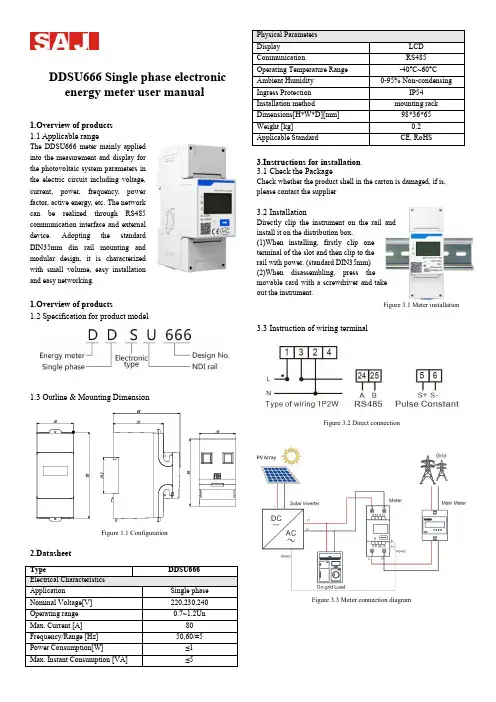
DDSU666 Single phase electronicenergy meter user manual1.Overview of products 1.1 Applicable rangeThe DDSU666 meter mainly applied into the measurement and display for the photovoltaic system parameters in the electric circuit including voltage, current, power, frequency, power factor, active energy, etc. The network can be realized through RS485 communication interface and external device. Adopting the standard DIN35mm din rail mounting and modular design, it is characterized with small volume, easy installation and easy networking.1.Overview of products1.2 Specification for product model1.3 Outline & Mounting DimensionFigure 1.1 Configuration2.Datasheet3.Instructions for installation 3.1 Check the PackageCheck whether the product shell in the carton is damaged, if is, please contact the supplier3.2 InstallationDirectly clip the instrument on the rail and install it on the distribution box.(1)When installing, firstly clip one terminal of the slot and then clip to the rail with power. (standard DIN35mm) (2)When disassembling, press the movable card with a screwdriver and take out the instrument.Figure 3.1 Meter installation3.3 Instruction of wiring terminalFigure 3.2 Direct connectionFigure 3.3 Meter connection diagram3.4 RS485 interface of inverterFigure 3.4 RS485 pinTable 3.1 RS485 pin port definition4.Fault and troubleshooting5.Displayed functionsWhen the energy meter is in normal working condition (on loadstate), the positive pulse indicator should be flashed. If long time for no flashing or light for the indicator, please check whether the wiring mode of the energy meter is right or not.Table 5.1 LCD logo meanings6.Export limitation function settingThe steps for matching R5 series inverters are as follows: (1)Download eSolar O&M APPWeb to eSolar website https:// to scan the QR code and download “eSolar O&M” APP (or download it from Google Play or App Store by searching “eSolar O&M”). After the installation on your phone, please login it with your installer account.(2)Log in APP→ Click “My” → Click “Remote control” → Click “WiFi” /“Bluetooth”→ Click “Next step”. as shown in Figure6.1. Please refer to WiFi/GPRS/4G module manual for detailed connection operation.(3)Enter “local connect” page and select “Export limitation setting” → input password :201561 as shown in Figure6.2.Figure 6.1 Local connect Figure 6.2 Export limitation setting(4)Turn on “export limitation ”, Wait for 15s countdown seconds to set successfully ,supply the power mode and current mode ,as shown in Figure6.3 and Figure6.4Figure6.3 Countdown interface Figure6.4 Power limit/Current limit settingNote:1.Power mode and current mode could be alternatively selected;2.The setting parameter cannot exceed the given range value3.When the setting is completed, the export limitation system will begin to run.。
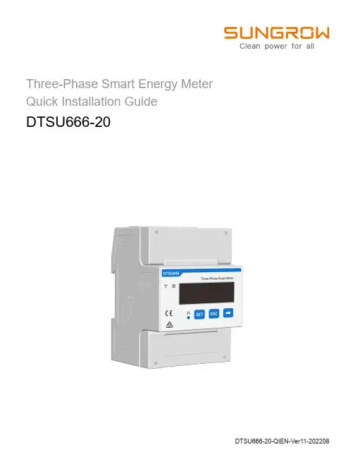
Three-Phase Smart Energy MeterQuick Installation GuideDTSU666-20DTSU666-20-QIEN-Ver11-202208This manual is applicable to Sungrow Three-phase Smart Energy Meter.Keep the manual in a convenient place for future reference. The latest manual can be acquired at .DTSU666-20ApplicabilityOnly qualified personnel with the following skills are allowed to perform the work described in this document:Training in the installation and commissioning of the electrical systems.Familiar with the country/regional standards and specifications.Capable of coping with the dangerous and emergency situations during the installation and commissioning.Knowledge of and compliance with this manual and other related documents.Target GroupThe Smart Energy Meter is designed for indoor use only. It is a measuring device detecting the electrical values at the grid-connected point. It cannot be used for billing purposes. The data collected by the Smart Energy Meter on the PV power generation may differ from the data of the main Smart Energy Meter.Any use other than those described in this document does not qualify as appropriate usage and is prohibited. Do not make any modifications to the product.Damage or destruction may be caused to the Smart Energy Meter due to inappropriate usage. The Smart Energy Meter must not be operated beyond the values specified in the technical data.The following figure shows an application example of the Smart Energy Meter in the PV system. The inverterIntended Use* The RS485 cable is included in the accessories of the meter or the inverter.Related components in the scope of delivery: Smart Energy MeterRS485 cable *Quick installation guideDelivery ContentsTechnical Data320Vac ... 460Vac***/0.333V Nominal voltage Input voltage range 50Hz/60HzGrid frequency -25 ℃ ... +70 ℃Operating temperature < 75%(non-condensing )Relative humidity 118 x 72 x 65.5 mmDimensions (W x H x D)RS485 cableDTSU666-20Quick guideCurrent TransformerThree-phase Smart Energy Meter and its terminalsThree-phase Smart Energy Meter dimensions100 A CT dimensions250 A CT dimensionsDEFGLeft elevation* The current transformer (CT) is shipped separately or with the inverter.Step 3 Connect the plugs A and B to terminals A and B on the Smart Energy Meter.Mount the Smart Energy Meter to a 35 mm DIN rail. Hook it into the top edge of the rail and press down until it snaps into place.InstallationCable ConnectionThe line conductor L1 supplies power to the Smart Energy Meter. The line conductor L1 and neutral conductor must be connected to the terminal 2 and terminal 10 of the Smart Energy Meter respectively.If there is only L1(to terminal 2), or L2 (to terminal 5), or L3 (to terminal 8), and the neutral conductor (to terminal 10), then the three-phase Smart Energy Meter can be used as a single-phase Smart Energy Meter.Step 1 Turn off solar switch, load switch, main switch and other power switches, and secure them against reconnection.Step 2 Take out the RS485 cable from inverter’s packaging or Smart Energy Meter’s packaging .Output terminals to the load sideA 2, 5, 8, 10D C A, BB LCD display Key Displays active energy and reactive energy, etc SET: confirm the selection or settingsESC: return to a previous menu or cancel the settings →: increase the setting value Communication terminals E 1, 3, 4, 6, 7, 9CT1 Current Input F 31, 33, 34, 36, 37, 39CT2 Current InputG91Power supply of Rogowski coil (5V)Step 4 Strip the insulation from the power wires by 10 mm. Then connect wires to the terminals on the Smart Energy Meter, as shown below. ( Cross-section: 1mm to 6mm )Retrofit (Three-phase hybrid inverter + Three-phase PV inverter + Three-phase grid)Retrofit (Three-phase hybrid inverter + Single-phase PV inverter + Three-phase grid)Retrofit (Single-phase hybrid inverter + Single-phase PV inverter + Single-phase grid)Step 5 For inverter cable connection, refer to the user manual of the corresponding inverter.Step 6 Cover the Smart Energy Meter with the insulating cover or contact protection of the sub-distribution. Switch on the power supply to the sub-distribution.The CT direction must be consistent with the arrow direction as shown in the preceding figure.The maximum torque of 2, 5, 8 and 10 terminal screws is 1.7N.m, and the recommended torque is (1.0 ± 0.1) N.m; The maximum torque of 13, 14, 16, 17, 19, 21, 24 and 25 terminal screws is 0.4N.m, and the recommended torque is (0.20 ± 0.05) N.m.NOTICEFor details about the installation direction and cable connection of the current transformer, please refer to the information on the side of the current transformer.Note:Connect CT1 to terminal 1 and terminal 3 of the smart energy meter, and CT2 to terminal 31 and terminal 33.From the displayed interface, the electrical parameter and energy data are all primary side data (that is, the multiplied by current and voltage ratios). The energy measuring value will be displayed seven bits, with the displaying range from 0.00kWh to 9999999MWh.Displayed function8First channelPhase A voltage =5.002ACombined phase active power 23When RS485 communicating, the telephone sign will flashes.The communication address of Modbus protocol is 1 decimal data (1 ~ 254), and the factory default baud rate is 9600bps, N.8.1; E1 means even check one stop bit, O1 means odd check one stop bit, N2 means two stop bits without check, N1 means one stop bits without check.PFb=0.500PFc=-0.500The meter parameters have been set before delivery. It can be installed directly after acception and there is no need to set parameters again. Button description: “SET” represents “confirm” or “cursor shift” (when input digits), “ESC” represents “exit”, and “→” represents “add”. The password is 701 by default.Programming functionProgramming ParameterProgramming ParameterParameterValue range DescriptionVoltage ratio, used for setting the voltage ratio of the input loop.When the voltage is connected to the line via the transformer, Pt= the rated voltage of the primary loop / the rated voltage of the secondary circuit.When the voltage is directly connected to the line, Pt shall be set as 1.0.1: 6452: n.23: n.14: E.15: O.1Settings for communication stop bit and Parity: bits1: 645mode2: None parity, 2 stop bits, n.23: None parity, 1 stop bit, n.14: Even parity, 1 stop bit, E.15: Odd parity, 1 stop bit, O.10: 1.2001: 2.400 2: 4.8003: 9.600Communication baud rate: 0: 1.200 bps 1: 2.400 bps 2: 4.800 bps 3: 9.600 bps1 ~ 254 Communication address 0: n.34 1: n.33Option for wiring mode:0: n.34 represents three phase four wire 1: n.33 represents three phase three wire0: P01: P1Pulse output:0 ~ 30Display in turns(second) 0: Timely display1 ~ 30: Time interval of actual display 0 ~ 30Backlight lighting time control(minute)0: Normally light 1 ~ 30: Backlight lighting time without button operation1 ~ 880.1 ~ 1.01:CT01:100A/333mV 2:CT02:250A/333mV 3:CT03:400A/333mV 4:CT04:500A/333mV 5:RS01:1000A/333mV 6:RS02:2000A/333mV 7:RS03:3000A/333mV 8:RS04:4000A/333mVP0: First channel actsive energy pulseP1: Second channel actsive energy pulseWhen input digits, “ ” can be used as cursor “ - ”motion button, “ ”is “add” button, “ ”is Exit the programming operation interface or switch to the character interface from digit modification interface, add from the beginning after setting the digit to the maximum value.Troubleshooting1. If the wiring mode is incorrect, please connect based on the correct wiringmode.2. If the supplied voltage is abnormal, pleasesupply the voltage on the instrument specification.1. If any problems for the communication cable, please change the cable.2. Set the address, baud rate, data bit and parity bit of the instrument to be the same as the inverter through buttons and so as the "parameter setting".1. For wrong wiring, please connect based on the correct wiring mode.2. If a negative value is displayed, change the cable connection mode of the current transformer to ensure that the high and low ends are connected properly.No display after theinstrument being powered onAbnormal RS485 communicationPower metering inaccuracy1. Incorrect wiring mode.2. Abnormal voltage supplied for theinstrument.1. The RS485 communication cable is disconnected, short circuit or reversely connected.2. The address, baud rate, data bit and parity bit of the instrument is not in accordance with the inverter.whether the corresponding phase sequence of voltage and current is correct.2. Check whether the high and low ends of the current transformer inlet are reversely connected. Pa, Pb , and Pc are abnormal if the values are negative.21。
DDSU666系列单相电子式电能表(导轨)使用说明书ZTY0.464.922浙制00000205号浙江正泰仪器仪表有限责任公司二0一六年八月目录1.概述 (1)2.工作原理 (2)3.主要技术性能与参数 (3)4关键零部件采用 (4)5.主要功能 (5)6.外形及安装尺寸 (11)7.安装及使用说明 (12)8.常见故障的诊断、分析、排除方法 (13)9.运输与贮存 (14)10.保修与服务 (14)DDSU666系列单相电子式电能表(导轨)ZTY0.464.922使用说明书共15页第1页1.概述1.1主要用途及适用范围DDSU666系列单相电子式电能表(导轨)(以下简称“仪表”)根据电力系统、通信行业、建筑行业等电力监控和电能计量需求而设计,为新一代智能仪表,集测量、通讯于一体,主要用于电气线路中电压、电流、功率、频率、功率因数、有功电能等电参量的测量与显示。
可通过RS485通讯接口与外部装置实现组网;采用标准DIN35mm导轨式安装,结构模数化设计,具有体积小、易安装、易组网等优点;广泛应用于工矿企业、宾馆、学校、大型公建内部电能考核与监测。
符合的标准:GB/T17215.321-2008《交流电测量设备特殊要求第21部分:静止式有功电能表(1级和2级)》DL/T645-2007《多功能电能表通信协议》1.2产品特点1)计量正反向有功电能,反向电能按正向累计;2)采用温宽型LCD;3)DIN35mm标准导轨式安装,结构模数化设计,体积小、易安装、易组网。
资料来源编制<**设计签字**><**设计签字日期**>校对<**校对签字**><**校对签字日期**>审核<**审核签字**><**审核签字日期**>标准化<**标准化签字**><**标准化签字日期**>提出部门审定<**审定签字**><**审定签字日期**>标记处数更改文件号签字日期职责签字日期1.3型号组成及代表意义图1型号组成1.4使用环境条件规定的工作温度范围:-25℃~+55℃;极限的工作温度范围:-40℃~+70℃;相对湿度(年平均):≤75%;大气压:86kPa~106kPa。
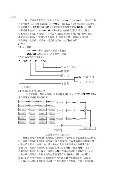
1. 概述浙江正泰仪表有限责任公司生产的DTSF666、DSSF666型三相电子式多费率电能表(以下简称电能表),符合GB/T17215-2002《1级和2级静止式交流有功电能表》、GB/T15284-2002《多费率电能表特殊要求》、DL/T614-1997《多功能电能表》、DL/T645-1997《多功能电能表通信规约》等电力行业标准对多费率表的各项要求;本产品可供计量参比频率为50Hz电网中的三相交流有功电能,并能进行多种费率和反向电能计量。
其特点是精度高、可靠性好、宽负荷、低功耗、误差曲线平直、抗干扰能力强。
2. 型号2.1 型号名称DTSF666三相四线电子式多费率电能表DSSF666三相三线电子式多费率电能表2.2 产品型号的组成及意义3. 工作原理3.1 电能计量单元工作原理电能表电能计量单元的核心是美国模拟器件公司生产的ADE7752芯片,本产品计量原理框图如图所示:被计量的每一相电能的电流通过互感器采样得到电压信号,再通过ADE7752 芯片内部的差放电路将电压信号放大,放大的信号经过A/D转换成与其成比例的数字信号,再经过高通滤波去除信号中的直流分量后进入数字乘法器的一个输入端。
被计量的电能电压信号经过电阻分压取样,通过ADE7752芯片内部的差放电路将信号放大,再经过A/D转换成与其成比例的数字信号,进入数字乘法器的另一个输入端与电流通道的信号进行乘法运算,完成被计量电能的瞬时功率测量。
每相输出瞬时功率通过数字低通滤波器,进行积分处理,然后进行绝对值累加后进入“数字/频率”转换器,经过分频电路输出的脉冲经过隔离后送入费率单元进行处理,记录总电量及费率电量。
3.2 费率单元工作原理电能计量单元输出的高频脉冲通过两个光电耦合器,一路作为无源脉冲输出用于出厂检验和用户对电能表进行校验;另一路送到CPU芯片进行数据处理。
CPU在系统(电能表程序)指令下,根据数据存储器中记忆的时段表及实时时钟判断当前的时段类型,并根据仪表常数计算出各个不同时段的电量值,再转存到内部存储器中,存储的数据既可以通过LCD显示,又可以通过红外和RS485两种通讯方式输出。
(带RS485通讯接口)1、概述正泰牌DDS666型单相电子式电能表系我厂最新产品,按GB/T17215-2002标准进行生产,用于测量额定频率为50Hz,参比电压为220V单相交流有功电能。
该产品采用计量电能的专用大规模集成电路和SMT技术,以确保计量准确度度和可靠性,为使停电后数据不丢失,使用步进电机计度器。
产品特点:产品全部采用性能稳定、功耗低的工业级元器件,运用工艺精心设计制造。
外壳采用阻燃聚碳酸酯,具有很强的抗机械冲击能力。
具有RS485通讯功能,通讯规约满足DL/T645-1997标准的要求。
型号规格产品型号为DDS666,规格见表1:表1使用环境条件温度范围规定的工作温度范围:-25℃~55℃;工作极限温度范围:-40℃~70℃。
相对湿度年平均小于75%时本机可正常工作。
安全性能本产品符合:GB/T 耐热和阻燃试验要求。
GB/T 17215-1998 规定的脉冲电压试验和交流电压试验要求。
GB/T 规定的静电放电抗扰度试验要求;GB/T 规定的高频电磁场抗扰度试验要求;GB/T 规定的快速瞬变脉冲群试验要求;GB/T 规定的雷击浪涌试验要求。
2.产品的结构特征与工作原理结构本产品的结构设计合理美观,工艺性好,维护方便。
表内功能板、和标牌全部经过合理的设计,采用了卡式安装,可靠方便;功能板是密封安装在有阻燃功能和较高的机械强度的外壳内,保证仪表在GB/T 17215-2002 标准规定的防尘和防水条件下,能够正常工作。
注:S+、S-为测试脉冲输出端,测试脉冲信号采用光耦隔离。
工作原理本机采用美国模拟器件公司(ADI)生产的ADE7755芯片计量单相有功电能,通过电阻分压网络和分流元件分别对电压信号和电流信号采样,送到ADE7755电能计量芯片,在ADE7755内部经过差分放大、A/D转换和乘法器电路进行乘法运算,完成被计量电能的瞬时功率测量;再通过低通滤波和“数字/频率”转换器,输出与被计量电能平均功率成比例的频率脉冲信号,其中高频脉冲输出可供校验使用,低频脉冲输出给计度器显示电量及CPU进行通讯抄收等数据处理;3、技术特性主要性能计量功能:本机可计量正、反向有功电能,反向电能按正向累计;输出功能本机采用无源隔离型电量脉冲输出接口,脉冲输出波形为方波;本机具有电量脉冲输出指示,采用红色LED指示;RS485通讯功能电能表可使用掌上电脑通过RS485通讯的方式对电能表进行表号设置、电量底度设置和抄收当前电量等功能。
DTSF666使用说明1.基本介绍:DTSF666是一款多功能设备,内置多种测试和实验功能。
它可以在物理、化学、生物和电子领域进行广泛的实验和测试。
它具有独立的操作系统和用户界面,使得操作简单方便。
2.开机操作:按下电源按钮以打开DTSF666、启动过程需要几秒钟,此时请耐心等待。
一旦启动完成,您将看到设备的主屏幕。
3.设备导航:DTSF666具有易于导航的用户界面。
主屏幕上显示有各种实验和测试选项。
使用方向键选择您想要执行的功能。
按下“确认”按钮进入该功能。
4.实验和测试功能:DTSF666包含多种实验和测试功能,如温度测量、物质分析、电路测试等。
每个功能都有详细的操作说明和参数设置选项。
请按照屏幕上的提示进行操作。
5.数据处理和分析:DTSF666还具有强大的数据处理和分析功能。
您可以将实验和测试数据导入设备,并使用内置的分析工具进行数据处理。
此外,您还可以将数据导出到其他设备或存储介质中,以便进行进一步的分析和处理。
6.外部设备连接:DTSF666支持与外部设备的连接,如计算机、打印机、传感器等。
您可以使用USB或其他适配器将外部设备连接到DTSF666,并与之进行数据交换和控制。
7.更新和维护:DTSF666的操作系统和软件可以进行更新和维护。
当有新的软件版本或修复程序发布时,您可以通过连接到互联网或使用外部存储设备进行更新。
总结:DTSF666是一款功能强大的设备,适用于各种实验和测试。
使用DTSF666之前,请阅读用户手册以了解详细的操作说明和安全注意事项。
请根据实际需要选择合适的实验和测试功能,并妥善保管实验数据。
希望DTSF666能为您的实验和测试工作带来便利和高效。
DTSU666-H 100 A and 250 A Smart Power SensorQuick GuideIssue: 02Date: 2019-08-30HUAWEI TECHNOLOGIES CO., LTD.1OverviewModel Naming ConventionsDTSU666-H 100 A/40 mA, DTSU666-H 250 A/50 mADTSU666-H 100 A/40 mA is abbreviated as DTSU666-H.AppearanceDifferences between DTSU666-H and DTSU666-H 250 A/50 mA:•Parameters on the panelDTSU666-H DTSU666-H 250 A/50 mAVoltage Input: 3×230/400 V or 3×400 VCurrent Transformer(CT): 100 A/40 mA or 250 A/50 mA;Category DTSU666-H DTSU666-H 250 A/50 mAData update period < 0.35s < 0.5s Measurement range 0–100 A 0–250 APower grid systemThree-phase four-wireThree-phase three-wire, three-phase four-wire•NameplateDTSU666-H DTSU666-H 250 A/50 mAAppearancePerformance and SpecificationPort Definition2Installing the DTSU666-H and DTSU666-H 250 A/50 mA3Installing the Cable1.Install the smart power sensor on the standard din rail of DIN35mm2.Install the Smart Power Sensor to the standard din rail from the top to the bottom, and then push the instrument to the din rail from the bottom to the front part.Cable Port Type Conductor Cross-sectional Area RangeOuter DiameterSourceAC power cableUa-3Four-core outdoor copper cable4-6 mm 210-21 mm Prepared by the customerUb-6Uc-9Un-10CT cableIA*-13///ManufacturerIA-14///IB*-16///IB-17///IC*-19///IC-21///Comm. cableRS485A-24Two-core outdoor shielded twisted pair0.25-1 mm 24-11 mm ManufacturerRS485B-25Prepare cablesWiring Diagram--Three Phase Four Wire Support model:•DTSU666-H•DTSU666-H 250 A/50 mAVoltage specifications:•Phase voltage: 176–288 V AC•Extended operating voltage:0.7–1.3 Un1.Three phase four wire: Connectthe Ua, Ub, Uc, Un voltage linesto the 3, 6, 9 and 10 terminals ofthe collector. Connect currenttransformer outlets IA*, IA, IB*, IB,IC*, IC to terminals 13, 14, 16, 17,19, 21 of the collector.2.Connect RS485A and RS485B tothe communication host.Wiring Diagram--Three Phase Three Wire Support model:•DTSU666-H 250 A/50 mAVoltage specifications:•Line voltage: 304–499 V AC•Extended operating voltage:0.7–1.3 Un1.Three phase three wire:Connect the Ua, Uc, Ubvoltage lines to the 3, 9 and10 terminals of the collector.Connect current transformeroutlets IA*, IA, IB*, IB, IC*, ICto terminals 13, 14, 16, 17,19, 21 of the collector.2.Connect RS485A andRS485B to thecommunication host.Display (Auto loop)No.Display interface Description No.Display interface Description1Imp. Activeenergy =10000.0 kWh2Exp. activeenergy= 2345.67 kWh3active power= 3.291 kW4Phase Avoltage= 220.0 V5Phase B voltage= 220.1 V6Phase Cvoltage= 220.20 V7Phase A current= 5.000 A8Phase Bcurrent= 5.001 A9Phase C current= 5.002 A10FrequencyFreq= 50.00Hz4User Interface Auto loop Switch time = 5s.No.Display interface Description No.Display interface Description1Comb. activeenergy= 7654.33 kWh2Imp. activeenergy= 10000.0 kWh3Exp. activeenergy= 2345.67 kWh4None Parity,1 Stop Bit,Baud = 9600bps5001 representsaddress6Phase Avoltage= 220.0 V7Phase Bvoltage= 220.1 V8Phase Cvoltage= 220.20 V9Phase Acurrent= 5.000 A10Phase Bcurrent= 5.001 A11Phase Ccurrent= 5.002 A12Phase activepower = 3.291kW13Phase A activepower = 1.090kW14Phase B activepower = 1.101kW15Phase C activepower= 1.100 kW16power factorPFt= 0.500 L17Phase A powerfactorPfa= 1.000 L18Phase B powerfactor PFb=0.500 L19Phase C powerfactor PFc=0.500 C20FrequencyFreq= 50.00HzComb. active energy = Imp. active energy -Exp. active energy Display (Change by key " ")ParameterParameter Value range Description1: 645; 2: n.2; 3: n.1; 4: E.1; 5: O.1;Settings for communication stop bit and Parity bits:1: Factory mode;2: None parity, 2 stop bits, n.2;3: None parity, 1 stop bit, n.1;4:Even parity, 1 stop bit, E.1;5:Odd parity, 1 stop bit, O.1;0: 4.800; 1: 9.600;Communication baud rate: 0: 4800 bps;1: 9600 bps;11–19Communication addressButton description: “SET” represents “confirmation” or “Cursor shift (when entering digits)” while “ESC” button represents “Exit”, "→" represents “add” Input code (default to be 701) Setup1.Check that all mounting brackets are securely installed and all screws are tightened.2.Check that all cables are reliably connected with correct polarity and no short circuit.For details, see DTSU666-H 100 A and 250 A Smart Power Sensor User Manual .6Verifying the Installation7Powering On the SystemFault phenomenonFactor analysisElimination methodNo display after the instrument being powered on1. Incorrect wiring mode.2. Abnormal voltage supplied for the instrument.1. If the wiring mode is incorrect, please connect based on the correct wiring mode (see the wiring diagram ).2. If the supplied voltage is abnormal, please supply the voltage on the instrument specification.Abnormal RS485 communication1. The RS485 communication cable is disconnected, short circuit or reversely connected.2. The address, baud rate, data bit and parity bit of theinstrument is not in accordance with the inverter.1. If any problems for the communication cable, please change the cable.2. Set the address, baud rate, data bit and parity bit of theinstrument to be the same as the inverter through buttons and so as the "parameter setting".Power metering inaccuracy1. Wrong wiring, please check whether the correspondingphase sequence of voltage and current is correct.2. Check whether the high & low end of current transformer inlet is reversely connected. Please observe the power, to beabnormal if any negative values.1. For wrong wiring, please connect based on the correct wiring mode (see the wiring diagram ).2. If a negative value isdisplayed, change the cable connection mode of the current transformer to ensure that the high and low ends are connected properly.Customer Service ContactRegion Country Service Support Email PhoneEurope France******************************0080033888888 GermanySpainItalyUKNetherlandsOther countries For details, see .Asia Pacific Australia******************************1800046639Turkey******************************-Malaysia********************0080021686868/1800220036Thailand(+66) 26542662 (charged bylocal call)1800290055 (free in Thailand) China***********************4008229999Other countries********************0060-3-21686868Japan Japan*******************.com0120258367 India India******************************180****8009South Korea South Korea*******************.com-North America USA******************************1-877-948-2934 Canada******************************1-855-482-9343Latin America Mexico******************************018007703456/0052-442-4288288 Argentina0-8009993456Brazil0-8005953456Chile800201866 (only for fixed) Other countries0052-442-4288288Middle East and Africa Egypt******************************************/0020235353900 UAE*********** South Africa0800222900 Saudi Arabia8001161177 Pakistan0092512800019 Morocco0800009900 Other countries0020235353900Huawei Technologies Co., Ltd. Huawei Industrial Base, Bantian, Longgang, Shenzhen 518129, People's Republic of China 。
1. 概述浙江正泰仪表有限责任公司生产的DTSF666、DSSF666型三相电子式多费率电能表(以下简称电能表),符合GB/T17215-2002《1级和2级静止式交流有功电能表》、GB/T15284-2002《多费率电能表特殊要求》、DL/T614-1997《多功能电能表》、DL/T645-1997《多功能电能表通信规约》等电力行业标准对多费率表的各项要求;本产品可供计量参比频率为50Hz电网中的三相交流有功电能,并能进行多种费率和反向电能计量。
其特点是精度高、可靠性好、宽负荷、低功耗、误差曲线平直、抗干扰能力强。
2. 型号2.1 型号名称DTSF666三相四线电子式多费率电能表DSSF666三相三线电子式多费率电能表2.2 产品型号的组成及意义3. 工作原理3.1 电能计量单元工作原理电能表电能计量单元的核心是美国模拟器件公司生产的ADE7752芯片,本产品计量原理框图如图所示:被计量的每一相电能的电流通过互感器采样得到电压信号,再通过ADE7752 芯片内部的差放电路将电压信号放大,放大的信号经过A/D转换成与其成比例的数字信号,再经过高通滤波去除信号中的直流分量后进入数字乘法器的一个输入端。
被计量的电能电压信号经过电阻分压取样,通过ADE7752芯片内部的差放电路将信号放大,再经过A/D转换成与其成比例的数字信号,进入数字乘法器的另一个输入端与电流通道的信号进行乘法运算,完成被计量电能的瞬时功率测量。
每相输出瞬时功率通过数字低通滤波器,进行积分处理,然后进行绝对值累加后进入“数字/频率”转换器,经过分频电路输出的脉冲经过隔离后送入费率单元进行处理,记录总电量及费率电量。
3.2 费率单元工作原理电能计量单元输出的高频脉冲通过两个光电耦合器,一路作为无源脉冲输出用于出厂检验和用户对电能表进行校验;另一路送到CPU芯片进行数据处理。
CPU在系统(电能表程序)指令下,根据数据存储器中记忆的时段表及实时时钟判断当前的时段类型,并根据仪表常数计算出各个不同时段的电量值,再转存到内部存储器中,存储的数据既可以通过LCD显示,又可以通过红外和RS485两种通讯方式输出。
DTSD666/DSSD666 型三相电子式多功能电能表DTSD666/DSSD666型三相电子式多功能电能表(以下简称电能表)采用大规模集成电路,应用数字采样技术,根据工业用户的用电管理需求进行设计、制造具有现代先进水平的电能计量产品,主要用于参比频率为50Hz(或60Hz)的三相电网中,对大、中型工商业用户及发、输、配电环节进行电能计量和电力质量监测。
1 产品概述2 主要功能及特点3 主要技术参数● 具有正反向有功、四象限无功电能计量和存储功能● 具有分时计量功能,即可按相应的时段分别累计、存储总、尖、峰、平、谷有功电能、无功电能● 能存储12个结算周期电量数据,结算时间可设定为每月中任何一天的整点时刻● 测量并存储双向最大需量、分时段最大需量及出现时间的日期和时间● 具有电压、电流、功率、功率因数、当前需量等实时参量测量功能● 具有定时、瞬时、约定、整点及日冻结功能,冻结特征字可设● 具有两套时区、时间表、可在约定的时刻自动转换● 具有红外、RS485通信接口,方便与外界交换数据● 具有电压异常、电流异常、掉电、清零、校时、编程、开表盖、开端钮等事件记录功能● 具有负荷曲线记录功能,可按用户设定的时间间隔对选定的六类数据进行滚动记录,间隔时间 可在1min~60min 间任意设置>> 精准计量 智慧物联 17>> 精准计量 智慧物联16DDZY666 型单相远程费控智能电能表(远程—开关内/外置)2 主要功能及特点3 主要技术参数备注:经互感器接入和最大电流超过60A 的电能表需要外配NB1S(带分励脱扣器,220V)实现通断 电功能。
● 具有正反向有功、组合有功电能计量功能,组合有功特征字可设● 具有分时计量功能,可按相应的时段分别累计、存储总、尖、峰、平、谷电能量,可以存储上12 个结算周期的总电能和各费率电能量● 时段费率功能:具有两套费率时区、时段表,可在约定的时刻自动转换● 具有定时、瞬时、约定、整点及日冻结功能,冻结数据模式字可设● 具有电压、电流、功率、功率因数、电网频率等实时参量测量功能● 具有掉电、事件清零、电表清零、校时、编程、开罩盖等事件记录● 具有红外通信、RS485通信接口,方便与外界交换数据● 电费计算在远程售电管理系统中完成,电能表可以通过RS485等虚拟介质接收远程售电管理系 统下发的拉闸、允许合闸、ESAM 数据抄读指令,指令需通过严格的密码验证及安全认证● 采用全自动软件校表技术,校表简单,速度快,准确度高● 采用罩盖和盖板的一体化设计,造型新颖,美观实用DDZY666型单相远程费控智能电能表是采用大规模集成电路,应用数字采样技术,根据智能电网“信息化、自动化、互动化”建设要求而设计制造的电能表,主要用于智能电网中单相居民用户的电能计量。
DTSU666 series three phase four wire electronic energy meter (Din-rail) DSSU666 series three phase three wire electronic energy meter (Din-rail)ManualZTY0.464.1002Zhejiang Chint Instrument & Meter Co., Ltd.Jan., 2018.1. Brief Introduction1.1 Main application & applicable rangeDTSU666 series three phase four wire and DSSU666 series three phase three wire electronic energy meter (din-rail) (hereinafter referred to as the “instrument”) is designed based on power monitoring and energy metering demands for electric power system, communication industry, construction industry, etc. as a new generation of intelligent instrument combining measurement and communication function, mainly applied into the measurement and display for the electric parameters in the electric circuit including three voltage, three current, active power, reactive power, frequency, positive& negative energy, four-quadrant energy, etc. Adopting the standard DIN35mm din rail mounting and modular design, it is characterized with small volume, easy installation and easy networking, widely applied into the internal energy monitoring and assessment for industrial and mining enterprises, hotels, schools, large public buildings.Complied standards:IEC 61010-1:2010《Safety requirements for electrical equipment for measurement,control and laboratory use Part1:General requirements》IEC 61326-1:2013 《Electrical equipment for measurement,control and laboratory use –EMC requirements Part1:General requirements》1.2 Product Features1)Characterized with positive and reverse active power, four quadrant reactive power meteringand storage function.2)RS485 communication interface, easy to exchange data with outside;3)Adopting the standard DIN35mm din rail mounting and modular design, it is characterizedwith small volume, easy installation and easy networking1.3 Model composition and meaningsTable 1 product model and specification1.4. Environmental conditions1.4. 1.Temperature rangeIndoor type:Regulated working temperature range: -10℃~+45℃;Limited working temperature range: -25℃~+75℃;1.4.2 Relative humidity(Annually average):≤75%;1.4.3 Atmospheric pressure: 63.0kPa~106.0kPa( altitude 4km and below), excepting the requirements for special orders.2. Main Technical Performance & Parameters2.1 Start and Defluction2.1.1. StartUnder the power factor of 1.0 and started current, the instrument can be started and continuously measure (for multiple phase instrument, it will bring balanced load). If the instrument is designed based on measurement for dual directional energy, then it is applicable for each direction of energy.Table 3 start current2.1.2. DefluctionWhen adding voltage while there is no current on the current circuit, the test output of the instrument shall not produce another pulse. When testing, the current circuit shall be opened, and the added voltage for voltage circuit shall be 115% of the referenced voltage.Shortest testing time Δt :For instrument of class 0.5S and class1: 6max60010Δt [min]n k m U I ⨯≥⋅⋅⋅ For instrument of class 2: 6max48010Δt [min]n k m U I ⨯≥⋅⋅⋅ From the formula, k represents meter constant (imp/kWh), m represents measuring components, Un represents referenced voltage (V) and Imax represents the maximized current (A). 2.2. Electrical parametersTable 3 Electrical parameters3.Main function 3.1. Displayed functionFrom the displayed interface, the electrical parameter and energy data are all primary side data (that is, the multiplied by current and voltage ratios). The energy measuring value will be displayedseven bits, with the displaying range from 0.00kWh to 9999999MWh.Diagram 1 Liquid crystal displayTable 4 Display interface3.2.Programming function3.2.1.Programming parameterTable 5 Programming parameter3.2.2.Programming operationButton description: “SET” button represents “confirmation”, or “cursor shift” (when input digits), “ESC” button represents “exit”, “→” button represents “add”. The input code is (default701).Diagram 2 Setting examples for current ratioDiagram 3 Setting examples for communication address and baud rateDiagram 4 Setting examples for zero electricity energymunication functionCharacterized with a RS485 communication interface, the baud rate can be changed between 1200bps, 2400bps, 4800bps and 9600bps. Communication protocol: complied with the requirement of DL/T645—2007 Multifunctional meter communication protocol or requirements of ModBus-RTU protocol.The default factory communication parameters are ModBus-RTU protocol, baud rate is 9600 bps, check bit and stop bit is n.1, table address is 1. The following table is the commonly used ModBus protocol address table. You can call for detailed communication protocol. The ModBus_RTU protocol reads 03H and writes the command 10H.4.Outline and installation sizeTable 6 Installation sizeDiagram 5 Outline size diagram (four modulus)5.Installation and operation manual5.1.Inspection TipsWhen unpacking the carton, if the shell has obvious signs caused by severe impact or falling, please contact with the supplier as soon as possible.After the instrument being removed from the packing box, it should be placed on a flat and safe plane, facing up, not overlaying for more than five layers. If not installed or used in a short time, the electric meter shall be packed and placed to the original packing box for storage.5.2.Installation and tips5.2.1.Installation and InspectionIf the model No or configuration in the original packing box is not in accordance with the requirement, please contact with the supplier. While, if the inner package or shell has been damaged after removing the instrument from the packing box, please do not install, power on the instrument, please contact with the supplier as soon as possible, instead.5.2.2.InstallationIt requires experienced electrician or professional personnel to install it and you must read this operation manual. During the installation, if the shell has obvious damage or marks caused by violent impact or falling, please do not install it or power on and contact with the supplier as soon as possible.5.3.Typical wiringThree phase four wire: direct connect Three phase three wire: direct connectDiagram 6 Diagram 7Three phase four wire: via current transformer Three phase three wire: via current transformer Diagram 8 Diagram 9RS485 Pulse outputDiagram 10 Diagram 11◆V oltage signal (only for connection via current transformer)2-------UA (Phase A voltage input terminal) 5 -------UB (Phase B voltage input terminal) 8-------UC (Phase C voltage input terminal) 11-------UN (Phase N voltage input terminal) ◆Current signal:1-------IA*(Phase A current input terminal) 3------IA (Phase A current output terminal)4-------IB*(Phase B current input terminal) 6------IB (Phase B current output terminal) 7-------IC*( Phase C current input terminal) 9------IC(Phase C current output terminal)◆RS485 Communication wire24-------A(RS485 Terminal A)25-------B(RS485 Terminal B)Auxiliary function19------ Active energy and reactive energy output high terminal21------ Active energy and reactive energy output low terminal6.Diagnosis, analysis and elimination for common faults7.Transportation & StorageWhen transporting and unpacking the products, please confirm they are not severely impacted, transporting and storing based on Transportation, basic environmental conditions and testing methods for instrument and meters of JB/T9329-1999.The instrument and accessories shall be stored in the dry and ventilated places, to avoid humidity and corrosive gas erosion, with the limited environmental temperature for storage to be 0℃~+40℃and relative humidity not exceeding 85%.8.Maintenance & ServiceWe guarantee free reparation and change for the multi-meter if found any unconformity with the standard, under circumstance of that the users fully comply with this instructions and complete seal after delivery within 18 months.Dear clients,Please assist us: when the product life is end, to protect our environment, please recycle the product or components, while for the materials that cannot be recycled, please also deal with it in a proper way. Really appreciate your cooperation and support.Name of Company: Zhejiang Chint Instrument & Meter Co., Ltd.Address: Wenzhou Bridge Industrial Zone, Yueqing, Zhejiang, China.Zip Code:325603Telephone:*************Fax:*************Service hotline: 4008177777FakeComplaint**************Website: http: //Email:ztyb@Date of Issue: January, 2018.No.:ZTY0.464.1002V1。
1. 概述浙江正泰仪表有限责任公司生产的DTSF666、DSSF666型三相电子式多费率电能表(以下简称电能表),符合GB/T17215-2002《1级和2级静止式交流有功电能表》、GB/T15284-2002《多费率电能表特殊要求》、DL/T614-1997《多功能电能表》、DL/T645-1997《多功能电能表通信规约》等电力行业标准对多费率表的各项要求;本产品可供计量参比频率为50Hz电网中的三相交流有功电能,并能进行多种费率和反向电能计量。
其特点是精度高、可靠性好、宽负荷、低功耗、误差曲线平直、抗干扰能力强。
2. 型号2.1 型号名称DTSF666三相四线电子式多费率电能表DSSF666三相三线电子式多费率电能表2.2 产品型号的组成及意义3. 工作原理3.1 电能计量单元工作原理电能表电能计量单元的核心是美国模拟器件公司生产的ADE7752芯片,本产品计量原理框图如图所示:被计量的每一相电能的电流通过互感器采样得到电压信号,再通过ADE7752 芯片内部的差放电路将电压信号放大,放大的信号经过A/D转换成与其成比例的数字信号,再经过高通滤波去除信号中的直流分量后进入数字乘法器的一个输入端。
被计量的电能电压信号经过电阻分压取样,通过ADE7752芯片内部的差放电路将信号放大,再经过A/D转换成与其成比例的数字信号,进入数字乘法器的另一个输入端与电流通道的信号进行乘法运算,完成被计量电能的瞬时功率测量。
每相输出瞬时功率通过数字低通滤波器,进行积分处理,然后进行绝对值累加后进入“数字/频率”转换器,经过分频电路输出的脉冲经过隔离后送入费率单元进行处理,记录总电量及费率电量。
3.2 费率单元工作原理电能计量单元输出的高频脉冲通过两个光电耦合器,一路作为无源脉冲输出用于出厂检验和用户对电能表进行校验;另一路送到CPU芯片进行数据处理。
CPU在系统(电能表程序)指令下,根据数据存储器中记忆的时段表及实时时钟判断当前的时段类型,并根据仪表常数计算出各个不同时段的电量值,再转存到内部存储器中,存储的数据既可以通过LCD显示,又可以通过红外和RS485两种通讯方式输出。
4.技术指标·参比频率:50Hz;·参比电压:三相四线3×220/380V、3×57.7/100V;三相三线3×380V、3×100V·电流规格:经互感器接入式3×1.5(6)A、3×3(6)A直接接入式3×5(20)A、3×10(40)A、3×15(60)A、3×20(80)A、3×30(100)A;(可按用户要求做)·仪表常数:100imp/kWh-3200 imp/kWh(以铭牌标注为准);·准确度等级:1级、2级;·起动在参比电压、参比频率及COSφ=1.0的条件下,直接接入式负载电流为0.004Ib(1级)或0.005Ib(2级),经互感器接入式负载电流为0.002In(1级)或0.003In(2级)电能表能起动并开始连续计量电能。
·潜动具有逻辑防潜动功能,电压回路加参比电压115%,电流回路断开的情况下,电能表不产生多于一个脉冲输出。
·气候条件·电气参数5. 尺寸及重量5.1 外形及安装尺寸图5.2 外形尺寸:256×166×79mm;安装尺寸:241×150mm5.3 重量约1.8kg6. 安装使用·安装电能表需有经验的电工或专业人员,并确定已经读完本手册;·从包装箱中取出电能表,确认外壳无损伤,检查包装箱中的物品是否和清单中的吻合;·电能表上部有挂钩螺钉孔,用M4挂钩螺钉固定,电能表下部有两个安装孔,用M4×10或M4×12自攻螺钉固定在墙壁或接线板上(见外形尺寸图);·检查两端的铅封是否完好;·电能表应按接线端盖上的接线图正确接线,18、19端为脉冲测试输出端,16、17端为RS485通讯接口端;·脉冲测试口示意图·外形示意图·接线图7.主要功能7.1 通讯功能:7.1.1 电能表具有红外和485两种通讯方式,通讯规符合DL/T645-1997《多功表通讯规约》和《辽宁省电力公司单相复费率电能表通讯规约》;7.1.2 对电能表进行编程前必须首先按下编程按钮,待打开编程开关后,输入正确的密码才能进行编程;7.1.3 当电能表进行通讯时,液晶上会显示“通讯”;7.2 计量功能:7.2.1 能够计量正向、反相有功总电能以及尖、峰、平、谷分时电能,反相电能同时按正相计量;7.2.2 具有需量计量功能,能够计量总、尖、峰、平、谷需量以及以及需量发生时间;7.2.3 电能表能够保存正相12个月的历史电量和3个月的历史需量;7.2.4 电量和需量通过手掌机可以单相抄收也可以块抄收;7.3 指示灯当有电量脉冲信号时,点亮脉冲指示灯80±20ms;7.4 时段和费率7.4.1 电能表可以最多可设置2套年时区,4个费率,8个时段;7.4.2 电能表内部定义尖对应费率1,峰对应费率2,平对应费率3,谷对应费率4;7.4.3 电能表能够根据当前的时钟准确的判断当前的时段表和费率;7.5 时钟和电池7.5.1 电能表采用硬件时钟电路,内置2000~2099年的百年历,能够自动计算闰年、闰月和星期;7.5.2 停电后由电池维持时钟正常工作;7.5.3 电能表采用3.6V、1.2Ah的高容量环保锂电池,正常应用寿命为10年;7.6 显示功能:7.6.1 轮显显示:电能表可以设置轮显显示项目(不超过16项),加电后,电表会根据设置的轮显项目和时间来轮流显示数据。
显示时首先显示代码,然后显示内容,同时还有中文提示;7.6.2 按键显示:电能表可以设置按键显示项目(不超过30项),通过按动翻页按键,电能表按预先设置的键显内容显示数据。
显示也是先显示代码,后显示内容。
如果不按动按键电表会自动进入轮显;7.6.3 电能表也可以通过手掌机中的“显示按键”命令对液晶键显内容进行翻页;7.6.4 提示显示7.6.4.1 失压时,报警符号和相应的相代号点亮;如C相失压,“LC”“”符号点亮;7.6.4.2 电池故障时,“”符号点亮;7.6.4.3 反向用电时,“”符号点亮;7.6.4.4 与电能表进行通讯时,“通讯”符号点亮;7.6.4.5 允许编程时,“”符号点亮;7.7 事件记录7.7.1 状态字:电能表能在状态字中记录存储器故障、时钟故障、电池电压低、电流反相等故障,01表示存储器故障;02表示时钟故障;08表示电池电压低;10表示电流反相;状态字可以液晶显示屏或通过通讯命令读出;7.7.2 电能表还可以记录以下事件:编程次数和最近一次的编程时间;总清次数和最近一次的总清时间;最近10次电流反相起始时间和结束时间;最近10次停电起始时间和结束时间。
7.8 校时:7.8.1 在编程开关打开、密码正确的条件下可以任意修改电能表的时钟;7.8.2 电能表还提供无密码校时功能,可在5分钟的范围内校正电能表的时钟;如果校时成功,电能表将在一个抄表周期( 20天)内屏蔽校时功能;7.9 密码:电能表有0级和1级密码,0级为最高权限密码,1级为编程密码;0级密可以修改1级密码,但1级密码不能修改0级密码;7.10 自动抄表日和需清7.10.1 在指定的自动抄表日电表会进行自动需清,将电量和需量记录自动转存;7.10.2 另外电能表还提供手动需清方式。
在编程状态下,按下翻页按键,持续5秒钟以上,待编程符号褪去不显或由手掌机发出“需量手动复位”命令;7.10.3 需量操作按如下次序进行:将当月的最大需量及发生时间、当月电量记录均滚入上月,并且把当前的最大需量和发生时间清零;7.11 总清零在编程开关打开、密码正确的状态下,由手掌机发出“电表清零”命令,可以清除全部电量和用电事件。
8 运输与贮存·产品运输和拆封时不应受到剧烈冲击,根据JB/T9329-1999《仪器仪表运输、贮存基本环境条件及试验方法》的规定运输和贮存。
·在搬运、取用、安装过程中受到剧烈撞击或高空跌落造成外壳有明显损毁痕迹时,请不要对该表加电,并尽快联络供应商。
·如果在短时间内不安装使用,请将表包装好放回原包装箱收藏。
·保存、安装地点周围尽量避免有化学物品泄露或高频电磁辐射干扰。
·保存地点环境温度应为0~40℃,相对湿度不超过85%。
且在空气中不含有足以引起腐蚀的有害物质。
·原包装箱中缺少物品清单中所列对象或不符时,请与供应商联络。
·由原包装箱中取出时发现内包装或外壳损伤,不要对该表进行安装、加电,请与本公司售后服务部门联系。
·从包装箱中取出后,应放置于平坦、安全的平面,正面向上,不应叠放超过5层。
9 保修与服务自发货之日起18个月内,如用户发现不符合上述特性及技术数据要求,且在我公司检验铅封未动(或由有关电力计量部门证明)又完全遵守国家标准GB/T 15284及本说明书中所规定的运输、保存、安装及使用规则的条件下,出现质量问题,我公司负责免费维修或更换。
如果对本手册内容有疑问或异议,请与本公司售后服务部门联系。
本手册内容如有更改恕不另行通知。
尊敬的顾客请你们协助我们一件事,当本产品在其寿命终了时,为了保护我们的环境,请做好产品或其零部件的回收工作,对不能回收的材料,也请做好处理,非常感谢您的合作和支持。
附录:显示的数据及其标识附录:显示的数据及其标识。