管道设计说明书
- 格式:pdf
- 大小:1.53 MB
- 文档页数:31
SOLIDWORKSSOLIDWORKS Routing: Piping and TubingDassault Systèmes SolidWorks Corporation175 Wyman StreetWaltham, MA 02451 U.S.A.© 1995-2022, Dassault Systemes SolidWorks Corporation, a Dassault Systèmes SE company, 175 Wyman Street, Waltham, Mass. 02451 USA. All Rights Reserved.The information and the software discussed in this document are subject to change without notice and are not commitments by Dassault Systemes SolidWorks Corporation (DS SolidWorks).No material may be reproduced or transmitted in any form or by any means, electronically or manually, for any purpose without the express written permission of DS SolidWorks.The software discussed in this document is furnished under a license and may be used or copied only in accordance with the terms of the license. All warranties given by DS SolidWorks as to the software and documentation are set forth in the license agreement, and nothing stated in, or implied by, this document or its contents shall be considered or deemed a modification or amendment of any terms, including warranties, in the license agreement.For a full list of the patents, trademarks, and third-party software contained in this release, please go to the Legal Notices in the SOLIDWORKS documentation.Restricted RightsThis clause applies to all acquisitions of Dassault Systèmes Offerings by or for the United States federal government, or by any prime contractor or subcontractor (at any tier) under any contract, grant, cooperative agreement or other activity with the federal government. The software, documentation and any other technical data provided hereunder is commercial in nature and developed solely at private expense. The Software is delivered as "Commercial Computer Software" as defined in DFARS 252.227-7014 (June 1995) or as a "Commercial Item" as defined in FAR 2.101(a) and as such is provided with only such rights as are provided in Dassault Systèmes standard commercial end user license agreement. Technical data is provided with limited rights only as provided in DFAR 252.227-7015 (Nov. 1995) or FAR 52.227-14 (June 1987), whichever is applicable. The terms and conditions of the Dassault Systèmes standard commercial end user license agreement shall pertain to the United States government's use and disclosure of this software, and shall supersede any conflicting contractual terms and conditions. If the DS standard commercial license fails to meet the United States government's needs or is inconsistent in any respect with United States Federal law, the United States government agrees to return this software, unused, to DS. The following additional statement applies only to acquisitions governed by DFARS Subpart 227.4 (October 1988): "Restricted Rights - use, duplication and disclosure by the Government is subject to restrictions as set forth in subparagraph (c)(l)(ii) of the Rights in Technical Data and Computer Software clause at DFARS 252-227-7013 (Oct. 1988)."In the event that you receive a request from any agency of the U.S. Government to provide Software with rights beyond those set forth above, you will notify DS SolidWorks of the scope of the request and DS SolidWorks will have five (5) business days to, in its sole discretion, accept or reject such request. Contractor/ Manufacturer: Dassault Systemes SolidWorks Corporation, 175 Wyman Street, Waltham, Massachusetts 02451 USA.Document Number: PMT2312-ENGContents IntroductionAbout This Course . . . . . . . . . . . . . . . . . . . . . . . . . . . . . . . . . . . . . . . . 2Prerequisites . . . . . . . . . . . . . . . . . . . . . . . . . . . . . . . . . . . . . . . . . . 2Course Design Philosophy . . . . . . . . . . . . . . . . . . . . . . . . . . . . . . . 2Using this Book . . . . . . . . . . . . . . . . . . . . . . . . . . . . . . . . . . . . . . . 2About the Training Files. . . . . . . . . . . . . . . . . . . . . . . . . . . . . . . . . 3Conventions Used in this Book . . . . . . . . . . . . . . . . . . . . . . . . . . . 4Windows. . . . . . . . . . . . . . . . . . . . . . . . . . . . . . . . . . . . . . . . . . . . . . . . 4Use of Color . . . . . . . . . . . . . . . . . . . . . . . . . . . . . . . . . . . . . . . . . . . . . 5Graphics and Graphics Cards. . . . . . . . . . . . . . . . . . . . . . . . . . . . . 5Color Schemes . . . . . . . . . . . . . . . . . . . . . . . . . . . . . . . . . . . . . . . . 5More SOLIDWORKS Training Resources. . . . . . . . . . . . . . . . . . . . . . 6Local User Groups . . . . . . . . . . . . . . . . . . . . . . . . . . . . . . . . . . . . . 6 Lesson 1:Fundamentals of RoutingWhat is Routing? . . . . . . . . . . . . . . . . . . . . . . . . . . . . . . . . . . . . . . . . . 8Review Lesson . . . . . . . . . . . . . . . . . . . . . . . . . . . . . . . . . . . . . . . . 8Types of Routes . . . . . . . . . . . . . . . . . . . . . . . . . . . . . . . . . . . . . . . 8Routes. . . . . . . . . . . . . . . . . . . . . . . . . . . . . . . . . . . . . . . . . . . . . . . 9Routing FeatureManager . . . . . . . . . . . . . . . . . . . . . . . . . . . . . . . 10External vs. Virtual Files . . . . . . . . . . . . . . . . . . . . . . . . . . . . . . . 10Virtual Components . . . . . . . . . . . . . . . . . . . . . . . . . . . . . . . . . . . 10File Names in Routing . . . . . . . . . . . . . . . . . . . . . . . . . . . . . . . . . 11iContents SOLIDWORKSii Routing Setup. . . . . . . . . . . . . . . . . . . . . . . . . . . . . . . . . . . . . . . . . . . 15 Routing Add-in. . . . . . . . . . . . . . . . . . . . . . . . . . . . . . . . . . . . . . . 15 Routing Training Files . . . . . . . . . . . . . . . . . . . . . . . . . . . . . . . . . 15 Routing Library Manager. . . . . . . . . . . . . . . . . . . . . . . . . . . . . . . . . . 16 Routing File Locations and Settings. . . . . . . . . . . . . . . . . . . . . . . 17 General Routing Settings . . . . . . . . . . . . . . . . . . . . . . . . . . . . . . . . . . 18Lesson 2:Piping RoutesPiping Routes . . . . . . . . . . . . . . . . . . . . . . . . . . . . . . . . . . . . . . . . . . . 22Typical Piping Route . . . . . . . . . . . . . . . . . . . . . . . . . . . . . . . . . . 22Route Sketch. . . . . . . . . . . . . . . . . . . . . . . . . . . . . . . . . . . . . . . . . 23Pipes and Piping Components . . . . . . . . . . . . . . . . . . . . . . . . . . . . . . 24Pipes . . . . . . . . . . . . . . . . . . . . . . . . . . . . . . . . . . . . . . . . . . . . . . . 24End Components. . . . . . . . . . . . . . . . . . . . . . . . . . . . . . . . . . . . . . 24In Line Components . . . . . . . . . . . . . . . . . . . . . . . . . . . . . . . . . . . 24Other Types. . . . . . . . . . . . . . . . . . . . . . . . . . . . . . . . . . . . . . . . . . 25Routing Assembly Templates. . . . . . . . . . . . . . . . . . . . . . . . . . . . . . . 26Creating a Custom Routing Assembly Template. . . . . . . . . . . . . 26Selecting a Routing Assembly Template . . . . . . . . . . . . . . . . . . . 27Creating a Piping Route . . . . . . . . . . . . . . . . . . . . . . . . . . . . . . . . . . . 27Route Properties Dialog . . . . . . . . . . . . . . . . . . . . . . . . . . . . . . . . 28Auto Route . . . . . . . . . . . . . . . . . . . . . . . . . . . . . . . . . . . . . . . . . . . . . 33Route Specification Templates. . . . . . . . . . . . . . . . . . . . . . . . . . . . . . 34Creating Route Specification Templates . . . . . . . . . . . . . . . . . . . 35Using Route Specification Templates. . . . . . . . . . . . . . . . . . . . . . 36Exercise 1: Creating Templates . . . . . . . . . . . . . . . . . . . . . . . . . . . . . 37Exercise 2: Multiple Piping Routes 1. . . . . . . . . . . . . . . . . . . . . . . . . 38 Lesson 3:Advanced Piping RoutesAdvanced Piping Routes. . . . . . . . . . . . . . . . . . . . . . . . . . . . . . . . . . . 42Adding Alternate Elbows . . . . . . . . . . . . . . . . . . . . . . . . . . . . . . . 50Editing a Route. . . . . . . . . . . . . . . . . . . . . . . . . . . . . . . . . . . . . . . . . . 53Using the Route Along Relation. . . . . . . . . . . . . . . . . . . . . . . . . . 53Isolate Options . . . . . . . . . . . . . . . . . . . . . . . . . . . . . . . . . . . . . . . 55Using Piping Hangers. . . . . . . . . . . . . . . . . . . . . . . . . . . . . . . . . . 57Routing Along Existing Geometry. . . . . . . . . . . . . . . . . . . . . . . . . . . 59Exercise 3: Multiple Piping Routes 2. . . . . . . . . . . . . . . . . . . . . . . . . 64SOLIDWORKS Contents Lesson 4:Piping FittingsPiping Fittings. . . . . . . . . . . . . . . . . . . . . . . . . . . . . . . . . . . . . . . . . . . 70Drag and Drop a Fitting . . . . . . . . . . . . . . . . . . . . . . . . . . . . . . . . . . . 70Using Planes in Routes. . . . . . . . . . . . . . . . . . . . . . . . . . . . . . . . . 73Split Route to Add Fittings. . . . . . . . . . . . . . . . . . . . . . . . . . . . . . 73Orienting In Line Fittings. . . . . . . . . . . . . . . . . . . . . . . . . . . . . . . 74Adding Tees at Junctions . . . . . . . . . . . . . . . . . . . . . . . . . . . . . . . 76Remove Tube/Pipe . . . . . . . . . . . . . . . . . . . . . . . . . . . . . . . . . . . . 77Creating Custom Fittings . . . . . . . . . . . . . . . . . . . . . . . . . . . . . . . . . . 81Replacing Piping Fittings . . . . . . . . . . . . . . . . . . . . . . . . . . . . . . . 83Add Fitting . . . . . . . . . . . . . . . . . . . . . . . . . . . . . . . . . . . . . . . . . . 84Coverings . . . . . . . . . . . . . . . . . . . . . . . . . . . . . . . . . . . . . . . . . . . 87Exercise 4: Piping Fittings . . . . . . . . . . . . . . . . . . . . . . . . . . . . . . . . . 91Exercise 5: Piping on a Frame . . . . . . . . . . . . . . . . . . . . . . . . . . . . . . 93 Lesson 5:Tubing RoutesTubing Routes. . . . . . . . . . . . . . . . . . . . . . . . . . . . . . . . . . . . . . . . . . . 96Typical Tubing Route. . . . . . . . . . . . . . . . . . . . . . . . . . . . . . . . . . 96Tubes and Tubing Components . . . . . . . . . . . . . . . . . . . . . . . . . . . . . 97Tubes. . . . . . . . . . . . . . . . . . . . . . . . . . . . . . . . . . . . . . . . . . . . . . . 97Terminal Components. . . . . . . . . . . . . . . . . . . . . . . . . . . . . . . . . . 97In Line Components . . . . . . . . . . . . . . . . . . . . . . . . . . . . . . . . . . . 97Flexible Tubing with Auto Route . . . . . . . . . . . . . . . . . . . . . . . . . . . . 98Orthogonal Tubing Routes with Auto Route . . . . . . . . . . . . . . . . . . . 99Orthogonal Tubing Solutions . . . . . . . . . . . . . . . . . . . . . . . . . . . 100Bend and Spline Errors. . . . . . . . . . . . . . . . . . . . . . . . . . . . . . . . . . . 101Bend Radius Too Small . . . . . . . . . . . . . . . . . . . . . . . . . . . . . . . 102Export Pipe/Tube Data . . . . . . . . . . . . . . . . . . . . . . . . . . . . . . . . 103Using Envelopes to Represent Volumes. . . . . . . . . . . . . . . . . . . 104Start Route and Add to Route. . . . . . . . . . . . . . . . . . . . . . . . . . . 105Routings Tubes Through Clips. . . . . . . . . . . . . . . . . . . . . . . . . . 107Repairing Bend Errors . . . . . . . . . . . . . . . . . . . . . . . . . . . . . . . . 109Flip Direction . . . . . . . . . . . . . . . . . . . . . . . . . . . . . . . . . . . . . . . 110Repair Route. . . . . . . . . . . . . . . . . . . . . . . . . . . . . . . . . . . . . . . . 110Re-route Spline. . . . . . . . . . . . . . . . . . . . . . . . . . . . . . . . . . . . . . 111Select Using Envelope . . . . . . . . . . . . . . . . . . . . . . . . . . . . . . . . 112Route Segment Properties. . . . . . . . . . . . . . . . . . . . . . . . . . . . . . 115Tubing Drawings . . . . . . . . . . . . . . . . . . . . . . . . . . . . . . . . . . . . . . . 116Rename. . . . . . . . . . . . . . . . . . . . . . . . . . . . . . . . . . . . . . . . . . . . 116Save to External File. . . . . . . . . . . . . . . . . . . . . . . . . . . . . . . . . . 116Exercise 6: Orthogonal Tubing Routes. . . . . . . . . . . . . . . . . . . . . . . 119Exercise 7: Flexible Tubing Routes . . . . . . . . . . . . . . . . . . . . . . . . . 123Exercise 8: Orthogonal and Flexible Tubing Routes . . . . . . . . . . . . 127iiiContents SOLIDWORKS Lesson 6:Piping and Tubing ChangesPiping and Tubing Changes . . . . . . . . . . . . . . . . . . . . . . . . . . . . . . . 132Procedures for Tubing and Piping . . . . . . . . . . . . . . . . . . . . . . . 132Change Route Diameter . . . . . . . . . . . . . . . . . . . . . . . . . . . . . . . 133A Note About Dimensioning Route Geometry. . . . . . . . . . . . . . 138Custom Pipe/Tube Configurations . . . . . . . . . . . . . . . . . . . . . . . 140Pipe Penetrations. . . . . . . . . . . . . . . . . . . . . . . . . . . . . . . . . . . . . . . . 141Flange to Flange Connections. . . . . . . . . . . . . . . . . . . . . . . . . . . . . . 143Pipe Spools. . . . . . . . . . . . . . . . . . . . . . . . . . . . . . . . . . . . . . . . . . . . 144Spools in Drawings. . . . . . . . . . . . . . . . . . . . . . . . . . . . . . . . . . . 147Using Gaskets. . . . . . . . . . . . . . . . . . . . . . . . . . . . . . . . . . . . . . . 147Copying Routes. . . . . . . . . . . . . . . . . . . . . . . . . . . . . . . . . . . . . . . . . 148Mating Routes. . . . . . . . . . . . . . . . . . . . . . . . . . . . . . . . . . . . . . . 148Adding Slope . . . . . . . . . . . . . . . . . . . . . . . . . . . . . . . . . . . . . . . . . . 151Editing and Removing the Slope . . . . . . . . . . . . . . . . . . . . . . . . 151Editing Piping Routes. . . . . . . . . . . . . . . . . . . . . . . . . . . . . . . . . . . . 153Using Threaded Pipe and Fittings. . . . . . . . . . . . . . . . . . . . . . . . 153Deleting and Editing Route Geometry . . . . . . . . . . . . . . . . . . . . 154Editing for Obstructions . . . . . . . . . . . . . . . . . . . . . . . . . . . . . . . . . . 158Moving Fittings With the Triad . . . . . . . . . . . . . . . . . . . . . . . . . 158Using Guidelines with Pipe Routes . . . . . . . . . . . . . . . . . . . . . . 159Guideline Actions. . . . . . . . . . . . . . . . . . . . . . . . . . . . . . . . . . . . 159Piping Drawings. . . . . . . . . . . . . . . . . . . . . . . . . . . . . . . . . . . . . . . . 161Pipe Drawing . . . . . . . . . . . . . . . . . . . . . . . . . . . . . . . . . . . . . . . 161Drawing Tools . . . . . . . . . . . . . . . . . . . . . . . . . . . . . . . . . . . . . . 161Exercise 9: Create and Edit Threaded Pipe Routes . . . . . . . . . . . . . 168Exercise 10: Using Pipe Spools . . . . . . . . . . . . . . . . . . . . . . . . . . . . 174 Lesson 7:Creating Routing ComponentsRouting Library Parts . . . . . . . . . . . . . . . . . . . . . . . . . . . . . . . . . . . . 176Libraries . . . . . . . . . . . . . . . . . . . . . . . . . . . . . . . . . . . . . . . . . . . . . . 176Piping . . . . . . . . . . . . . . . . . . . . . . . . . . . . . . . . . . . . . . . . . . . . . 176Threaded Piping . . . . . . . . . . . . . . . . . . . . . . . . . . . . . . . . . . . . . 180Tubing. . . . . . . . . . . . . . . . . . . . . . . . . . . . . . . . . . . . . . . . . . . . . 181Assembly Fittings. . . . . . . . . . . . . . . . . . . . . . . . . . . . . . . . . . . . 182Cable Trays. . . . . . . . . . . . . . . . . . . . . . . . . . . . . . . . . . . . . . . . . 182Electrical Ducting. . . . . . . . . . . . . . . . . . . . . . . . . . . . . . . . . . . . 183miscellaneous fittings. . . . . . . . . . . . . . . . . . . . . . . . . . . . . . . . . 183HVAC. . . . . . . . . . . . . . . . . . . . . . . . . . . . . . . . . . . . . . . . . . . . . 184HVAC. . . . . . . . . . . . . . . . . . . . . . . . . . . . . . . . . . . . . . . . . . . . . 184 ivSOLIDWORKS ContentsCreating Routing Library Parts. . . . . . . . . . . . . . . . . . . . . . . . . . . . . 185Pipe and Tube Components . . . . . . . . . . . . . . . . . . . . . . . . . . . . . . . 185Pipe vs. Tube Components. . . . . . . . . . . . . . . . . . . . . . . . . . . . . 185Copying Routing Components . . . . . . . . . . . . . . . . . . . . . . . . . . . . . 186Creating a Pipe Using Copy and Edit. . . . . . . . . . . . . . . . . . . . . 186Routing Library Manager. . . . . . . . . . . . . . . . . . . . . . . . . . . . . . . . . 188Routing Component Wizard. . . . . . . . . . . . . . . . . . . . . . . . . . . . 188Fitting Components. . . . . . . . . . . . . . . . . . . . . . . . . . . . . . . . . . . . . . 192Using the Routing Component Wizard. . . . . . . . . . . . . . . . . . . . 192Routing Functionality Points . . . . . . . . . . . . . . . . . . . . . . . . . . . . . . 193Connection Points. . . . . . . . . . . . . . . . . . . . . . . . . . . . . . . . . . . . 193Routing Points. . . . . . . . . . . . . . . . . . . . . . . . . . . . . . . . . . . . . . . 193Routing Geometry. . . . . . . . . . . . . . . . . . . . . . . . . . . . . . . . . . . . . . . 194Part Validity Check. . . . . . . . . . . . . . . . . . . . . . . . . . . . . . . . . . . . . . 195Excel Design Table. . . . . . . . . . . . . . . . . . . . . . . . . . . . . . . . . . . 195Design Table Check . . . . . . . . . . . . . . . . . . . . . . . . . . . . . . . . . . . . . 196Component Attributes. . . . . . . . . . . . . . . . . . . . . . . . . . . . . . . . . . . . 197Configuration Properties. . . . . . . . . . . . . . . . . . . . . . . . . . . . . . . 197Part Properties. . . . . . . . . . . . . . . . . . . . . . . . . . . . . . . . . . . . . . . 197Elbow Components. . . . . . . . . . . . . . . . . . . . . . . . . . . . . . . . . . . . . . 198Valve Components . . . . . . . . . . . . . . . . . . . . . . . . . . . . . . . . . . . . . . 202Assembly Routing Components. . . . . . . . . . . . . . . . . . . . . . . . . 202Equipment. . . . . . . . . . . . . . . . . . . . . . . . . . . . . . . . . . . . . . . . . . 204Exercise 11: Creating and Using Equipment . . . . . . . . . . . . . . . . . . 210 Lesson 8:Electrical Ducting, Cable Tray, and HVAC RoutesElectrical Ducting, Cable Tray, and HV AC Routes . . . . . . . . . . . . . 216Electrical Ducting, Cable Tray and HVAC Components. . . . . . 216Rectangular and Circular Components. . . . . . . . . . . . . . . . . . . . 218Modifying a Routing Library Part . . . . . . . . . . . . . . . . . . . . . . . 219Electrical Ducting Routes. . . . . . . . . . . . . . . . . . . . . . . . . . . . . . . . . 220Cable Tray Routes. . . . . . . . . . . . . . . . . . . . . . . . . . . . . . . . . . . . . . . 224Routing Component Orientation. . . . . . . . . . . . . . . . . . . . . . . . . 225HV AC Routes . . . . . . . . . . . . . . . . . . . . . . . . . . . . . . . . . . . . . . . . . . 228Components . . . . . . . . . . . . . . . . . . . . . . . . . . . . . . . . . . . . . . . . 228Coverings . . . . . . . . . . . . . . . . . . . . . . . . . . . . . . . . . . . . . . . . . . 229In Line Duct Components. . . . . . . . . . . . . . . . . . . . . . . . . . . . . . 231Transition to Circular HVAC Routes. . . . . . . . . . . . . . . . . . . . . 232HVAC and Ducting Drawings . . . . . . . . . . . . . . . . . . . . . . . . . . 233Exercise 12: Electrical Ducting Routes . . . . . . . . . . . . . . . . . . . . . . 236vContents SOLIDWORKS Lesson 9:Using SOLIDWORKS ContentUsing SOLIDWORKS Content . . . . . . . . . . . . . . . . . . . . . . . . . . . . 240Adding Content. . . . . . . . . . . . . . . . . . . . . . . . . . . . . . . . . . . . . . 240Content Files. . . . . . . . . . . . . . . . . . . . . . . . . . . . . . . . . . . . . . . . 242Custom Library Naming. . . . . . . . . . . . . . . . . . . . . . . . . . . . . . . 245Virtual Clips . . . . . . . . . . . . . . . . . . . . . . . . . . . . . . . . . . . . . . . . 246Components Used in the Routes. . . . . . . . . . . . . . . . . . . . . . . . . 247Exercise 13: Using SOLIDWORKS Content. . . . . . . . . . . . . . . . . . 253 Appendix A:Review SectionReview of Configurations. . . . . . . . . . . . . . . . . . . . . . . . . . . . . . . . . 258How Routing Uses Configurations. . . . . . . . . . . . . . . . . . . . . . . 258A Note About File References . . . . . . . . . . . . . . . . . . . . . . . . . . . . . 259Find References . . . . . . . . . . . . . . . . . . . . . . . . . . . . . . . . . . . . . 259Pack and Go . . . . . . . . . . . . . . . . . . . . . . . . . . . . . . . . . . . . . . . . 259File Management . . . . . . . . . . . . . . . . . . . . . . . . . . . . . . . . . . . . 259How Libraries Use Configurations. . . . . . . . . . . . . . . . . . . . . . . 260Design Tables . . . . . . . . . . . . . . . . . . . . . . . . . . . . . . . . . . . . . . . . . . 260Design Table Input and Output. . . . . . . . . . . . . . . . . . . . . . . . . . 261Review of Top Down Design . . . . . . . . . . . . . . . . . . . . . . . . . . . . . . 262Parts and Assemblies . . . . . . . . . . . . . . . . . . . . . . . . . . . . . . . . . 262Editing Options. . . . . . . . . . . . . . . . . . . . . . . . . . . . . . . . . . . . . . . . . 262Edit Assembly. . . . . . . . . . . . . . . . . . . . . . . . . . . . . . . . . . . . . . . 263Edit Part . . . . . . . . . . . . . . . . . . . . . . . . . . . . . . . . . . . . . . . . . . . 263Edit Subassembly . . . . . . . . . . . . . . . . . . . . . . . . . . . . . . . . . . . . 264Edit Route. . . . . . . . . . . . . . . . . . . . . . . . . . . . . . . . . . . . . . . . . . 264Assembly Feature. . . . . . . . . . . . . . . . . . . . . . . . . . . . . . . . . . . . 265Review of Design Library Task Pane. . . . . . . . . . . . . . . . . . . . . . . . 265Essentials of Using the Design Library Task Pane. . . . . . . . . . . 266Directory Structure of the Design Library . . . . . . . . . . . . . . . . . 266Review of 3D Sketching. . . . . . . . . . . . . . . . . . . . . . . . . . . . . . . . . . 267Coordinate Systems . . . . . . . . . . . . . . . . . . . . . . . . . . . . . . . . . . 268Orthogonal 3D Sketching. . . . . . . . . . . . . . . . . . . . . . . . . . . . . . 269Sketching on Selected Planes. . . . . . . . . . . . . . . . . . . . . . . . . . . 271Creating planes within the sketch. . . . . . . . . . . . . . . . . . . . . . . . 274Splines. . . . . . . . . . . . . . . . . . . . . . . . . . . . . . . . . . . . . . . . . . . . . 276 vi。
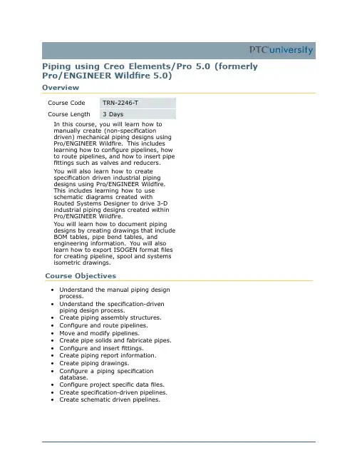
Piping using Creo Elements/Pro5.0(formerly Pro/ENGINEER Wildfire5.0)OverviewCourse Code TRN-2246-TCourse Length3DaysIn this course,you will learn how tomanually create(non-specificationdriven)mechanical piping designs usingPro/ENGINEER Wildfire.This includeslearning how to configure pipelines,howto route pipelines,and how to insert pipefittings such as valves and reducers.You will also learn how to createspecification driven industrial pipingdesigns using Pro/ENGINEER Wildfire.This includes learning how to useschematic diagrams created withRouted Systems Designer to drive3-Dindustrial piping designs created withinPro/ENGINEER Wildfire.You will learn how to document pipingdesigns by creating drawings that includeBOM tables,pipe bend tables,andengineering information.You will alsolearn how to export ISOGEN format filesfor creating pipeline,spool and systemsisometric drawings.Course Objectives•Understand the manual piping designprocess.•Understand the specification-drivenpiping design process.•Create piping assembly structures.•Configure and route pipelines.•Move and modify pipelines.•Create pipe solids and fabricate pipes.•Configure and insert fittings.•Create piping report information.•Create piping drawings.•Configure a piping specificationdatabase.•Configure project specific data files.•Create specification-driven pipelines.•Create schematic driven pipelines.Prerequisites•Introduction to Pro/ENGINEER Wildfire5.0Audience•This course is intended for engineers,involved in the3-D routing of mechanical piping systems and industrial piping systems.AgendaDay1Module1Introduction to PipingModule2Creating Piping Assembly StructuresModule3Configuring and Routing PipelinesModule4Moving and Modifying PipelinesModule5Configuring and Inserting FittingsDay2Module6Creating Solid Pipeline ModelsModule7Gathering Piping InformationModule8Creating Piping DrawingsModule9Specification Database OverviewModule10Setting Up Specification Databases:PipingModule11Setting Up Specification Databases:FittingsDay3Module12General Master Catalog FilesModule13Configuring Project Specific Data FilesModule14Specification-Driven Routing and Inserting Fittings Module15Using RSD Process and Instrumentation Diagrams Data Module16Schematic Driven Pipeline ModelingModule17Using ISOGEN PCF Data。

设计计算说明书课程名称:工业通风设计题目:某地下车库通风设计目录摘要 (3)第一章.设计概况 (4)1.1建筑概况 (7)1.2系统方案的划分确定 (8)1.3 规要求 (8)第二章.排风量与排烟量的计算 (10)2.1排风量的确定 (10)2.2排烟量的确定 (13)2.3送风量的确定 (13)2.4气流组织的分布 (13)2.5机械排烟系统的补风量的计算 (13)第三章.风管与风口的选择 (14)3.1风管材料的选择 (14)3.2风口尺寸及数量的计算送风量与排风量计算 (14)第四章.送风排演的水利计算 (15)4.1排烟排风管道的计算依据 (15)4.2送风管道的计算依据 (16)4.3车库的热负荷设计 (17)4.4防排烟系统设备选型及防火阀的设置 (18)4.5风机的选型 (19)4.6空调处理机组的选型 (26)4.7静压箱的选择 (28)结论 (30)致 (30)摘要本次课程设计是市某地下停车库的通风设计。
位于北纬113°17′;东经40°06′;海拔:1000m。
如何解决好地下车库的通风和防排烟问题是地下停车库设计中的一个重要问题。
要求设计既满足平时通风要求,排除汽车尾气和汽油蒸汽,送入新鲜空气;又要满足火灾时的排烟要求。
在本设计中,充分考虑排风,排烟,保暖等条件。
在保证满足设计要求的前提下,尽量使系统安装简单,造价低廉,性能可靠,维护方便。
关键字:,通风地下停车库4.4防排烟系统设备选型及防火阀的设置排烟风口的布置要符合有关的防火规的要求。
火灾发生时,严格按照消防控制程序,控制复合系统的排风功能与排烟功能的转换;控制防火阀、排烟阀、排烟防火伐等附件的开启与关闭;任何一个排烟阀或排烟防火阀的动作,可自动使风机高速运转或者使其余排烟风机启动。
考虑到风机的耐热程度与防止高于280°的帶火焰的煙氣蔓延,在風機入口附件設置280°关闭的排烟防火阀送风口(排烟口)送风口种类很多,但其功能基本相同。
目录1 设计说明 (1)1.1 概述 (1)1.1.1 设计依据 (1)1.1.2工程规模及主要工程量 (1)1.1.3工程投资及技术经济指标 (2)1.1.4 工程设计范围和内容 (2)1.2 设计建设方案 (2)1.2.1通信管道路由设计和位置确定原则 (2)1.2.2管道建设位置 (5)1.3 管道设计标准和规范要求 (5)1.3.1管道管材与管道建筑建材 (5)1.3.2塑料管材 (6)1.3.3通信管道埋设深度 (6)1.3.4通信管道铺设 (7)1.4 管道施工及施工验收规范技术要求 (7)1.4.1 工程测量 (7)1.4.2 土方工程 (8)1.4.3模板、钢筋及混凝土、砂浆 (11)1.4.4人(手)孔、通道建筑 (13)1.4.5塑料管道铺设 (16)1.4.6 口圈的安装 (17)1.4.7管道器材要求 (18)1.4.8工程验收 (23)1.4.9 验收项目和内容 (23)1.5 需要说明的其他问题 (26)2 预算 (27)2.1.2预算结果及技术经济分析 (27)2.1.3工程类别 (27)2.1.4预算编制依据 (28)2.1.6 有关费率、费用及单价的取定 (28)2.1.5 编制办法 (28)2.2 预算表格编号 (28)2.3 预算表格3附件附件:无为草市街等通信管道单项工程工程量汇总表(共1页)4图纸(1)无为城区管道路由图080700003Y(09)-YX-01⑵早市街(北大街-东大街)路段管道施工图080700003Y(09)-YX-02⑶儒江菜市场引入段管道施工图080700003Y(09)-YX-03⑷金鹏小区引入段管道施工图080700003Y(09)-YX-04商业大厦引入段管道施工图080700003Y(09)-YX-05⑹法院引入段管道施工图080700003Y(09)-YX-06⑺传感器厂引入段管道施工图080700003Y(09)-YX-07(8)北城小学引入段管道施工图080700003Y(09)-YX-08(9)房产局引入段管道施工图080700003Y(09)-YX-09(10)广电中心引入段管道施工图080700003Y(09)-YX-10(11)新世纪引入段管道施工图080700003Y(09)-YX-11(12)试验中学引入段管道施工图080700003Y(09)-YX-12(13)人民医院引入段直埋施工图080700003Y(09)-YX-13(14)小号手孔标准图TY-Y-YX-01 1 设计说明1.1 概述本工程为巢湖移动2008年基站接入网光缆线路工程之一:无为草市街等通信管道单项工程一阶段设计。
地下管线工程设计总说明一、 设计依据2、《威宁县控制性详细规划(2012~2030)》;3、《室外排水设计规范》 (GB50014—2006);4、《给水排水工程结构设计规范》(GB50069—2002);5、《城市工程管线综合规划规范》 (GB50289—98);6、《城市排水工程规划规范》 (GB50318—2000);7、《埋地塑料排水管道施工》 (04S520);8、《给水排水标准图集》——中国建筑标准设计研究院; 9、市政工程施工图集第3册——中国建筑工业出版社; 10、《给水排水设计手册》第5册——城镇排水(第2版); 11、1:1000的地形图; 12、工程地质勘探报告 二、 设计参数1、 雨水管的设计参数: 雨水流量公式: Q=φqF (升/秒) 雨水暴雨强度公式:)/(28.26691.2637.7165)/()17()lg 875.01(505595.0ha s L ha s L t P q ∙==∙++=其中:暴雨重现期P=3a ; t=t 1+t 2; t=8—15min;(t 取15min) 综合径流系数φ=0.602、 污水管道设计参数:根据规划的要求,本道路不同路段接受污水的范围不同。
居民生活用水定额为250L/(cap ·d )。
沿线埋没污水管对污水进行收集,出水口设置在道路低洼处,排水均排入低洼地带,后期在低洼处设置污水泵将污水抽至指定处理厂。
本道路检查井位置见管线平面布置图。
本道路污水管道为机场大道的排污主水管道,除本道路的污水外,后期在道路外的开发建城后的污水亦将通过此污水管进行排放,结合规划情况,为本道路的污水管道设计管径采用适当加大。
三、 排水管渠设计1. 设计原则:根据《威宁县控制性详细规划(2012~2030)》,本工程排水体制为雨、污分流制。
2. 雨水管渠分区及流向:本项目雨水管道在遇涵洞与桥梁处排入天然沟渠,在路线低洼处侧向排出路外,引入河沟,进入天然水体或低洼地带。

大气污染控制课程设计设计计算说明书环境科学与工程学院2019年10月目录1.任务说明 (1)1.1 项目名称 (1)1.2 设计要求 (1)1.3 设计依据 (1)1.4 设计主要参考资料 (1)2.原始资料 (2)2.1 建筑与结构 (2)2.2 地理、气象资料 (2)2.3 地形情况 (2)2.4 环境情况 (2)2.5 工艺资料 (2)3.设计内容与计算 (3)3.1 颗粒物控制流程方案 (3)3.2 颗粒物控制设备选型及计算 (3)3.2.1 颗粒物控制设备选型 (4)3.2.2 效率复核及设备出口负荷浓度计算 (6)3.3 管道布置、阻力计算及风机选型 (7)3.3.1 风机预选 (7)3.3.2 控制系统的管道布置 (8)3.3.3 系统管道阻力的计算 (8)3.3.4 计算示例 (11)3.3.5 风机复核 (11)3.4 烟囱高度计算及颗粒物最大落地浓度校核 (12)3.4.1 烟囱高度与内径设计 (12)3.4.2 烟气抬升高度计算 (13)3.4.3 颗粒物最大落地浓度校核 (14)附表 (17)1.任务说明1.1 项目名称上海某厂锅炉房颗粒物控制系统设计。
1.2 设计要求根据所给的资料,完成该锅炉房颗粒物控制系统的设计,要求确定含尘气体处理的流程,净化设备的型号、规格和主要尺寸,确定控制系统的布局,最后绘制控制系统平面布置图,必要的剖面图和系统图(轴测图),达到初步设计的深度,并简要的写出一份设计计算说明书。
1.3 设计依据(GB 3095-1996)《环境空气质量标准》:大气环境中总悬浮颗粒物浓度二级标准的日均浓度限值为0.3mg/Nm3;(GB 13271- 2001)《锅炉大气污染物排放标准》:二类地区安装的锅炉其最高允许烟尘排放浓度为80mg/Nm3。
1.4 设计主要参考资料1.工业锅炉除尘设备中国环境科学出版社19922.锅炉房实用设计手册第2版机械工业出版社20013.空气污染控制工程季学李、羌宁化学工业出版社20054.工业锅炉房实用设计手册机械工业出版社19915.工业锅炉房常用设备手册机械工业出版社19936.全国通用通风管计算表中国建筑工业出版社19777.全国通用通风管的配件表中国建筑工业出版社19792.原始资料2.1 建筑与结构该锅炉房为独立式单层建筑,建于2013年8月,总面积为292平方米,其中包括锅炉房、风机及除尘器室、水泵室和值班室,各室在建筑总体上的布置见电子版蓝图文件。

给水排水管网课程设计指导书福建工程学院生态环境与城市建设学院给水排水教研室2015年12月给水管网课程设计指导书班级学生姓名学号一、设计步骤:1、用水量计算(1)、确定用水量标准,计算城市最高日用水量。
居民最高日生活用水量按城市分区用水量标准计算.工厂最高日生产用水量,按工厂性质、产品数量等分别计算,工厂用水量还包括工人在工作时生活用水量及班后淋浴用水量。
此外,还有浇洒道路、绿地用水量。
加上未预见水量和管网漏失水量,即得该城市最高日设计用水量。
(2)、计算城市最高日最高时用水量。
(3)、计算消防时用水量。
2、供水系统方案选择(1)选定水源及位置和净水厂位置;(2)选定供水系统方案.3、管网定线根据选定的给水系统方案,进行配水管网定线。
管网布置采用环状管网和树状管网相结合的方式.4、清水池容积,水塔(或高地水池)容积计算。
5、管段设计流量计算(1)比流量计算采用长度比流量的方法进行计算。
分区用水量标准若不相同应分别计算比流量。
(2)节点流量计算先由比流量计算出沿线流量,再用沿线流量算出节点流量。
(3)进行流量分配①枝状网水流方向唯一,流量分配唯一,任一管段的流量等于以后所有节点流量总和。
②环状网流量分配有多种组合方案.基本原则:满足供水可靠性前提下,兼顾经济性。
注:此分配值是预分配,用来选择管径,真正值由平差结果定。
6、管网水力计算和平差计算:给水管网各管段直径应按最高日最高时用水量和经济流速来确定,按管段预分配流量和所选定的管径,查水力计算表,即可求得各管段的1000i,按h=iL计算各管段水头损失.管网平差采用哈代克罗斯法,通过平差计算确定管网的实际流量分配,并计算相应的水头损失。
平差计算采用列表形式,并以平差计算简图的形式标识平差计算过程中的流量分配变化和校正流量大小方向。
对供水方案的除了进行最大用水时管网平差之外,还需要进行消防校核平差及事故校核。
7、水泵扬程和水塔高度计算。
由管网的控制点开始,按相应的计算条件(最高时、消防时、事故时等),经管网推算到二级泵站,求出水泵的总扬程及供水总流量.8、节点水压标高计算。
目录页数1. 目的 (1)2. 适用围 (1)3. 参考文件 (1)4. 定义 (1)5. 各阶段管道布置图的容和职责 (2)5.1 主要管道走向布置图(MAJOR PIPING ROUTING LAYOUT) (2)5.1.1主要管道走向布置图设计依据 (2)5.1.2基础设计阶段(含初步设计)主要管道走向布置图的容和深度 (2)5.1.3基础设计阶段(含初步设计)主要管道走向布置图的适用围 (2)5.2详细管道研究图(DETAILED PIPING STUDIES) (3)5.2.1设计依据 (3)5.2.2详细管道研究图的容和深度 (3)5.2.3详细管道研究图的适用围 (3)5.3详细管道布置图(DETAILED PIPING LAYOUT) (4)5.3.1设计依据 (4)5.3.2详细设计阶段管道布置图的容和深度 (4)5.3.3详细设计阶段管道布置图的适用围 (5)6. 管道布置图的绘制 (5)6.1 绘制管道布置图的通用要求 (5)6.1.1图纸尺寸、发行栏和标题栏 (5)6.1.2比例和尺寸单位 (8)6.1.3线型,文字及数字 (8)6.1.4图面的布置 (11)6.1.5 北向标及管口表 (12)6.2 制图规定 (17)6.2.1平面图的划分 (18)6.2.2管道图中例外表示的符号 (18)6.2.3管道布置图上设备应表示的容 (19)6.2.4管道布置图上建(构)筑物应表示的容 (23)6.2.5定位轴线 (24)6.2.6管道布置图上仪表、电气应表示的容 (25)6.2.7管道布置图上管道应表示的容 (25)6.2.8管道布置图上尺寸标注 (34)6.2.9管道布置图的立面图和详图 (44)6.2.10 管架标记 (53)7. 管道布置图的质量保证 (53)8. 管道布置图的修改、签署、加盖印章 (54)8.1 管道布置图的修改 (54)8.2 管道布置图的签署 (54)8.3 管道布置图加盖压力管道设计资格印章 (54)9 附录:图例符号 (55)1. 目的编制本手册的目的是为了规寰球公司管道专业管道布置图设计的容、表示方法和形式。


雨水课程设计一、划分排水流域及管道定线根据该市区的总平面布置图,可知该市地形西面较为平坦、东面较为陡峭,分为河南河北两区,雨水就近排入各雨水口。
该市内建筑较多,相应的交通量会比较大,故雨水管道采取暗管。
根据总平面图给出的标高绘制等高线。
再根据等高线合理布置雨水口,适当划分排水区域。
根据地形、雨水口分布定管线,使绝大部分雨水以最短的距离排入街道低侧的雨水管道。
拟将该市划分为82个流域。
二、划分设计管段根据管道的具体位置,在管道转弯处、管径或坡度改变出,有支管接入出或两条以上管道交汇处以及超过一定距离的直线管端上都应该设置检查井。
把两个检查井之间流量没有变化且预计管径和坡度也没有变化的管段定位设计管段。
并从管段从下游往下游按循序进行检查井的编号。
三、划分并计算各设计管段的汇水面积各设计管段汇水面积的划分应结合地形坡度、汇水面积的大小以及雨水管道布置等情况而划定。
地形较平坦时,可按就近排入附近雨水管道的原则划分汇水面积;地形坡度较大时,应按地面雨水径流的水流方向划分汇水面积。
并将每块面积进行编号,计算其面积的数值。
下表为汇水面积计算表。
汇水面积计算表四、确定平均径流系数屋面,径流系数0.90,所占比例43%;砼沥青路面,径流系数0.90,所占比例8%;碎石路面,径流系数0.40,所占比例4%;非铺砌地面,径流系数0.30,所占比例19%;沥青表面处理的碎石路面,径流系数0.60,所占比例6%;公园和菜地,径流系数0.15,所占比例20%。
故平均径流系数为:0.600.1520%0.606%0.3019%0.404%0.908%0.9043%=⨯+⨯+⨯+⨯+⨯+⨯=P ψ五、根据确定的设计参数,求单位面积径流量q 0设计径流量公式:nb t cLgP qF Q )()1(167A 1++==ψ有关参数:A1=20 C=0.7 b=19 n=0.86故单位面积径流量为:(取重现期P=1a)5.020)92(2004t q ∑+=六、确定起点埋深根据冰冻情况,雨水管道衔接要求及承受荷载的要求,确定管道起点的埋深。
城市给水管道工程设计——某县城给水管网初步设计课程名称:专业名称:班级:学号:姓名:指导老师:能否组长:给水管网计算说明书1 给水管网设计任务书设计目的和要求课程设计的目的,在于培育学生运用所学的理论知识,解决实质问题,进一步提升计算、制图和使用规范与技术资料的能力。
设计要注意贯彻国家相关的基本建设目标政策,做到技术上可能,经济上合理。
为了达到这一目的,学生应当深入复习相关课程,充足理解它的原理,在此基础上,学会独立查阅技术文件,确立合理的技术方案,逐渐建立正确的设计看法。
经过技术能基本掌握给水管网的设计程序和方法,较娴熟地进行管网平差,增强基本技术和运作技巧的训练。
设计题目某县城给水管网初步设计设计原始资料概括某县城位于我国的广东省,依据城市建设规划,市内建有居民区、公共建筑和工厂。
详见规划地形图。
城市用水状况城市用水按近期人口 412000 万人口设计,远期( 10 年)人口增添 10%,市里以 5 层的多层建筑为主。
表 1 生活用水变化规律表公司用水变化 居民用水变化百公司用水变化 居民用水变化百时间 分数%时间 分数%百分数%百分数%0-1 12-13 1-2 13-14 2-3 14-15 3-4 15-16 4-5 16-17 5-6 17-18 6-7 18-19 7-8 19-20 8-9 20-21 9-10 21-22 10-11 22-23 11-1223-24表 2 公共建筑用水量表用水单位用水人数用水标准用水时间及水量分派医院800 床24h影剧院600 人/ 场 3 场/日24h中学2000 人按规范的最高标准查取6-22 点旅馆600 床均匀24h 火车站流感人口 5000 人6-22 点师专3000 人6-22 点少儿园2000 人6-22 点表 3 公司生产用水表工厂名称生产用水人员用水用水时间备注(万 m3/d )人数(人)用水标准( h)酒厂1000 24 高温人数50%食品厂800 24 高温人数30%工艺品厂500 按规范标准查取6-22 点高温人数70%肉联厂500 3-19 点高温人数0%机械厂1000 6-22 点高温人数20%注: 1)下班后淋浴人数100%; 2)公司生产用水变化规律:两班制的按16 小时均匀供水,三班制的变化系数见表 ;3 )工厂的生活用水和淋浴用水变化规律赐教材16 页表2-1;4) 建筑物的耐火等级 3 级,生产类型为丙类,建筑物最大概积34000m;5)居民生活用水变化规律见表1。
本科《给排水管道工程》课程设计说明书污水管道系统设计学院环境科学与工程学院专业环境工程班级2004级环境工程1班学生姓名李达宁学号200433138282电子邮件daning13@126.c0m联系电话39384692指导教师陆少鸣污水管道系统设计说明书1.基本资料从小区平面图可知该区域地势自西北方向向东南方向倾斜,坡度较小,无明显分水线,可划分为一个排水流域。
本设计采用分流制排水系统,只考虑容纳生活污水、工业废水、工业生活污水。
根据比较,设计采用平行式管道布设形式,可相对截流式布设形式节省管材和土方量。
3条街道支管埋于街区地势较低的一侧,统一汇入主干管中。
主干管在小区最东侧自北向南布设,将污水排入污水处理厂后处理2.街区编号并计算其面积将各街区编号,并用箭头标出各街区污水排出的方向(如图1所示)。
计算各街区面积列由街坊总面积84.6×2410m ,居住人口密度为400人/2410m ,则服务总人口数为84.6×400=33840人,居民污水量标准为140L/人.d ,则计算居民平均日生活污水量为: Q d =3600243384014036002411⨯⨯=⨯∑i i N q =54.84(L/s )计算总变化系数为: Kz =11.011.084.547.27.2=d Q =1.74 计算居民生活污水设计流量:Q1=360024111⨯∑iizNqK=K z1Q d=1.74×54.84=95.42(L/s)工厂的生活污水和淋浴污水设计流量已直接给出,为:Q2+Q3=8.24+6.84=15.08(L/s)生产污水设计流量为Q4=26.4L/s将各项污水设计流量直接求和,得该街坊污水设计总流量:Q h=Q1+Q2+Q3+Q4=95.42+15.08+26.4=136.9(L/s)3.划分管段,计算流量该街坊平面如图所示图中用箭头标出了各街坊污水排出的方向,经计算各街坊的汇水面积列于表1中。
说明书管道设计总体部分项目文件号专业文件号LPEC 562071D2202 顾客要求40-00/S2设计阶段 详细设计 第 1 页 共 31 页工厂(公司)名称:中国化工 正和集团股份有限公司项目名称:DCC 装置装置及(或)单元名称:DCC签名 编 制: 校 对: 审 核: 项目审核:日期6 5 4 3 2 1 修改说明本文件内容未经 LPEC 书面同意不允许扩散至第三方编制校对 审核 日期格式编号:LF-Ch-00G-02-2004说明书项目文件号专业文件号LPEC 562071D2202 顾客要求40-00/S2详细设计第 2 页 共 31 页目次1 概述……………………….…………………………………..……………….……….3 2 装置布置设计………………………………………………………………………………4 3 管道布置设计……………………………………………………………………………... 6 4 管道器材选用……………………………….………………………………………..…...13 5 管道机械设计……………………………….………………………………………..…...16 6 施工要求…………………..………..…………………………………….……………17 7 管道布置图识图方法…………..………..…………………………………….…………21 8 管道主要工程量…………..………..…………………………………….……………28 9 附件…………..………..……..…………………………………….……………29 10 附录一…………..………..……..…………………………………….……………30本文件内容未经 LPEC 书面同意不允许扩散至第三方格式编号:LF-Ch-00G-02-2004说明书项目文件号专业文件号LPEC 562071D2202 顾客要求40-00/S2详细设计第 3 页 共 31 页1 概述1.1 装置组成中国化工 正和集团股份有限公司 DCC 装置为一个联合装置,包括 DCC(562071D2202)、产品精制 (562071D2234)、气体分馏 (562071D2219)、溶剂再生(562071D2261) 及污水提升(562071D2511)五个部分。