遥感卫星传感器及其成像方式
- 格式:ppt
- 大小:1.91 MB
- 文档页数:15


使用卫星遥感技术进行测绘的原理和操作指南导语:卫星遥感技术是一种通过卫星获取地球表面信息的技术手段,它可以帮助我们进行测绘工作。
本文将介绍卫星遥感技术的原理以及使用该技术进行测绘的操作指南。
一、卫星遥感技术的原理卫星遥感技术是利用人造卫星拍摄地球表面的影像,然后通过处理和分析这些影像来获取地理信息。
其原理主要包括传感器、数据传输和数据处理三方面。
1. 传感器:卫星上搭载了多种传感器,如光学传感器、红外传感器和微波传感器等。
光学传感器可以通过记录反射、散射和辐射的能量来获取地表特征,红外传感器可以检测热量的分布,而微波传感器则可以穿透云层和雾霾获取地表信息。
2. 数据传输:卫星通过无线电波将采集的图像和数据传输回地面接收站。
这些图像和数据通过卫星发射器发射到地面,并通过地面接收站接收和记录。
这样的数据传输过程保证了数据的实时性和准确性。
3. 数据处理:卫星获取的原始图像和数据需要经过处理和分析才能被有效利用。
常见的数据处理方法有图像纠正、图像增强、图像分类和信息提取等。
图像纠正能够消除传感器本身和地球自转对图像的影响,图像增强则能够提高图像的质量和细节,图像分类和信息提取能够从图像中提取出我们所关注的地理信息。
二、使用卫星遥感技术进行测绘的操作指南使用卫星遥感技术进行测绘需要以下步骤:1. 数据获取:首先需要获取卫星遥感数据。
可以通过购买商业卫星图像,或者使用公开的遥感数据源,如美国地质调查局(USGS)提供的Landsat数据。
从官方渠道获取数据可以保证其质量和可信度。
2. 数据处理:将获取的卫星遥感数据进行处理,包括图像纠正、图像增强和图像分类等步骤。
图像纠正能够消除由于传感器本身和地球自转引起的变形和畸变。
图像增强可以提高图像的质量和细节,并使地表特征更加清晰可见。
图像分类则是将图像根据不同的特征和像素值进行分类,从而提取出我们所关注的地理信息。
3. 地理信息提取:利用处理后的卫星遥感数据,可以提取出所需的地理信息。

遥感卫星知识解读随着科技的不断发展,遥感卫星技术已经成为了现代地球科学研究的重要手段之一。
遥感卫星可以通过对地球表面的观测,获取大量的地理信息数据,为人类认识和探索地球提供了重要的支持。
本文将从遥感卫星的基本原理、应用领域和未来发展等方面进行解读。
一、遥感卫星的基本原理遥感卫星是一种通过对地球表面进行遥感观测,获取地理信息数据的卫星。
其基本原理是利用卫星上的传感器对地球表面进行观测,通过对反射、辐射、散射等现象的分析,获取地球表面的信息。
遥感卫星的传感器可以分为光学传感器和微波传感器两种类型。
光学传感器主要利用可见光、红外线等波段的电磁波进行观测,可以获取地球表面的颜色、形状、温度等信息。
微波传感器则主要利用微波波段的电磁波进行观测,可以获取地球表面的高度、湿度、温度等信息。
遥感卫星的传感器可以根据不同的应用需求进行选择和组合,以获取更加全面和准确的地理信息数据。
二、遥感卫星的应用领域遥感卫星技术在地球科学研究、资源调查、环境监测、军事侦察等领域都有广泛的应用。
以下是几个典型的应用领域:1. 地球科学研究:遥感卫星可以对地球表面的地貌、地质、水文、气象等进行观测,为地球科学研究提供了重要的数据支持。
例如,利用遥感卫星可以对地球表面的地震、火山、洪涝等自然灾害进行监测和预警。
2. 资源调查:遥感卫星可以对地球表面的土地、水资源、矿产资源等进行调查和评估,为资源开发和利用提供了重要的数据支持。
例如,利用遥感卫星可以对农田、森林、草原等进行监测和评估,为农业生产和生态保护提供了重要的数据支持。
3. 环境监测:遥感卫星可以对大气、水体、土地等环境要素进行监测和评估,为环境保护和治理提供了重要的数据支持。
例如,利用遥感卫星可以对大气污染、水体污染、土地退化等进行监测和评估,为环境保护和治理提供了重要的数据支持。
4. 军事侦察:遥感卫星可以对敌方军事目标进行监测和侦察,为军事作战提供了重要的情报支持。
例如,利用遥感卫星可以对敌方军事设施、兵力部署等进行监测和侦察,为军事作战提供了重要的情报支持。

卫星遥感技术原理
卫星遥感技术是利用卫星对地面目标进行观测和测量的一种技术。
其原理主要依靠传感器和信号处理系统。
首先,卫星上搭载了各种传感器,如光学传感器、热红外传感器、微波雷达等。
这些传感器能够感测不同波段的电磁辐射,包括可见光、红外线和微波等。
当卫星经过地面目标时,传感器会接收地面目标发出的或反射的电磁辐射。
光学传感器通过接收可见光和红外线辐射来获取地表的光谱、形态和温度信息。
热红外传感器则可以测量地表的热辐射,用于研究地表温度分布、火灾监测等。
微波雷达则利用微波辐射来观测地表形貌、湿度、植被覆盖等。
接收到的电磁辐射信号会被卫星上的信号处理系统进行处理和解析。
首先,传感器采集到的原始数据会经过去噪、辐射校准等预处理步骤,以消除干扰和提高数据质量。
然后,数据会进行数字化和压缩,并存储在卫星的存储介质中。
卫星会通过与地面接收站进行通信,将数据传回地面。
在地面接收站,接收到的数据会通过解压缩和分析处理,得到各种产品和图像。
科学家、工程师和决策者可以利用这些数据进行地质勘探、环境监测、农业管理等各种应用。
同时,这些数据还可以与历史数据进行比较和分析,以研究地球变化和预测未来趋势。
总的来说,卫星遥感技术通过卫星上的传感器对地面目标的电
磁辐射进行感测和测量,并通过信号处理系统将数据传回地面。
这种技术在资源管理、环境保护和灾害监测等方面具有广泛的应用前景。

遥感应用原理与方法遥感(Remote Sensing)是指利用航空器、卫星、遥感卫星等遥感平台所获取的地球表面和大气层信息,通过传感器对辐射能的检测和记录进行处理分析,从而得到具有一定目的和目标的地表、大气和天体等信息的科学技术。
遥感应用原理与方法涵盖遥感数据获取、处理与分析的步骤,以下将分别介绍。
一、遥感数据获取遥感数据获取是指利用航空器、卫星或其他遥感平台采集遥感数据的过程。
其主要原理是利用传感器对地球表面进行辐射能的接收,然后将接收到的辐射能转化为数字信号或图像数据。
常见的遥感数据获取方式包括航空摄影、卫星遥感和无人机遥感等。
1.航空摄影:通过航空摄影机将地面目标的影像记录在感光介质上,再经过处理和解译,获取地表信息。
航空摄影可以获得高分辨率的影像数据,但覆盖范围相对较小。
2.卫星遥感:利用具有遥感功能的卫星进行影像获取。
由于卫星高空运行,可以覆盖更大的地表面积,并且可以获取大范围的连续遥感数据,有利于对地球表面进行长时间和全面的监测。
3.无人机遥感:无人机遥感是近年来发展起来的新兴技术。
无人机具有灵活性高、成本低等特点,在小范围内能够获得高分辨率的影像数据,适用于小区域目标的监测和分析。
二、遥感数据处理与分析遥感数据处理与分析是指将采集到的遥感数据进行预处理和信息提取,得出目标地区的特征和信息。
遥感数据处理与分析主要包括遥感图像预处理、信息提取与分类、变化检测和遥感时空分析等。
1.遥感图像预处理:遥感图像预处理主要通过空间校正、辐射校正和大气校正等处理,使图像质量更好、减少噪声,以便进行后续分析。
2.信息提取与分类:信息提取与分类是指通过特定的算法和模型,将遥感图像中的目标进行自动或半自动的提取和分类。
常见的方法包括目标识别与定位、纹理分析、光谱解混和等。
3.变化检测与监测:变化检测是指通过对多个时间段的遥感图像进行比较,找出地表变化的区域和特征。
例如用于城市扩张、植被遥感、地质灾害监测等。
卫星成像的原理和应用1. 卫星成像的原理卫星成像是利用人造卫星搭载的相机设备来获取地球表面的图像信息的技术。
卫星成像的原理主要包括以下几个方面:1.1 光学原理卫星成像利用光学器件来接收地球表面反射的光线,并将其转化为电信号。
光学器件包括透镜、光栅、滤光片等,它们的作用是对光信号进行聚焦、分光和滤波,以提高图像的清晰度和色彩还原度。
1.2 探测原理卫星成像的相机设备是由光电探测器和信号处理器组成的。
光电探测器主要有CCD(电荷耦合器件)和CMOS(互补金属氧化物半导体)传感器两种类型,它们能将光信号转化为电信号。
信号处理器则对电信号进行放大、滤波、模数转换等处理,以获得高质量的图像数据。
1.3 遥感原理卫星成像利用遥感技术获取地球表面的图像信息。
遥感是指通过遥距探测和测量地面目标物理特性的技术。
卫星利用传感器获取地球表面的光谱、辐射、形态等信息,然后通过数据处理和解译,得到地表的图像和相关地理信息。
2. 卫星成像的应用卫星成像技术在多个领域有着广泛的应用,以下列举了几个重要的应用领域:2.1 地球观测和环境监测卫星成像技术可以提供全球范围内的地表观测和环境监测数据。
通过获取地表的图像和辐射信息,可以监测全球气候变化、森林覆盖变化、冰川消融等环境变化情况,为环境保护和自然资源管理提供科学依据。
2.2 农业和农村发展卫星成像技术对农业和农村发展具有重要意义。
通过获取农田的图像和植被指数等信息,可以实现农作物的遥感监测、病虫害预警和农田水资源管理等功能,提高农业生产效益和农村发展水平。
2.3 自然灾害监测与应急响应卫星成像技术在自然灾害监测和应急响应中有着重要作用。
通过监测自然灾害的影响范围和程度,可以及时采取应急措施,减少损失并提供救援指导。
例如,在地震、洪水、火灾等自然灾害发生时,通过卫星成像获取受灾地区的图像,可以快速评估灾害影响,指导救援工作。
2.4 城市规划和土地利用卫星成像技术在城市规划和土地利用方面具有重要应用价值。
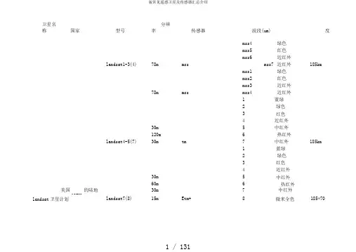
卫星名称国家型号分辨率传感器波段(um)宽度mss4绿色mss5红色mss6近红外landsat1-3(4)78m mss mss7近红外185kmmss1绿色mss2红色mss3近红外78m mss mss4近红外1蓝绿2绿色3红色4近红外30m5中红外120m6热红外landsat4-5(7)30m tm7中红外185km1蓝绿2绿色3红色4近红外30m5中红外60m6热红外美国的陆地30m7中红外NASAlandsat卫星计划landsat7(8)15m Etm+8微米全色185*7010m CCDS(SPOT1)P全色B1绿色第一代:CCD B20.红色(4)20m B3近红外60km10M M全色B1绿色B2红色第二代spot4B3近红外(5)20M HRVIR(?)B4短波红外60kmB1绿色B2红色10M HRG B3近红外法国空间研究中心第二代spot520M B4短波红外spot(CNES)(5)HRS P:全色60km全色(?)蓝多光谱绿(条红美国DigitalGlobe带quickbird企业quickbird(4)推扫式扫描成像方式近红外16.5*165)美国洛克希德马1m全色丁企业(卫星)雷(星下蓝ikonos神企业(传输数ikonos(5)点)4m绿据办理系统)柯达红企业(光学系统)近红外orbview-1(1)10km日照成像仪1个光谱1300km宽视场大海遥感器orbview-2(8)seawifs(?)2800km orbview美国GeoEye企业orbview-3(5)1m全色8km4m1m全色4m超光谱成像谱段orbview-48m高分辨率相机200条8km蓝绿红德国全部的商用卫红边rapideye星Rapideye-5(5)5m近红外77km二十一世纪空间技32m 绿术应用股份有限公北京一号小卫星红北京一号司(中国)(4)4m32米多光谱传感器近红外600kmCBERS-1CBERS-2(11)258m波段6,7,8:78m波段9:156m中巴资源中巴资源卫星(中卫星国与巴西)CBERS-2b(8)20m 4米全色传感器24km CCD相机1:~微米推扫式2:~微米3:~微米4:~微米5:~微米113km10:~微米宽视场成像仪(WFI)推扫11:~微米式(分立相机)890km 红外多光谱扫描仪6:~微米(可见/(IRMSS)近红外波段)震荡扫描式(前向和反向)7:~微米8:~微米(短波红外波段)9:~微米(热红外波段)CCD相机B1113kmB2B3B4B5高分辨率相机(HR)B627km宽视场成像仪B7258m(WFI)B8890km全色5m B1:B2:B3:多光谱10m P/MS相机60km资源一号02C卫单台星(简称ZY-127km;两台02C)HR相机(?)54km前视相机52km后视相机52km正视相机51km资源卫星中国资源三号(4)6m多光谱相机51km 美国NOAA极轨NOAA是太阳同步HIRD/32248km 卫星(美国国家海极轨卫星,采纳双高分辨率红外辐射探测仪noaa洋和大气管理局星运转,同一地域45AMSU-A2226km(National每日可有四次过境Oceanic and时机。

遥感传感器综述一、遥感传感器的概念遥感传感器是测量和记录被探测物体的电磁波特性的工具,是遥感技术系统的重要组成部分。
遥感传感器根据不同工作的波段,适用的传感器是不一样的。
目前遥感中常用的传感器大致上可分为如下几类:1)摄影类型的传感器2)扫描类型的传感器3)雷达成像类型的传感器4)非图像类型的传感器摄影机主要用于可见光波段范围。
红外扫描器、多谱段扫描器除了可见光波段外,还可记录近紫外、红外波段的信息。
雷达则用于微波波段。
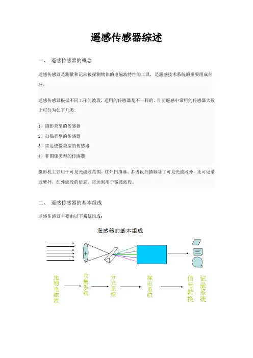
二、遥感传感器的基本组成遥感传感器主要由以下系统组成:无论哪一种传感器,它们基本是由收集系统、探测系统,信息转化系统和记录系统四部分组成。
(1)收集系统:遥感应用技术是建立在地物的电微波谱特性基础之上的,要收集地物的电磁波必须要有一种收集系统,该系统的功能在于把接收到的电磁波进行聚集,然后关往探测系统。
不同的遥感器使用的收集元件不同,最基本的收集元件是透镜、反射镜或天线。
对于多波段遥感,收信系统还包括按波段分波束的元件,一般采用各种散元个成分光之件,例如:滤光片、棱镜、光栅等。
(2)探测系统:遥感器中最重要的部分就是探测元件,它是真正接收地物电磁辐射的器件,常用的探测元件有感光胶片,光电敏感元件,固体敏感元件和波导等。
(3)信号转化系统:除了摄影照相机中的感胶片,电广从光辐射输入到光信号记录,无须信号转化之外,其它遥感器都有信号转化问题,光电敏感元件,固体敏感元件和波导等输出的都是电信号,从电信号转换到光信号必须有一个信号转化系统,这个转换系统可以直接进行电光转化,也可进行间接转换,先记录在磁带上,再经磁带加放,仍需经电光转换,输出光信号(4)记录系统:遥感器的最终目的是要把接收到的各种电磁波信息,用适当的方式输出,输出必须有一定的记录系统,遥感影像可以直接记录在摄影胶片等上,也可记录在磁带上等。
三、遥感影像的分辨率1 空间分辨率2 波谱分辨率3 辐射分辨率(辐射灵敏度)1 空间分辨率:能把两个相邻目标作为两个清晰实体记录下来的两目标间的最小距离。
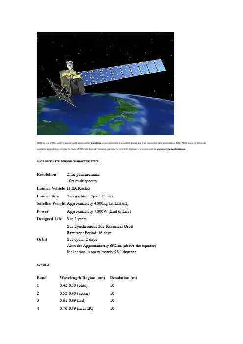
ALOS is one of the world's largest earth observation satellites whose function is to collect global and high resolution land observation data. ALOS data will be made available at conditions similar to those of ERS and Envisat missions, namely for scientific 'Category-1' use as well as commercial applications.ALOS SATELLITE SENSOR CHARACTERISTICSResolution 2.5m panchromatic10m multispectralLaunch Vehicle H-IIA RocketLaunch Site Tanegashima Space CenterSatellite Weight Approximately 4,000kg (at Lift-off)Power Approximately 7,000W (End of Life)Designed Life 3 to 5 yearsOrbit Sun Synchronous Sub-Recurrent OrbitRecurrent Period: 46 daysSub cycle: 2 daysAltitude: Approximately 692km (above the equator) Inclination: Approximately 98.2 degreesAVNIR-2Band Wavelength Region (µm)Resolution (m) 10.42-0.50 (blue)1020.52-0.60 (green)1030.61-0.69 (red)1040.76-0.89 (near-IR)10PALSARBand Frequency (GHz)Resolution (m)SAR-L 1.310 and 100PRISMBand Wavelength Region (µm)Resolution (m) PAN0.52-0.77 2.5ASTER Satellite System: Sensor CharacteristicsLaunch Date 18 December 1999 at Vandenberg Air Force Base, California, USAEquator Crossing10:30 AM (north to south)Orbit705 km altitude, sun synchronousOrbit Inclination98.3 degrees from the equatorOrbit Period98.88 minutesGrounding Track RepeatCycle16 daysResolution15 to 90 metersThe ASTER instrument consists of three separate instrument subsystems:VNIR (Visible Near Infrared), a backward looking telescope which is only used to acquire a stereo pair imageSWIR (ShortWave Infrared), a single fixed aspheric refracting telescopeTIR (Thermal Infrared)ASTER high-resolution sensor is capable of producing stereoscopic (three-dimensional) images and detailed terrain height models. Other key features of ASTER are: ∙Multispectral thermal infrared data of high spatial resolution∙Highest spatial resolution surface spectral reflectance, temperature, and emissivity data within the Terra instrument suite∙Capability to schedule on-demand data acquisition requestsASTER has 14 bands of information. For more information, please see the following table:Instrument VNIR SWIR TIRBands1-34-910-14Spatial Resolution15m30m90mSwath Width60km60km60kmCross Track Pointing± 318km (± 24 deg)± 116km (± 8.55 deg)± 116km (± 8.55 deg)Quantisation (bits)8812The CBERS satellite is composed of two modules. The payload module houses the optical system (CCD - High Resolution CCD Cameras, IRMSS - Infra-Red Multispectral Scanner e WFI - Wide Field Imager) and the electronic system used for Earth observation and data collecting with a resolution capability ranging from 20 meters to 260 meters. The service module incorporates the equipment that ensures the power supply, control, telecommunications and all other functions needed for the satellite operation.CBERS-2 SATELLITE SENSOR SPECIFICATIONSResolution20m - 260mLaunch Date October 21, 2001Launch Location Taiyuan Satellite Launch Center in China Total Mass1450kgPower Generation1100wSun-Synchronous Orbit 778km14 revolutions per dayEquator Crossing Time10:30 amLifetime Orbit 2 yearsCBERS-2 OPTICAL SPECIFICATIONSThe CBERS-2 satellite sensor was designed for global and scalable coverage that include cameras that make optical observations and to collect data on the environment. The unique characteristics of CBERS-2 are its multi-sensor payloads with different spatial and spectral resolution capabilities and frequencies from each camera allowing for various mapping applications.WFI - Wide Field Imager— Large Territories (890km wide) — 5 day intervalSpectral bands0,63 - 0,69 Μm (red) 0,77 - 0,89 Μm (infrared)Field of view60 °Spatial resolution260 x 260 mSwath width890 kmTemporal resolution 5 daysRF carrier frequency8203,35 MHzImage data bit rate1,1 Mbit/s EIRP 31,8 dBmCCD - High Resolution Camera— Detailed City and Region StudiesSpectral bands50,51 - 0,73 Μm (pan) 0,45 - 0,52 Μm (blue) 0,52 - 0,59 Μm (green) 0,63 - 0,69 Μm (red)0,77 - 0,89 Μm (near infrared) Field of view 8,3° Spatial resolution 20 x 20 m Swath width 113 kmMirror pointing capability±32° Temporal resolution 26 days nadir view (3 days revisit) RF carrier frequency 8103 MHz e 8321 MHz Image data bit rate2 x 53 Mbit/s EIRP 43 dBmIRMSS - Infrared Multispectral Scanner — Spectral coverage (120km wide) — 26 daysSpectral bands 40,50 - 0,80 Μm (panchromatic) Field of view2,1 °Spatial resolution 2,7 x 2,7 m Imaged strip width 27 km (nadir)Temporal resolution 130 days in the proposed operation Quantization8 bitsThe FORMOSAT-2's Image Processing System (IPS) is independently developed by NSPO. It is designed to process images by tasking the satellite according to the user's needs. Images are then taken and downloaded through X-band antenna, then crossed with through IPS such as radiometric and geometric corrections and stored in computers. These files will be delivered to the end users based on the clients' requests.FORMOSAT-2 SATELLITE SENSOR SPECIFICATIONSImaging Data • B&W: 2-mProducts• Color: 2-m (merge)• Multispectral (R, G, B, NIR): 8-m• Bundle (separate Pan and MS images)Spectral Bands• P: 0.45 - 0.90 µm (Panchromatic)• B1: 0.45 - 0.52 µm (Blue)• B2: 0.52 - 0.60 µm (Green)• B3: 0.63 - 0.69 µm (Red)• B4: 0.76 - 0.90 µm (Near-infrared)Sensor Footprint24 km x 24 kmRevisit Interval DailyViewing Angles Cross-track and along-track (forward/aft): +/- 45°Satellite Tasking Yes - Panchromatic and multispectral images can be acquired at thesame timeImage Dynamics8 bits/pixelImage File Size (level 1A without metadata)• MS: 35 Mb • Pan: 137 MbFORMOSAT-2 products are available in 3 preprocessing levels:∙Level 1ARadiometric corrections to remove distortions due to variations in sensitivity of elementary detectors in the imaging sensor.∙Level 2ARadiometric corrections identical to Level 1A. Geometric corrections to frame the image in a given map projection (default projection is UTM WGS 84).∙OrthoRadiometric corrections identical to Level 1A. Geometric corrections to frame the image in a map projection specified by the user and to remove relief distortions (map and/or control points and digital elevation model supplied by user).FORMATProducts are delivered in DIMAP format:∙Image in GeoTiff∙Metadata in XMLDELIVERY∙Posted online (FTP) within 48 - 72 working hours of acquisition∙CD-ROM/DVD if requestedFORMOSAT-2 Mapping ApplicationsFORMOSAT-2 satellite images support monitoring and detecting land change for any specific region for various industries and mapping applications. Users can task the satellite to keep track by scheduling revisits to detect changes on land and infrastructures, to observe movement overtime and helps to keep a current database to know what is happening on the ground so users can make informed decisions.GEOEYE-1: SATELLITE SENSOR CHARACTERISTICSThe following specifications are courtesy of GeoEye, and are subject to change.IMAGING & COLLECTION SPECIFICATIONSLaunch Date September 6, 200811:50:57 to 11:52:21 AM PSTCamera Modes• Simultaneous panchromatic and multispectral(pan-sharpened)• Panchromatic only• Multispectral onlyResolution0.41 m / 1.34 ft* panchromatic (nominal at Nadir)1.65 m / 5.41 ft* multispectral (nominal at Nadir)Metric Accuracy/Geolocation CE stereo: 2 m / 6.6 ftLE stereo: 3 m / 9.84 ftCE mono: 2.5 m / 8.20 ftThese are specified as 90% CE (circular error) for thehorizontal and 90% LE (linear error) for the vertical with noground control points (GCP's)Swath Widths & Representative Area Sizes• Nominal swath width - 15.2 km / 9.44 mi at Nadir• Single -point scene - 225 sq km (15x15 km) • Co ntiguous large area - 15,000 sq km (300x50 km) • Contiguous 1° cell size areas - 10,000 sq km (100x100 km)• Contiguous stereo area - 6,270 sq km (224x28 km) (Area assumes pan mode at highest line rate) Imaging AngleCapable of imaging in any directionRevisit Frequency at 684 km Altitude (40° Latitude Target) Max Pan GSD (m) Off Nadir Look Angle (deg) Average Revisit(days)0.42 10 8.3 0.50 28 2.8 0.59 35 2.1Daily MonoscopicArea Collection CapacityUp to 700,000 sq km/day (270,271 sq mi/day) of pan area (aboutthe size of Texas). Up to 350,000 sq km/day (135,135 sq mi/day) of pan-sharpened multispectral area (about the size of New Mexico)* Data reflects ground sample distance resolution at Nadir for exclusive use by the U.S. government and any foreign government that the U.S. government may designate. Imagery sold to commercial customers will be resampled to 0.5-meter resolution. GeoEye’s current operating license with NOAA does not permit the commercial sale of imagery below 0.5-meter resolution.TECHNICAL INFORMATIONLaunch VehicleDelta IILaunch Vehicle Manufacturer Boeing CorporationLaunch Location Vandenberg Air Force Base, California Satellite Weight1955 kg / 4310 lbsSatellite Storage and Downlink1 Terabit recorder; X-band downlink (at 740 mb/sec or 150 mb/sec)Operational LifeFully redundant 7+ year design life; fuel for 15 years Satellite Modes of Operation• Store and forward• Real -time image and downlink• Direct uplink with real -time downlink Orbital Altitude684 kilometers / 425 milesOrbital Velocity About 7.5 km/sec or 17,000 mi/hrInclination/Equator CrossingTime98 degrees / 10:30amOrbit type/period Sun-synchronous / 98 minutesAbout the IKONOS SatelliteThe IKONOS Satellite is a high-resolution satellite operated by GeoEye. Its capabilities include capturing a 3.2m multispectral, Near-Infrared (NIR)/0.82m panchromatic resolution at nadir. Its applications include both urban and rural mapping of natural resources and of natural disasters, tax mapping, agriculture and forestry analysis, mining, engineering, construction, and change detection. It can yield relevant data for nearly all aspects of environmental study. IKONOS images have also been procured by SIC for use in the media and motion picture industries, providing aerial views and satellite photos for many areas around the world. Its high resolution data makes an integral contribution to homeland security, coastal monitoring and facilitates 3D Terrain analysis.IKONOS SATELLITE SYSTEM: SENSOR CHARACTERISTICSLaunch Date 24 September 1999 at Vandenberg Air Force Base, California, USAOperational Life Over 7 yearsOrbit98.1 degree, sun synchronousSpeed on Orbit7.5 kilometers per secondSpeed Over the Ground 6.8 kilometers per secondRevolutions Around theEarth14.7, every 24 hoursAltitude681 kilometersResolution at Nadir0.82 meters panchromatic; 3.2 meters multispectral Resolution 26° Off-Nadir 1.0 meter panchromatic; 4.0 meters multispectralImage Swath11.3 kilometers at nadir; 13.8 kilometers at 26° off-nadir Equator Crossing Time Nominally 10:30 AM solar timeRevisit Time Approximately 3 days at 40° latitudeDynamic Range11-bits per pixelImage Bands Panchromatic, blue, green, red, near IRHISTORY OF LANDSAT 7 +ETMLANDSAT-1 was the world's first earth observation satellite (EOS), launched by the United States in 1972. It is recognized for its ability to observe the earth far from space. Its excellent set of capabilities emphasized the importance of state-of-the-art remote sensing. Following LANDSAT-1, LANDSAT-2, 3, 4, 5, and 7 were launched. LANDSAT-7 is currently operated as a primary satellite.LANDSAT-5 was equipped with a multispectral scanner (MSS) and thematic mapper (TM). MSS is an optical sensor designed to observe solar radiation, which is reflected from the Earth's surface in four different spectral bands, using a combination of the optical system and the sensor. TM is a more advanced version of the observation equipment used in the MSS, which observes the Earth's surface in seven spectral bands that range from visible to thermal infrared regions.LANDSAT SATELLITE SENSOR CHARACTERISTICSLaunch Date15 April 1999, at Vandenberg Air Force Base in California Spatial Resolution30 metersOrbit705 +/- 5 km (at the equator) sun-synchronousOrbit Inclination98.2 +/- 0.15Orbit Period98.9 minutesGrounding Track Repeat Cycle16 days (233 orbits)Resolution15 to 90 metersThe thematic mapper (TM) is an advanced, multispectral scanning, earth resources sensor designed to achieve higher image resolution, sharper spectral separation, improved geometric fidelity, and greater radiometric accuracy and resolution than that of the MSS sensor. This sensor also images a swath that is 185 km (115 miles) wide, but each pixel in a TM scene represents a 30 m x 30 m ground area, except in the case of the far-infrared band 7, which uses a larger 120 m x 120 m pixel. The TM sensor has seven bands that simultaneously record reflected or emitted radiation from the Earth's surface in the blue-green (band 1), green (band 2), red (band 3), near-infrared (band 4), mid-infrared (bands 5 and 7), and the far-infrared (band 6) portions of the electromagnetic spectrum. TM band 2 can detect green reflectance from healthy vegetation, and band 3 is designed for detecting chlorophyll absorption in vegetation. TM band 4 is ideal for near-infrared reflectance peaks in healthy green vegetation, and for detecting water-land interfaces. TM band 1 can penetrate water for bathymetric (water depth) mapping along coastal areas, and is useful for soil-vegetation differentiation, as well as distinguishing forest types. The two mid-infrared bands on TM are useful for vegetation and soil moisture studies, and discriminating between rock and mineral types. The far-infrared band on TM is designed to assist in thermal mapping, and for soil moisture and vegetation studies. The LANDSAT-7 satellite was successfully launched from Vandenburg Air Force Base on April 15, 1999. LANDSAT-7 is a 5,000 pound-class satellite, designed for a 705 km, sun-synchronous, earth mapping orbit with a 16-day repeat cycle. The payload is a single nadir-pointing instrument, the Enhanced Thematic Mapper Plus (ETM+). S-Band is used for commanding and housekeeping telemetry operations, while X-Band is used for instrument data downlink. A 378 gigabit solid state recorder (SSR) can hold 42 minutes of instrument data and 29 hours of housekeeping telemetry concurrently.LANDSAT-7 is equipped with Enhanced Thematic Mapper Plus (ETM+), the successor of TM. The observation bands are essentially the same seven bands as TM, and the newly added panchromatic band 8, with a high resolution of 15m was added. An instrument malfunction occurred on May 31, 2003, with the result that all Landsat 7 scenes acquired since July 14, 2003 have been collected in "SLC-off" mode (Details).Systematic Correction (Level 1G) Gap-filled (SLC-off only) includes radiometric correction, geometric correction, and replacement of all missing image pixels within the SLC-off ("primary") cene with estimated values based on histogram-matched data from one or more user-defined "fill" scenes acquired on a separate date. The image will be rotated and aligned to a user-specified projection. A scan gap mask is included with the final product. All Level 1G SLC-off gap-filled products are processed by the Level 1 Product Generation System (LPGS).ABOUT THE QUICKBIRD SATELLITE SENSORQuickBird is a high resolution satellite owned and operated by DigitalGlobe. Using a state-of-the-art BGIS 2000 sensor (PDF), QuickBird collects image data to 0.61m pixel resolution degree of detail. This satellite is an excellent source of environmental data useful for analyses of changes in land usage, agricultural and forest climates. QuickBird's imaging capabilities can be applied to a host of industries, including Oil and Gas Exploration & Production (E&P), Engineering and Construction and environmental studiesQUICKBIRD SATELLITE SENSOR CHARACTERISTICSLaunch Date October 18, 2001Launch Vehicle Boeing Delta IILaunch Location Vandenberg Air Force Base, California, USA Orbit Altitude450 KmOrbit Inclination97.2°, sun-synchronousSpeed7.1 Km/sec (25,560 Km/hour)Equator Crossing Time10:30 AM (descending node)Orbit Time93.5 minutesRevisit Time1-3.5 days, depending on latitude (30° off-nadir) Swath Width16.5 Km x 16.5 Km at nadirMetric Accuracy23 meter horizontal (CE90%)Digitization11 bitsResolution Pan: 61 cm (nadir) to 72 cm (25° off-nadir) MS: 2.44 m (nadir) to 2.88 m (25° off-nadir)Image Bands Pan: 450-900 nm Blue: 450-520 nm Green: 520-600 nm Red: 630-690 nmNear IR: 760-900 nmABOUT THE SPOT-5 SATELLITE SENSORThe SPOT-5 Earth observation satellite was successfully placed into orbit by an Ariane 4 from the Guiana Space Centre in Kourou during the night of 3 to 4 May 2002. The VEGETATION 2 passenger instrument on SPOT-5 also provides continuity of environmental monitoring around the globe, like its predecessor on SPOT-4.SPOT Image Corporation is composed of four subsidiaries, including an office in Germany and a dense global network of receiving stations, channel partners, and distributors. Satellite Imaging Corporation is an official distributor for SPOT Image Corporation.Compared to its predecessors, SPOT-5 offers greatly enhanced capabilities, which provide additional cost-effective imaging solutions. Thanks to SPOT-5's improved 5-metre and 2.5-metre resolution and wide imaging swath, which covers 60 x 60 km or 60 km x 120 km in twin-instrument mode, the SPOT-5 satellite provides an ideal balance between high resolution and wide-area coverage. The coverage offered by SPOT-5 is a key asset for applications such as medium-scale mapping (at 1:25 000 and 1:10 000 locally), urban and rural planning, oil and gas exploration, and natural disaster management. SPOT-5's other key feature is the unprecedented acquisition capability of the on-board HRS stereo viewing instrument, which can cover vast areas in a single pass. Stereo pair imagery is vital for applications that call for 3D terrain modeling and computer environments, such as flight simulator databases, pipeline corridors, and mobile phone network planning.SPOT-5 SATELLITE SENSOR CHARACTERISTICSLaunch Date May 3, 2002Launch Vehicle Ariane 4Launch Location Guiana Space Centre, Kourou, French GuyanaOrbital Altitude822 kilometersOrbital Inclination98.7°, sun-synchronousSpeed7.4 Km/second (26,640 Km/hour)Equator Crossing Time10:30 AM (descending node)Orbit Time101.4 minutesRevisit Time2-3 days, depending on latitudeSwath Width60 Km x 60 Km to 80 Km at nadirMetric Accuracy< 50m horizontal position accuracy (CE90%)Digitization8 bitsResolution Pan: 2.5m from 2 x 5m scenes Pan: 5m (nadir)MS: 10m (nadir)SWI: 20m (nadir)Image Bands Pan: 480-710 nmGreen: 500-590 nmRed: 610-680 nmNear IR: 780-890 nm Shortwave IR: 1,580-1,750 nmWORLDVIEW-1 SATELLITE SENSOR CHARACTERISTICSScheduled Launch Date September 18, 2007Launch Vehicle Boeing Delta 7920 (9-strap-ons)Launch Location Vandenberg Air Force Base, California, USA Orbit Altitude496 KmOrbit Inclination sun-synchronousSpacecraft Size, Mass & Power 3.6 meters (12 feet) tall x 2.5 meters (8 feet) across, 7.1 meters (23 feet) across the deployed solar arrays 2500 kilograms (5500 pounds)3.2 kW solar array, 100 Ahr batteryEquator Crossing Time10:30 AM (descending node)Revisit Time 1.7 days at 1 meter GSD or less5.9 days at 20° off-nadir or less (0.51 meter GSD)Swath Width17.6 Km at nadirFull Scene17.6 Km x 14 Km or 246.4 Km 2 at nadir Orbit Time94.6 minutesDynamic Range11 bits per pixelResolution 0.50 meters GSD at nadir0.55 meters GSD at 20° off-nadir(note that imagery must be re-sampled to 0.5 meters for non-US Government customers)Sensor Bands PanchromaticMetric Accuracy Accuracy: <500 meters at image start and stop Knowledge: Supports geolocation accuracy belowGeolocation Accuracy (CE 90%)Specification of 12.2 m CE90, with predicted performance in the range of 3.0 to 7.6 meters (10 to 25 feet) CE90, excluding terrain andoff-nadir effectsWith registration to GCPs in image: 2.0 meters (6.6 feet)Retargeting Ability Acceleration: 2.5 deg/s/sRate: 4.5 deg/sTime to slew 300 kilometers: 9 secondsAttitude Determination and Control 3-axis stabilizedActuators: Control Moment Gyros (CMGs) Sensors: Star trackers, solid state IRU, GPSOnboard Storage2199 gigabits solid state with EDACCommunications Image and Ancillary Data: 800 Mbps X-band Housekeeping: 4, 16 or 32 kbps real-time, 524 kbps stored, X-band Command: 2 or 64 kbps S-bandMax Viewing Angle / Accessible Ground Swath 60 x 110 km mono 30 x 110 km stereoWORLDVIEW-2 SATELLITE SENSOR CHARACTERISTICSLaunch Date October 8, 2009Launch Vehicle Delta 7920 (9 strap-ons)Launch Site Vandenberg Air Force BaseOrbit Altitude770 kilometersOrbit Type Sun synchronous, 10:30 am (LT) descending NodeOrbit Period 100 minutes; 7.25 year mission life, including all consumables and degradables (e.g., propellant)Spacecraft Size, Mass, & Power 4.3 meters (14 feet) tall x 2.5 meters (8 feet) across, 7.1 meters (23 feet) across the deployed solar arrays; 2800 kilograms(6200 pounds); 3.2 kW solar array, 100 Ahr batterySensor Bands Panchromatic8 Multispectral (4 standard colors: red, blue, green, near-IR), 4 new colors: red edge, coastal, yellow, near-IR2Sensor Resolution GSD Ground Sample Distance Panchromatic: 0.46 meters GSD at Nadir, 0.52 meters GSD at 20° Off-NadirMultispectral: 1.8 meters GSD at Nadir, 2.4 meters GSD at 20° Off-Nadir(note that imagery must be resampled to 0.5 meters for non-US Government customers)Dynamic Range11-bits per pixelTime Delay Integration (TDI)Panchromatic - 6 selectable levels from 8 to 64 Multispectral - 7 selectable levels from 3 to 24Swath Width16.4 kilometers at nadirAttitude Determination andControl3-axis stabilizedActuators Control Moment Gyros (CMGs) Sensors Star trackers, solid state IRUGPS Position Accuracy & Knowledge < 500 meters at image start and stopKnowledge: Supports geolocation accuracy below RetargetingAgility Acceleration 1.5 deg/s/sRate: 3.5 deg/sTime to slew 300 kilometers: 9 secondsOnboard Storage 2199 gigabits solid state with EDAC Communications Image and Ancillary Data: 800 Mbps X-bandHousekeeping4, 16 or 32 kbps real-time, 524 kbps stored, X-band Command 2 or 64 kbps S-bandMax Viewing Angle Accessible Ground Swath Nominally +/-40° off-nadir = 1355 km wide swathHigher angles selectively availablePer Orbit Collection: 524 gigabitsMax Contiguous Area Collected in a Single Pass: 96 x 110 kmmono, 48 x 110 km stereoRevisit Frequency 1.1 days at 1 meter GSD or less 3.7 days at 20° off-nadir or less (0.52 meter GSD)Geolocation Accuracy (CE 90) Specification of 12.2m CE90, with predicted performance in the range of 4.6 to 10.7 meters (15 to 35 feet) CE90, excluding terrain and off-nadir effectsWith registration to GCP's in image: <2.0 meters (6.6 ft)。
遥感图像的卫星传感器与分辨率介绍在当今信息化社会中,遥感技术越来越广泛应用于地理信息系统、环境监测、农业、城市规划等领域。
而遥感图像的卫星传感器是遥感技术不可或缺的一部分,它们能够从太空向地球表面获取图像数据,为人们理解和研究地球提供了重要的信息。
本文将介绍几种常见的卫星传感器,并探讨其分辨率对遥感图像质量和应用的影响。
卫星传感器是通过一系列光学和电子器件将太空中的光信号转化为电信号,进而生成遥感图像的设备。
其中,最常见的卫星传感器包括Landsat、SPOT和MODIS等。
Landsat系列卫星是美国国家航空航天局(NASA)研制的一组地球观测卫星,其传感器主要包括Thematic Mapper(TM)和Enhanced Thematic Mapper Plus(ETM+)。
这些传感器通过对太阳反射和地球热辐射进行测量,提供了高分辨率(30米)的图像数据,适用于陆地覆盖、农业监测等领域。
SPOT卫星则是法国研制的一组地球观测卫星,其主要传感器为HRV(High-Resolution Visible)系列,具有较高的空间分辨率(2.5米至20米)。
它广泛应用于地表变化监测、城市规划等领域。
MODIS(Moderate-Resolution Imaging Spectroradiometer)是美国国家航空航天局(NASA)和国家海洋暨大气管理局(NOAA)合作研制的一种中等分辨率的遥感传感器,其空间分辨率为250米至1千米,广泛应用于全球气候、海洋和陆地的监测与研究。
传感器的分辨率是指传感器所获取的图像中的最小可分辨物体的大小,也是遥感图像质量的重要指标之一。
一般来说,分辨率越高,图像中的物体细节越清晰,但所覆盖的区域也会相应减小。
例如,Landsat TM传感器的30米分辨率可以识别出30米大小的物体,而SPOT卫星的20米分辨率可以做到更小的10米。
分辨率越低,图像中的物体细节越模糊,但所覆盖的区域也会越大。
遥感卫星传感器简介及应用遥感卫星传感器是一种能够获取地球表面信息并将其转化为数字信号的设备。
它通常由外壳、光学系统、探测器和数据处理器组成。
遥感卫星传感器通过探测可见光、红外线和微波等电磁波的能力来测量地表的特性和变化。
以下是对遥感卫星传感器的简要介绍以及它们的应用。
1. 可见光传感器:它们能够捕捉可见光范围内的辐射。
在这个波段上,可见光传感器可以提供地表物体的颜色和纹理信息,用于环境监测、城市规划和林业管理等。
2. 红外传感器:红外传感器可以探测红外线辐射,包括近红外、中红外和远红外。
它们在农业、气象和环境研究中广泛应用,可以测量地表温度、水分含量、植被生长状况等。
3. 微波传感器:微波传感器可以探测地表反射、散射和辐射的微波辐射。
它们特别适用于大气和海洋监测以及地质勘探。
例如,微波雷达可以检测海洋表面的波浪和海洋温度。
4. 多光谱传感器:多光谱传感器可以测量不同波长范围内的辐射。
通过测量不同波段的辐射反射特性,可以获取地表特定物质的光谱特征。
多光谱传感器可以用于土地分类、农作物健康状况评估等。
5. 合成孔径雷达(SAR)传感器:SAR传感器通过发送微波辐射并接收其返回信号来创建高分辨率的雷达图像。
它们适用于河流水文测量、冰川监测和林业资源管理等许多应用。
遥感卫星传感器在地质勘探、环境监测、农业、城市规划等领域具有重要的应用。
通过遥感卫星传感器,科学家和决策者可以获得大范围、连续的地表信息,用于地表变化监测、资源管理和自然灾害预警等。
例如,在环境保护方面,传感器可以检测土地利用变化、森林覆盖变化和湖泊水质等。
在农业方面,传感器可以通过测量植被指数来评估农作物生长状况和水分利用效率。
在城市规划中,传感器可以提供高分辨率的城市图像,用于建筑物检测和交通规划等。
总之,遥感卫星传感器是一种重要的技术工具,用于获取地球表面信息并支持各种应用。
它们具有丰富的分类和测量能力,能够提供宝贵的地表数据,有助于我们更好地了解和管理我们的地球。
卫星看地面上的东西原理卫星看地面上的东西原理是通过卫星搭载的相机或其他传感器,利用遥感技术获取地面上的图像或数据,并将其传回地面进行分析和应用。
主要原理包括遥感传感器、卫星轨道和成像原理。
1. 遥感传感器:卫星上搭载了各种类型的传感器,如光学传感器、红外传感器、雷达传感器等。
光学传感器可以感知和记录地面上的可见光和近红外辐射,红外传感器可以感知地面的热辐射,雷达传感器可以利用雷达波束测量地面的高度和形态。
这些传感器可以接收和记录地面反射、辐射或散射的不同类型的能量,从而获得地表信息。
2. 卫星轨道:卫星通常被放置在地球的轨道上,通过绕地球运行来获取地表信息。
常见的轨道包括近地轨道、太阳同步轨道和地球静止轨道。
近地轨道卫星距离地表较近,可以提供高分辨率的图像,但覆盖范围较小;而地球静止轨道卫星可以提供广泛的覆盖范围,但分辨率较低。
卫星的轨道类型和高度会直接影响到卫星观察同一地区的频率和时间间隔。
3. 成像原理:卫星搭载的传感器主要通过接收地面反射、辐射或散射的电磁信号获取地表信息。
例如,光学传感器通过感受地面上反射的可见光和近红外辐射,利用光学镜头记录下来的图像,然后传回地面进行分析。
红外传感器可以记录地面的热辐射,用来探测植被的生长情况,土地的温度分布等。
雷达传感器则利用发射的雷达波束与地面交互作用,通过测量反射回来的信号来研究地表特性。
这些传感器通过定期拍摄或测量地球表面,得到的图像和数据可用于地理信息系统(GIS)、环境监测、城市规划、农业和地质勘探等领域。
卫星看地面上的东西原理的应用非常广泛。
例如,在农业领域,卫星可以提供植被生长、土地利用、水资源等方面的信息,帮助农民进行农作物种植管理。
在环境监测方面,卫星可以监测大气污染、海洋盐度、冰川融化等环境问题。
卫星的应用还有助于城市规划,提供城市土地利用、建筑物高度、道路网络等信息,为城市的发展和规划提供依据。
需要注意的是,卫星观测地面上的东西并不是直接观测,而是通过感测和记录地面的辐射或反射信号获得地表信息。