MA1900机器人使用说明书-印刷版
- 格式:pdf
- 大小:3.63 MB
- 文档页数:58
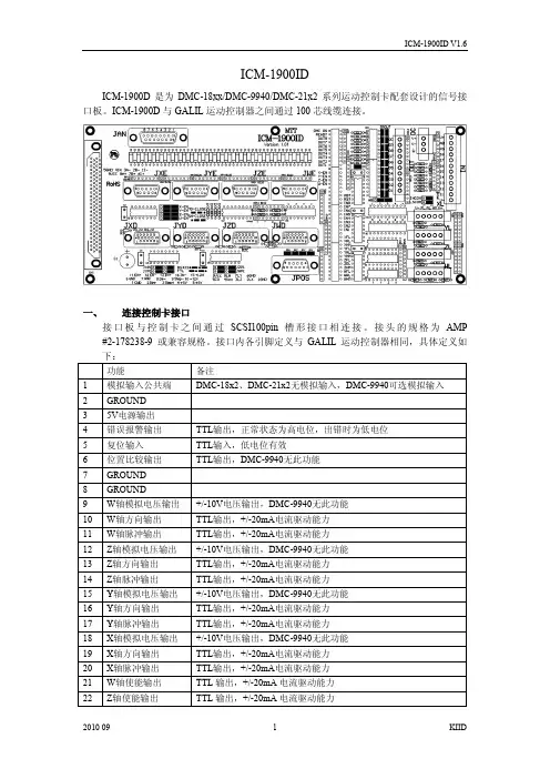
ICM-1900IDICM-1900D是为DMC-18xx/DMC-9940/DMC-21x2系列运动控制卡配套设计的信号接口板。
ICM-1900D与GALIL运动控制器之间通过100芯线缆连接。
一、连接控制卡接口接口板与控制卡之间通过SCSI100pin 槽形接口相连接。
接头的规格为AMP #2-178238-9 或兼容规格。
接口内各引脚定义与GALIL运动控制器相同,具体定义如二、编码器反馈信号接口编码器反馈信号接口接收5V编码器信号,可接收信号规格为TTL或RS422的旋转编码器、光栅尺以及伺服驱动器输出的类编码器信号。
建议采用差分输出的信号形式,并使用屏蔽双绞线传输编码器反馈信号。
如编码器不提供差分驱动,(只提供A、B、Index信号),GALIL也可接收,但此种信号本身极易受到干扰而使系统不能正常工作。
ICM-1900ID上编码器反馈信号接口为9孔D形接头(母),四轴的接口分别标注为:JXE、JYE、JZE、JWE。
在ICM-1900ID内部,对所有输入编码器信号进行了限压保护。
为便于用户连接编码器或光栅尺,在接口内提供了5V电源接口内引脚分配如下:INPUT 5A(6A/7A/8A):GALIL通用输入信号,为TTL电平信号,可选连接光栅尺状态输出信号(部分规格的光栅尺会提供报警信号)。
此引脚为TTL输入,悬空状态下为高电平,输入低电平为有效输入信号。
接口板内采用74LS07(U1)接收此信号。
如不需要从光栅尺/编码器接口接入此信号,请保持此引脚悬空,以避免引入干扰信号。
所有编码器输入采用如下保护电路,以避免由于外部干扰尖峰压导致GALIL控制器内部接收电路损坏。
三、电机放大器/驱动器接口电机放大器/驱动器接口提供用于控制电机放大/驱动器的控制信号,包括用于速度/电流控制的+/-10V 电压信号、用于位置控制的脉冲/方向信号、放大器使能信号以及可选的放大器报警信号。
ICM-1900ID上的电机放大器/驱动器接口为15孔高密度D形接头(母),四轴的接口分别标注为JXD、JYD、JZD、JWD。
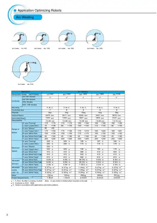
*1: F=Floor, W=Wall, C=Ceiling, S=Shelf (Note : S-axis motion is limited when mounted on the wall.)*2: Conforms to JIS B 8432.*3: Varies in accordance with applications and motion patterns.ApplicationArc Welding Manipulator Model (MOTOMAN -)VA 1400MA 1400MA 1800MA 1900MA 3100ControllerDX 100 Models NX 100 ModelsXRC ModelsNXC 100 Models Mounting *1F , W, C F , W, C F , W, C F , W, C F , W, CControlled Axis 76666Payload3kg3kg 15kg 3kg 3kg Vertical Reach 2475 mm2511 mm 3243 mm 3437 mm 5615 mm Horizontal Reach1434 mm 1434 mm 1807 mm 1904 mm 3121 mm Repeatability *2±0.08 mm±0.08 mm±0.08 mm±0.08 mm±0.15 mmRange ofMotion S -axis (Turning ) -170+170-170+170-180+180-180+180-180+180L -axis (Lower Arm ) -70+148-90+155-100+155-110+155-90+135E -axis (Elbow ) -90+90U -axis (Upper Arm ) -175+150-175+190-175+210-165+220-160+251R -axis (Wrist Roll ) -150+150-150+150-175+175-150+150-150+150B -axis (Wrist Pitch/Yaw) -45+180-45+180-45+180-45+180-45+180T -axis (Wrist Twist ) -200+200-200+200-200+200-200+200-200+200MaximumSpeedS -axis (Turning )220/s 220/s 195/s 197/s 180/s L -axis (Lower Arm )200/s 200/s 175/s 175/s 178/s E -axis (Elbow )220/sU -axis (Upper Arm )220/s 220/s 190/s 185/s 178/s R -axis (Wrist Roll )410/s410/s 380/s 410/s 400/s B -axis (Wrist Pitch/Yaw )410/s410/s 340/s 410/s 410/s T -axis (Wrist Twist )610/s 610/s 560/s 610/s 610/s Allowable MomentR -axis (Wrist Roll)8.8N m8.8N m 38.6N m 8.8N m 8.8N m B -axis (Wrist Pitch/Yaw )8.8N m8.8N m 38.6N m 8.8N m 8.8N m T -axis (Wrist Twist )2.9N m2.9N m 7.35N m 2.9N m 2.9N m Allowable R -axis (Wrist Roll )0.27kg m 20.27kg m 21.04kg m 20.27kg m 20.27kg m 2Inertia B -axis (Wrist Pitch/Yaw)0.27kg m 20.27kg m 21.04kg m 20.27kg m 20.27kg m 2(GD 2/4)T -axis (Wrist Twist )0.03kg m 20.03kg m 20.04kg m 20.03kg m 20.03kg m 2Mass 150kg130kg 380kg 280kg 501kg Power Requirements *31.5kVA1.5kVA2.5kVA2.0kVA2.5kVAApplication Optimizing Robots Arc WeldingMOTOMAN-VA 1400MOTOMAN -MA 3100MOTOMAN-MA 1400MOTOMAN-MA 1800MOTOMAN-MA 1900*1: F=Floor, W=Wall, C=Ceiling, S=Shelf (Note : S -axis motion is limited when mounted on the wall.)*2: Conforms to JIS B 8432.*3: Varies in accordance with applications and motion patterns.*4: When not used with an external cable.ApplicationSpot Welding Manipulator Model (MOTOMAN -)VS 50MS 80MS 120ES 165D ES 165RDES 200D ES 200RD ES 280DControllerDX 100 Models NX 100 ModelsXRC ModelsNXC 100 ModelsMounting *1F F F F S F S FControlled Axis 76666666Payload50kg80kg *4120kg 165kg *4165kg *4200kg *4200kg *4280kg Vertical Reach 2597 mm 3397 mm 2163 mm 3372 mm 4782 mm 3372 mm 4782 mm 3022 mm Horizontal Reach 1630 mm 2061 mm 1623 mm 2651 mm 3140 mm 2651 mm 3140 mm 2446 mmRepeatability *2±0.1 mm±0.07 mm ±0.2 mm ±0.2 mm±0.2 mm 0.2 mm±0.2 mm ±0.2 mm Range ofMotionS -axis (Turning )-180+180-180+180-150+150 -180+180-180+180-180+180-180+180-180+180L -axis (Lower Arm )-60+125-60+120-60+50-60+76-130+80-60+76-130+80-60+76E -axis (Elbow )-170+170U -axis (Upper Arm )-35+215-170+90-105+72 -142.5+230-112+208-142.5+230-107+208-142.5+230R -axis (Wrist Roll )-170+170-360+360*4-360+360-360+360*4-360+360*4 -360+360*4-360+360*4-360+360B -axis (Wrist Pitch/Yaw)-125+125-125+125*4-130+130-130+130*4-130+130*4 -125+125*4-125+125*4-125+125T -axis (Wrist Twist )-180+180-360+360*4-360+360-360+360*4-360+360*4-360+360*4-360+360*4-360+360MaximumSpeedS -axis (Turning )170/s 170/s 130/s 110/s 105/s 95/s 90/s *490/s L -axis (Lower Arm )130/s 140/s110/s 110/s105/s 90/s85/s *480/sE -axis (Elbow )130/sU -axis (Upper Arm )130/s 160/s 130/s 110/s105/s 95/s 85/s *490/s R -axis (Wrist Roll )130/s230/s 215/s 175/s 175/s 120/s 120/s 115/s B -axis (Wrist Pitch/Yaw )130/s230/s 180/s 150/s 150/s 120/s 120/s 110/s T -axis (Wrist Twist )200/s 350/s 300/s 240/s 240/s 190/s 190/s 190/s AllowableMomentR -axis (Wrist Roll )377N m392N m *4588N m 921N m *4921N m *41344N m *41344N m *41333N m B -axis (Wrist Pitch/Yaw )377N m392N m *4588N m 921N m *4921N m *41344N m *41344N m *41333N m T -axis (Wrist Twist )147N m196N m *4392N m 490N m 490N m 715N m 715N m 706N m A ll owab le R -axis (Wrist Roll )29.6kg m 228kg m 2*435kg m 285kg m 2*485kg m 2*4143kg m 2*4143kg m 2*4142kg m 2Inertia B -axis (Wrist Pitch/Yaw)29.6kg m 228kg m 2*435kg m 285kg m 2*485kg m 2*4143kg m 2*4143kg m 2*4142kg m 2(GD 2/4)T -axis (Wrist Twist )12.5kg m 211kg m 2*414.5kg m 245kg m 245kg m 280kg m 280kg m 279kg m 2Mass640kg 550kg 950kg 1100kg 1540kg 1130kg 1570kg 1120kg Power Requirements *35.0kVA 4.0kVA 4.5kVA 5.0kVA5.0kVA5.0kVA 5.0kVA 10kVAMOTOMAN -VS 50MOTOMAN -MS 80MOTOMAN -MS 120MOTOMAN -ES 165DMOTOMAN-ES 200DMOTOMAN-ES 200RDMOTOMAN-ES 280DMOTOMAN-ES 165RDApplication Optimizing Robots Spot WeldingApplicationMaterial Handling(General purpose)Manipulator Model (MOTOMAN -)HP 3JMH 5MH 5LMH 6MH 6SHP 20DHP 20D -6MH 50MH 50-20ControllerDX 100 ModelsNX 100 Models XRC Models NXC 100 Models*4*4Mounting *1F, W, CF , W, CF , W, CF , W, CF , W, CF, W, CF, W, CF , W, CF , W, CControlled Axis 666666666Payload 3kg 5kg 5kg 6kg 6kg 20kg 6kg 50kg 20kg Vertical Reach 804 mm 1193 mm 1560 mm 2486 mm 1597 mm 3063 mm 3459 mm 3578 mm 5585 mm Horizontal Reach 532 mm706 mm895 mm1422 mm997 mm1717 mm1915 mm2061 mm3106 mmRepeatability *2±0.03 mm ±0.02 mm ±0.03 mm ±0.08 mm ±0.08 mm ±0.06 mm ±0.06 mm ±0.07 mm ±0.15 mmRange of MotionS -axis (Turning )-160+160 -170+170 -170+170 -170+170 -170+170 -180+180 -180+180 -180+180 -180+180L -axis (Lower Arm) -85+90-65+150-65+150 -90+155 -80+133-110+155 -110+155-90+135 -90+135U -axis (Upper Arm) -105+260 -136+255 -138+255 -175+250 -130+165 -165+255 -160+255 -170+251 -160+251R -axis (Wrist Roll ) -170+170 -190+190 -190+190 -180+180 -180+180 -200+200 -200+200 -360+360 -190+190B -axis (Wrist Pitch/Yaw ) -120+120 -125+125 -125+125 -45+225 -45+225-50+230-50+230 -125+125-50+230T -axis (Wrist Twist) -360+360 -360+360 -360+360 -360+360 -360+360 -360+360 -360+360 -360+360 -360+360Maximum SpeedS -axis (Turning )200/s 376/s 270/s 220/s 220/s 197/s 197/s 180/s 180/s L -axis (Lower Arm )150/s350/s 280/s 200/s 220/s 175/s 175/s 178/s 178/s U -axis (Upper Arm )190/s 400/s 300/s 220/s 220/s 187/s 187/s 178/s 178/s R -axis (Wrist Roll )300/s 450/s 450/s 410/s 410/s 400/s 400/s 250/s 400/s B -axis (Wrist Pitch/Yaw )300/s 450/s 450/s 410/s 410/s 400/s 400/s 250/s 400/s T -axis (Wrist Twist)420/s 720/s 720/s 610/s 610/s 600/s 600/s 360/s 600/s Allowable Moment R -axis (Wrist Roll )5.39N m 12N m 12N m 11.8N m 11.8N m 39.2N m 11.8N m 216N m 39.2N m B -axis (Wrist Pitch/Yaw)5.39N m 12N m 12N m 9.8N m 9.8N m 39.2N m 9.8N m 216N m 39.2N m T -axis (Wrist Twist )2.94N m 7N m7N m5.9N m5.9N m19.6N m5.9N m147N m 19.6N m Allowable Inertia (GD 2/4)R -axis (Wrist Roll )0.1kg m 20.30kg m 20.30kg m 20.27kg m 20.27kg m 21.05kg m 20.24kg m 228kg m 21.05kg m 2B -axis (Wrist Pitch/Yaw)0.1kg m 20.30kg m 20.30kg m 20.27kg m 20.27kg m 21.05kg m 20.17kg m 228kg m 21.05kg m 2T -axis (Wrist Twist)0.03kg m 20.1kg m 20.1kg m 20.06kg m 20.06kg m 20.75kg m 20.06kg m 211kg m 20.75kg m 2Mass27kg28kg 30kg 130kg 120kg 268kg 273kg 550kg 495kg Power Requirements*30.5kVA1.0kVA1.0kVA1.5kVA1.5kVA2.0kVA2.0kVA4.0kVA3.5kVA*1: F=Floor, W=Wall, C=Ceiling, S=Shelf (Note : S-axis motion is limited when mounted on the wall.)*2: Conforms to JIS B 8432.*3: Varies in accordance with applications and motion patterns.*4: Only for handling.HandlingApplication Optimizing Robots MOTOMAN -HP 3J MOTOMAN-HP 20DMOTOMAN-HP 20D -6MOTOMAN-MH 50MOTOMAN-MH 50-20MOTOMAN-MH 5MOTOMAN-MH 5LMOTOMAN-MH 6MOTOMAN-MH 6SApplicationMaterial Handling(General purpose)Manipulator Model (MOTOMAN -)MH 80MH 165MH 200MH 215MH 250UP 350DUP 400RDUP 350D -500UP 350D -600ControllerDX 100 ModelsNX 100 Models XRC Models NXC 100 ModelsMounting *1F F F F F F S F FControlled Axis 666666666Payload 80kg 165kg *4200kg *4215kg 250kg 350kg 400kg 500kg 600kg Vertical Reach 3578 mm 3372 mm 3372 mm 3894 mm 3490 mm 2761 mm 4908 mm 2761 mm 2761 mm Horizontal Reach 2061 mm2651 mm2651 mm2912 mm2710 mm2542 mm3518 mm2542 mm2542 mmRepeatability *2±0.07 mm ±0.2 mm 0.2 mm ±0.2 mm 0.2 mm ±0.5 mm ±0.5 mm ±0.5 mm ±0.5 mmRange of Motion S -axis (Turning )-180+180 -180+180-180+180 -180+180 -180+180 -150+150 -150+150 -150+150 -150+150L -axis (Lower Arm)-90+135-60+76-60+76-60+76-60+76-55+61-122+20-55+61-55+61U -axis (Upper Arm ) -170+251 -142.5+230 -142.5+230 -142.5+230 -142.5+230-113+30-9+120-113+30-113+30R -axis (Wrist Roll ) -360+360 -360+360*4 -360+360*4 -360+360 -360+360 -360+360 -360+360 -360+360 -360+360B -axis (Wrist Pitch/Yaw ) -125+125 -130+130*4 -125+125*4 -125+125 -125+125 -125+125 -120+120 -125+125 -125+125T -axis (Wrist Twist ) -360+360 -360+360*4 -360+360*4 -360+360 -360+360 -360+360 -360+360 -360+360 -360+360Maximum SpeedS -axis (Turning )170/s 110/s 95/s 100/s 100/s 95/s 80/s 80/s 60/s L -axis (Lower Arm)140/s 110/s 90/s 90/s 90/s 95/s 80/s 80/s 70/s U -axis (Upper Arm )160/s 110/s 95/s 97/s 97/s 95/s 80/s 80/s 70/s R -axis (Wrist Roll )230/s 175/s 120/s 120/s 120/s 100/s 80/s 100/s 80/s B -axis (Wrist Pitch/Yaw )230/s 150/s120/s 120/s 120/s 100/s 80/s 100/s 80/s T -axis (Wrist Twist)350/s 240/s190/s190/s190/s 160/s 160/s 160/s 160/s Allowable Moment R -axis (Wrist Roll )392N m 921N m *41344N m *41176N m 1385N m 1960N m 1960N m 1960N m 2450N m B -axis (Wrist Pitch/Yaw)392N m 921N m *41344N m *41176N m 1385N m 1960N m 1960N m 1960N m 2450N m T -axis (Wrist Twist )196N m 490N m 715N m 710N m735N m 823N m 833N m 823N m 823N m Allowable Inertia (GD 2/4)R -axis (Wrist Roll )28kg m 285kg m 2*4143kg m 2*4317kg m 2317kg m 2150kg m 2150kg m 2150kg m 2200kg m 2B -axis (Wrist Pitch/Yaw)28kg m 285kg m 2*4143kg m 2*4317kg m 2317kg m 2150kg m 2150kg m 2150kg m 2200kg m 2T -axis (Wrist Twist)11kg m 245kg m 280kg m 2200kg m 2200kg m 290kg m 250kg m 290kg m 290kg m 2Mass555kg 1100kg 1130kg 1140kg 1130kg 2200kg 3600kg 2350kg 2400kg Power Requirements *34.5kVA5.0kVA5.0kVA6.0kVA6.0kVA5.5kVA12kVA5.5kVA7.0kVA*1: F=Floor, W=Wall, C=Ceiling, S=Shelf (Note : S-axis motion is limited when mounted on the wall.)*2: Conforms to JIS B 8432.*3: Varies in accordance with applications and motion patterns.*4: When not used with an external cable.MOTOMAN-MH 80MOTOMAN -MH 250MOTOMAN -UP 350D MOTOMAN -UP 400RDMOTOMAN -UP 350D -500MOTOMAN -UP 350D -600MOTOMAN-MH 165MOTOMAN-MH 200MOTOMAN-MH 215ApplicationPicking / Packing PalletizingManipulator Model(MOTOMAN -)MPK 2MPK 50MPL 80MPL 100MPL 160MPL 300MPL 500MPL 800ControllerDX 100 Models NX 100 ModelsXRC Models NXC 100 ModelsMounting *1F ,W,C F F F F F F FControlled Axis 54544444Payload2kg50kg 80kg 100kg 160kg 300kg 500kg 800kg Vertical Reach 1625 mm 1668 mm 3291 mm 3024 mm 3024 mm 3024 mm 3024 mm 3024 mm Horizontal Reach900 mm1893 mm 2061 mm 3159 mm 3159 mm 3159 mm 3159 mm 3159 mm Repeatability *2±0.5 mm±0.5 mm ±0.07 mm ±0.5 mm ±0.5 mm ±0.5 mm ±0.5 mm ±0.5 mm Range of MotionS -axis (Turning )-170+170-180+180-180+180-180+180 -180+180 -180+180 -180+180 -180+180L -axis (Lower Arm)-120+120-35+80-90+135-45+90-45+90-45+90-45+90-45+90U -axis (Upper Arm)-102+282-105+15-160+35-120+15.5-120+15.5-120+15.5-120+15.5-120+15.5R -axis (Wrist Roll )B -axis (Wrist Pitch/Yaw)-150+150 -15+15T -axis (Wrist Twist)-270+270 -350+350- 360+360-360+360 -360+360-360+360-360+360-360+360Maximum SpeedS -axis (Turning )320/s185/s 170/s 140/s 140/s 90/s85/s 65/s L -axis (Lower Arm )330/s215/s 170/s 140/s 140/s 100/s 85/s 65/s U -axis (Upper Arm )330/s215/s 170/s140/s 140/s110/s 85/s 65/sR -axis (Wrist Roll )B -axis (Wrist Pitch/Yaw )380/s 170/s T -axis (Wrist Twist )2000/s374/s350/s 305/s 305/s 195/s 195/s 125/sAllowableMoment R -axis (Wrist Roll )B -axis (Wrist Pitch/Yaw)3.5N m 78.4N m T -axis (Wrist Twist )1.5N m 20.5N m Allowable R -axis (Wrist Roll )Inertia B -axis (Wrist Pitch/Yaw)0.065kg m 216kg m 2(GD 2/4)T -axis (Wrist Twist)0.012kg m 25.5kg m 26.1kg m 280kg m 280kg m 2140kg m 2200kg m 2550kg m 2Mass75kg 670kg 550kg 1700kg 1700kg 1820kg 2300kg 2550kg Power Requirements *31.5kVA4.0kVA 4.0kVA9.5kVA9.5kVA 9.5kVA 9.5kVA 10kVA*1: F=Floor, W=Wall, C=Ceiling, S=Shelf (Note : S -axis motion is limited when mounted on the wall.)*2: Conforms to JIS B 8432.*3: Varies in accordance with applications and motion patterns.Picking / PackingPalletizingApplication Optimizing Robots MOTOMAN -MPK 2MOTOMAN -MPK 50MOTOMAN-MPL 80MOTOMAN -MPL 160MOTOMAN -MPL 300MOTOMAN -MPL 500MOTOMAN -MPL 800MOTOMAN-MPL 100ApplicationAssembly & Distributing Manipulator Model(MOTOMAN -)SIA 5D SIA 10D SIA 20DSIA 30D SIA 50DSDA 5D SDA 10D SDA 20DControllerDX 100 Models NX 100 ModelsXRC ModelsNXC 100 ModelsMounting *1F , W, C F, W, C F , W, C F F F , C F FDegrees of Freedom 77777151515Payload5kg 10kg 20kg 30kg 50kg 5kg/Arm 10kg/Arm 20kg/Arm Vertical Reach 1007 mm 1203 mm 1498 mm 2597 mm 2597 mm 1118 mm 1440 mm 1820 mm Horizontal Reach 559 mm 720 mm 910 mm 1485 mm 1630 mm 1604 mm 1970 mm 2590 mm Ripeatability*2±0.06 mm±0.1 mm±0.1 mm±0.1 mm±0.1 mm±0.06 mm ±0.1 mm ±0.1 mm Range of MotionRotation-170+170 -170+170 -180+180S -axis (Turning ) -180+180 -180+180-180+180 -180+180 -180+180 -90+270, -270+90 -180+180 -180+180L -axis (Lower Arm) -110+110 -110+110 -110+110 -125+125 -60+125 -110+110 -110+110 -110+110E -axis (Elbow ) -170+170 -170+170 -170+170 -170+170 -170+170 -170+170-170+170 -170+170U -axis (Upper Arm ) -90+115 -135+135 -130+130 -110+110 -35+215-90+115 -135+135 -130+130R -axis (Wrist Roll ) -180+180 -180+180 -180+180 -170+170 -170+170 -180+180 -180+180 -180+180B -axis (W rist Pitch/Yaw ) -110+110 -110+110 -110+110 -110+110 -125+125 -110+110 -110+110 -110+110T -axis (Wrist Twist) -180+180-180+180 -180+180 -180+180 -180+180-180+180 -180+180 -180+180Maximum SpeedRotation180/s 130/s 125/s S -axis (Turning )200/s 170/s130/s 130/s 170/s 200/s 170/s 130/s L -axis (Lower Arm )200/s170/s 130/s 130/s 130/s 200/s 170/s 130/s E -axis (Elbow )200/s170/s 170/s 130/s 130/s 200/s 170/s 170/s U -axis (Upper Arm )200/s 170/s 170/s 130/s 130/s 200/s 170/s 170/s R -axis (Wrist Roll )200/s 200/s 200/s 170/s 130/s 200/s 200/s 200/s B -axis (W rist Pitch/Yaw )230/s 200/s 200/s 170/s 130/s 230/s 200/s 200/s T -axis (Wrist Twist )350/s400/s 400/s 200/s 200/s 350/s 400/s 400/s AllowableMoment R -axis (Wrist Roll )14.7N m31.4N m 58.8N m 117.6N m 377N m 14.7N m 31.4N m 58.8N m B -axis (W rist Pitch/Yaw)14.7N m 31.4N m 58.8N m 117.6N m 377N m 14.7N m 31.4N m 58.8N m T -axis (Wrist Twist )7.35N m 19.6N m 29.4N m 58.8N m 147N m 7.35N m 19.6N m 29.4N m Allowable R -axis (Wrist Roll )0.45kg m 21.0kg m 24.0kg m 26.0kg m 229.6kg m 20.45kg m 21.0kg m 24.0kg m 2Inertia B -axis (W rist Pitch/Yaw)0.45kg m 21.0kg m 24.0kg m 26.0kg m 229.6kg m 20.45kg m 21.0kg m 24.0kg m 2(GD 2/4)T -axis (Wrist Twist )0.11kg m 20.4kg m 22.0kg m 23.0kg m 212.5kg m 20.11kg m 20.4kg m 22.0kg m 2Mass 30kg 60kg 120kg 345kg 640kg 110kg 220kg 380kg Power Requirements *31.0kVA1.5kVA2.2kVA 2.8kVA 5.0kVA1.4kVA2.7kVA4.4kVA*1: F=Floor, W=Wall, C=Ceiling, S=Shelf *2: Conforms to JIS B 8432.*3: Varies in accordance with applications and motion patterns.MOTOMAN-SIA 5DMOTOMAN-SIA 50DMOTOMAN-SDA 5DMOTOMAN-SDA 10DMOTOMAN-SDA 20DMOTOMAN-SIA 10DMOTOMAN-SIA 20DMOTOMAN-SIA 30DAssembly & DistributingApplication Optimizing RobotsApplicationPress Handling Manipulator Model (MOTOMAN -)EPH 130EPH 130REPH 130RLEPH 4000EP 4000NControllerDX 100 Models NX 100 ModelsXRC ModelsNXC 100 ModelsMounting *1F S S S SControlled Axis 66666Payload130kg 130kg 130kg 200kg 200kg Vertical Reach 3372 mm 3775 mm 4151 mm 2629 mm 2629 mm Horizontal Reach2651 mm3134 mm 3474 mm 3505 mm 3505 mm Repeatability *2±0.2 mm±0.2 mm ±0.3 mm ±0.5 mm ±0.5 mm Range of MotionS -axis (Turning ) -180+180 -180+180 -180+180 -150+150 -150+150L -axis (Lower Arm ) -60+76-130+70-130+70-122+25-122+25U -axis (Upper Arm ) -137.5+230-70+95-70+95-70+53-70+53R -axis (Wrist Roll ) -360+360 -360+360 -360+360 -360+360 -360+360B -axis (Wrist Pitch/Yaw) -130+130 -130+130 -130+130 -120+120 -120+120T -axis (Wrist Twist ) -360+360 -360+360 -360+360 -360+360-360+360Maximum SpeedS -axis (Turning )130/s 110/s 110/s 90/s 90/s L -axis (Lower Arm )130/s110/s 110/s 90/s 90/s U -axis (Upper Arm )130/s110/s 110/s 90/s 90/s R -axis (Wrist Roll )215/s 215/s 215/s 80/s 80/s B -axis (Wrist Pitch/Yaw )180/s180/s 180/s 80/s 80/s T -axis (Wrist Twist )300/s 300/s 300/s 160/s 160/s AllowableMomentR -axis (Wrist Roll )735N m735N m 735N m 1274N m 1274N m B -axis (Wrist Pitch/Yaw)735N m 735N m 735N m 2156N m 2156N m T -axis (Wrist Twist )421N m421N m 421N m 0N m 0N m Allowabl e R -axis (Wrist Roll )45kg m 245kg m 245-130kg m 2*484.5kg m 284.5kg m 2Inertia B -axis (Wrist Pitch/Yaw )45kg m 245kg m 245-130kg m 2*4330kg m 2330kg m 2(GD 2/4)T -axis (Wrist Twist )15kg m 215kg m 215-38kg m 2*480kg m 280kg m 2Mass 1495kg 1420kg 1445kg 3050kg 3100kg Power Requirements *310kVA 10kVA 10kVA 22kVA22kVA*1:F=Floor, W=Wall, C=Ceiling, S=Shelf (Note : S -axis motion is limited when mounted on the wall.)*2: Conforms to JIS B 84323.*3: Varies in accordance with applications and motion patterns.*4: Varies in accordance with load torque.Press HandlingApplication Optimizing Robots MOTOMAN-EPH 130MOTOMAN-EP 4000NMOTOMAN-EPH 130RMOTOMAN-EPH 130RLMOTOMAN-EPH 4000*1: F=Floor, W=Wall, C=Ceiling, S=Shelf (Note : S -axis motion is limited when mounted on the wall.)*2: Conforms to JIS B 8432.*3: Varies in accordance with applications and motion patterns.*4-130+90(S-axis -90+90)-130+30(S-axis +90+120)-130+30(S-axis -90-120)ApplicationPainting Manipulator Model (MOTOMAN -)EPX 1250EPX 2050PX 2750EPX 2700EPX 2800EPX 2800R EPX 2900ControllerDX 100 Models NX 100 ModelsXRC ModelsNXC 100 ModelsMounting *1F ,W,C F F W F S FControlled Axis 6666666Payload5kg 15kg 10kg 15kg 20kg 15kg 20kg Vertical Reach 1852 mm 2806 mm 3758 mm 5147 mm 4582 mm 4751 mm 4410 mm Horizontal Reach1256 mm 2054 mm 2729 mm 2700 mm 2778 mm 2825 mm 2900 mm Repeatability *2±0.15 mm±0.5 mm±0.5 mm±0.15 mm ±0.5 mm ±0.5 mm ±0.5 mm Range of MotionS -axis (Turning ) -170+170 -90+90 -150+150-125+25, -25+125 -150+150-120+120 -150+150L -axis (Lower Arm )-65+120 -50+100-40+90-65+140-45+120*4-50+110U -axis (Upper Arm )-165+205-163+5+10+168-65+90-85+90-70+90-70+90R -axis (Wrist Roll ) -190+190 -360+360 -260+260 -720+720-360+360 -360+360 -360+360B -axis (Wrist Pitch/Yaw) -145+145 -360+360 -270+270 -720+720-360+360 -360+360 -360+360T -axis (Wrist Twist ) -360+360 -360+360 -260+260 -720+720-360+360-360+360-360+360Maximum SpeedS -axis (Turning )185/s 2.0m/s 2.0m/s 2.0m/s 2.0m/s 2.0m/s155/s L -axis (Lower Arm )185/s 125/s U -axis (Upper Arm )185/s 155/s R -axis (Wrist Roll )360/s 450/s B -axis (Wrist Pitch/Yaw )410/s 550/s T -axis (Wrist Twist )500/s 650/s Allowable MomentR -axis (Wrist Roll )8.0N m 45.8N m 30.4N m 45.8N m 77.4N m 45.8N m 72.0N m B -axis (Wrist Pitch/Yaw)8.0N m 33.8N m 19.6N m 33.8N m 49.9N m 33.8N m 51.5N m T -axis (Wrist Twist )3.0N m 10.8N m 9.8N m 10.8N m 19.6N m 10.8N m 19.6N m Allowable R -axis (Wrist Roll )0.20kg m 21.45kg m 20.97kg m 21.45kg m 22.45kg m 21.45kg m 22.73kg m 2Inertia B -axis (Wrist Pitch/Yaw)0.20kg m 20.79kg m 20.40kg m 20.79kg m 21.20kg m 20.79kg m 21.63kg m 2(GD 2/4)T -axis (Wrist Twist )0.07kg m 20.10kg m 20.10kg m 20.10kg m 20.20kg m 20.10kg m 20.20kg m 2Mass110kg 540kg 560kg 590kg 650kg 820kg 1030kg Power Requirements*31.5kVA5.0kVA 5.0kVA 5.0kVA5.0kVA 5.0kVA5.0kVAType L Type RMOTOMAN -EPX 1250MOTOMAN -EPX 2800MOTOMAN -EPX 2800R MOTOMAN -EPX 2900MOTOMAN -EPX 2050MOTOMAN -PX 2750MOTOMAN -EPX 2700PaintingApplication Optimizing RobotsControllersController ModelDX 100DX 100(Assembly & Distributing )NX 100NXC 100Manipulator Model Small Model VA 1400, MA 1400, MA 1900MA 3100, MH 5, MH 5L, MH 6, MH 6S, HP 20D, HP 20D -6, MPK 2SIA 5D, SIA 10D, SIA 20DHP 3J, MH 5, MH 5LLarge Model MA 1800, VS 50, MS 80, MS 120, ES 165D, ES 165RD, ES 200D,ES 200RD, ES 280D *2, MH 50, MH 50-20, MH 80, MH 165, MH 200,MH 215*2,MH 250*2, UP 350D, UP 400RD, UP 350D -500, UP 350D -600, MPK 50*2, MPL 80*2, MPL 100*2, MPL 160*2, MPL 300*2, MPL 500*2, SIA 30D, SIA 50DSDA 5D, SDA 10D, SDA 20D EPH 130, EPH 130R,EPH 130RL, EPH 4000,EP 4000N Dimensions(W ×H ×D )Small Model425×1200×450 mm (Possible to control 3 external axes )500×580×580 mm (Possible to control 1 external axes )500×1200×500mm (Possible to control 2 external axes )485×183×300 mm (Possible to control 1 external axes )Large Model425×1200×450 mm (Possible to control 2 external axes )500×880×580 mm (Possible to control 1 external axes )600×1200×550 mm(Possible to control 2 external axes)Approximate Mass Small Model100kg 100kg 100kg 16kg Large Model 100kg *2150kg 150kg IEC Protection Class IP 54IP 54IP 51IP 20Dimensions (W ×H ×D )169×314.5×50 mm 169×314.5×50 mm 199×338×60 mm 199×338×60 mm Approximate Mass 0.990kg 0.990kg 1.320kg 1.320kg IEC Protection Class IP 65IP 65IP 65IP 65External Interface CF slot ×1USB Port (1.1)×1CF slot ×1USB Port (1.1)×1CF slot ×1CF slot ×1Number of Controlled Manipulators Up to 8 manipulators Up to 8 manipulators Up to 4 manipulators Up to 4 manipulators Number of Controlled Axes Up to 72 axes Up to 72 axes Up to 36 axes Up to 36 axesNumber ofJOBs Robot 16 JOBs 16 JOBs 8 JOBs 8 JOBs System 4 JOBs 4 JOBs 4 JOBs 4 JOBs Up to 32 groups Up to 32 groups Up to 16 groups Up to 16 groups Robot Up to 8 groups (R 1 to R 8)Up to 8 groups (R 1 to R 8)Up to 4 groups (R 1 to R 4)Up to 4 groups (R 1 to R 4)Base Up to 8 groups (B 1 to B 8)Up to 8 groups (B 1 to B 8)Up to 4 groups (B 1 to B 4)Up to 4 groups (B 1 to B 4)Station Up to 24 groups (S 1 to S 24)Up to 24 groups (S 1 to S 24)Up to 12 groups (S 1 to S 12)Up to 12 groups (S 1 to S 12)JOB CapacityJOB :200000 steps Robot command :10000 steps JOB :200000 steps Robot command :10000 steps JOB :60000 steps Robot command :10000 steps JOB :60000 stepsRobot command :10000 stepsCIO Ladder 20000 steps 20000 stepsStandard :10000 steps Extension :15000 steps Standard :10000 stepsExtension :15000 stepsI/OSystem Input :2048(max.)System Output :2048(max.)System Input :2048(max.)System Output :2048(max.)System Input :1024(max.)System Output :1024(max.)System Input :1024(max.)System Output :1024(max.)Number of JOB NamesUp to 32 digitsUp to 32 digitsUp to 8 digitsUp to 8 digits*1: These specifications and dimensions are for standard specifications and they are subject to change due to the optional installation.*2: When manipulator is ES 280D, MH 215, MH 250, MPK 50, MPL 80, MPL 100, MPL 160, MPL 300, and MPL 500, the regenerative resistor box (120 mm in depth, 50kg ) is mounted on the surface of the backside of the controller. Note : Contact YASKAWA regarding the dimension of the controller for MPL 800.Standard Specifi cations of Controller*1Small modelSmall model(for single -arm robots )Small modelLarge modelLarge model (for dual -arm robots)Large model DX 100NXC 100DX 100(Assembly & Distributing)NX 100Co n t r o l l e rs Pr o g r a m m i n g Pe n d a n t So f t w a r e Number of Controlled GroupsController Model NX 100(Painting )XRC (Painting )ManipulatorModel Standard Pendant EPX 2050, EPX 2700, EPX 2800, EPX 2800R, EPX 2900PX 2750Explosion-proof PendantEPX 2050, EPX 2700, EPX 2800, EPX 2800R, EPX 2900PX 2750Dimensions(W ×H ×D )Standard Pendant974×1200×600 mm(Possible to control 3 external axes )974×900×600 mm(Possible to control 3 external axes)Explosion-proof Pendant 974×1200×600 mm(Possible to control 3 external axes )974×1300×600 mm(Possible to control 3 external axes)Approximate Mass Standard Pendant 250kg 100kg Explosion -proof Pendant 250kg 200kg IEC Protection Class IP 41(Option : IP 54)IP 41Dimensions (W ×H ×D )Standard Pendant 199×338×60 mm 200×325×77 mm Explosion -proof Pendant 235×203×78 mm211×382×75 mmApproximate MassStandard Pendant1.32kg 1.2kgExplosion-proof Pendant 1.25kg 2.0kg IEC Protection Class IP 65IP 40External InterfaceCF slot ×1Standard RS 232C for Backup Explosion -proof N/ANumber of Controlled Manipulators Up to 4 robots Up to 3 robots Number of Controlled Axes Up to 36 axesUp to 27 axesNumber of JOBs Robot 8 JOBs 6 JOBsSystem4 JOBsUp to 16 groupsUp to 8 groupsRobot UP to 4 groups (R 1 to R 4)UP to 3 groups (R 1 to R 3)Base UP to 4 groups (B 1 to B 4)UP to 3 groups (B 1 to B 3)StationUP to 12 groups (S 1 to S 12)UP to 6 groups (S 1 to S6)JOB Capacity 60000 steps 10000 steps60000 steps 10000 steps CIO Ladder Standard :10000 steps Extension :15000 steps 1500 stepsI/OSystem Input :1024(max.)System Output :1024(max.)System Input :256(max.)System Output :256(max.)Number of JOB NamesUp to 8 digitsUp to 8 digits*: These specifications and dimensions are for standard specifications and they are subject to change due to the optional installation.Note : Contact YASKAWA regarding the dimension of the controller for EPX1250.Standard Specifi cations of Controller *Standard pendant model Standard pendant modelExplosion -proof pendant model Explosin -proof pendant modelNX 100(Painting )XRC (Painting )For PaintingCo n t r o l l e r s So f t w a r e Pr o g r a m m i n g Pe n d a n t Number of Controlled Groups。

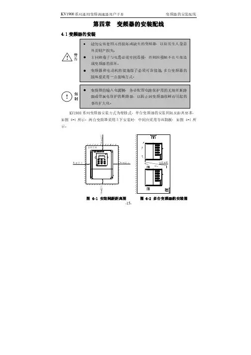
第四章第四章 变频器的安装配线变频器的安装配线变频器的安装配线4.1变频器的安装变频器的安装-16--17-②变频器的安装尺寸表(如下表4-1所示)-18--19-表4-1变频器安装尺寸表变频器安装尺寸表变频器型号变频器型号 G :恒转矩负载恒转矩负载 P :风机水泵负载风机水泵负载A (㎜)B (㎜) L (㎜) L1L1 (㎜) W (㎜)H (㎜)安装安装 孔径(㎜)外形外形 图号图号 毛重(kg )KV1900-G0007C-4T KV1900-G0015C-4T KV1900-G0022C-4T KV1900-G0004C-2S KV1900-G0007C-2S KV1900-G0015C-2S KV1900-G0004C-2T KV1900-G0007C-2T 108 175 1481561181855.5图4-5 2.5KV1900-G0037C-4T KV1900-G0055C-4T KV1900-P0055C-4T KV1900-G0022C-2S KV1900-G0015C-2T KV1900-G0022C-2T140 222 1541651502325.5图4-544.3变频器的配线变频器的配线 4.3.1注意事项注意事项::-20--21-4.3.2变频器端子说明及配线变频器端子说明及配线1、 主回路端子功能说明(见下表4-2)表4-2主回路端子功能说明主回路端子功能说明2、 主回路端子:端子R 、S 、T 及L 1、L 2接线示意图R S T 三相交流电源L1L2单相交流电源(单相单相220220220VA C VA C))(三相三相380380380//220220VAC VAC VAC))-22-3、 主回路端子:端子U 、V、W 及P+、DB 接线示意图P+DBU V W交流电动机制动电阻4、 主回路端子:端子G接线示意图G5、控制回路端子示意图图4-10控制回路端子控制回路端子功能说明见下表-23--24-表4-3控制回路端子功能说明控制回路端子功能说明类别 端子端子 标号标号 功能说明功能说明电气规格电气规格 内部电路内部电路FWDFWD-COM 之间短接时正转,开路时减速并停止 运行控制端子 RE V RE V -COM 之间短接时反转,开路时减速并停止 INPUT ,0~24V 电平信号,低电平有效,1m A X 1 X 2 X3 多功能输入端子X 4Xn (n=1,2,3,4)-COM 之间短接时有效,其功能分别由参数F 051~F 054设定INPUT ,0~24V 电平信号,低电平有效,1m AY 1多功能可编程集电极开路输出1,可编程定义为多种功能的开关量输出端子,参考地为COM OUTPUT ,最大负载电流I≤50m AV模拟电压信号输入1路,参考地为GNDINPUT ,0~10V 直流电压输入输出端子I模拟电流信号输入1路,参考地为GNDINPUT ,0~20m A (4~20m A)直流电流-25-类别 端子端子 标号标号 功能说明功能说明 电气规格电气规格 内部电路内部电路AM多功能可编程模拟电压输出,参考地为GNDOUTPUT ,0~10V 直流电压 输入输出端子FM多功能可编程频率输出,参考地为GND OUTPUT ,0~20kHz ,脉冲信号TATB故障输出端子TC故障继电器接点输出检测变频器保护功能的动作,变频器正常时:TA -TB 闭合,TA -TC 断开;变频器因故障而保护动作时:TA -TB 断开,TA -TC 闭合 触点额定值: 250V AC -3A (ϕcos =1) 250V AC -1A (ϕcos =0.4)30V DC -1AP 24 24V DC 电源输出(控制电源)COM 24V DC 电源的地端子 24V DC -100m AV RF10V DC 电源输出电源接口GND10V DC 电源的地端子10V DC -50m AA+RS 485信号+端通讯接口A -RS 485信号-端标准RS 485信号-26-6、 变频器的基本配线图①三相交流220V或三相交流380V 输入基本配线图适用机型:KV1900-G 0007C -4T~KV1900-G 0055C/P 0055C -4TKV1900-G 0004C -2T~KV1900-G 0022C -2T②单相交流220V 输入基本配线图适用机型:KV1900-G 0004C -2S~KV1900-G 0022C -2S-27--28-①三相交流220V 或三相交流380V 输入变频器外围配线图图 4-13变频器与选配器的连接一适用机型: KV1900-G 0007C -4T~KV1900-G 0037C/P 0055C -4TKV1900-G 0004C -2T~KV1900-G 0022C -2T②单相交流220V输入变频器外围配线图图 4-14变频器与选配器的连接二适用机型:KV1900-G0004C-2S~KV1900-G0022C-2S-29--30-。

FANUC机器人操作说明书1.概要………………………………………………………… (3)2.坐标系………………………………………………………… (7)3.程序创建…………………………………………………………114.动作指令…………………………………………………………125.焊接指令…………………………………………………………166.摆动指令…………………………………………………………187.寻点指令…………………………………………………………20概要•机器人•控制装置•示教器机器人机器人是由通过伺服电机驱动的轴和手腕构成的机构部件。
手腕叫做机臂,手腕的接合部叫做轴杆或者关节。
最初的3轴(J1.J2.J3)叫做基本轴。
机器人的基本构成,由该基本轴分别由几个直动轴和旋转轴构成而确定。
机械手腕轴对安装在法兰盘上的末端执行器(焊枪)进行操控。
如进行扭转、上下摆动、左右摆动之类的动作。
机械臂控制装置机器人控制装置,由电源装置、用户接口电路、动作控制电路、存储电路、I/O电路等构成。
用户在进行控制装置的操作时,使用示教操作盘和操作箱。
动作控制电路通过主cpu印刷电路板,对用来操作包含附加轴在内的机器人的所有轴之伺服放大器进行控制。
示教操作盘与菜单相关的键控开关与JOG相关的键控开关与执行相关的键控开关与编辑相关的键控开关2.坐标系坐标系是位确定机器人的位置和姿势而在机器人或空间上进行定义的位置坐标系统。
坐标系有关节坐标系、关节坐标系关节坐标系是设定在机器人的关节中的坐标系。
关节坐标系中的机器人的位置和状态,以各关节的底座侧的关节坐标系为基准而确定。
下图中的关节坐标系的关节值,处在所有轴都为0°的状态.关节坐标系刀具坐标系这是用来定义刀尖点(TCP)的位置和刀具姿势的坐标系.刀具坐标系必须事先进行设定.位定义时.将由机械接口坐标系代替刀具坐标系。
世界坐标系世界坐标系,是被固定在空间上的标准笛卡尔坐标系,其被固定在机器人事先确定的位置。
数字卫星寻星仪使用说明书尊敬的顾客:感谢您选择我们的系列数字卫星寻星仪。
如果您是初次使用本产品的用户请仔细阅读本使用手册,并妥善保管以便日后用作参考。
本手册中所载技术规格和操作方法可能改变,恕不另行通告。
第一次使用之前仪器要充满电。
(建议第一次充电4小时,但不要超过6小时)警告:本产品采用锂聚合物电池为其供电,请不要将其置入高温、高湿环境,更不要将其至于火中,对于由于不当操作行为造成的损失,本公司不担负责任。
请不要擅自拆卸本仪器的任何部分,机身内没有用户可维修的部件,需要维修时请联系授权的维修人员,或邮寄给我们。
机器使用时请首先输入使用地经纬度,输入方法见操作说明。
目录简介...............................................4注意事项...........................................4电池的注意事项.....................................5充电器的注意事项...................................5清洁和维护.........................................6免责声明...........................................6功能介绍...........................................7一、屏幕显示内容介绍................................7(1)、角度计算区....................................7(2)、参数设置区....................................8(3)、自定义频道表和当地卫星频道表序号区............8(4)、经纬度设置和功能显示区........................9(5)、测量区.......................................9二、面板介绍.....................................10三、仪器首次使用.................................111、利用OUTPUT端口供电...........................122、开机和关机....................................133、输入当前坐标..................................13四、手动寻星.....................................151、输入参数......................................152、测量信号......................................163、搜索信号......................................16五、利用内置当地频道表寻星.......................18六、利用自定义频道表寻星.........................18七、将当地频道表某个参数调入到自定义频道表内.....19八、修改当地频道表和自定义频道表参数并保存.......19九、删除自定义频道表参数内容.....................20十、恢复出厂设置.................................20十一、技术参数...................................20十二、.随机附件..................................21十三、中国城市坐标...............................22简介:我公司数字卫星寻星仪,能够帮助您方便和快捷地完成卫星天线安装定位,该仪器信号响应速度快,弱信号时也能够显示S/N比,判断信号是否存在。

HRM1900A立式磨使用手册合肥水泥研究设计院合肥中亚水泥机械厂二○○一年七月目录第一部分 HRM1900A立式磨安装一前言二技术参数及性能三结构及工作原理四设备安装五液压及润滑系统的酸洗安装第二部分 HRM1900A立式磨调试及使用一前言二磨机分部件试运行三立式磨整机空负荷试运行四立式磨带负荷试运行五人员培训六磨机操作七可能出现的问题及解决办法第三部分 HRM1900A立式磨维护及检修一前言二磨机的维护保养及检修三润滑表四易损件表第四部分图纸一 HRM1900A立式磨总图二 HRM1900A立式磨基础图三 HRM1900A立式磨下壳体磨盘安装图四 HRM1900A立式磨减速机电机安装图五 HRM1900A立式磨加压、检修油缸安装图六 HRM1900A立式磨分离器检修图七 HRM1900A立式磨磨辊装置检修图八 HRM1900A立式磨液压系统原理图九液压管路连接示意图第一部分 HRM1900A立式磨安装一前言HRM1900A立式磨是合肥水泥研究设计院下属合肥中亚水泥机械厂荣誉产品。
该型立式磨经多年生产实践考验,产品性能不断提高,逐步跨入国际同类产品先进行列,深得广大国内外用户青睐。
HRM1900A立式磨是一种技术性能优异的烘干兼粉磨设备,主要用于水泥生料的粉磨,可广泛应用于建材、轻工、化工、火力发电等行业。
该型立式磨具有粉磨效率高、电耗低、入料粒度大、产品细度易于调节、设备工艺流程简单、占地面积小、噪音低、扬尘小、使用维护简单、运行费用低、耐磨材料消耗少等优点。
除此之外,该型立式磨还具有如下独特性能:1.磨辊可用液压装置翻出机外,更换辊套衬板及磨机检修空间大,检修作业十分方便。
2.磨辊辊套能翻面使用,延长了耐磨材料的使用寿命。
3.开机前无需在磨盘上布料,并且磨机可空载启动,免除开机难的烦恼。
4.采用磨辊限位装置,避免磨机工作时间因断料而产生的剧烈震动。
5.采用新型磨辊密封装置,密封更加可靠,并且无需密封风机。
Uses future proof frequencies UHF 863.00 - 865.00MHz frequency band SMT technology Preset 16 channel PLL system Frequency stabilisation: < ±30ppm Dynamic range: > 100dB Total harmonic distortion: < 0.5% Frequency response: 40Hz-15KHz ±3dB Power consumption: 100mA Signal to noise ratio: > 100dBImage & spurious rejection: > 80dB Border upon channel rejection: > 80dB Receiving sensitivity: 5dBuV (SINAD=30dB) De-emphasis: 50us 4 different Kam KWM1900 kits available: Hand held mic system | Wireless headset system | Bodypack system | Instrument/guitar bug system M A N U A L V E R S I O N 2.0 22-11-11 For the latest instruction manual updates and information on the entire Kam range visit: Kam products are manufactured by: Lamba plc , Unit 1, Southfields Road, Dunstable, Bedfordshire, United Kingdom LU6 3EJ Telephone: (+44) (0)1582 690600 • Fax: (+44) (0)1582 690400•Email:*****************•Web: If this product is ever no longer functional please take it to a recycling plant for environmentally friendly disposal.Thank you for purchasing this Kam product, we are sure that it will serve you for many years to come.To optimise the performance of this product, please read these operating instructions carefully to familiarise yourself with the basic operations of this unit. Please retain them for future reference.This unit has been tested at the factory before being shipped to you.To prevent or reduce the risk of electrical shock or fire, do not expose the unit to rain or moisture. To prevent a fire hazard, do not expose the unit to any naked flame sources. Unplug this apparatus during lightning storms or if it is unlikely to be used for long periods of time.When installing the unit, please ensure you leave enough space around the unit for ventilation. Slots and openings in the unit are provided for ventilation to ensure reliable operation of the product and to protect it from overheating. To prevent fire hazard, the openings should never be blocked or covered.Always handle the power cable by the plug. Never pull out the plug by pulling on the cable. Never touch the power cable when your hands are wet as this could cause an electric shock. Do not tie a knot in the cable. The power cable should be placed such that it is not likely to be stepped on. A damaged power cable can cause a fire or give you an electrical shock. Check the power cord periodicaly, if you ever find that it is damaged, replace it before using the unit again. Contact your retailer for a replacement.The voltage of the available power supply differs according to country or region. Be sure that the power supply voltage of the area where this unit is to be used meets the required written on the unit.The lightning flash symbol inside a triangle is intended to alert the user to the presence high voltage within the unit’s enclosure that may be of sufficient power to constitute a risk of electrical shock to persons.Caution: to prevent the risk of electric shock, do not attempt to open the unit. No user-serviceable parts inside. Refer all servicing to qualified service personnel.The exclamation mark inside a triangle is intended to alert the user to the presence of important operating and maintenance instructions in the literature accompanying the appliance.Any modification carried out on the unit may invalidate the unit’s warranty.If applicable, only use the stand, tripod or bracket specified or sold with the apparatus.Select the installation location of your unit carefully. Avoid placing it in direct sunlight or locations subject to vibration and excessive dust. Do not use the unit where there are extremes in temperature (below 41ºF / 5ºC or exceeding 95ºF / 35ºC).Unpacking and safety: Please unpack your new product carefully, your new product should reach you in perfect condition. Please check that no damage has occurred during transit. If any damage is found, do not operate your unit. Please contact the retailer you purchased it from immediately. If there is any damage to the mains cable do not use the device. Always disconnect the unit from the mains supply when carrying out any servicing or cleaning of the unit.The serial number for this equipment should be located on the rear or underside of the unit. Please make a note of this number as you will need it for your warranty, it is a good idea to keep a copy of the serial for your own records.Kam KWM1900 featuresUses the UHF 863.00 - 865.00MHz band to avert frequency interference Automatic frequency scan searches for available frequenciesPLL system, preset 16 non-interference channelsSMT technologyThe receiver uses one 1.5V AA batteryThe hand held microphone uses a single 1.5V AA batteryIdeal working distance is up to 30 metresEasy to use and portable - the receiver connects directly to an audio mixer or amp Ideally suited for:Aerobics instructorsVocalists & singersPublic speakersZumba instructorsDance instructorsMusicals & theatreSchools & collegesDJs & musiciansAuctioneersVideo & film makersFeatures of the KWM1900 receiver1. Power switch2. Volume control3. Antenna4. Power supply LED indicator5. Signal and audio indicator6. Battery cover7. ACT button8. Channel select switch9. ACT IR10. Receiver output plugBattery compartment cover removalPairing the receiver with your transmitter (hand held mic or headset or bodypack or guitar bug)1. Open the receiver’s battery cover and insert a single 1.5 AA battery.2. Insert the correct battery (or batteries) in the transmitter (hand held mic or headset or bodypack or guitar bug).3. Switch the receiver ON using the power switch.4. Choose the channel frequency you wish to use with the dipswitches on the receiver (see below chart).5. Switch the transmitter ON using its power switch and remove any battery compartment covers that mayobscure the ACT IR.6. Press the ACT button on the receiver while simultaneously pointing the receiver’s ACT IR closely towards the transmitter’s ACT IR. Keep pressing the button until the light on the receiver goes green.7. The receiver light will only turn green when it matches the same frequency as the transmitter.8. Replace all battery compartment covers that you have removed to pair the devices.9. The receiver and transmitter are now paired and will work together.Channel frequency chart with dipswitch positionsWhen you have paired the receiver with your system’s transmitter you need to plug the receiver into a mic input via the ¼ inch jack plug and set your audio level.Hand held microphone (if supplied with your system)Ensure that the ON switch is engaged whilst you are pairing the devices. Once paired, the mic is ready to use. Headset microphone (if supplied with your system)Ensure that the ON switch is engaged whilst you are pairing the devices. Once paired, the mic is ready to use. Place the headset over your ears and adjust the microphone so that is in front of your mouth.Guitar (instrument) bug (if supplied with your system)Ensure that the ON switch is engaged whilst you are pairing the devices. Once paired, the bug is ready to use. Insert the jack plug into the output jack socket of your guitar/instrument and adjust the volume to suit. Bodypack (if supplied with your system)Ensure that the ON switch is engaged whilst you are pairing the devices. Once paired, the bodypack is ready to use. Insert your chosen microphone or instrument lead into the audio socket of the bodypack and adjust the volume to suit.1. Grille2. Power supply LED indicator3. Power switch4. Battery compartment cover5. ACT IR6. Battery compartmentFeatures of the KWM1900 headset microphone (if supplied with your system)1. Power switch2. Antenna3. ACT IR (shown with battery cover removed)4. Battery compartment5. Power supply LED indicator6. Microphone1. Battery compartment2. Antenna3. Power switch4. 15dB pad switch5. ¼ inch jack instrument insert6. Power supply LED indicator7. ACT IR (not shown)Features of the KWM1900 bodypack (if supplied with your system)1. Antenna2. Battery compartment3. Audio/microphone input4. Power supply LED indicator5. Power switch6. Volume control knob7. ACT IR (not shown)8. Lavalier microphone (not shown)9. Headset microphone (not shown)10. Instrument lead (not shown)SpecificationComprehensive performanceCarrier frequency UHF 863.00 - 865.00MHz Frequency stabilisation Less than ±30ppm Dynamic range More than 100dBTotal harmonic distortion Less than 0.5% Frequency response 40Hz-15KHz ±3dBAudio output level Mix type: 0 - ±400mVFixed receiverConsume power 100mASignal/noise ratio More than 100dBImage & spurious rejection More than 80dBBorder upon channel rejection More than 80dB Receiving sensitivity 5dBuV (SINAD=30Db)De-emphasis 50usHanding microphoneTransmitter power 30mAModulation type FMMax deviation ±40KHzSpurious emission More than 60dB (with carrier) Battery voltage 1.5 x 1Continuous usage Approx.5 hoursBodypack microphoneTransmitter power 30mAModulation type FMMax deviation 25KHzSpurious emission More than 40dB (with carrier) Battery voltage 1.5 x 2Continuous usage Approx.6 hoursAlways use high quality branded batteries.。
5000 Series1900 WPowerCyclone 7Allergy H13 filterTriActive nozzleFC9570/61Maximum performance with PowerCyclone 7Easy and hygienic dust disposalThe Philips Bagless Vacuum 5000 Series is our most powerful compact vacuum.Achieve maximum deep cleaning results with minimum effort thanks toPowerCyclone 7 technology and TriActive nozzle which features 3 cleaning actionsin one.Superior performancePowerful 1900W motor for high suction powerPowerCyclone 7 keeps strong suction power for longerTriActive nozzle for 3-way thorough cleaning actionPower control function to adjust suction powerAllergy H13 filter system captures >99.9% of fine dustEffortless cleaningCompact design with front and top handle for easy carryingDust container designed for hygienic emptying with one handSoft brush integrated into handle & furniture nozzleSoft bumper and rubber wheels to protect furnitureHighlightsPowerful 1900W motor1900W motor generates up to 410W of high suction power for powerful performance and deep cleaning results.PowerCyclone 7 TechnologyPowerCyclone 7 technology features anaerodynamic design to minimize air resistance and ensure sustained strong suction power.Super accelerated air flow in the cylindrical chamber and unique exit blades effectively cut out the dust from the air.TriActive nozzleTriActive nozzle utilizes 3 cleaning actions in one go. The specially designed soleplate removes dust from deep within carpets, while the large front opening sucks up big bits. Air channels and brushes on both sides of the nozzle pick up any dust and dirt alongside walls or furniture.Power controlPower control function easily adjusts suction for different cleaning tasks, from hard floors to soft furnishings.Compact and lightweightCompact and lightweight design ensure both storing and lifting the vacuum is easy. The design includes top and front handles for effortless carrying.Hygienic dust disposalEasy-to-empty dust container is designed for hygienic disposal with one hand, to help minimize dust cloud.Brush & furniture nozzleDusting brush tool is built into the handle so it's always ready to use on furniture, flat surfaces and upholstery. Furniture nozzle isdesigned for optimal cleaning of softfurnishings like cushions, couches and arm chairs, even removing pet hair.Allergy H13 filterAllergy H13 filter system catches >99.9% of fine dust particles - including pollen, pet hair and dustmites - ideal for allergy sufferers.Filtration level is equivalent to HEPA 13*.Soft bumper and rubber wheelsSoft bumper and rubber wheels protect furniture and prevent floor scratches while being easy tomaneuver around your home.2 years warrantyThe warranty period for this product is 24monthsDeveloped in EuropeManufactured to Philips' highest quality standards.SpecificationsPerformanceInput power (IEC): 1700 WInput power (max): 1900 WSound power level: 72-82 dBSuction power (max): 410 WUsabilityAction radius: 9 mCarrying handle: Top and frontTube type: Metal 2-piece telescopic tube Wheel type: RubberTube coupling: ActiveLockPower control: Electronic on appliance DesignColor: Dark Royal BlueFiltrationDust capacity: 1.5 LExhaust filter: Allergy H13 filterMotor filter: Washable filterFiltration level: HEPA13 level*Nozzles and accessoriesAccessories included: Crevice tool, IntegratedbrushAccessory storage: On tubeclipAdditional nozzle: Furniture nozzleStandard nozzle: TriActive nozzleExtra accessories: Filter replacement:FC8010/02SustainabilityPackaging: > 90% recycled materialsUser manual: 100% recycled paperWeight and dimensionsDimensions of product (LxWxH): 412 x 280 x280 mmWeight of product: 5 kg* Filtration levels are tested according EN60312-1-2017and are equivalent to HEPA 13.© 2020 Koninklijke Philips N.V.All Rights reserved.Specifications are subject to change without notice. Trademarks are the property of Koninklijke Philips N.V. or their respective owners.Issue date 2020‑10‑06 Version: 6.3.1。
ZJ1900A使用说明同杰克电脑钉扣机百福电控7.04 操作板操作板用于选取缝纫程序、更改参数值、控制不同的运行状态,以及用于阅读错误报告和服务设置。
操作板由一个带有相应显示的屏幕1和一系列功能键组成。
7.04.01 屏幕显示根据不同的运行状态,显示屏1上显示出有关机器状态、程序选择、顺序程序的进展、输入参数,以及错误报告的信息。
?已经起动的功能由一个三角形符号2在相应的功能键下面,或者旁边标出。
?根据具体的运行情况,用相应的图标及文字显示各种重要的数据,并且能直接进行更改(例如,转速3连同数值5)。
?在参数输入时,显示出所选的参数号及其所属的参数值,见11.03章,参数输入。
?在起动操作方式输入之后,在屏幕的上边显示出文字4("TE"),此时操作方式输入已活跃,见第11章,输入。
?当缝纫运行出现故障时,在屏幕上会显示出相应的错误报告,见校验说明的14.33章,屏幕上的错误报告。
?当缝纫运行出现故障时,在屏幕上会显示出相应的错误报告,见校验说明的14.33章,屏幕上的错误报告。
7.04.02 屏幕上的图标程序号,在此图标下显示出现时的缝纫程序号。
转速,在此图标下给出现时的转速。
尺度系数X(横向),在此图标下以,的形式给出X方向的尺度系数。
尺度系数Y(机臂纵向),在此图标下以,的形式给出Y方向的尺度系数。
底线计数器,件计数器,在此图标下给出现时的件数及底线数。
Enter,通过按其下面的键结束输入。
7.04.03 功能键通过功能键来起动和关闭各种功能,以及选取参数和操作方式和更改相应的数值。
每按一下键就会发出一个按键声音(出厂时设定)。
当按动与机器状态不相符的功能键或者达到了输人数据的上限或下限时,将会发出一个双响信号。
数值的更改通过按相应的+/-键完成。
例如,通过点按和按住+/.键6来更改转速5的数值。
菜单,此功能可以在不同的屏幕显示页面之间进行转换。
绕线,调用绕底线功能,按键后踏踏板,绕底线,再按停止。
华数机器人操作与编程说明书佛山华数机器人有限公司操作与编程目录I 操作篇 (1)1机器人基础知识 (1)1.1机器人系统的组成 (1)1.1.1机器人组 (1)1.1.2选择外部轴组 (2)1.2机器人坐标系 (4)1.2.1常用坐标系 (4)1.2.2TCP 位姿表示 (4)2运行前的准备 (6)2.1机器人原点位置 (6)2.3软限位设置 (8)2.4坐标系标定 (10)2.4.1基坐标3 点法标定 (10)2.4.2工具坐标4 点法标定 (11)2.4.3工具坐标6 点法标定 (13)3坐标系和模式的选择 (15)3.1运动坐标系的选择 (15)3.2T1/T2 模式选择 (16)3.3单步调试和MOVE 到点 (17)4常用设置 (19)4.1查看当前坐标 (19)4.2使能开关 (20)4.3倍率设置 (21)2.4增量和连续 (22)2.5移动外部轴 (23)5报警窗口介绍 (24)6确认并清除报警 (26)7查看历史报警 (27)8变量与输入输出端口 (31)8. 1 变量列表介绍 (31)8.1.1EXT_PRG 变量 (31)8.1.2REF 变量 (32)8.1.3T OOL/BASE (33)8.1.4IR/DR (33)8.1.5JR/LR (34)8.1.6 ER (35)8.2.输入输出端口 (36)8.2.1数字量输入输出信号 (36)8.2.2虚拟IO 设置 (37)9自动运行 (39)9.2. 运行中报警停机后如何处理 (40)10外部控制 (41)10.1 外部模式的应用及与自动模式的区别 (41)10.2.外部运行信号设置 (41)10.2.1 系统定义信号介绍及外部运行信号配置 (41)10.3 外部模式使用流程及注意事项 (43)11主程序和子程序 (46)11.1主程序 (46)11.2子程序 (46)11.2.1Sub (47)11.2.2Function (47)12程序示教 (49)12.1新建机器人程序 (49)12.2如何插入指令 (49)12.3如何更改指令 (51)12.4保存当前位置到运动指令 (53)12.5运动到点功能 (56)12.6手动单步调试程序 (58)12.7检查和排除程序错误信息 (59)13程序的备份与恢复 (62)II 编程篇 (64)1.文件与程序结构 (64)1.1程序结构 (64)1.2常用数据类型 (65)1.2.1 变量定义及变量指令 (65)2运动指令 (67)2.1MOVE 指令 (67)2.2MOVES 指令 (67)2.3CIRCLE 指令 (68)2.4D elay 指令 (69)2.5运动参数 (69)3条件指令 (72)3.1If then...end if.. (72)3.2SELECT...CASE .. (73)4流程指令 (75)4.1CALL (75)BEL (76)5延时指令 (78)5.1DELAY (78)5.2SLEEP (78)5.3DELAY 与SLEEP 的用法 (79)5.4如何防止信号提前发送 (80)6循环指令 (82)7IO 指令 (84)7.1WAIT 指令 (84)7.2WAITUNTIL 指令 (85)7.3PULSE 指令 (86)8速度指令 (87)9寄存器指令 (88)10事件指令(中断指令) (90)10.1事件处理指令集 (90)10.2ONEVENT......END ONEVENT . (90)10.3EVENTON (91)10.4EVENTOFF (91)10.5中断指令的使用及案例 (92) (93)11手动指令 (94)12圆滑过渡 (95)12.1圆滑过渡概述 (95)12.2 CP (95)12.2.1Continue Path(CP)圆滑过渡 (95)12.2.2适用范围 (96)12.2.3CP 值的设置 (96)12.2.3 SP (97)12.2.3.1 参数 (97)12.3圆滑过渡总结 (98)13AI(高级插补功能) (100)13.1高级插补功能参数 (100)13.2高级插补速度参数 (100)13.3高级插补编程样例 (101)13.4圆滑过渡中的信号处理 (103)I 操作篇1机器人基础知识1.1机器人系统的组成华数机器人系统包含以下四个部分组成:▪▪机械手▪▪连接线缆▪▪电控系统▪▪HSpad 示教器图 11.1.1机器人组机器人组全称是“机器人运动组”,运动组是一系列运动轴的组合。