TracePro 7.0用户手册_BSDF译文
- 格式:pdf
- 大小:642.13 KB
- 文档页数:7
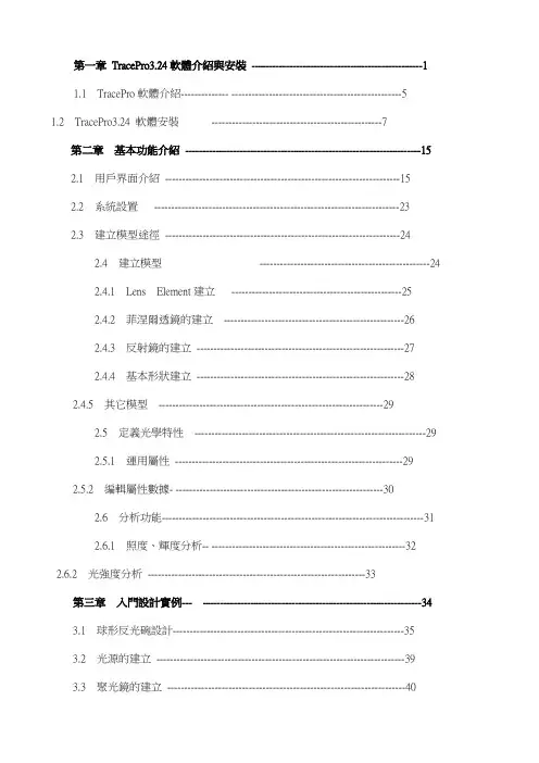
第一章TracePro3.24軟體介紹與安裝--------------------------------------------------11.1 TracePro軟體介紹-------------- --------------------------------------------------51.2 TracePro3.24 軟體安裝--------------------------------------------------7第二章基本功能介紹---------------------------------------------------------------------152.1 用戶界面介紹---------------------------------------------------------------------152.2 系統設置------------------------------------------------------------------------232.3 建立模型途徑---------------------------------------------------------------------242.4 建立模型--------------------------------------------------242.4.1 Lens Element建立--------------------------------------------------252.4.2 菲涅爾透鏡的建立-----------------------------------------------------262.4.3 反射鏡的建立-------------------------------------------------------------272.4.4 基本形狀建立-------------------------------------------------------------282.4.5 其它模型------------------------------------------------------------------292.5 定義光學特性--------------------------------------------------------------------292.5.1 運用屬性-------------------------------------------------------------------292.5.2 編輯屬性數據- -------------------------------------------------------------302.6 分析功能-----------------------------------------------------------------------------312.6.1 照度、輝度分析-- ---------------------------------------------------------322.6.2 光強度分析----------------------------------------------------------------33第三章入門設計實例--- ----------------------------------------------------------------343.1 球形反光碗設計--------------------------------------------------------------------353.2 光源的建立-------------------------------------------------------------------------393.3 聚光鏡的建立----------------------------------------------------------------------403.4 菲涅爾透鏡的建立-----------------------------------------------------------------423.4.1焦距為120mm的菲涅爾透鏡的建立-----------------------------------433.4.2焦距為185mm的菲涅爾透鏡的建立-------------------------------------463.5 液晶屏的建立-----------------------------------------------------------------------483.6 投影鏡頭的建立--------------------------------------------------------------------503.7 LCD投影機光學系統的建立---------------------------------------------------56第四章進階設計實例----------------------------------------------------------------------624.1 導光管設計-------------------------------------------------------------------------624.2 背光源設計-------------------------------------------------------------------------794.2.1背光源技術介紹--------------------------------------------------------------794.2.2設計背光源--------------------------------------------------------------------90第一章︰TracePro軟體介紹與安裝1.1 TracePro軟體介紹TracePro 是一套能進行常規光學分析、設計照明系統、分析輻射度和亮度的軟體。

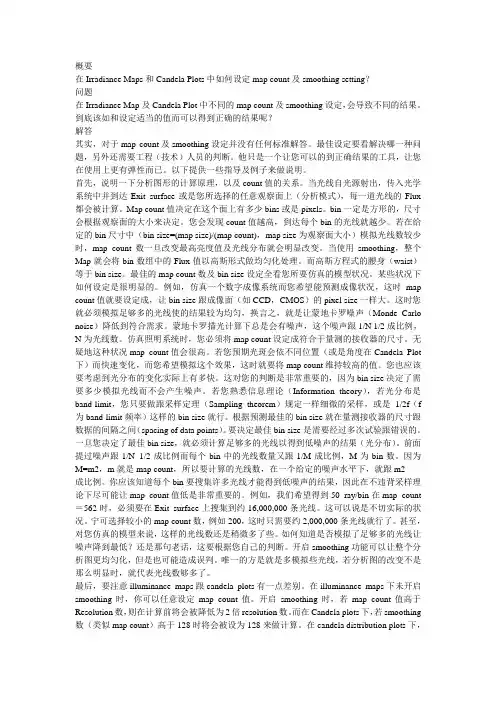
概要在Irradiance Maps和Candela Plots中如何设定map count及smoothing setting?问题在Irradiance Map及Candela Plot中不同的map count及smoothing设定,会导致不同的结果。
到底该如和设定适当的值而可以得到正确的结果呢?解答其实,对于map count及smoothing设定并没有任何标准解答。
最佳设定要看解决哪一种问题,另外还需要工程(技术)人员的判断。
他只是一个让您可以的到正确结果的工具,让您在使用上更有弹性而已。
以下提供一些指导及例子来做说明。
首先,说明一下分析图形的计算原理,以及count值的关系。
当光线自光源射出,传入光学系统中并到达Exit surface或是您所选择的任意观察面上(分析模式),每一道光线的Flux 都会被计算。
Map count值决定在这个面上有多少bins或是pixels。
bin一定是方形的,尺寸会根据观察面的大小来决定。
您会发现count值越高,到达每个bin的光线就越少。
若在给定的bin尺寸中(bin size=(map size)/(map count),map size为观察面大小)模拟光线数较少时,map count数一旦改变最高亮度值及光线分布就会明显改变。
当使用smoothing,整个Map就会将bin数组中的Flux值以高斯形式做均匀化处理。
而高斯方程式的腰身(waist)等于bin size。
最佳的map count数及bin size设定全看您所要仿真的模型状况。
某些状况下如何设定是很明显的。
例如,仿真一个数字成像系统而您希望能预测成像状况,这时map count值就要设定成,让bin size跟成像面(如CCD,CMOS)的pixel size一样大。
这时您就必须模拟足够多的光线使的结果较为均匀,换言之,就是让蒙地卡罗噪声(Monde Carlo noise)降低到符合需求。
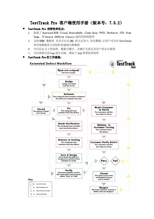
TestTrack Pro 客户端使用手册(版本号:7.5.2)●TestTrack Pro 的特性和优点:1.集成了Surround SCM, Visual SourceSafe, Clear Case, PVCS, Perforce, CVS, StarTeam, 和Source OffSite Classic源代码控制软件2.支持ODBC 数据库并且可以以XML 的方式导入/导出数据,让用户可以在TestTrack和其他数据库之间轻松快速地交换数据3.可以自定义工作流程,数据关键字,关键字关系以及用户的安全级别4.可以将相关的bug进行关联,增加了bug管理的系统性●TestTrack Pro的工作流程:●TestTrack Pro 客户端的安装:步骤:1) 双击TestTrack Pro 的安装程序“ttprowinclientinstall.exe”;2) 在安装页面中选择“NEXT”;选中接受协议,选择“NEXT”;3) 在选择安装类型的页面里面选择需要安装的类型,选择单独安装Windows客户端。
5)点击“NEXT”,进入下一步。
6) 进入Test Track 的安装路径选择页面,设置软件的安装路径,点击“NEXT”。
7) 安装完成,点击“Finish”按钮,结束安装。
如果是第一次安装,安装完成系统会提示需要重新启动计算机。
●TestTrack Pro 客户端登陆:1) 运行本机的TestTrack Pro Client 程序“TestTrack Pro Client”。
选择“开始”->“程序”->“Seapine Software”->“TestTrack Pro”->“TestTrack Pro Client”。
2) 第一次登陆时,TestTrack Pro Client 系统中没有服务器名称,系统会弹出框,需要用户输入TestTrack服务器的IP地址和端口号:在以上的窗口中,输入服务器名称:TestServer(也可自己另外命名)服务器地址:服务器端口号:选择“OK”保存设置3) 弹出登陆框,Server: 用户选择服务器(默认为刚才设置的服务器),用户可以点击“Setup”按钮来修改和重新选择服务器,输入服务的名称和服务所在的服务器IP 地址,如果输入的IP 地址的服务器开放了TestTrack Pro 的服务并且监听端口设置正确,该服务的数据库将被自动读取到以下界面。
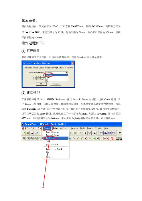
基本参数:型面为抛物面,聚光面积为72m 2,开口直径D=9577mm ,焦距f=7500mm 。
抛物面方程为 Z Y X 3022=+,聚光器共分为12块,每块间距为20mm 。
中心开口半径为100mm 。
接收平面半径为100mm 。
操作过程如下:(1) 打开软件双击快捷方式打开软件,出现如下的对话框,选择Standard 即可满足要求。
(2) 建立模型在菜单栏中选择Insert Reflector ,弹出Insert Reflector 对话框,选择Conic 选项,其中Shape 共分四种:球面、抛物面、椭圆面和双曲面。
在本例中聚光器型面为抛物面,所以选择Parabolic 。
此外其它的一些设置可以按上面的基本参数的要求填写,如下面对话框所示,填写完毕后点击Insert 按钮。
这样就建立了一个厚度为2mm 、焦距为7500mm 、开口直径为9577mm 、中间孔洞半径为100mm 、中心坐标为(0,0,0)的抛物面聚光器,如下右图所示。
要想从不同角度观察模型,可以从通过以下菜单进行操作。
其中和按钮比较常用,为全局放大,为对模型进行旋转观测。
要想观测模型的不同效果可以点击菜单栏View选项,有Silhouettes、Render、Wireframe、Hidden Line四个选项可供选择。
(3)分割聚光器按要求聚光器共分为12块,每块间距为20mm。
此处应用布尔运算对聚光器进行分割。
首先创建X向尺寸为10000mm(要比聚光器的开口直径大一些),Y向尺寸为20mm(为每块聚光镜的间距尺寸),Z向尺寸为5000mm(要比聚光器开口深度略大)的薄板,具体参数设置如下对话框所示。
薄板创建完成后,点击鼠标右键,出现下拉菜单,选择Rotate选项,对应弹出Rotation Selection 对话框,按对话框中参数填写完成按Copy按钮。
此操作共进行5次。
最终完成结果图如下所示。
Ctrl键加鼠标左键依次选择抛物镜面和各个薄板,点击鼠标右键,选择Subtract选项,对其进行布尔减运算。


光学系统设计物理系王宇兴TracePro 主要内容光源的建立方法各种参数的设定分析功能的使用档案转换模拟步骤准确模拟分析功能提高运算速度应用实例光学计算软件的计算方法Ray TracingSequential Ray TracingOSLO, Zemax, CodeV…Non-Sequential Ray TracingTracePro, ASAP, LightTools…BPM (Beam Propagation Method), FDTD 光波导,DWDM等BPM_CAD, WDM_Phasar…光学计算软件的计算方法Sequential Ray Tracing(序列光线追迹) OSLO 属于序列描光以光学面建立模型单一光源或者对多光源的设置受到局限需要设计者指定光学面的计算顺序各个光学表面仅计算一次(反射、折射、散射) 计算速度快可以进行优化和公差分析主要应用成像设计、透镜,镜头设计光学计算软件的计算方法Non-Sequential Ray Tracing(非序列光线追迹) TracePro 属于非序列描光以实体对象构建光路系统光线与实体表面的作用顺序不需设计者指定光线与实体表面的作用可以同时计算反射、折射、散射、吸收、衍射等行为需要足够多的光线数量以更接近真实的情况计算速度比较慢不易做自动优化和公差分析主要应用照明设计、杂散光分析TracePro 软件简介美国Lambda Research公司产品一套符合工业标准的ACIS固体模型绘图软件做发展的光机软件;广泛引用于镜头杂散光分析,背光板设计,LED 照明,灯具设计,车灯,投影显示器,扫描仪,医疗仪器等领域TracePro 软件简介目前版本4.0包含主程序以及与其它CAD软件的档案转换工具 主程序包含RC,LC,Standard,Expert四个版本可以对真实场景(Photo realistic)进行计算和显示具有众多的国内外用户群系统安装系统要求CPU:Pentium4 2.0GHz系统:Windows2000/XP/Vista内存:512MB(2GB)虚拟内存:2GB硬盘空间:450MB显卡:分辨率1208*1024显存:64MB以上,支持OpenGL初始设定对计算机内存、虚拟内存的要求较高 增加物理内存和虚拟内存的数量在进度大量光线计算时不要运行其它软件初始设定菜单ÆHelp ÆAbout 查看TracePro版本 ACIS Version第一套使用ACIS核心的软件可以顺畅的与其它造型软件进行文件的相互转换菜单ÆHelp ÆLinsense查看软件授权情况初始设定打开安装目录下面的EllipticalReflector.oml文件 在主界面中从不同角度观察模型,Zoom 使用各种渲染方式显示模型Render Wireframe11初始设定数据库设定TracePro 中表面(镀膜、散射、网点等)、实体(材 质、偏振、荧光等)特性都被存在统一的数据库中。

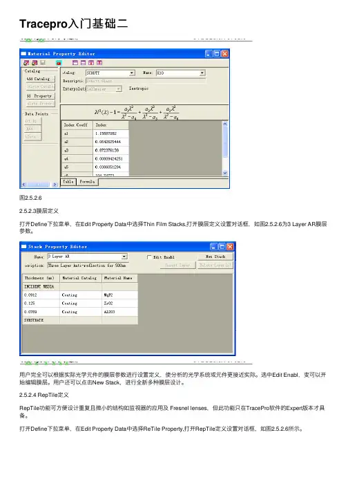
Tracepro⼊门基础⼆图2.5.2.62.5.2.3膜层定义打开Define下拉菜单,在Edit Property Data中选择Thin Film Stacks,打开膜层定义设置对话框,如图2.5.2.6为3 Layer AR膜层参数。
⽤户完全可以根据实际光学元件的膜层参数进⾏设置定义,使分析的光学系统或元件更接近实际。
选中Edit Enabl,变可以开始编辑膜层。
⽤户还可以点击New Stack,进⾏全新多种膜层设计。
2.5.2.4 RepTile定义RepTile功能可⽅便设计重复且微⼩的结构如监视器的应⽤及 Fresnel lenses,但此功能只在TracePro软件的Expert版本才具备。
打开Define下拉菜单,在Edit Property Data中选择ReTile Property,打开RepTile定义设置对话框,如图2.5.2.6所⽰。
在以后的章节中,本书将⽤⼤量的篇幅进⾏讲解,这⾥不做多的介绍。
2.6分析功能进⾏描光分析前,需要对描光进⾏设定,TracePro有两种模式可供选择:■分析模式(Analysis mode):计算光线在所有物体,表⾯上的位置,⽅向,Flux,偏振等值,并存储在硬盘。
这种分析模式速度慢,对PC硬件需求较⼤。
■仿真模式(Simulation mode):这种模式需要选取⼀个表⾯,TracePro 只存储这个⾯的光线资料。
速度⽐较快,对PC硬件要求不⼤。
TracePro具备强⼤的分析功能,主要分析功能如下:■照度、辉度、CIE⾊坐标、⾊度分析(Irradiance map)■光强度分析(Candela plot)■光线资料(光线位置、⽅向、通量)(Ray Histories)■选择需要分析的光线(Ray sorting)■⼈眼视觉模拟(Photorealistic Render)2.6.1照度、辉度分析照度、辉度分析在tracepro进⾏光学系统分析中常常使⽤到的功能如图2.6.1为⼀光学元件⼀⾯上的照度分析图。
Using templatesTemplates are intended to help simplify and speed up theprocess of entering and changing room information. They arebased on the idea that several pieces of information are commonfor many, if not all, of the rooms or types of rooms in a building.Examples of this type of similar information include designthermostat setpoints, wall/roof/floor construction types, amountand type of lighting, and so on. Templates are similar to theconcept of Master Cards in TRACE/Load Design600.The templates were designed for use in conjunction with theCreate Rooms – Single Sheet tab to allow the user to enterroom information on one screen. This allows much quicker entryof room data. In addition, because the user does not need torepeatedly select construction types, densities, and so on,templates reduce the chances of input errors. Finally, templatesalso make changes to files, and comparisons betweenalternatives, much easier.There are five types of templates. However, the Room templateacts as a super template. It does not contain any specific roomdata, but it allows grouping of the other four templates listedbelow:■Internal Load template■Airflow template■Thermostat template■Construction templateTemplates are generally created for each type of room in abuilding—office areas, conference rooms, hallways, rest rooms,and so on. After the templates have been set up, they areapplied, as appropriate, to the individual rooms in the CreateRooms section. The templates will bring in values that would betypical for the room type being entered in Create Rooms, andallow the user to override these inputs with any atypical valuesfor that specific room.In the following scenario, a set of templates for the office areas of a building will be created and applied in Create Rooms.1The first step in using templates is to create the templates. Click Create T emplates —TRACE 700 will open to the Room template.Note: It is much easier to create templates before the rooms have been input. Applying templates after the rooms have been input is time consuming and often difficult to do. Refer to Additional Items in this section for instructions on reverting inputs to templated values.2No templates have been input into this file.Therefore, the Internal Load tab should be selected.3From the Internal Load tab, the generalcharacteristics of theoffice areas’ internal loads will be input. Click New and enter Office Areas into the Description field. Enter the appropriate T ype , Density , Loads , and Schedule for the people. Repeat this for Lighting andMiscellaneous loads .Note: The internal load schedules typically should not use the schedule Available 100% or any schedule where the heating-design day type is greater than zero. This will cause TRACE 700 to take credit for internal loads during the heating-designcalculation. For additional details on schedules, refer to “Creating schedules” on page 6–120.4With the generalcharacteristics for theoffice areas’ internal loads defined, select theAirflow tab. Here, thegeneral characteristics ofthe office areas’ airflowswill be input. Click Newand enter Office Areasinto the Description field.Input the appropriateT ype, airflow rate (if thedefault value needs to beadjusted), and Schedulefor the Ventilation.Repeat this for all relevant fields on the Airflowtemplate.5With the generalcharacteristics for theoffice areas’ airflowsdefined, select theThermostat tab. In thisscenario, all of the roomsin the building will beconditioned to the samethermostat setpoints,allowing a singleThermostat template tobe used for the entirebuilding. Click New andenter Building in theDescription field. Inputthe Cooling dry-bulbsetpoint, Heating dry-bulb setpoint, andRelative humidity. If thefile will be used for energy analysis, then the Cooling driftpoint and Heatingdriftpoint, or the Coolingthermostat schedule andHeating thermostatschedule, should be input as well.Note: In almost all cases, theAuxiliary supply and VAVminimum schedule should beleft at their default values. Also, the airflow schedules must not be internal load schedules orany schedule where theheating-design day type is zero.This will cause TRACE700 toneglect airflow loads during the heating-design calculation. For additional details on schedules, refer to “Creating schedules”on page 6–120.Note: Typically users need to either create their own Thermostat schedules orselect none and let theprogram use the driftpoints (Thermostat schedulesoverride the driftpoints and setpoints for energy analysis calculations). Also, the thermostat driftpoints activate whenever there are 5percent or less of the people in the space (determined from the people schedule on a room-by- room basis).6With the generalcharacteristics for thebuilding thermostatsetpoints defined, clickthe Construction tab. In this scenario, theenvelope components of the building will beconstant throughout thebuilding. Therefore, asingle Constructiontemplate can be used forthe entire building. ClickNew and enter Buildinginto the Description field.Next, select theappropriate Constructiontypes for the building,override U-factors andShading coefficients ifnecessary, and input theWall, floor-to- floor, andPlenum heights. If thebuilding does not containa certain constructiontype, use the defaultvalue. In this scenario, the building has noskylights—therefore, thedefault construction value will be used in thetemplate.7Finally, select the Room template so that theindividual templates canbe grouped together. Click New and enter OfficeAreas in the descriptionfield. Next, select theappropriate Internal Load, Airflow, Thermostat, and Construction templatesfor the room type.Note: Typically the wall height and floor-to-floor height will be the same value. Refer to onlineHelp for additional details.8Click Close T emplates and click Create Rooms.To start inputting theroom data, give the rooma name (Office 101, in thiscase). For the Roomtemplate, select OfficeAreas.9The user now needs to input the appropriateroom-specific data (sizeof the space, walls,windows, roofs,partitions, and floors) and override any data fromthe templates that is notappropriate for the space.In this scenario, the roof,wall, glass, and floor area need to be input. TheSingle Sheet tab, pairedwith the data from thetemplates, can be used to input all of this data.Because this is the firstroom to be defined withthe templates, it is usually recommended that theindividual tabs be checked to verify the inputs for the space.10Now that Office 101 has been created, the otheroffices in the building can be modeled using thesame set of templates.Remember, templates for each type of room(offices, hallways,restrooms, and so forth)should be created, rather than one set of templates per room entered inCreate Rooms .In a typical TRACE700 file, templates for the other types of rooms (conference rooms, hallways, and so on) in the building would now be created.In this scenario, only offices will be modeled. A sample room will be input to show how to apply the templates. The room is 1,500ft2, has a flat roof, one east-facing exterior wall with 30percent glass, and is fairly typical of the other office spaces.Note: When the Roomtemplate is selected, manyof the values (such asInternal loads and Airflows)will populate based on theinputs from the InternalLoad, Airflow,Thermostat, andConstruction templates.Note: This building does not haveany skylights. Therefore, none willbe input in the Create Roomssection. This is the reason that theskylight glass type on theConstruction template could beleft at the default value.Additional items and notes1Any changes made to the template(s) will change the data in all of the rooms that use that template. Therefore, if the glass type specified in the project changes, all that the user needs to do is change the glass type in the Construction template(s) used by the rooms. If no templates were used in the file, then each wall would need to be manually changed to the new glass type. This is one of the ways that templates help save time.2When a templated value is overridden in Create Rooms, the color of the entry changes from red to black. It is important to understand this distinction. When you reapply or change anexisting template, only the values in red are affected. Entries in black must be changed manually or reverted back to thetemplated value.3To go back to an original template value, click *T emplate on the list for that parameter, or type in * and press enter for thenumeric fields.4Do not use any non-alphanumeric characters in the names of templates or rooms.5Create templates before creating rooms.6Project templates apply to only one file.7Global templates can be used in any number of files. They are created from the Library/Template Editors program. Globaltemplates are created in a very similar process and are usedwhen the same type of buildings will be modeled repeatedly.8 A Project template cannot be exported to a Global Template.9Create a Global template to make it available for any file, then add the Global Room (or individual) template into the Project.10When editing information, always check the upper left-hand corner of the screen to ensure that the correct alternative isbeing edited. Also verify that the correct template is being edited.11For additional details on how to use alternatives and templates, please refer to “Creating alternatives” on page6–114.12In Component T re e view, the user can press ALT+Z to revert the selected overridden value to a templated value quickly.Creating alternativesAlternatives can be created efficiently using three options:Use/Copy, Create based on, and Create new.■Use/Copy: Simulation will use data from another alternative,which minimizes calculation time and will not increase file size.Note: The Use/Copy option should only be applied to sections ofthe alternative where no changes will be made, because the userwill not be able to edit information in any section that uses datafrom another alternative.■Create based on: TRACE700 will create an editable copy ofinformation from another alternative, which will increase the filesize and the calculation time. However, the user can editinformation in any section that is created based on data from aprevious alternative. This option should be used when changesneed to be made to a section, but inputs similar to a previousalternative will be used.■Create new: TRACE700 will create a new section with no data, which will increase the file size and increase calculation time. Theuser can input completely new information in any section that isnew. This option should be used when changes need to be madeto a section or alternative, but inputs are not similar to the otheralternatives.Application considerations■The first step in creating alternatives is to determine how similar the existing alternative and the new alternative will be. In general,the more sections that use data from another alternative, thebetter. However, if changes need to be made to a portion of analternative, Create based on (if the alternatives are similar) orCreate new (if the alternatives are very dissimilar) should beused for the appropriate section(s). Two examples will be used toillustrate how to create alternatives in TRACE700:Multiple air-handlers served by a chiller plant vs. a large centralair-handler served by the same chiller plant,andA glass comparison.。
TracePro介绍TracePro基本信息TracePro是一套普遍用于照明系统、光学分析、辐射度分析及光度分析的光线模拟软件。
它是第一套以ACIS solid modeling kernel 为基本的光学软件。
第一套结合真实固体模型、强大光学分析功能、资料转换能力强及易上手的使用界面的模拟软件。
TracePro可利用在显示器产业上,它能模仿所有类型的显示系统,从背光系统,到前光、光管、光纤、显示面板和LCD投影系统。
优点比起传统的原形方法,TracePro在建立显示系统的原型时,在时间上和成本上要降低30-50%。
常建立的模型照明系统、灯具及固定照明、汽车照明系统(前头灯、尾灯、内部及仪表照明)、望远镜、照相机系统、红外线成像系统、遥感系统、光谱仪、导光管、积光球、投影系统、背光板。
功能TracePro作为下一代偏离光线分析软件,需要对光线进行有效和准确地分析。
为了达到这些目标,TracePro具备以下这些功能:处理复杂几何的能力,以定义和跟踪数百万条光线;图形显示、可视化操作以及提供3D实体模型的数据库;导入和导出主流CAD软件和镜头设计软件的数据格式。
使用在使用上,TracePro使用十分简单,即使是新手也可以很快学会。
TracePro使用上只要分5步:1、建立几何模型;2、设置光学材质;3、定义光源参数;4、进行光线追迹;5、分析模拟结果。
2应用范围编辑1. LED光源和LED照明.2. 日光灯、灯盘和栅格.3. 建筑和展示照明.4. 消费产品.5. 车灯和航空照明.6. 医疗设备和舞台照明.7. 运输和应急照明.。
Tracepro 入门与进阶CYQ DESIGN STUDIO1Tracepro 入门与进阶CYQ DESIGN STUDIO内 容 简 介本书以美国 Lambda Research Corporation 的最新 3.24 版本为蓝本进行编写, 内容涵盖了 tracepro3.24 光学仿真设计的概念、tracepro 软件的配置和用户定制、光 学元件模型的创建、描光、分析等内容。
本书章节的安排次序采用由浅入深,前后呼应的教学原则,在内容安排上,为方 便读者更快、更深入地理解 tracepro 软件中的一些相关概念、命令和功能,并对运用 该软件进行光学仿真设计的过程有一个全局的了解,本书中介绍了单片 LCD 投影机 的仿真设计全过程,同时在本书的最后一章详细介绍了背光源等光学仿真设计过程, 增强了本书的可读性和实用性,摆脱单个概念、命令、功能的枯燥讲解和介绍。
本书可作为光学专业人员的自学教程和参考书籍, 也可作为大专院校光学、 光电专业 的学生学习 tracepro 的使用教材。
2Tracepro 入门与进阶CYQ DESIGN STUDIO前言Tracepro 是一套可以做照明光学系统分析、传统光学分析,辐射度以及光度分析 的软件, 它也是第一套由符合工业标准的 ACIS 立体模型绘图软件发展出来的光机软 件。
功能强大的 Tracepro 减轻了光学设计人员的劳动强度,节约了大量的人力资源, 缩短了设计周期,还可以开发出更多质量更高的光学产品。
但目前 Tracepro 学习教 程甚少, 不少初学者苦于无参考学习资料而举步为艰。
本人根据从事光学设计的经验 与运用 Tracepro 的体会,汇集成书,目的是使 Tracepro 的初学人员能快速入门,快 速见效,使已入门者能进一步提高 Tracepro 的应用水平和操作能力,从而在工作中 发挥更大的效益,为中国的光学事业作出贡献! 本书乃仓促而成,虽然几经校对,但错误之处在所难免,恳请广大读者朋友予以 指正,不甚感谢! 电子邮箱: cyqdesign@陈涌泉 2004 年 12 月 4 日3Tracepro 入门与进阶CYQ DESIGN STUDIO目录第一章 TracePro3.24 软件介绍与安装 --------------------------------------------------1 1.1 TracePro 软件介绍-------------- --------------------------------------------------5 1.2 TracePro3.24 软件安装 --------------------------------------------------7 第二章 基本功能介绍 ---------------------------------------------------------------------15 2.1 用户界面介绍 ---------------------------------------------------------------------15 2.2 系统设置 ------------------------------------------------------------------------23 2.3 建立模型途径 ---------------------------------------------------------------------24 2.4 建立模型 --------------------------------------------------24 2.4.1 Lens Element 建立 --------------------------------------------------25 2.4.2 菲涅尔透镜的建立 -----------------------------------------------------26 2.4.3 反射镜的建立 -------------------------------------------------------------27 2.4.4 基本形状建立 -------------------------------------------------------------28 2.4.5 其它模型 ------------------------------------------------------------------29 2.5 定义光学特性 --------------------------------------------------------------------29 2.5.1 运用属性 -------------------------------------------------------------------29 2.5.2 编辑属性数据- -------------------------------------------------------------30 2.6 分析功能-----------------------------------------------------------------------------31 2.6.1 照度、辉度分析-- ---------------------------------------------------------32 2.6.2 光强度分析 ----------------------------------------------------------------33 第三章 入门设计实例--- ----------------------------------------------------------------34 3.1 球形反光碗设计--------------------------------------------------------------------35 3.2 光源的建立 -------------------------------------------------------------------------39 3.3 聚光镜的建立 ----------------------------------------------------------------------40 3.4 菲涅尔透镜的建立-----------------------------------------------------------------42 3.4.1 焦距为 120mm 的菲涅尔透镜的建立 -----------------------------------43 3.4.2 焦距为 185mm 的菲涅尔透镜的建立-------------------------------------46 3.5 液晶屏的建立-----------------------------------------------------------------------48 3.6 投影镜头的建立--------------------------------------------------------------------50 3.7 LCD 投影机光学系统的建立 ---------------------------------------------------56 第四章 进阶设计实例----------------------------------------------------------------------62 4.1 导光管设计 -------------------------------------------------------------------------62 4.2 背光源设计 -------------------------------------------------------------------------69 4.2.1 背光源技术介绍--------------------------------------------------------------69 4.2.2 设计背光源--------------------------------------------------------------------734Tracepro 入门与进阶CYQ DESIGN STUDIO第一章:TracePro 软件介绍与安装1.1 TracePro软件介绍TracePro 是一套能进行常规光学分析、设计照明系统、分 析辐射度和亮度的软件。
6–39CDS-PRM001-EN • TRACE 700 User’s Manual Advanced Usage and General Modeling Tips No- or low-heating energy consumption No- or low-heating energy consumptionThere are several reasons why an energy simulation cancalculate no/low amounts of heating energy despite showing realistic heating loads in the design calculation. The following points are common reasons why heating energy is often underestimated.Note: Not all of these inputs are necessarily incorrect. Some are reasons that heating energy may be minimized or eliminated.Example 11The default values for the thermostat driftpoints, 90°F and 55°F respectively, are being used. This means that whenever there are 5percent or less of the people in the space (determined from the people schedule), the room will be allowed to drift up to 90°F or down to 55°F before the equipment turns back on. If the building control system is not going to allow the room setpoints to setback this far, or at all, the default values need to be set to more realistic values.2The selected Thermostat schedules allow the building to drift to an unrealistic temperature at night. For example, the CSTAT and HSTAT schedules will allow the building to drift up to 95°F and down to 55°F , depending on the time of day. The values used in the schedules can be viewed by clicking Schedules on the Libraries menu and selecting Thermostat as the schedule type. Typically, users need to either create their own Thermostat schedules, or select none and let theprogram use the driftpoints (the schedules override the driftpoints).Not correcting this input will result in an underestimation of the coolingand heating energy at night. Refer to “Frequently asked questions” onpage6–20 for information regarding how driftpoints and thermostatschedules interact.3Large areas are being modeled as a single space. This can cause theinternal loads to negate the envelope losses, leading to anunderestimation or elimination of the heating loads in the energysimulation. Because internal loads are typically neglected during theheating design calculations, reasonable heating-design results may bereturned using this assumption. Modeling interior and perimeter areasas separate rooms will eliminate this modeling error. Refer to“Modeling large rooms and zones” on page6–45 for a detailedexplanation.Example 21The Cooling Only (Design) schedule is selected for any of the internalloads. This schedule should typically only be used for designcalculations, not for energy analysis. It simulates 100percent of theinternal loads in the building 24hours a day (except during the heating-design portion of the calculation), which may not be what is actuallyoccurring in the building. This tends to lead to the internal loadsmeeting the heating loads. To view the schedule, click Schedules onthe Libraries menu and select Utilization as the schedule type. Herethe user should be able to view the schedule and find schedules thatmore-closely follow the actual operation of the building.2The internal loads are scheduled as Available 100%. This scheduleshould not be used for internal loads. It simulates 100percent of theinternal loads in the building 24hours a day, which may not be what isactually occurring in the building. In addition, it also tells the program totake credit for the internal loads during the heating-design calculation.6–40Advanced Usage and General Modeling Tips TRACE 700 User’s Manual • CDS-PRM001-EN No- or low-heating energy consumption6–41CDS-PRM001-EN • TRACE 700 User’s Manual Advanced Usage and General Modeling TipsNo- or low-heating energy consumption This schedule tends to lead to an underestimation of heating energy and undersizing of the heating coils, due to the internal loads meeting all or most of the heating loads. To view the schedule, click Schedules on the Libraries menu. Here the user should be able to view the schedule and find schedules that more closely follow the actual operation of the building.3The custom schedule(s) for internal loads have values greater than zero for the heating-design day type. This tells the program to take credit for the internal loads during the heating-design calculation. This tends to lead to undersizing of the heating coils and is not common design practice. To view the schedule, click Schedules on theLibraries menu. Here the user should be able to view the schedule and the individual day types.Example 31No infiltration has been input on the Airflows tab of Create Rooms .Infiltration is air from outside the building that leaks into the room, often adding to the heating requirement.2No VAV minimum airflow has been input for VAV systems. This can result in no (or minimal) airflow being supplied to the space in heatingmode.6–42Advanced Usage and General Modeling TipsTRACE 700 User’s Manual • CDS-PRM001-ENNo- or low-heating energy consumption Example 41The heating supply-air temperature has been input at an unrealistically low temperature. The capacity of the heating coil is calculated based on the airflow through the coil and the temperature difference across the coil. If coil capacity is underestimated, the energy consumed by the coil will also be underestimated.Example 51The selected fan schedule does not allow the fan to run at hours when heating loads occur. If the fan is turned off, the heating coils cannot consume energy. Schedules for fans should be used only when the fans are turned off for certain time periods and not allowed to turn back on no matter what the temperature is in the space. The schedules Off (0percent) and Heating Only (Design) would be two6–43CDS-PRM001-EN • TRACE 700 User’s Manual Advanced Usage and General Modeling TipsNo- or low-heating energy consumption examples of incorrect schedule selection. Refer to “Frequently asked questions” on page 6–20 for additional details regarding how fan schedules and fan cycling operate in TRACE 700.Example 61The heating coil(s) capacity has been zeroed out. This will cause the program to eliminate all energy associated with the coil(s).2The heating coil(s) have been scheduled off during hours when heating loads occur. If the coil(s) are turned off, they cannot consume energy. Schedules for coils should be used only when the coils are turned off for certain time periods and not allowed to turn back on no matter what the temperature is in the space.Example 71The heating equipment schedule does not allow the heatingequipment to run during hours when heating loads occur. If the heatingequipment is turned off, then it cannot consume energy or meet thecalculated heating loads.Note: Switching to a full-year (8760 analysis) will typically provide a more-accurate estimation of heating energy consumption. Refer to “Addingweather locations and activating the 8760 calculation methodology” onpage6–137.6–44Advanced Usage and General Modeling Tips TRACE 700 User’s Manual • CDS-PRM001-EN No- or low-heating energy consumption。
Tracepro中⽂⼿册第六章第六章分析检验光线追迹结果完成光线追迹之后,当进⾏结果评估时,分析菜单提供多种⽅法来显⽰光线追迹数据。
Displaying Rays 和 Ray Sorting让你观察数据是否是你期待的结果。
Irradiance Maps, Ray Tables and Polarization Maps 提供每⼀个表⾯的模拟结果。
Candela Plots 显⽰模型中光线数据的⾓度分配。
Volume Flux Viewer能够观察模型内部的流量分布。
Reports Menu 帮助你完成分析光线数据和模型的多种报告形式。
Tools 菜单包括附加的功能来帮助你完成光线追迹结果。
Analysis Menu在本章中的描述中,⼤多数的光线追迹结果从Analysis Menu中得到,光线追迹也被包含在Analysis Menu项⽬的开始,这在第五章有详细地介绍。
Display RaysAnalysis | Display Rays 选项允许你控制光线的显⽰。
“Analysis Mode(分析模式)”下,在完成光线追迹后, 光线默认地被显⽰或取消。
光线在“Simulation Mode(模拟模式)”中不能够被显⽰。
要关闭显⽰的光线,只需进⼊Analysis | Display Rays,显⽰光线的状态是通过菜单上√ 标志来标注的。
如果被trace的光线有很多并且带有许多的splits or branches,程序会花很长时间来显⽰这些光线。
你可以根据需要设定Window|Auto Update来更新光线的显⽰,这时的光线不会被随时更新,直到你按“F5”或选择Window|Refresh。
光线也可能在和图画程序组合期间同步显⽰,当具有优先设置时。
参考2.43页的“Ray Display”。
你也可以按照下⾯的描述使⽤Ray Sorting来决定哪些光线显⽰。
Ray Colors可以通过Ray Color对话框来设置光线的颜⾊来取代预先设值的颜⾊值,对于单⾊光,Ray Color对话框提供三种预设的颜⾊值来显⽰光线颜⾊。