Flexural Behavior of FRP-Reinforced Concrete Composite Member
- 格式:pdf
- 大小:388.40 KB
- 文档页数:7

Influence of fiber type on concrete flexural toughnessJianguo Han 1, a , Peiyu Yan 2,b1 Department of Civil Engineering, Tsinghua University, Beijing, 100084, China2Department of Civil Engineering, Tsinghua University, Beijing, 100084, Chinaahanjg@, b yanpy@Keywords: Concrete, Fiber, Flexural Toughness, Strength, Curing Age.Abstract. Using PCER (post-crack energy ratio) method and plain concrete specimen as reference, the flexural toughness enhancing ability of propylene spinning fiber, propylene monofilament fiber and end-deformed steel fiber was studied. Experiment results show that under the common engineering dosage, the flexural toughness enhancing ability of end-deformed steel fiber is far more outstanding than propylene fibers, and comparing with each other, the flexural toughness enhancing ability of propylene spinning fiber is better than propylene monofilament fiber. As far as one type of fiber is concerned, under the same dosage, along with the enhancement of concrete strength grade, the flexural toughness enhancing ability tends to decrease. Meanwhile, along with enhancement of curing age, the flexural toughness enhancing ability tends to decrease also. IntroductionConcrete is a quasibrittle material, and adding fiber to concrete can enhance its toughness. About fiber type and dosage on the concrete flexural toughness enhancement ability, lots of researches have been done. Balaguru studied fiber type and volume fraction on flexural toughness, and the results show that the volume fraction should increase along with the increase of concrete strength grade to maintain concrete toughness, and fiber of hooked-end geometry works better than corrugated one [1]. Punyamurtula studied the working effect of polymer fiber, and the results show that concrete flexural toughness enhances along with the enhancement of fiber toughness and diameter [2]. Zhou studied the effect of steel fibber volume fraction on concrete toughness, and the results show that along with the increase of fiber volume fraction, the descending tendency of load-deflection curve after peak load becomes soft [3]. But the concrete flexural toughness evaluating method used were somewhat diverse, the methods used including ASTM C1018 specification [4], JSCE SF4 specification [5] and RILEM TC162 specification [6], and the results were lack of comparability since the evaluating method used was different.Based on the aforementioned flexural toughness evaluating methods, the author proposed a new flexural toughness evaluating method named PCER (post-crack energy ratio) method [7]. The PCER method can be used to evaluate the flexural toughness of fiber reinforced concrete and plain concrete as well. In this paper, the flexural toughness enhancing ability of two kinds of propylene fibers and one kind of steel fiber under their common engineering dosage were evaluated using PCER method. Specimen Preparation and Testing ArrangmentMaterials and Mix Proportion. The materials used include P.O 42.5 Portland cement, class F and grade I fly ash, silica fume with amorphous silica content more than 90%, river sand of the fineness modulus 2.8, limestone aggregate of the diameter 5-20mm, and polycarboxylate type water reducer. Concrete of the strength grade C40, C60 and C80 were made with the mix proportion given in Table 1. three kinds of fiber ,under their common engineering dosage were added to concrete to make fiber reinforced concrete, the property and dosage of fibers are given in Table 2.Advanced Materials Research Vols. 287-290 (2011) pp 1179-1183Online available since 2011/Jul/04 at © (2011) Trans Tech Publications, Switzerlanddoi:10.4028//AMR.287-290.1179Concrete specimens with the dimension 150×150×550mm were made. The workability of fresh concrete was adjusted by the dosage of water reducer to be 160mm slump. Fresh concrete was cast to steel mold and consolidated by vibration; concrete specimens were covered with a plastic sheet and cured under room temperature. After demoulding, concrete specimens were cured under standard condition, with T=20˚C and RT≥95%. Concrete flexural toughness was tested at the curing age of 7 and 28 days.Table 1 Concrete mix proportionNumber Cement (kg/m 3) Fly ash (kg/m 3) Silica fume (kg/m 3) Water (kg/m 3) W/B Sand (kg/m 3) Aggregate (kg/m 3) C40 306 102 0 175 0.43 749 1125 C60 375 125 0 150 0.30 720 1060 C8043595401540.276561070Table 2 Property and dosage of fibersNumber Name Diameter (mm) Length (mm) Elastic Moduls(GPa)Tension Strength (MPa) Dosage (kg/m 3) PPSF Propylene spinning fiber 1.0 38.0 ≥5.0 ≥450 7.0 PPMF Propylene monofilamentfiber 0.30 19.0 ≥3.5 ≥400 2.0 EDSFEnd-deformed steel fiber0.5435.0220>100030.0Testing and Evaluating Method. The testing and evaluating of flexural toughness of different fiber reinforced concrete was performed according to PCER method. The dimension of concrete specimen was 150×150×550mm. One day before test, concrete specimens of the due age were take out form the curing room to make a notchof 25mm depth and 3mm width, after that concrete specimen were restored to the curing room until the test. The test apparatus include a loop-control hydraulic machine and a linear variable differential transformer (LVDT) as deflection data collector. The support span of the specimen was 500mm and the deflection speed was 0.2mm/min. The illustration of test arrangement is given in Fig. 1.Fig. 1 Illustration of test arrangementBase on bilinear model, the ascendant branch of PCER method is from the beginning point to peak load, and the descending branch is from peak load to the set deflection point define by the value of K. PCER method evaluates concrete toughness by the area ratio of area under the descending branch of bilinear model to area under the real load-deflection curve after the peak load, as illustrated in Fig. 2 and Eq. 1. Since the area under the load-deflection curve is the energy dissipated during crack propagation, the area ratio is energy ratio in actually. The higher the PCER value calculated by Eq. 1, the higher the flexural toughness of the tested concrete possesses.L o a d (N )δF peakAB CDFig. 2 Illustration of PCER evaluating methodpeak postPCER E 0.5F k=. (1)In which, the PCER value is the energy ratio after the peak load; post E is the area under real load-deflection curve after peak load, defined as the region ABCE in Fig. 1 (N·mm); peak F is the peak load (N); K is the set value, and the recommend scope is 0.1-10mm. During the calculating process using Eq. 1, when the tested ultimate deflection value is lower than the set value of K, post E should be calculated using the real load-deflection curve after peak load until the ultimate deflection value. Results and AnalysisIn this paper, the K value in Eq. 1 is defined as 2.0mm. And based on the load-deflection curve of different fiber reinforced concrete specimens, the influence of fiber type on concrete flexural toughness, the influence of strength grade and curing age on fiber effect are analyzed.Influence of Fiber Type on Flexural Toughness. Fig. 3 manifests the influence of fiber type and concrete strength grade on flexural toughness, in which Fig. 3a shows the analysis results at the curing0.00.40.81.21.6P C ERStrength Grade(3a) 7 days0.00.40.81.2P C E RStrength Grade(3b) 28 daysFig. 3 Influence of fiber type on flexural toughnessNote: The symbol “Control” represents plain concrete, used as reference.From Fig. 3, it can be seen that comparing to the referencing plain concrete, all of the three fibers can enhance concrete flexural toughness, the enhancing ability of steel fiber is far more significant than the other two propylene fibers, and the enhancing tendency of different fiber keep the same regardless of concrete strength grade and curing age. Meanwhile, the flexural toughness enhancing ability of propylene spinning fiber is higher than that of propylene monofilament fiber by comparison.Influence of Strength Grade on Fiber Effect. Fig. 4 manifests the influence of concrete strength grade on fiber effect, in which Fig. 4a shows the analysis results at the curing age 7 days and 4b shows the analysis results at the curing age 28 days. As can be seen that along with the increase of concrete strength grade, the flexural toughness enhancing ability of all fibers decrease no matter of the curing age. Meanwhile, as can be seen also that along with the increase of concrete strength grade, the PCER value of plain concrete decrease, this means that plain concrete flexural toughness decreases alongP C E RFiber Type(4a) 7 days0.00.40.81.2P C E RFiber Type(4b) 28 daysFig. 4 Influence of strength grade on fiber effectInfluence of Curing Age on Fiber Effect. Fig. 5 manifests the influence of curing age on fiber effect, in which Fig. 5a, 5b and 5c shows the analysis results of C40, C60 and C80 concrete separately. As can be seen that along with the increase of curing age, the flexural toughness enhancing ability of all fibers decrease no matter of concrete strength grade. Meanwhile, as can be seen also that along with the increase of curing age, the flexural toughness of plain concrete decreases, this means plain concrete getting brittle along with the increase of curing age.(5a) C40(5b) C60(5c) C80Fig. 5 Influence of curing age on fiber effectConclusionIn this paper, PCER method was adopt to analyze the flexural toughness enhancing ability of three kinds of fiber, under the influence of concrete strength grade and curing age. The following conclusion can be drawn.(1) Comparing to the other two propylene fibers, end-deformed steel fiber has far more higher flexural toughness enhancing ability. Meanwhile, comparing with each other, the flexural toughness enhancing ability of propylene spinning fiber is better than propylene monofilament fiber.(2) For any of the three kinds of fiber, under the same dosage, the flexural toughness enhancing ability decrease along with the increase of concrete strength grade.(3) Along with the increase of curing age, the flexural toughness enhancing ability decrease for all of the three fibers.(4) The flexural toughness of plain concrete decrease along with the increase of strength grade and curing age.AcknowledgmentThis work is supported by the National Science and Technology Supporting Plan of China under grant 2008BAE61B05.References[1] P. Balaguru, R. Narahari, M. Patel: ACI Materials Journal Vol. 89 (1992), p. 541[2] V. K. Punyamurtula, Y. Qiao: International Journal of Damage Mechanics Vol. 17 (2008), p. 363[3] H. T. Zhu, Y. D. Gao, L. Xie and Q. M. Zhang: Journal of The Chinese Ceramic Society Vol. 32(2004), p.656 (In Chinese)[4] ASTM C1018-97 Standard test method for flexural toughness and first-crack strength of fiberreinforced concrete (Using beam with third-point loading) [S][5] JSCE Standard SF4, Method of test for flexural strength and flexural toughness of fiberreinforced concrete[S]. (1984), p.58[6] RILEM TC 162-TDF, Test and design methods of steel fiber reinforced concrete, BENDINGTEST. Materials and Structures Vol. 35 (2002), p.579[7] J. G. Han, P. Y. Yan: China Concrete. (2010), p. 42 (In Chinese)Applications of Engineering Materials10.4028//AMR.287-290Influence of Fiber Type on Concrete Flexural Toughness10.4028//AMR.287-290.1179DOI References[2] V. K. Punyamurtula, Y. Qiao: International Journal of Damage Mechanics Vol. 17 (2008), p.363. /10.1177/1056789508092398。

中文2630字AN EXPERIMENTAL STUDY ON FLEXURAL BEHAVIOR OF RC BEAMS STRENGTHENED WITH NSM REINFORCEMENTWoo-Tai JUNG1, Young-Hwan PARK2, Jong-SupABSTRACT: This study presents the results of experiments performed on RC (Reinforced Concrete) beams strengthened with NSM(Near Surface Mounted) reinforcement. A total of 6 specimens have been tested. The specimens can be classified into EBR(Externally Bonded Reinforcement) specimen and NSM reinforcements specimens. Two NSM specimens with space variables were strengthened with 2 CFRP(Carbon Fiber Reinforced Polymer) strips. Experimental results revealed that NSMspecimens used CFRP reinforcements moreefficiently than the EBR specimens. Even if CFRP crosssection areas of NSM specimens have 30%,50% of EBR Specimen, the strengthening effect of NSMspecimens is superior to EBR specimen. NSM specimens with space variables showed that thstrengthening effect of the specimen with narrow space is slightly increased as compared to thespecimen with wide spaceu KEYWORDS: carbon fiber reinforced polymer, externally bonded CFRP reinforcements, nearsurface mounted CFRP reinforcements, strengthening1. INTRODUCTIONAmong the various strengthening techniques that have been developed and applied to strengthendeteriorated RC structures, a number of applications using FRP reinforcements have significantly increased recently. FRP reinforcements are bonded to concrete surfaces by adhesives but frequently experience debonding failure at the interface between FRP reinforcements and concrete. Most research, to date, has focused on investigating the strengthening effects and failure modes of EBR systemThe problem of premature failure of EBR system may be solved by increasing the interface between FRP and concrete. Using this principle, the NSM system has been introduced recently. The NSM system for concrete structure using steel reinforcement already began in 1940s. However, the corrosion of the steel reinforcement and the poor bonding performance of the grouting material largely impaired its application. The development of improved epoxy and the adoption of FRP reinforcement offered the opportunity to implement NSM system (Hassan and Rizkalla 2003; Täljsten and Carolin 2001). Because of their light weight, ease of installation, minimal labor costs and site constraints, high strength-to-weight ratios, and durability, FRP repair systems can provide an economically viable alternative to traditional repair systems and materials(Mirmiran et al. 2004). Rizkalla and Hassan (2002) have compared EBR and NSM system in terms of cost, including costs of materials and labor,and strengthening effect. They concluded that the NSM system was more cost-effective than the EBR system using CFRP strips.This experimental study investigates the applicability and strengthening performances of NSM using CFRP strips. For comparison, flexural tests on RC beams strengthened by EBR and by NSM have been performed. In addition, specimens with space variables have been tested to compare the strengthening performance by cross section with wide and narrow space.2. EXPERIMENTAL PROGRAM2.1 MANUFACTURE OF SPECIMENSA total of 6 specimens of simply supported RC beams with span of 3m have been cast. The details andcross-section of the specimens are illustrated in Figure 1. A concrete with compressive strength of31.3 MPa at 28 days has been used. Steel reinforcements D10(φ9.53mm) of SD40 have been arrangedwith steel ratio of 0.0041 and a layer of three D13(φ12.7mm) has been arranged as compressionreinforcements. Shear reinforcements of D10 have been located every 10 cm in the shear zone to avoidshear failure. Table 1 summarizes the material properties used for the test beams.2.2 EXPERIMENTAL PARAMETERSTable 2 lists the experimental parameters. The control specimen, an unstrengthened specimen, has been cast to compare the strengthening performances of the various systems. CPL-50-BOND, EBR specimen, has been strengthened with CFRP strip. The remaining 4 specimens were strengthened with NSM CFRP strips. Among the specimens strengthened with NSM reinforcements, an embedding64 depth of NSM-PL-15 and NSM-PL-25 is 15mm and 25mm, respectively. A space between grooves of NSM-PL-25*2 and NSM-PL-2S is 60mm and 120mm, respectively. The strengthened length of all thespecimens has been fixed to 2,700 mm2.3 INSTALLATION OF THE FRP REINFORCEMENTSFigure 2 shows the details of cross-sections of the specimens. The strengthening process of EBR specimen (CPL-50-BOND) was proceeded by the surface treatment using a grinder, followed by the bonding of the CFRP strip. The strengthened beams were cured at ambient temperature for 7 days for the curing of epoxy adhesive. The process for NSM strengthening progressed by cutting the grooves at the bottom of the beams using a grinder, cleaning the debris, and embedding the CFRP strip after application of the adhesive. The strengthenedbeams were cured for 3 days so that the epoxy adhesive achieves its design strength.2.4 LOADING AND MEASUREMENT METHODSAll specimens were subjected to 4-point bending tests to failure by means of UTM (Universal Testing Machine) with capacity of 980 kN. The loading was applied under displacement control at a speed of 0.02 mm/sec until the first 15 mm and 0.05 mm/sec from15 mm until failure. The measurement of alltest data was recorded by a static data logger anda computer at intervals of 1 second. Electrical resistance strain gauges were fixed at mid-span and L/4 to measure the strain of steel reinforcements.Strain gauges to measure the strain of concrete were located at the top, 5 cm and 10 cm away from the top on one side at mid-span. Strain gauges were also placed on the FRP reinforcement located at the bottom of the mid-span and loaded points to measure the strain according to the loading process.3. EXPERIMENTAL RESULTS3.1 FAILURE MODESBefore cracking, all the strengthened specimens exhibited bending behavior similar to the unstrengthened specimen. This shows that the CFRP reinforcement is unable to contribute to the increase of the stiffness and strength in the elastic domain. However, after cracking, thebending stiffness and strength of the strengthened specimens were seen to increase significantly until failure compared to the unstrengthened specimens.Examining the final failure, the unstrengthened control specimen presented typical bending failure mode which proceeds by the yielding of steel reinforcement followed by compression failure of concrete. The failure of CPL-50-BOND, EBR specimen, began with the separation of CFRP reinforcement and concrete at mid-span to exhibit finally brittle debonding failure (Figure 3). Failure of NSM-PL-15, NSM specimen, occurred with the rupture of the FRP reinforcement. Failure of the remaining NSM specimens(NSM-PL-25, NSM-PL25*2, and NSM-PL-2S) occurred through the simultaneous separation of the CFRP reinforcement and epoxy from concrete (Figure 4, 5, and 6).Table 3 summarizes the failure modes.3.2 STRENGTHENING EFFECTFigure 7 ploted the load-deflection curves of EBR and NSM specimens. The specimens with EBR,CPL-50-BOND, presented ultimate load increased by 30% compared to the unstrengthened specimen, while NSM specimens (NSM-PL-15, NSM-PL-25) increased the ultimate load by 40 to 53%.Observation of Figure 7 reveals that even if CPL-50-BOND with relatively large cross-sectional areaof CFRP reinforcement developed larger initial stiffness, premature debonding failure occurred because its bonding area is much smaller than NSM-PL-15, NSM-PL-25. EBR specimen behaved similarly to the unstrengthened control specimen after debonding failure. In Figure 7, the stiffness of NSM specimens before yielding of steel reinforcement was smaller than the stiffness developed by EBR specimen because NSM specimens have the smaller cross-sectional area of CFRP reinforcement than EBR specimen. The ultimate load and yield load are seen to increasewith the cross-sectional area of NSM reinforcement.Examining the ultimate strain of FRP summarized in Table 3, the maximum strain for EBR specimenappears to attain 30% of the ultimate strain, and 80 to 100% for NSM specimens. This proves that the NSM system is utilizing CFRP reinforcement efficiently(2S with the same cross-sectional area as CPL-50-Bond resented ultimate load increased by 95%, 90% compared to the unstrengthened specimen,respectively. Considering the same cross-sectional area, the strengthening effect of NSM specimens issuperior to the EBR specimen.In Figure 8,NSM-PL-25*2 and NSM-PL-2S, NSM specimens with space variables,showed that the strengthening effect of the specimen with narrow spaceis slightly increased by 2.5%as compared to the specimen with wide space.4. CONCLUSIONSPerformance tests have been carried out on RC beams strengthened with NSM systems. The followingconclusions were derived from the experimental results.It has been seen that NSM specimens utilized the CFRP reinforcement more efficiently than the EBR specimen. According to the static loading test results, the strengthening performances were improvedin NSM specimens compared with EBR specimen. However, the specimens NSM-PL-25, NSM-PL-25*2 and NSM-PL-2S failed by the separation of the CFRP reinforcements and epoxy adhesive from the concrete. Consequently, it is necessary to take somecountermeasures to prevent debonding failure for NSM specimens.Considering the same cross-sectional area, the strengthening effect of NSM specimens is superior to EBR specimen. NSM-PL-25*2 and NSM-PL-2S, NSM specimens with space variables, showed that the strengthening effect ofthe specimen with narrow space is slightly increased as compared to the specimen with wide space.5. REFERENCES1. Hassan, T. and Rizkalla, S. (2003), Investigation of Bond in Concrete Structures Strengthenedwith Near Surface Mounted Carbon Fiber Reinforced Polymer Strips”, Journal of Composites for Construction, Vol 7, No. 3, pp. 248-2572. Täljsten, B. and Carolin, A. (2001), “Concrete Beams Strengthened with Near Surface MountedCFRP Laminates”, Proceeding of the fifth international conference of ibre-reinforced plastics forreinforced concrete structures (FRPRCS-5), Cambridge, UK, 16-18 July 2001, pp. 107-1163. Mirmiran, A., Shahawy, M., Nanni, A., and Karbhari, V. (2004), “Bonded Repair and Retrofit ofConcrete Structures Using FRP Composites”, Recommended Construction Specifications andProcess Control Manual, NCHRP Report 514, Transportation Research Board4. Rizkalla, S., and Hassan, T. (2002), “Effectiveness of FRP for Strengthening Concrete Bridges”,Structural Engineering International, Vol. 12, No. 2, pp. 89-95近表面埋置加固的钢筋混凝土梁抗弯性能实验研究Woo-Tai JUNG1, Young-Hwan PARK2, Jong-Sup PARK3摘要:本研究介绍了近表面贴埋置加固钢筋混凝土(RC)实验结果。

第34卷第1期2022年2月沈阳大学学报(自然科学版)J o u r n a l o f S h e n y a n g U n i v e r s i t y(N a t u r a l S c i e n c e)V o l.34,N o.1F e b.2022文章编号:2095-5456(2022)01-0045-05B F R P 筋和钢筋混合配筋混凝土梁抗弯承载力计算方法周乐,满孝朋(沈阳大学建筑工程学院,辽宁沈阳110044)摘要:为进一步研究混合配筋计算方法,通过对B F R P筋和钢筋进行等强度换算的方式计算出其混合配筋率,基于已有的研究理论基础推导了正截面受弯梁在超筋破坏㊁适筋破坏㊁少筋破坏模式下梁的受弯承载力计算公式,并参考相关文献的试验数据进行了试验值与理论值的对比分析㊂结果表明,理论计算与试验数据吻合较好,本文推导的公式可以为混合配筋混凝土梁提供可靠的参考依据㊂关键词:混合配筋;B F R P筋;等效配筋率;受弯承载力;计算公式中图分类号:T U375.1文献标志码:AC a l c u l a t i o n M e t h o do fF l e x u r a lC a p a c i t y o fC o n c r e t eB e a m s W i t h M i x e dB F R PB a r s a n dS t e e l B a r sZ H O UL e,MA N X i a o p e n g(S c h o o l o f A r c h i t e c t u r a l a n dC i v i l E n g i n e e r i n g,S h e n y a n g U n i v e r s i t y,S h e n y a n g110044,C h i n a)A b s t r a c t:I no r d e r t o f u r t h e r s t u d y t h e c a l c u l a t i o n m e t h o do f t h em i x e dr e i n f o r c e m e n t,t h e r a t i oo ft h e m i x e dr e i n f o r c e m e n t w a sc a l c u l a t e d b y m e a n so fe q u a ls t r e n g t h c o n v e r s i o n b e t w e e nB F R Pb a r sa n ds t e e lb a r s.B a s e do nt h ee x i s t i n g r e s e a r c ht h e o r y,t h ec a l c u l a t i o n f o r m u l a o f t h e f l e x u r a l c a p a c i t y o f t h eb e a m w i t hn o r m a l s e c t i o nu n d e r t h e f a i l u r em o d e so f o v e r-r e i n f o r c e m e n t,s u i t a b l e r e i n f o r c e m e n t a n d l e s s r e i n f o r c e m e n t w a s d e d u c e d.T h e e x p e r i m e n t a la n d t h e o r e t i c a l v a l u e s w e r e c o m p a r e d a n d a n a l y z e d b y r e f e r r i n g t o t h e e x p e r i m e n t a l d a t a i nr e l a t e dl i t e r a t u r e.T h er e s u l t ss h o w e dt h a t t h et h e o r e t i c a l c a l c u l a t i o n w a s i n g o o d a g r e e m e n tw i t h t h e e x p e r i m e n t a l d a t a,a n d t h ed e r i v e d f o r m u l a c o u l d p r o v i d e a r e l i a b l e r e f e r e n c e f o r t h em i x e d r e i n f o r c e d c o n c r e t eb e a m.K e y w o r d s:m i x e dr e i n f o r c e m e n t;B F R P r e i n f o r c e m e n t;e q u i v a l e n tr e i n f o r c e m e n tr a t i o;f l e x u r a l c a p a c i t y;c a l c u l a t i o n f o r m u l a随着工程建设水平的不断提高,人们对建筑物的经济性㊁安全性㊁耐久性提出了更高的要求㊂早期的建筑物以钢筋混凝土结构居多,近年来钢筋混凝土结构存在的问题逐渐暴露出来,比如混凝土的密实性差及钢筋因锈蚀导致耐久性不足等问题㊂吕志涛[1]对钢筋混凝土的耐久性问题作了大量研究,提出可以在混凝土的研制过程中研发新型的外加剂,并寻找抗腐蚀能力强的材料来代替钢筋等改进措施㊂自20世纪70年代以来,F R P(纤维复合材料)材料因具有抗拉强度高㊁耐腐蚀㊁耐久性和抗疲劳性好㊁可设计性强等优势,在工程领域得到广泛应用㊂已有研究表明,材料替换是解决钢筋锈蚀的有效途径[24]㊂研究发现,F R P筋代替钢筋或者与钢筋结合在一起布筋是一种合理的布筋方式[5]㊂F R P筋的制作工艺是将多条成束细纤维采用特制的化学材料进行强有力的胶合之后,经过特制模具的挤压㊁拉拔而成型[68]㊂B F R P(玄武岩纤维复合材料)筋是F R P筋的一种,由于其具有介电性好㊁稳定性高㊁轻质高强㊁绿色环保以及方便取材等优点,被广泛应用于工程中㊂收稿日期:20210417基金项目:国家自然科学基金资助项目(51978416);沈阳科技局中青年科技创新人才支持计划项目(R C190199)㊂作者简介:周乐(1978),女,辽宁营口人,教授,博士生导师㊂1 配筋方式及相关理论传统的钢筋混凝土结构设计是钢筋屈服后利用钢筋所表现出来的大应变来达到构件延性设计的目的㊂而B F R P 筋与传统的普通钢筋不同,B F R P 筋的应力-应变曲线基本成线性状态,没有明显的屈服阶段,其破坏会很突然㊂综合利用钢筋和B F R P 筋的特性,通过混合配筋的形式能够较好地解决混凝土构件因钢筋锈蚀导致抗拉强度降低和耐久性变差的问题㊂为充分发挥B F R P 筋和钢筋的性能优势,合理的布筋方式非常关键㊂本文通过将B F R P 筋放置于受拉区域的外侧,钢筋放置于受拉区域内侧的方式配筋,不仅增大了钢筋的保护层厚度,同时也提高了其抗锈蚀能力,从而结构的耐久性能得到了提升㊂由于B F R P 筋与钢筋在力学性能上的差异,导致混合配筋混凝土梁的抗弯校核公式不同于纯粹F R P 筋混凝土梁和钢筋混凝土梁的抗弯校核公式㊂本文基于已有的研究成果,进一步完善混合配筋梁抗弯承载力公式㊂1.1 基本假定1)截面应符合平截面假定;2)混凝土的抗拉强度忽略不计;3)混凝土与B F R P 筋及钢筋之间应有可靠的黏结强度,避免脱落㊂1.2 本构关系的选取1.2.1 混凝土的本构关系根据‘混凝土结构设计规范“(G B50010 2015)[9]的规定:1)当εc ɤε0时,σc =f c 1-1-εc εæèçöø÷0éëêêùûúún,式中,n =2-160(fc u ,k -50);2)当ε0ɤεc ɤεc u 时,σc =fc ㊂式中:σc 为混凝土压应力;εc 为混凝土的压应变;f c u ,k 为混凝土极限抗压强度;f c 为混凝土轴心抗压强度设计值;ε0为混凝土在f c 时的压应变,εc u 为正截面混凝土的极限压应变;n 为系数,当计算的n 值大于2.0时,取2.0㊂1.2.2 B F R P 筋本构关系为保证经济㊁安全地将F R P 筋应用于实际工程中,参考已有的研究成果[10],B F R P 筋拉伸应力应变关系计算公式为σc =E f εf (0ɤεf ɤεu )㊂式中:σc 为B F R P 筋的应力;εf 为B F R P 筋的应变;E f 为B F R P 筋的抗拉弹性模量;εu 为极限拉应变㊂1.2.3 钢筋的本构关系钢筋的本构关系可分为2个部分:第1部分为钢筋在未达到屈服强度时,其应力-应变曲线呈线弹性关系;第2部分为当钢筋达到屈服强度后变为塑性状态,这种状态一直持续到钢筋的应变达到0.01后钢筋退出工作㊂1.3 等效配筋率由于钢筋和B F R P 筋的材料性质差异,不能直接套用现有规范中的公式计算梁的混合配筋率㊂本文对钢筋和B F R P 筋按照强度相等的原则进行换算[11],即将B F R P 筋的配筋面积转换成等效的钢筋面积,从而可以得到梁的等效配筋率ρs f ,s:ρs f ,s =ρs +ρs e =ρs +f f d ρf f y㊂式中:ρs ㊁ρf 分别为钢筋和B F R P 筋的实际配筋率,ρs e 为B F R P 筋等效成钢筋后的等效配筋率;f y ㊁f f d 分别代表钢筋和B F R P 筋的抗拉强度㊂64沈阳大学学报(自然科学版) 第34卷2 破坏特征及正截面承载力计算方法混合配筋混凝土梁正截面受弯时可能出现超筋破坏㊁适筋破坏㊁少筋破坏,本文根据这3种破坏模式的特征,按照参考文献[11]的计算过程,并对照美国A C I 440.1R -15规范[12]中对混合配筋梁相关系数取值的规定,对混合配筋公式进行修正和完善㊂1)超筋破坏㊂这种破坏模式表现为受压区混凝土被压坏,而受拉区由于配筋率比较高,钢筋和B F R P 筋并未达到极限屈服强度㊂破坏的主要原因是混凝土边缘达到了极限压应变,破坏前无明显征兆,破坏是突然的,因此称为脆性破坏,这种破坏模式在工程领域是不允许的㊂超筋梁的应力㊁应变分布如图1㊁图2所示,图中h 0为梁的有效区高度;εy 为混凝土的极限压应变;M u 1为超筋梁极限承载力;x 0为受压区高度;σs 为钢筋的应力;A s 为钢筋的配筋面积;A f 为B F E P 筋的配筋面积㊂图1 超筋梁应力分布F i g .1 S t r e s s d i s t r i b u t i o no f s u p e r r e i n f o r c e db e a m 图2 超筋梁应变分布F i g .2 S t r a i nd i s t r i b u t i o no f s u pe r r e i nf o r c e db e a m 根据‘混凝土结构设计规范“(G B50010 2015),混凝土受压的应力应变关系为εc u x 0=εs h -x 0-a s =εfh -x 0-a f,(1)σs =εs E s =εc u E s (h -x 0-a s )/x 0,(2)σf =εf E f =εc u E f (h -x 0-a f )/x 0㊂(3) 由梁截面的内力平衡关系,可得:α1fc b x 0=E s εs A s +E f εf A f ㊂(4) 将式(1)~式(4)合并整理后可得x 0,x 0=-E s εc u A s -E f εc uA f 1.7fc b +(E s εc u A s +E f εc u A f )2-40.85f c b (E s A s +E f A f )β1h 0ε[]c u 1.7fc b ,(5)故超筋梁的极限承载力为M u 1=0.85f c b β1x 0(h 0-0.5β1x 0)㊂(6)式中:h ㊁b 分别为混凝土梁的高度和宽度;E s 为钢筋的抗拉弹性模量;εs 为钢盘的应变;a s ㊁a f 分别为钢筋和B F R P 筋到边缘混凝土的距离;系数α1㊁β1按照美国规范A C I 440.1R -15中的规定折减,其中α1取0.85,β1按照β1=0.85-0.05(f c -27.6)/6.9取值㊂2)适筋破坏㊂这种破坏模式下受拉区的钢筋已经屈服,此时B F R P 筋的应力小于或等于其设计拉应力,仍保持线弹性的应力应变关系,截面的破坏主要表现为受压区混凝土被压碎㊂不同于超筋破坏的是在钢筋屈服到混凝土破坏的过程中,钢筋会经历较大的塑性变形,B F R P 筋会承担主要的拉应力,破坏过程有明显的预兆,是实际工程中所期待的模式㊂其计算及应力分布如图3㊁图4所示,图中M u 2为适筋梁的极限承载力;εf d 为BF R P 筋的设计拉应变㊂根据梁截面的内力平衡关系,可得:0.85f c b x 0=f y A s +E f εf A f ㊂(7)将式(2)㊁式(4)㊁式(7)合并整理后可得x 0,x 0=f y A s -E f εc u A f 1.7f c b +(f y A s -E f εc u A f )2+3.4f c b β1h 0E f εc u A f 1.7fc b ,(8)74第1期 周 乐等:B F R P 筋和钢筋混合配筋混凝土梁抗弯承载力计算方法图3 适筋梁受弯承载力计算F i g .3 C a l c u l a t i o no f f l e x u r a l b e a r i n g c a p a c i t yo f r e i n f o r c e db e am图4 适筋梁应力分布F i g.4 S t r e s s d i s t r i b u t i o no f r e i n f o r c e db e a m 图5 少筋梁应力分布F i g.5 S t r e s s d i s t r i b u t i o no f l e s s r e i n f o r c e db e a m 故适筋梁的极限承载力为M u 2=0.85f c b β1x 0(h 0-0.5β1x 0)㊂(9) 3)少筋破坏㊂这种破坏下钢筋已经屈服,钢筋和B F R P 筋的拉应变都已经达到设计拉应变,此时混凝土未完全压碎,主要原因是受拉区配筋率较小㊂破坏时无明显征兆,应力分布如图5所示,实际工程中应尽量避免㊂根据截面的内力平衡,可得:0.85f c b x 0=f yA s +f f d A f ,(10)x 0=h 0εcεc +εf d㊂(11) 将式(11)带入式(10)整理后可得x 0,x 0=(f y A s -f f d εc )1.7fc b +(f y A s +f fd εc )2-3.4f f d εc h 0f cb 1.7fc b ㊂(12) 故少筋梁的极限承载力为M u 3=0.85f c b β1x c (h 0-0.5β1x c )㊂(13)3 结果对比为更好地验证本文推导的抗弯承载力公式的适用性,本文参考了文献[13]所作的关于钢/B F R P 筋混合配筋梁受弯性能试验研究,试验共做了5根混凝土梁:包括1根普通钢筋混凝土梁L 1;1根B F R P 增强混凝土梁L 5;3根F R P 与钢筋混杂配筋梁L 2㊁L 3㊁L 4(其中L 4的纵向受力筋采用双层等间距布置)㊂根据式(9)得出的适筋破坏模式下的受弯承载力M u b 和文献[13]的试验结果M u a 见表1㊂表1 B F R P 筋与钢筋混合配筋混凝土适筋梁承载力结果对比T a b l e1 C o m p a r i s o no f t h eb e a r i n g c a p a c i t y o f r e i n f o r c e dc o n c r e t eb e a m sw i t hm i x e dB F R Pb a r s a n d s t e e l b a r s 梁号A s /mm2A f /mm2M u a/(k N ㊃m )M u b/(k N ㊃m )M u a /M u b L 1226.253.4L 2157.0193.6101.398.21.03L 3157.0211.4118.2107.51.09L 4157.0211.4124.2125.30.99L 5942.9174.3本文还参考了文献[14]中对于钢筋和B F R P 筋混合配筋超筋梁和少筋梁的试验研究部分,试件包括1根超筋梁(L 6),3根配筋面积比不同的少筋混合配筋混凝土梁L 7㊁L 8㊁L 9,4根梁的尺寸相同,宽度为180mm ㊁高为250mm ㊁长为2100mm ㊂将式(6)㊁式(13)的计算结果M u d 分别与文献[14]中梁L 6~L 9中的试验值M u c 对比,其结果见表2㊂从表1㊁表2中可以看到,本文推导的公式计算出的混合配筋混凝土梁的抗弯承载力的误差在可接受的范围内㊂84沈阳大学学报(自然科学版) 第34卷表2 B F R P 筋与钢筋混合配筋混凝土少筋梁和超筋梁的受弯承载力结果对比T a b l e2 C o m p a r i s o no f f l e x u r a l b e a r i n g c a p a c i t y of r e i n f o r c e dc o n c r e t eb e a m sw i t h f e w a n do v e r r e i n f o r c e dc o n c r e t eb e a m sw i t hm i x e dB F R Pb a r s a n d s t e e l b a r s梁编号破坏模式配筋面积比A f /A s 文献[14]试验结果M u c /(k N ㊃m )本文计算结果M u d /(k N ㊃m )M u c /M u dL 6超筋破坏310.0315.20.98L 7少筋破坏0.36121.9124.80.97L 8少筋破坏1.00139.8137.71.01L 9少筋破坏2.78159.5156.21.024 结 论1)结合钢筋混凝土受弯承载力相关理论基础,采用等效抗拉强度换算法定义混合配筋梁的等效配筋率㊂2)本文基于已有理论公式,结合美国规范的折减系数.推导出B F R P 筋和钢筋混合配筋时混凝土梁在超筋㊁适筋和少筋破坏模式下其正截面受弯承载力的建议计算公式㊂3)本文推导的公式能够较好地与试验数据吻合,且误差控制在可接受的范围内,可以为混合配筋梁计算承载力的研究和应用提供参考㊂参考文献:[1]吕志涛.高性能材料F R P 应用与结构工程创新[J ].建筑科学与工程学报,2005,22(1):15.L Y UZT.A p p l i c a t i o no fh i g h p e r f o r m a n c eF R Pa n d i n n o v a t i o n so f s t r u c t u r ee n g i n e e r i n g [J ].J o u r n a l o fB u i l d i n g Sc i e n c ea nd E n g i ne e r i n g ,2005,22(1):15.[2]岳清瑞.我国碳纤维(C F R P )加固修复技术研究应用现状与展望[J ].工业建筑,2000,30(10):2326.Y U E Q R.P r e s e n ts t a t u so fr e s e a r c ha n da p p l i c a t i o no fs t r e n g t h e n i n g a n dr e p a i r i n g t e c h n o l o g y wi t hc a r b o nf i b r er e i n f o r c e d pl a s t i c s (C F R P )a n d i t s o u t l o o k i nC h i n a [J ].I n d u s t r i a l C o n s t r u c t i o n ,2000,30(10):2326.[3]滕锦光,陈建飞,史密斯,等.F R P 加固混凝土结构[M ].李荣,滕锦光,顾磊,译.北京:中国建筑工业出版社,2005.T E N GJG ,C H E NJF ,S M I T H ,e ta l .F R Ps t r e n g t h e n e dR Cs t r u c t u r e s [M ].L IR ,T E N GJG ,G U L ,t r a n s .B e i j i n g:C h i n a A r c h i t e c t u r e&B u i l d i n g Pr e s s ,2005.[4]叶列平,冯鹏.F R P 在工程结构中的应用与发展[J ].土木工程学报,2006,39(3):2436.Y ELP ,F E N GP .A p p l i c a t i o n s a n d d e v e l o p m e n t o f f i b e r -r e i n f o r c e d p o l y m e r i n e n g i n e e r i n g s t r u c t u r e s [J ].C h i n aC i v i l E n g i n e e r i n g J o u r n a l ,2006,39(3):2436.[5]P A N GL ,Q U WJ ,Z HUP ,e t a l .D e s i g n p r o p o s i t i o n s f o r h y b r i dF R P -s t e e l r e i n f o r c e d c o n c r e t eb e a m s [J ].J o u r n a l o fC o m po s i t e s f o rC o n s t r u c t i o n ,2016,20(4):04015086.[6]朱海堂,程晟钊,高丹盈,等.B F R P 筋钢纤维高强混凝土梁受弯承载力试验与理论[J ].复合材料学报,2018,35(12):33133323.Z HU H T ,C H E N GSZ ,G A O D Y ,e t a l .E x p e r i m e n t a l a n dt h e o r e t i c a l s t u d y o nt h e f l e x u r a l c a p a c i t y o fh i g h -s t r e n g t hc o n c r e t e b e a m s r e i n f o r c e dw i t hB F R Pb a r s a n d s t e e l f i b e r [J ].A c t aM a t e r i a eC o m po s i t a eS i n i c a ,2018,35(12):33133323.[7]周乐.G F R P 管钢骨高强混凝土组合构件力学性能研究[D ].沈阳:东北大学,2009.Z HO U L .M e c h a n i c a l b e h a v i o r s s t u d y o fG F R Pt u b e f i l l e dw i t hs t e e l -r e i n f o r c e dh i g h -s t r e n g t hc o n c r e t e c o m p o s i t em e m b e r s [D ].S h e n y a n g :N o r t h e a s t e r nU n i v e r s i t y,2009.[8]孔祥清,于洋,邢丽丽,等.B F R P 筋与钢筋混合配筋混凝土梁抗弯性能试验研究[J ].玻璃钢/复合材料,2018(8):4854.K O N G X Q ,Y U Y ,X I N GLL ,e t a l .E x p e r i m e n t s t u d y o n t h e f l e x u r a l b e h a v i o u r o f h yb r i dB F R P /s t e e l r e i n f o rc ed c o n c re t e b e a m s [J ].F i b e rR e i nf o r c e dP l a s t i c s /C o m po s i t e s ,2018(8):4854.[9]中华人民共和国住房和城乡建设部.混凝土结构设计规范:G B50010 2015[S ].北京:中国建筑工业出版社,2016.M i n i s t r y o fH o u s i n g a n dU r b a n -R u r a l D e v e l o p m e n t o f t h eP e o p l e sR e p u b l i c o f C h i n a .C o d e f o r d e s i g no f c o n c r e t e s t r u c t u r e s :G B 50010-2010[S ].B e i j i n g :C h i n aA r c h i t e c t u r e&B u i l d i n g Pr e s s ,2010.[10]赵军,高丹盈,汤寄予.纤维高强混凝土轴心抗压强度的试验研究[J ].混凝土,2003(12):2324.Z HA OJ ,G A O D Y ,T A N G J Y.A ne x p e r i m e n t a ls t u d y o nt h ea x i a lc o m p r e s s i v es t r e n g t ho f f i b e rr e i n f o r c e dh i g h -s t r e n g t h c o n c r e t e [J ].C o n c r e t e ,2003(12):2324.[11]马红瑞.B F R P 筋与钢筋混合配筋混凝土梁抗弯性能研究[D ].沈阳:沈阳大学,2020.MA H R.R e s e a r c h o n f l e x u r a lb e h a v i o r o fc o n c r e t e b e a m s w i t h B F R P b a r s a n d s t e e lb a r s [D ].S h e n y a n g :S h e n y a n gU n i v e r s i t y ,2020.[12]A C I .G u i d e f o r t h ed e s i g na n dc o n s t r u c t i o no f s t r u c t u r a l c o n c r e t er e i n f o r c e d w i t hF R Pb a r s :A C I440.1R -15[S ].F a r m i n gt o n H i l l s :A m e r i c a nC o n c r e t e I n s t i t u t e ,2015.[13]金元林.钢/B F R P 混杂配筋混凝土梁受弯性能试验研究[J ].中国水能及电气化,2021(2):3641.J I N YL .E x p e r i m e n t a l s t u d y o nf l e x u r a l b e h a v i o ro f s t e e l /B F R Ph yb r i dr e i n f o rc e dc o n c r e t eb e a m s [J ].C h i n a W a t e rP o w e r &E l e c t r i f i c a t i o n ,2021(2):3641.[14]于洋.B F R P 筋与钢筋混合配筋混凝土梁受弯性能研究[D ].锦州:辽宁工业大学,2018.Y U Y.S t u d y o n t h e f l e x u r a l b e h a v i o u r o f h y b r i dB F R P /s t e e l r e i n f o r c e d c o n c r e t e b e a m s [D ].J i n z h o u ,C h i n a :L i a o n i n g U n i v e r s i t yo fT e c h n o l o g y,2018.ʌ责任编辑:赵 炬ɔ94第1期 周 乐等:B F R P 筋和钢筋混合配筋混凝土梁抗弯承载力计算方法。

FIG. 1.FRP 2D GridFIG. 2.T est Setup and Sample Details‘‘longitudinal’’or ‘‘transverse’’is a function of orientation respect to bending.In this context,longitudinal and bars provide tensile reinforcement and force transfer,respectively.Typical of FRP materials,stress and strain NEFMAC are linear-elastic up to ultimate at which point tensile failure occurs.cross-sectional area,depth,tensile strength,and modulus of the NEFMAC bars used in this study are 80in.2),9mm (0.352in.),830MPa (120ksi),and 41,400(6,000ksi),respectively.The cross-sectional area determined by submerged volumetric measurements,and mechanical properties describing the bars’stress-strain were determined from uniaxial tensile tests conducted full cross section bar samples (Schmeckpeper NEFMAC material composition by volume,is 5%carbon 39%glass fiber,and 56%resin (Schmeckpeper 1992).illustrates the test load and support configuration.All executed monotonically in load control on an Instron 1335testing machine using a programmed loading 4.45kN/min (1kip/min).As can be seen in Fig.2,no compression reinforcement was provided.Testing was intended to evaluate flexural strength.all beams were designed such that shear strength ceeded flexural strength.Accordingly,flexure failure was as either concrete crushing (compression failure)reinforcement rupture (tensile failure).Five different FRP were tested with three identical samples per design.steel reinforcement beam was tested as a control.strength and dimensional details for these beams are in Fig.2.Relative to a balanced strain condition,designs 1Steel,1FRP,2FRP,and 3FRP are underreinforced,and 4FRP and 5FRP are overreinforced.Transverse bar ing for all FRP samples was 100mm (4in.).It should be noted that for each FRP design,three identical samples were tested.Individual sample identification is of the form #FRP#,where the first and second numbers represent the de-sign and sample within that design,respectively.Samples 1FRP1,2FRP1,and 2FRP3were instrumented with a 350-ohm bonded strain gauge located on the bottom surface of the longitudinal FRP bar at center span (Fig.2).Sample 1FRP1had an additional strain gauge located one transverse bar from center span (100mm).Applied load,load-point deflec-tion,and reinforcement strain data were electronically recorded at a frequency of 1Hz using a 12-bit data acquisition system.Concrete compressive strength was determined on the day of testing using 152.4ϫ304.8mm (6ϫ12in.)cylinders loaded according to the provisions of ASTM C 39-84(ASTM 1984).All samples were cast using New Hampshire Department of Transportation (NHDOT)standard bridge deck mix with required minimum =27.6MPa (4ksi)(NHDOT f Јc 1983).FIG. 3.Material Models4.Curvature Diagram for Deflection CalculationANAL YTICAL PROCEDURES Stress-Strain RelationsFlexural stress-strain relations are analyzed using the ma-terial models shown in ing Fig.3,compression zonedepth c ,reinforcement stress f r ,internal moment arm jd ,and section internal moment M are derived as a function of con-crete strain εc from strain compatibility and internal force equi-librium as follows:1ϩ{(1,700f Ј)/(E )}Ϫ1͙c r c =dfor εՅ0.001(1a c ͭͮ(850f Ј)/(E )c r 2(E ε)ϩ{3.4f Ј(εϪ0.0005)E }ϪE ε͙ͭͮFIG. 5.Load-Deflection Resultsreflects concrete failure at strain levels in excess of the assumed0.003.Such activity most likely characterizes the load-deflection curves for design5FRP where the onset offlex-compression failure can be identified by a change in slope.concrete crushing at a strain of0.003,the predictedcapacity for design5FRP is approximately33.36kNFig.5shows that load and deflection for these sam-betweenfirst crack and about this load magnitude.above about36kN(8kips)the slope of the load-curves graduallyflattens until brittle failure at an av-erage load of41.4kN(9.30kips).Theoretical concreteat brittle failure is about0.0045,50%higher than ACI0.003.The aforementioned nonlinear activity tempersof brittle collapse and,in effect,lends a degree of deformability to the failure mechanism.Shear StrengthThe results of Table1clearly show that shearsignificantly overestimated by ACI318-95,SectionFIG. 6.FRP Strain Results(samples3FRP1,3FRP2,and3FRP3).This result is assumed a reflection ofthe deterioration in shear force transfer that occurs with large deflections and wide crack widths.This same result is recognized for concrete beams lightly reinforced with steel(Rajagopalan and Ferguson1968).Shear capacity is derived from a combination of aggregate interlock,dowel action of the reinforcement,arch action in the concrete between the load and support points,and shear resis-tance of the uncracked concrete in the compression zone.Ag-gregate interlock occurs when the irregular crack surfaces aretions in the design offlexural concrete members with non-prestressed FRP reinforcement.’’Proc.,1st Int.Conf.on Advanced Compos.Mat. in Bridges and Struct.,Sherbrooke,PQ,Canada.APPENDIX II.NOTATIONThe following symbols are used in this paper:A r=area of reinforcement,steel,or FRP;A s,A frp=area of steel and FRP reinforcement,respectively;a=depth of rectangular stress distribution;a v=shear span;b=width of section;c=distance from compression face to neutral axis;d=effective depth of reinforcement;E c,E r=modulus of elasticity of concrete and reinforce-ment,respectively;fЈc=uniaxial compression strength of concrete;f r=reinforcement stress;f y,f u=yield strength of reinforcing steel and ultimatestrength of FRP,respectively;I cr,I e,I g=cracked,effective,and gross moments of inertia,respectively;jd=arm between resultant compression and tensile force in cracked section;L=span length;M=bending moment;M a,M cr,M n=load-point moment,cracking moment,and nom-inal moment strength,respectively;P=applied load;P fail=laboratory measure failure load;flex shearP,Pn n=nominalflexural and shear strength,respectively;P pred=predicted load at failure(shear orflexure);V c=nominal shear strength of concrete;x ucr=length of section where M<M cr;1=ratio a/c;⌬a=load-point deflection;⌬ε=FRP reinforcement strain gradient;εc,εcu=concrete strain and concrete strain at ultimate,re-spectively;εu,εy=strain in FRP at ultimate and in steel at yield, respectively;and,b=reinforcement ratio=A r/(bd),and balanced rein-forcement ratio,respectively.。

Durability issues of FRP rebars in reinforced concrete membersFrancesca Ceronia,*,Edoardo Cosenza b ,Manfredi Gaetano b ,Marisa PecceaaDepartment of Engineering,University of Sannio,P.zza Roma 21,82100Benevento,ItalybDepartment of Structural Analysis and Design,University of Naples Federico II,via Claudio 21,80125,ItalyAvailable online 30August 2006AbstractThe use of fibre reinforced polymers (FRPs)as rebars in reinforced concrete (RC)elements is a viable means to prevent corrosion effects that reduce the service life of members employing steel reinforcement.However,durability of FRP rebars is not straightforward as it is related to material properties as well as bar–concrete interaction.A state of the art of durability of FRP rebars is presented herein in order to highlight issues related to the material properties and interaction mechanisms which influence the service life of RC elements.The design approach implemented in international codes is discussed and the reduction factors taking into account the durability performances are summarized.Ó2006Elsevier Ltd.All rights reserved.Keywords:Durability;FRP bars;Environment effect;Long-term behaviour;Thermal effects1.IntroductionThe increasing use of fibre reinforced polymers (FRPs)as rebars in reinforced concrete (RC)structures has been supported by the ‘‘durability’’of this novel material.How-ever,the high durability of FRPs has been defined only with regard to that of steel rebars.The latter are detrimen-tally affected by corrosion phenomena governing the effective life of structures and their maintenance costs.Unfortunately durability of FRP rebars is a not straight-forward subject;it tends to be more complex than corro-sion of steel reinforcement,because degradation of the material could depend both on resin and fibres and on their interface bond behaviour.Furthermore,the types of rebars available on the market are various and the commercial products are continuously changed.Different fibres are characterized by different behaviour under high tempera-ture,environmental effects and long-term phenomena.In addition concrete could be an unfavourable environment due to alkali and moisture absorption.The durability of FRP materials has not been yet assessed thoroughly and hence reliable design rules for RC structures are still lacking.Nevertheless,it has been observed [69,60,33,7,37]that the durability of concrete members reinforced with FRP rebars depends on the effect of concrete environment for the composite material and cracking and concrete–bar bond.The latter is of para-mount importance and depends on the rebar surface adopted by the manufacturer to improve bond (e.g.sanded,ribbed,etc.).It has also been noted [42]that crack openings are generally higher than in RC members with steel rebars,being the Young’s modulus of FRPs lower than in mild steel,thus reducing the protection due to concrete.Recently,many studies have been carried out on dura-bility of FRP bars [6,25,26,32,36,38,53,69];however,there are still many aspects to be investigated to provide reliable design rules to be implemented in codes of practice.The durability may be defined as the capacity of a material or a structure corresponding to the initial perfor-mance and is kept constant during time.In structural engi-neering durability is thus the property related the effective life of the construction.Materials and structures can be characterized in several manners.Variations of mechanical0958-9465/$-see front matter Ó2006Elsevier Ltd.All rights reserved.doi:10.1016/j.cemconcomp.2006.07.004*Corresponding author.Tel.:+39824305575;fax:+39824325246.E-mail address:ceroni@unisannio.it (F.Ceroni)./locate/cemconcompCement &Concrete Composites 28(2006)857–868properties as Young’s modulus,tensile strength,interlam-inar shear and bond strength are the most suitable indica-tors of FRP deterioration.Considering the interaction with concrete,durability is also the ability to prevent cracking,chemical degradation,delamination,wearing, and similar effects of ageing with time,under the condi-tions of sustained loads and/or design environmental conditions.In this paper a state of the art of durability of FRP rebars is dealt with.The adopted framework can be divided in three parts:effects of external and concrete envi-ronment,long-term effects,influence of concrete–FRP mechanisms.Experimental results relative to the effects of tempera-ture,chemical agents and moisture are presented to compare different types offibres and resins.Long-term phenomena are also discussed and the role offibres type and the consequences on RC elements are presented. Finally,direct influence of interaction mechanisms between concrete and rebar,especially due to bond,are outlined.References to specific provisions available in the techni-cal literature and/or codes are introduced,as appropriate, for each of the features influencing the durability.2.Durability of FRP materialExperimental tests to investigate durability have long durations and require accelerated methods to activate the environmental effects.Thus the accuracy of the results in terms of real time performances has to be determined. There is no full agreement about the test procedures;the topic is further complicated by the variability in FRP products and their use in concrete members.It is essential in structural applications to identify stan-dard test procedures that could be confidently recom-mended for materials.FRP bars include two different phases,a resin matrix and unidirectionalfibres.As a result,the properties of both components and resin/fibres interface have to be investi-gated with special emphasis on the influence of environ-mental and mechanical parameters.All the above components play a role in defining the characteristics of the composite material and can be susceptible to attack by various aggressive environments,so that the adequate performance of all three elements has to be fully warranted throughout the design life of the structure.Matrix protectsfibres and transfers uniformly stresses between them,therefore the type of resin and the quality of its realization are fundamental.The effectiveness of the resin depends on its continuity of surface and absence of defects.For example,cuts at the ends of composite expose directlyfibres to external environment giving undesirable effects in a durability viewpoint.In such regions environ-mental effects can produce damage of thefibre/matrix bond,because of the exposure of thefibres along their length,matrix and the resin/fibre interface of internal parts to direct attacks from the environment.The characteristics of resins that could reduce durability of FRP materials,independently from resin andfibres type are:•Resin wet out(how well thefibres are covered by resin);•Absence of cracks(either surface or through thickness);•Absence of voids(generally smaller and well distributed is preferable);•Degree of cure of resin(if the production process was not well controlled the resin may be insufficiently cross-linked to provide the designed protection).Other qualities of resins are significant for durability, but can be controlled by selecting the type of resin:•Resistance to alkali and chloride attack;•Toughness to resist microcracking;•Impermeability to environment penetration to the interior;•Easy manufacturing to minimise quality variations;•High compatibility withfibres to ensure a strongfibre/ matrix bond.Fibres provide stiffness and strength to composite mate-rial,i.e.the performance of structural systems depends on their main mechanical properties and durability behaviour. The durability of glass,aramid and carbonfibres,that are the most common types used in civil engineering applica-tions,are different and have to be underlined for all the effects assessed hereafter.In general glassfibres,that are largely used also because are the cheapest ones,are less durable when used as rebars in concrete,due to high chem-ical sensibility to alkali environment.However,these observations should lead to a review of the existing design process to consider that improving of performances can arise by optimizing the manufacturing techniques and coupling with various resins.Durability of a composite material is related not only to the properties of its constitutive materials(fibres and matrix),but also to the integrity of the interface between these two components.Bond of FRP reinforcement relies upon the transfer of shear and transverse forces at the interface between bar and concrete,and between individual fibres within the bar.These resin-dominated mechanisms are in contrast to thefibre-dominated mechanisms that control properties such as longitudinal strength and stiff-ness of FRP bars.Environments that degrade the polymer resin orfibre/resin interface are thus also likely to degrade the bond strength of an FRP bar.Usually a strongfibre/matrix interface is needed and inadequate selection offibre or matrix types or incorrect processing can lead to a weak interface to environmental attacks.A deterioration of this interface reduces the capac-ity of load transfer betweenfibres with a consequent weak-ness of the composite material[26].The use of a coupling agent on thefibre surface improves the strength of the interface,and protects thefibres against environmental attack or reaction with moisture or alkalis.However,the chemical bond between the coupling agent and the surface858 F.Ceroni et al./Cement&Concrete Composites28(2006)857–868of glassfibres is not stable in the presence of moisture and alkalis that gradually destroys this bond,causing damage to the interface.Combined with chemical attacks,a high level of sus-tained mechanical loading increases the degradation of thefibres/matrix interface.2.1.Environmental influencesFRP bars are susceptible to changes of strength and stiffness in the presence of environments prior to,during, and after construction.The external environment is characterized by many chemical and physical actions,but only some of them could give important effects on FRP materials modifying their mechanical performances,thus reducing durability of structure.The most important are generally those dis-cussed in the following,although their influence depends on the type of composite material(type of resin andfibres).One of the most important effects of external environ-ment is the variation of thermal conditions.In a polymeric composite the matrix properties are more affected by the increase in the temperature than thefibre properties.The glass transition temperature(T g)of the matrix is a key parameter,since it defines a topic point generally corre-sponding to significant changes with considerable reduc-tion of the mechanical properties.The elastic modulus and strength of an FRP bar decrease with the increase in temperature under high tem-perature and sustained load.In the short-term,an increase in temperature between30and40°C,that is a significant condition in the life of a structure,does not significantly affect the strength or the elastic modulus of the most of commercialfibres.However,long thermal ageing at a high temperature combined with sustained loading may cause deterioration in the properties of the matrix.Under service temperature of concrete structures(from À20to+60°C)the reduction in Young’s modulus is negli-gible for CFRP,however slight reduction occurs for AFRP and GFRP(Fib technical report[17]).A reduction of ultimate load capacity in presence of high temperature is caused by modification of matrix prop-erties and in consequence of interfacefibre–matrix,limiting the effectiveness offibres strength.In many civil engineering applications,RC members are subjected to high number of freezing/thawing cycles,that are mostly combined with water and chloride ions penetra-tion into the concrete,producing degradation offibres, resin and interfacial bond.Microcraking of resin is partic-ularly influent because reduces the protection offibres and bond at the resin interface;thus the type of resin is a key parameter for durability of FRP as further discussed in the next section.As far as very high temperature is concerned,i.e.fire resistance,polymeric materials are usuallyflammable or harming in the case offire,therefore,basically resin deter-mines the temperature/fire resistance of FRPs.Resins soften,melt or catchfire above150–200°C.Fibres them-selves are more or less able to resist to higher temperatures: aramid to200°C,glass to300–500°C while carbon in non-oxidizing environment up to800–1000°C(Fib technical report[17]).Due to the temperature independence of car-bonfibres themselves,CFRP shows the most favourable behaviour.In Fig.1[64]experimental variation of Young’s modu-lus and tensile strength at increasing temperature is shown for various types of aramid and carbon rebars.In thefirst graph the reduction of Young modulus as a function of the room temperature is depicted for three types of aramid and carbon rebars;the higher reduction for aramid is shown. The same results are found also in the second graph where the value of the tensile modulus is plotted.Finally in the third graph the strength reduction is shown for onearamid Fig.1.Effect of temperature[65]:(a)perceptual variation of Young’s modulus;(b)variation of Young’s modulus;(c)variation of tensile strength.F.Ceroni et al./Cement&Concrete Composites28(2006)857–868859and two carbon rebars,confirming the superior perfor-mance of carbon.Ultraviolet rays affect polymeric materials that can be considerably degraded[41,7].Exposure tests have shown [67,23]for AFRP rods around13%reduction in tensile strength after2500h exposure,8%reduction for GFRP rods after500h(no reduction thereafter)and no reduction for CFRP rods.Some results from combined ultraviolet and moisture exposure tests with and without stress applied to the bars have shown tensile strength reductions of 0–20%of initial values in CFRP,0–30%in AFRP and 0–40%in GFRP[52,71].Exposition usually does not occur for rebars inside con-crete,but attention needs in storage.For chemical attack,the most important problem could be the effect of acid attack.However,there is a lack of data. Acid attack is more dangerous for concrete,therefore this is more interesting for RC elements when acid resistant cement,such as high-alumina cement,is used with FRP reinforcement.The degradation process due to chemical actions occurs for combining effects of microcracking in the matrix,due to stress conditions,that favourite penetration of corrosive agents to the core of the bar.There is a stress limit below which microcracking in the matrix cannot occur,and cap-illary action,related to porosity or imperfections,domi-nates durability.2.2.Effects of concrete environmentThe most significant problems of steel corrosion in RC elements are related to carbonation that occurs everywhere depending on concrete W/C ratio,cement type,curing, CO2concentration and cracking.Aqueous solutions with high values of pH are known to erode the tensile strength and stiffness of GFRP bars[44], although results vary tremendously according to differences in test methods.Higher temperatures and longer exposure times exasperate the problem.FRPs are generally not affected significantly by the pro-cess of carbonation that reduces concrete alkalinity due to the high calcium hydroxide content of hardened cement stone(pH12.5–14),therefore the usual benefit of concrete in protecting reinforcement could cause a reinforcement degradation when FRP rebars are used.On the other hand,alkalinity may affect glassfibres unless suitable polymer resins[60]protect them.The inter-face between glassfibres and the resin controls the resis-tance of the GFRP bars to the alkalis[69].Experimental data[36]showed that resin properties may strongly influence the durability of FRP reinforcement: particularly GFRP rods are sensitive to alkaline attack when polyester resin is used because does not provide adequate protection tofibres(Fig.2).Carbonfibres tend to show the best resistance,followed by aramid and then glassfibres[33].Carbonfibres cannot absorb liquids and are resistant to acid,alkali[36]and organic solvents,therefore,do not show considerable deterioration in any kind of harsh envi-ronments,while deterioration of glassfibres in alkaline environment is well known and the role of resin could be more[60]or less negligible[57,66,71];in particular vinyl-ester resin offers a greater alkali resistance than polyester resins.The type of glassfibres,resin and manufacturing process could may lower the tensile capacity in the range of 25–100%[47].According to the type of glassfibre tensile strength reductions in GFRP bars ranging from0%to 75%of initial values have been registered[16].Tensile stiff-ness reductions in GFRP bars range between0%and20% in many cases.Reduction of strength due to alkali can be influenced by high temperature and stress level[38].In the case of CFRP,the decrease in strength and stiffness may vary between0%and20%[63].Tensile strength and stiffness of AFRP rods in elevated temperature alkaline solutions either with or without tensile stress have been reported to decrease between 10–50%and0–20%of initial values,respectively[63,47,56].Fig.2.Degradation of resin caused by alkali(G1:GFRP rebars with thermoplastic resin,G2:GFRP rebars with polyester resin[36]).860 F.Ceroni et al./Cement&Concrete Composites28(2006)857–868Some experimental studies [37]were performed to inves-tigate the performance of GFRP materials exposed to a concrete environment in built structures.Any degradation was found for GFRP reinforcement (rods and grids)in concrete environment in real-life engineering structures exposed to natural environmental conditions for durations of 5–8years.The EDX analyses indicated no alkali ingress in the GFRP reinforcement from the concrete pore solu-tion.The results was that,under tension,GFRP reinforce-ment is durable and highly compatible with the concrete material and results are used for the new addendum of CHBDC [13].Another environmental problem in RC concrete ele-ments could be presence of chloride in sea construction or de-icing salts that usually accelerate corrosion.Results vary widely because it is difficult to distinguish the effects of chloride attack and degradation due to mois-ture diffusion and/or alkali attack of the fibres.CFRP and AFRP reinforcements are insensitive to chloride ions.Experimental studies demonstrated that GFRP reinforce-ments can be seriously damaged in marine environment or in presence of de-icing salts [48].During casting of concrete,FRP rebars can absorb water causing a chemical reaction.The moisture absorbed by the composites,combined with the temperature of expo-sure,induces stresses in the material with consequent dam-age of fibres,matrix,and their interface and decreasing of the strength of FRP material with time.Moisture can be absorbed by capillary uptake along any pre-existing crack or interface between the fibre and resin matrix.The effect of moisture on composites is a mass uptake,followed by the plasticization of the matrix and a decrease in the glass transition temperature.Moisture can act as a plasticizer disrupting Van-der-Waals bonds in polymer chains [7]and producing fibre–matrix de-bonding [21].The phenomenon is emphasized for polyester resins and high temperature (>60°C)(Fig.3).Carbon and glass fibres cannot absorb water [74].Con-versely,water absorption in aramid fibres causes reversible decrease in tensile strength,Young’s modulus or relaxation and irreversible decrease in fatigue strength [43].Decrease in characteristics of AFRP due to water absorption isabout 15–25%[20].According to swelling of AFRP rein-forcement,bond cracking can be induced by wet/dry cycles (e.g.in splash zones of marine structures)that cause dete-rioration and points out that aramid fibres are inapplicable in marine environment [58,59]although the low sensitivity to chloride.A synthetic scheme of the meaningful issues of FRP rebars durability in concrete is represented in Table 1.2.3.Mechanical properties time dependingThe most important time depending properties are:creep,relaxation and fatigue.Creep phenomena in FRP rebars include:the creep strain under sustained load and the long-term tensile strength under sustained load (often called stress rupture,residual strength or creep rupture strength)that can be sud-denly attained after a period of time called ‘‘endurance limit’’.Creep failure strength can be defined as the tensile stress causing failure after a specified period of time after starting of a sustained load.This type of failure depends on the fibre and resin types:considering that carbon and glass fibres have excellent resistance to creep,while most of polymeric resins can be very susceptible,the creep performance of FRP bars strictly depends on orientation and volume fractions of fibres.The endurance limit decreases as the ratio of the sus-tained tensile stress to the short-term strength increases.High temperature,exposure to UV radiation,high alkalin-ity,wet and dry cycles and freeze-thaw cycles may reduce the creep rupture strength and the endurance time.It was experimentally observed that creep rupture [11]does not occur if sustained stress is lower than 60%of the short term strength.Therefore this phenomenon is rel-evant for prestressed element,while in the RC elements the low level of stress in FRP rebars at serviceability loads does not cause the possibility of creep rupture.Experimental results [27]on GFRP,AFRP and CFRP bars,evidenced a linear relationship between creep rupture strength and the logarithm of time,for period up to 100h.By extrapolating the results to 500,000h (57years)the ratios of creep strength rupture to the short-term strength of bars were linearly extrapolated to be 0.29,0.47and 0.93for GFRP,AFRP and CFRP,respectively.Test on commercial twisted CFRP bars and AFRP bars with an epoxy matrix at room temperature to determine the endur-ance time [5]showed that the estimated retained percentage of short-term strength after 50years was 79%for CFRP and 66%for AFRP.Tests on GFRP bars with vinylester matrix at room temperature [55]evidenced a creep strength rupture equal to 55%of the short-term strength for an extrapolated endurance time of 50year.Tests focusing on the durability of E-glass/vinylester FRP bars in alkaline and de-ionized water under sustained tensile stress (or no stress)at ambient and elevated temper-atures up to 608°C for periods of up to 14monthsFig.3.Absorption capacity (G1:GFRP rebars with thermoplastic resin,G2:GFRP rebars with polyester resin [36]).F.Ceroni et al./Cement &Concrete Composites 28(2006)857–868861evidenced that the creep strain in the9.5mm bars was less than5%of the initial value after10,000h of sustained ten-sile loading[39].This value was obtained under high tensile stress of38%of the guaranteed tensile strength.A test method to characterize creep rupture of FRP bars was proposed by Japan Society of Civil Engineers(JSCE-E533[29]),while ACI440.3R-04[3]proposed a‘‘Test Method for Creep of FRP Bars’’.These test methods are aimed at evaluating the load-induced tensile strain at imposed ages for FRP bars under a selected set of con-trolled environmental conditions and the corresponding load rate.CFRP shows excellent behaviour with regard to the strains due creep.It can be stated that creep strain of CFRP,at room temperature and humidity,remains under 0.01%after3000h at a tensile stress of even80%of the ten-sile strength[33,49,68].AFRP and GFRP give much higher creep strain than CFRP:0.15–1.0%for AFRP and0.3–1.0%for GFRP at the same conditions above described [20,33,43].The relaxation phenomenon of an FRP bar is defined by the time dependent decrease in load of the bar held at a given constant temperature with a prescribed initial load applied and held at a given constant strain[22,34].Usually relaxation is defined after1million hours.A test method for long-term relaxation of FRP bars has been suggested by JSCE(JSCE-E534[30])and by the ACI sub-committee 440K[4].Experimental studies have been performed on different FRP products considering various load durations[5].Test results indicate that at increasing the temperature,the relaxation rate becomes greater and this tendency is stron-ger for AFRP bars.Relaxation after1000h can be esti-mated as 1.8–2.0%for GFRP tendons,0.5–1.0%for CFRP tendons and5.0–8.0%for AFRP tendons,while relaxation of GFRP,CFRP and AFRP tendons after50 years of loading can be estimated as 4.0–14.0%, 2.0–10.0%and11.0–25.0%,respectively,depending on the ini-tial tensile stress[6].A summary of time-depending phenomena described above is reported in Table2.Fatigue is a degradation of the integrity of a material caused by repeated applications of a large number of load-ing cycles that reduce meaningful mechanical properties such as strength and stiffness.A loss of strength causes a premature failure of the component,because occurs at a small fraction of the static strength of material.Evaluation of fatigue resistance in FRP materials is complex due to several damage mechanisms at many loca-tions in the composite element:matrix cracking,fibre breaking,crack coupling,delamination initiation and delamination growth[53],so that the FRP components fail due to a series of interdependent damage events.Unidirec-tional FRP composites possess high fatigue resistance with linear behaviour up to failure,while in presence of angle-plies localized damage mechanisms can occur making non-linear the stress–strain response[22].Fatigue resistance of GFRP is usually less than that of prestressing steel[74,33,34].The fatigue stress limit is the stress level below which a material can be stressed cyclically for an infinite number of times without failure.Individual glassfibres,such as E-glass and S-glass,are generally not prone to fatigue failure;individual glass fibres,however,have demonstrated delayed rupture caused by the stress corrosion induced by the growth of surfaceTable1Effects of environmental agents in concreteEffect Aramid Carbon Glass Influencing parametersAlkali exposition Strength reduction0–20%Strength reduction0–20%Strength reduction0–75%Resin type,temperature,tensile stressChloride exposition Low sensitivity Resistant SensibleMoisture Decreasing offibresmechanical characteristics Damage of resin Damage of resin Resin type,temperatureTable2Range of time-depending effectsPhenomenon Aramid(%)Carbon(%)Glass(%)Influencing parameters Creep strain under sustained load(i.e.80%tensile strength after3000h)0.15–1.0<0.010.3–1.0Temperature,humidityCreep failure strength after about50years 47–6679–9329–55Resin type,volume fractionand orientation offibres,environmental conditionsRelaxation1000h 5.0–8.00.5–1.0 1.8–2.0Temperature,initialtensile stress50years11–25 2.0–10 4.0–14862 F.Ceroni et al./Cement&Concrete Composites28(2006)857–868flaws in the presence of even minute quantities of moisture in ambient laboratory environment tests [35].GFRP bars may loose approximately 10%of the initial static strength per decade of logarithmic lifetime [35]in presence of cyclic tensile loading.Environmental factors aging contemporaneously to cyclic load can influence the fatigue behaviour of GFRP bars due to sensibility of glass fibres to moisture,alkaline and acidic solutions.CFRP composites are the least vulnerable to fatigue fail-ure:the fatigue strength is 3–4times higher than that of prestressing steel [68,49,50].At one million cycles the fati-gue strength (residual strength after being subjected to fati-gue)is usually between 50%and 70%of the initial static strength,and is low dependent on environmental condi-tions,unless the resin or fibre/resin interface is substan-tially degraded by the environment.Fatigue of CFRP seems to be independent of stress level and amplitude [70].In general fatigue behaviour when FRP rebars are embedded in concrete is influenced by concrete environ-mental that results in negative effect reducing fatigue life (Fig.4[45]).In the case of CFRP bars encased in concrete the fatigue strength further decreases when the temperature increases from 20°C to 40°C [1].Therefore the endurance limit is inversely proportional to loading frequency and decreases due to the higher mean stress or a lower stress ratio (minimum stress/maximum stress)[49].Aramid fibres,for which substantial durability data are available,appear to behave similarly to carbon and glass fibres in fatigue.Neglecting the rather poor durability of all aramid fibres in compression,the tension–tension fati-gue behaviour of an impregnated aramid fibre bar is excel-lent.Strength degradation per decade of logarithmic lifetime is approximately 5–6%[46].While no distinct endurance limit is known for AFRP,but for 2million cycles the fatigue strength reported is variable between 54%and 73%of the initial ultimate strength [41].Both GFRP and AFRP show similar dependency of stress level on fatigue strength like prestressing steel does [70].Deformations,ribs or wraps on FRP bar surface can induce local stress concentrations influencing the perfor-mance of FRP bars under repeated loading:local stress concentrations generate multiaxial stresses increasing the damage mechanisms related to matrix failure degrading the fatigue performance.Construction modality of the FRP bar can activate damage mechanisms related to fibres failure [24].For FRP rebars used as concrete reinforcement,various types of fatigue testing,such as tension–tension,tension–compression,compression–compression,etc.,are possible [61,8,25].The results indicated that bond strength can either increase,decrease,or remain the same following cyc-lic loading that means that bond fatigue behaviour has not been sufficiently investigated to date.A test method to determine the fatigue characteristics of FRP bars under tensile cyclic loading has been adopted by JSCE (JSCE-E 535[31])and a similar method has been proposed by ACI 440k [4],that is surely a basic procedure for evaluating material characteristics.3.Influence of concrete–FRP mechanismsThe previous analysis of durability regards FRP rebars alone or in concrete,but does not exhaust durability of RC elements reinforced with them.Deterioration of strength,stiffness and bond at concrete–FRP interface influences strength and stiffness reductions of RC members.It is,thus,important to high-light the influence of the mechanical problems due to inter-action between concrete and FRP [73].It is worth noticing that the most types of rebars are characterized by Young modulus lower then steel one,thus cracks opening in service conditions are high reducing the protection role of concrete around rebars.Surface configurations of rebars can modify the bond behaviour of FRP rebars;suitable surface geometry and treatment [72]can reduce crack widths and increase the splitting forces that usually limits the bond strength,allow-ing the application of rebar near the surface without risk of longitudinal cracks.However the difference between thermal coefficients (CTE)of concrete and FRP play a very important role when thermal actions occur.In the longitudinal direction of FRP rebars the CTE is strongly dependent on fibres characteristics,but in transversal direction is governed by resin.In Table 3typical values of CTE are reported evi-dencing that in longitudinal direction glass fibresresultparison of fatigue behaviour of bare and embedded CFRP rebars [45].Table 3Coefficient of thermal expansion Direction Coefficient of thermal expansion (·10À6/°C)SteelGFRP CFRP AFRP Longitudinal,a L 11.7 6.0to 10.0À1.0to 0À2.0to À6.0Transverse,a T11.721.0to 23.022.0to 50.060.0to 80.0F.Ceroni et al./Cement &Concrete Composites 28(2006)857–868863。

碳纤维板加固钢筋混凝土梁抗弯性能试验李琪(广西建设职业技术学院,南宁530003)【摘要】选择不同的碳纤维板板宽、数量、有无锚固措施及不同的锚固方式等作为试验参数,对9根采用碳纤维板加固的钢筋混凝土梁进行了抗弯性能研究。
试验结果表明:这些加固措施有效地提高了梁的抗弯极限承载力和刚度,较好地约束裂缝的发展,具有良好的加固效果。
有良好锚固措施时,其抗弯承载力显著提高。
【关键词】碳纤维板;钢筋混凝土梁;抗弯承载力;刚度【中图分类号】TU528.572【文献标识码】A【文章编号】1001-6864(2012)12-0079-04EXPERIMENTAL STUDY ON FLEXURAL BEHAVIOR OFRC BEAMS STRENGTHENED WITH CFRP SHEETSLI Qi(Guangxi Polytechnic of Construction,Nanning530003,China)Abstract:In this paper,the experiment selected carbon fiber-reinforced plates sheets’different width,amounts,anchoring or not and different anchoring methods as parameters.9RC beams strength-ened with carbon fiber-reinforced plate sheets were tested to investigate the flexural behavior.The exper-imental results showed that the flexural load-carrying capacity and stiffness were increased effectively and the propagation of cracks was reduced obviously by the rehabilitation.Flexural load-carrying capacity of RC beams with CFRP sheets end anchorage has been strengthened remarkably.Key words:carbon fiber-reinforced plate;RC beams;flexural load-carrying capacity;stiffnessFRP材料具有耐腐蚀、轻质、施工便捷等优点,在工程界中得到了广泛应用,在学术界中成为了研究的热点。

第51卷第4期2020年4月中南大学学报(自然科学版)Journal of Central South University (Science and Technology)V ol.51No.4Apr.2020BFRP 网格−PCM 薄面黏贴加固钢筋混凝土板抗弯性能丁里宁1,贺卫东2,3,汪昕2,3,程方2,3,吴智深2,3(1.南京林业大学土木工程学院,江苏南京,210037;2.东南大学土木工程学院,江苏南京,210096;3.东南大学城市工程科学技术研究院,江苏南京,210096)摘要:针对老旧桥梁桥面板出现结构损伤与材料老化,结合玄武岩纤维增强复合材料(BFRP)网格与聚合物砂浆(PCM)提出一种新的加固技术以提升钢筋混凝土板的抗弯性能。
首先,采用双剪试验研究BFRP 网格与混凝土界面的黏结荷载,共制备18个试件,试验变量包括网格种类、网格厚度、PCM 种类以及界面剂;其次,浇筑6块钢筋混凝土板,通过四点弯曲试验系统地分析网格种类、网格厚度、网格布置方式以及PCM 种类对加固板抗弯性能的影响。
研究结果表明:界面剂能有效提高BFRP 网格与混凝土之间的黏结荷载;当BFRP 网格与混凝土表面的黏结长度大于有效黏结长度时,BFRP 网格强度利用率达到90%以上,黏结荷载高于相同情况下玄武岩纤维布/BFRP 板与混凝土的黏结荷载;BFRP 网格与PCM 形成的薄面加固层能显著提高钢筋混凝土板的开裂荷载、屈服荷载以及极限荷载,同时减小最大裂缝宽度并改善裂缝分布;在整个加载过程中,BFRP 网格−PCM 薄面加固层与混凝土板协同变形,加固板最终发生混凝土压碎或FRP 网格断裂破坏,并未出现剥离破坏;传统钢筋混凝土构件抗弯承载力计算方法适用于预测BFRP 网格加固后板的抗弯承载力。
关键词:BFRP 网格;PCM ;黏结性能;钢筋混凝土板;抗弯加固中图分类号:TU528.572文献标志码:A开放科学(资源服务)标识码(OSID)文章编号:1672-7207(2020)04-1085-12Flexural behavior of reinforced concrete slabs strengthened withBFRP grids and PCMDING Lining 1,HE Weidong 2,3,WANG Xin 2,3,CHENG Fang 2,3,WU Zhishen 2,3(1.School of Civil Engineering,Nanjing Forestry University,Nanjing 210037,China;2.School of Civil Engineering,Southeast University,Nanjing 210096,China;3.International Institute for Urban Systems Engineering,Southeast University,Nanjing 210096,China)Abstract:In view of the old bridge decks which suffer from structural damage and material degradation,a new strengthening technique for improving the flexural behavior of reinforced concrete(RC)slabs was proposed by combining basalt fiber reinforced composite(BFRP)grid and polymer cement mortar(PCM).Firstly,the bond loadDOI:10.11817/j.issn.1672-7207.2020.04.023收稿日期:2019−06−19;修回日期:2019−07−30基金项目(Foundation item):国家重点研发计划项目(2017YFC0702000);江苏省自然科学基金资助项目(BK20150886)(Project(2017YFC0702000)supported by the National Key Research and Development Program of China;Project(BK20150886)supported by the Natural Science Foundation of Jiangsu Province)通信作者:汪昕,博士,教授,从事高性能纤维增强复合材料研发与应用研究;E-mail :***************.cn第51卷中南大学学报(自然科学版)was studied according to double-lap shear test with20specimens,and the variable parameters included the grid type,grid thickness,PCM type and interface treating agent.Secondly,6slabs were fabricated and tested in the four point flexural experiments.The effects of the grid type,grid thickness,grid layout and PCM type on the flexural behavior of strengthened slabs were systematically analyzed.The results show that the interface treating agent can effectively improve the bond load between the BFRP grid and concrete.When the bond length is larger than the effective bond length,the strength utilization ratio of the BFRP grid is more than90%,and the bond load is higher than that of the basalt fiber sheet/BFRP plate under the same condition.The thin strengthening layer formed by the BFRP grid and PCM can significantly increase the cracking load,yield load and ultimate load of the strengthened slabs,reduce the maximum cracks width and improve the distribution of cracks.During the whole loading process,the strengthening layer and the slabs deform in coordination,and the slabs finally suffer from concrete crushing or FRP grid rupture without debonding.In addition,the traditional calculation method of flexural capacity for RC members is suitable for that of slabs strengthened with BFRP grid.Key words:basalt fiber reinforced composite(BFRP)grid;polymer cement mortar(PCM);bond behavior; reinforced concrete(RC)slab;flexural strengthening对于老化或因外力损伤的混凝土结构,通过加固恢复结构承载力并延长使用寿命具有较大经济效益。

胶层厚度对CFRP-混凝土界面性能影响的数值分析赵慧建;郭庆勇;陈磊;毛继泽【摘要】The interface performance of fiber-reinforced plastic(FRP)-concrete is the basis of analyzing on force behaviors of FRP-reinforced concrete structures, in addition, the adhesive thickness is a key factor affecting the constitutive relation of interface and needs a further study. In the paper, the finite element program was performed to analyze the differences of constitutive models on interface and study the effect of adhesive thickness on the interfacial properties of FRP-concrete, the laws of the influence caused by adhesive thickness to ultimate bearing capacity, three important parameters of constitutive model of FRP-concrete interface and the effective bonding length were obtained. It was found that, with the increase of adhesive thickness, the ultimate bearing capacity firstly increases and then decreases, when the adhesive thickness is 2 mm, the ultimate capacity reaches the maximum value; with the increase of adhesive thickness, the shear stiffness and the maximum shear stress of interface decrease, while the interfacial fracture energy and the effective bonding length increase.%纤维增强复合材料(FRP)-混凝土界面性能是分析FRP 加固混凝土结构的受力状态的基础.其中,胶层厚度是影响界面本构关系的关键因素,需要深入而有效的研究.通过运用有限元程序,针对界面本构模型的差异性进行了分析,研究了胶层厚度对FRP-混凝土界面性能的影响,得到了胶层厚度对FRP-混凝土界面极限承载力、界面本构模型3个重要参数和有效粘结长度的影响规律.结果表明,界面极限承载力随着胶层厚度的增加先增后降,在胶层厚度为2 mm时达到最大,界面的剪切刚度和最大剪应力随着胶层厚度的增加而降低,有效粘结长度和界面破坏能则随之增大.【期刊名称】《应用科技》【年(卷),期】2018(045)002【总页数】5页(P96-100)【关键词】FRP-混凝土;界面性能;本构模型;数值模拟;胶层厚度;有效粘结长度;极限承载力【作者】赵慧建;郭庆勇;陈磊;毛继泽【作者单位】哈尔滨工程大学航天与建筑工程学院,黑龙江哈尔滨 150001;哈尔滨工程大学航天与建筑工程学院,黑龙江哈尔滨 150001;哈尔滨工程大学航天与建筑工程学院,黑龙江哈尔滨 150001;哈尔滨工程大学航天与建筑工程学院,黑龙江哈尔滨 150001【正文语种】中文【中图分类】TU398.9近年来,混凝土结构工程的修补和加固受到了越来越多的关注。

混凝土梁底部开裂原因分析与修复方法混凝土梁在建筑结构中起着至关重要的作用。
然而,由于各种因素的影响,梁底部经常出现开裂的情况。
这不仅可能影响结构的稳定性,还可能降低整个建筑物的寿命。
对混凝土梁底部开裂原因进行分析,并提出相应的修复方法,具有重要的意义。
在对混凝土梁底部开裂原因进行分析时,首先需要考虑的是外部因素的影响。
温度变化、湿度变化以及地震等自然因素都可能导致混凝土梁底部开裂。
施工质量、材料的选择和使用、设计不合理等因素也是导致梁底部开裂的原因之一。
1. 温度变化和湿度变化:混凝土材料在温度和湿度变化时会发生相应的体积变化,这可能导致梁底部产生应力集中并最终开裂。
特别是在极端温度条件下,比如寒冷的冬季或炎热的夏季,混凝土梁遭受的温度应力会更大。
解决这个问题的方法之一是采用合适的混凝土材料,并对其进行充分的保养。
可以通过在梁底部铺设软性防水层来减轻温度和湿度变化引起的影响。
2. 地震荷载:地震是导致混凝土结构开裂的主要原因之一。
地震荷载会产生剪切力和扭矩,导致混凝土梁底部发生开裂。
在地震区域,需要特别关注梁底部的抗震性能,并采取相应的加固措施。
对于已经存在裂缝的混凝土梁,可以采用以下修复方法:1. 注浆修复:注浆修复是常用的一种方法,可以通过将特定的材料注入开裂的部分来填充和加固裂缝。
注浆材料通常是高强度的聚合物或水泥浆料。
这种修复方法可以有效地恢复梁的强度和稳定性。
2. 碳纤维加固:碳纤维加固是一种先进的修复方法,通过将碳纤维布粘贴在开裂部分,可以提高混凝土梁的承载能力和抗震性能。
碳纤维具有轻质、高强度和耐腐蚀等特点,能够有效地修复裂缝并提升结构的整体性能。
3. 预应力加固:预应力加固是一种较为复杂的修复方法,通过在梁底部引入预应力钢筋,可以使梁在受力时产生压力,从而抵消开裂的应力。
这种方法需要专业的设计和施工,但能够显著提高梁的承载能力和抗震性能。
总结回顾:混凝土梁底部开裂是建筑结构中常见的问题,其原因包括温度变化、湿度变化和地震荷载等多种因素。

毕业设计外文资料翻译原文题目:Out-of-plane flexural behavior of unrein- forced red brick walls strengthened withFRP composites译文题目:用FRP复合材料加固的无筋红砖墙的平面外受弯性能院系名称:土木建筑学院专业班级:土木工程学生姓名:学号:指导教师:教师职称:附件: 1.外文资料翻译译文;2.外文原文。
附件1:外文资料翻译译文用FRP复合材料加固的无筋红砖墙的平面外受弯性能摘要本文展示了一项研究的结果,此研究对利用玻璃钢复合材料加强过的无筋红砖墙的外表面弯曲特性进行了评估。
此试验完全遵循ICC-ES AC 的125条流程规定。
在此实验过程中,对四个UMR红砖墙进行全面性的破坏试验。
其中一面墙未加复合材料(如图所建),作为参照标准;其余三面墙利用E-glass/epoxy或纤维结构碳/环氧复合材料所构成的不同纤维结构进行加强。
本文就使用正交铺设层合板对最终模型失败的影响进行了研究。
所有实验结果证实:玻璃钢复合材料构成的增强系统对无筋红砖墙的外表面弯曲特性有了很大的提升。
此外,一个分析模型被设计出来对墙的改造极限承载能力进行预测。
该分析模型建立在变形协调和节力平衡的基础上,并采用了一个简单的分析程序。
试验结果和理论数值得到了很好的吻合。
2007年爱思唯尔有限公司保留所有权利。
关键词:层压制品分层法机械测试糊成型基础设施1引言在一般情况下,未使用加固材料(URM)建筑物在地震中表现很差。
URM建筑物受地震应力时长呈现出两种破坏原因。
第一种破坏源于那些被设计用来形成抗横向负荷系统所受到的平面剪力。
另一种破坏原因源于地震惯性所引起的弯曲张力。
另外过多的外表面弯曲也是URM建筑物丧失负载承受能力的一个重要原因。
图1展示了一个典型的受过多外表面地震应力而受到破坏的非增强型红砖墙。
复合材料为现有的和历史的无筋砌体材料都提供了很具有吸引力的增强性能。

钢筋混凝土结构文献综述范文英文回答:Reinforced concrete structures have been widely used in the construction industry due to their excellent strength and durability. As a civil engineer, I have conducted a comprehensive literature review on reinforced concrete structures, and I would like to share my findings.Firstly, one of the key aspects of reinforced concrete structures is the design and analysis. Numerous studies have focused on the development of design codes and guidelines to ensure the structural safety and performance. For example, the American Concrete Institute (ACI) provides the ACI 318 Building Code Requirements for Structural Concrete, which is widely adopted in the industry. This code covers various aspects of design, including load calculations, material properties, and detailing requirements.Furthermore, researchers have investigated different types of reinforcement materials and their effects on the behavior of reinforced concrete structures. Steel reinforcement bars, also known as rebars, are commonly used due to their high strength and ductility. However, alternative reinforcement materials, such as fiber-reinforced polymers (FRP), have gained attention in recent years. These materials offer advantages such as corrosion resistance and lightweight, but their behavior and design considerations differ from traditional steel reinforcement.In addition to design and materials, studies have also explored the behavior of reinforced concrete structures under different loading conditions. For instance, researchers have investigated the flexural behavior of reinforced concrete beams, the shear strength of reinforced concrete columns, and the seismic performance of reinforced concrete buildings. These studies aim to improve the understanding of structural behavior and develop more efficient and reliable design methods.Moreover, the durability of reinforced concretestructures has been a significant concern. Exposure to harsh environmental conditions, such as chloride attack and carbonation, can lead to degradation of the concrete and corrosion of the reinforcement. Researchers have developed various techniques to enhance the durability, including the use of high-performance concrete, corrosion inhibitors, and protective coatings.Overall, the literature review on reinforced concrete structures has provided valuable insights into the design, materials, behavior, and durability aspects. By incorporating the findings from these studies, engineers can optimize the design and construction process, ensuring the safety and longevity of reinforced concrete structures.中文回答:钢筋混凝土结构由于其出色的强度和耐久性,在建筑行业中得到了广泛应用。

附件2:外文原文(复印件)Performance of RC frames with hybrid reinforcement under reversed cyclic loadingM. Nehdi and A. SaidDept, of Civil & Env. Eng., The University of Western Ontario, London, Ontario, Canada, N6A 5B9Received." 5 May 2004; accepted." 13 October 2004ABSTRACTThe use of FRP as reinforcement in concrete structures has been growing rapidly.A potential application of FRP reinforcement is in reinforced concrete (RC) frames. However, due to FRP's predominantly elastic behaviour, FRP-RC members exhibit low ductility and energy dissipation. Hybrid steel-FRP reinforcement can be a viable solution to the lack of ductility of FRP-RC members. Using two layers of reinforcement in a section, FRP rebars can be placed in the outer layer and steel rebars in the inner layer away from the effects of carbonation and chloride intrusion. Combined with the use of FRP stirrups, this approach can enhance the corrosion resistance of RC members.However, current design standards and detailing criteria for FRP-RC structures do not provide detailed seismic provisions. In particular, the design and detailing of beam-column joints is a key issue in seismic design. During recent earthquakes, many structural collapses were initiated or caused by beam-column joint failures. Thus, research is needed to gain a better understanding of the behaviour of FRP and hybrid FRP-steel-RC under seismic loading. In this study, three full-scale beam-column joint specimens reinforced with steel, GFRP and a hybrid GFRP-steel configuration, respectively were tested in order to investigate their performance in the event of an earthquake.1.INTRODUCTIONCorrosion of reinforcing steel has been the primary cause of deterioration of reinforced (RC) structures, requiring substantial annual repair costs around the world. Furthermore, modem equipments that employ magnetic interferometers, such as in hospitals, require a nonmagnetic environment with no metallic reinforcement. This has led to an increasing interest in fibrereinforced polymers (FRP) reinforcement, which is inherently nonmagnetic and resistant to corrosion [1].Measurement devices for structural health monitoring purposes. However, FRP materials often exhibit weaker bond to concrete and lower ductility compared to that of conventional steel reinforcement. The bond of FRP to concrete can be improved by means of mechanical anchorages such as surface deformations and sand coating, but its lower ductility remains a major concern, especially in structures subjected to seismic and/or impact loading.Brown and Bartholomew [2] observed that FRP-RC beams behaved in a similar manner to that of steel-RC beams.However, in the design process, two criteria that are not usually problematic in thecase of steel reinforcement can govern the design in the case of FRP reinforcement: deflection and ductility. Most FRP materials usually have a significantly lower modulus of elasticity compared to that of steel (except for some new CFRP products) and thus, often generate higher deflections, Furthermore, the predominantly elastic behaviour of FRP results in little warning before a usually sudden and brittle failure. Satisfying deflection and ductility requirements is a challenge in designing FRP-RC structures. Thus, it is recommended that flexural design of FRP-reinforced slabs and beams should aim at over-reinforced sections in order to achieve a concrete compression failure, which usually allows FRP-RC flexural members to exhibit some plastic behaviour before failure [3, 4].In recent years, there has been a growing interest to investigate the performance of mixed steel-FRP as well as steel-free FRP-RC structures. However, research in this area has been generally limited to some beam and column testing.Most of the newly adopted specifications for the design of FRP-reinforced concrete [4-8] are not comprehensive, often do not include detailed seismic provisions, and do not cover hybrid FRP-steel RC systems. Therefore, research is needed to investigate the performance of FlIP and hybrid FRP-steelreinforced concrete frames under reversed cyclic loading in order to form the basis for future design code provisions for FRP-reinforced concrete in seismic zones. In this study, fullscale steel-reinforced, steel-free GFRP-reinforced, and hybrid GFRP-steel-reinforced beam-column joints were tested under reversed cyclic loading; Their behaviour including load-storey drift envelope relationship and energy dissipation were compared and discussed.2. SCOPE OF PREVIOUS WORKThe use of FRP as reinforcement in RC beams was investigated by various researchers. Different permutations of FlIP and steel as longitudinal and transverse reinforcement,respectively were studied [9-11]. Although transverse reinforcement is usually closer to the concrete surface and is therefore more vulnerable to corrosion, limited investigations have been performed on the use of FRP stirrups. The use of FlIP stirrups has been hindered by their limited availability and the fact that a 60% strength reduction factor at bends for various types of FRP is recommended [6]. Also, bending FRP bars to make stirrups typically needs to be performed in production plants with special care and equipment. The use of FRP NEFMAC (New Fiber Composite Material for Reinforcing Concrete) grids can provide a solution to such a problem; a four-ceU unit taken from a NEFMAC grid provides a three-branched stirrup as shown in Fig.Grira and Saatcioglu [12] investigated the use of both steel grids and CFRP grids as stirrups for confinement of concrete columns having longitudinal steel reinforcement. Several grid configurations were used and column specimens were tested under cyclic loading. They concluded that the performance of columns reinforced with CFRP stirrups was comparable to that of columns reinforced with steel stirrups. They also argued that the use of grids whether made of steel or CFRP provides ease of construction and a near-uniform distribution of the confinement pressure along the column, without congesting the reinforcement cage. They reported that the NEFMAC gridbased stirrups failed at their nodes, which is usually thecommon weakness of FRP stirrups. Fukuyama et al. [13] tested a half-scale three-storey AFRP-reinforced concrete frame under quasi-static loading. RA11S aramid-bars were used for the longitudinal reinforcement of columns, RA7S bars were used as flexural reinforcement for beams and slabs, while RA5 bars were used as shear reinforcement. RA11S, RA7S and RA5 are braided bars with cross-sectional areas of 90, 45 and 23 mm 2, respectively. It was argued that frame deformations governed the design. The frame remained elastic up to a drift angle of 1/50 rad, and no substantial decrease in strength took place after rupture of some main beam rebars owing to the high degree of structural indeterminacy of the frame. It was also noted that the rehabilitation of such a frame was easier than that of conventional RC flames since residual deformations were smaller. However, the flame was not tested to collapse and its behaviour under excessive deformations was not reported. Limited research has been performed on hybrid FRP-steel reinforced concrete. Aiello and Ombres [14] tested 6 beams with different configurations of longitudinal reinforcement including steel only, AFRP only, and hybrid AFRP-steel beams, all with steel stirrups. For some of the hybrid specimens, steel was placed with a larger concrete cover to provide extra protection against corrosion. Experimental results showed that such a hybrid system can have lower service deflection and higher ductility at failure than that of the AFRP steel-flee system. Leung and Balendran [15] tested seven RC beams under four point bending. Concrete strength and reinforcement ratios for both steel and GFRP were varied to produce under-reinforced and over-reinforced sections. Steel rebars were placed at 30 mm higher concrete cover compared to that for GFRP rebars. The study showed that for hybrid beams, steel contributed more effectively to the overall behaviour up to yield. Afterwards, the stiffness of yielded steel dropped drastically and the GFRP rebars started to contribute more efficiently to the section resistance. For high strength concrete beams, the increased flexural capacity resulted in shifting the flexural failure into a shear failure.Some research focused on providing ductility to FRP rebars that are manufactured by filament winding or pultrusion. For instance, Tamuzs and Tepfers [16] investigated the properties of a hybrid FRP rod. They used multiple fibre types along with braiding fibre strands around a soft porous core to achieve a more ductile behaviour. The hybrid rods they produced could provide a ductile behaviour, but the difference between the moduli of different fibre strands seemed to cause uneven load transfer, while the compression of the core material caused a reduction of cross-section. A similar study was performed by Bakis et al. [17] who developed pseudo- ductile FRP rods using different types of fibres. The rods behaved in a pseudo-ductile manner when tested under tension, but premature failure took place due to local stress concentrations. Another study performed by Harris et al. [18] developed a ductile hybrid FRP rebar through braiding of various fibres followed by a pultrusion process. Belarbi et al. [19] were also successful in developing composite reinforcing rebars with a relatively more stable stress-strain behaviour in tension and better load-deflection behaviour under four-point bending. However, such rebars are still in early experimental stages and there is not enough data on their field performance, especially under seismic loading.3. EXPERIMENTAL PROGRAMBeam-column joints can be isolated from plane frames at the points of contraflexure. The beam of the current test unit is taken to the mid-span of the bay, while the column is taken from the mid-height of one storey to the mid-height of the next storey.3.1 Steel-reinforced specimen (J1)3.2 GFRP-reinforced specimen (J4)3.3 Hybrid-reinforced specimen (J5)3.4 Test setup and procedure5. DISCUSSIONThe use of FRP as reinforcement in concrete structures has been increasing in popularity, yet various design guidelines and provisions still need to be developed for its safe implementation in large-scale field applications. For instance, the ACI 440.1R-01 identified a wide variety of research issues pertaining to FRP that need to be addressed, some of which are as simple as establishing the statistical variation of the tensile capacity of FRP rebars. Moreover, the contribution of FRP transverse reinforcement to the shear capacity of RC elements needs to be properly evaluated. The lower bond strength of FRP to concrete compared to that of steel imposes difficulties in design, for instance in satisfying rebar development length such as in the case of beam reinforcement anchorage in exterior joints, for which using FRP would require additional embedded length compared to when steel rebars are used. Also the difficulty of manufacturing bends in FRP makes it difficult to adopt this material in reinforcing structurally complicated configurations and needs to be addressed.A major drawback of steel-free FRP-RC systems is their low energy dissipation under earthquake loading, as demonstrated by the performance of the tested FRP-reinforced joint specimen (J4). The energy input from ground motion is equal to the sum of potential, kinematic, damping and hysteretic energy components [22]. The potential and kinematic energy components vanish after the static equilibrium of the structure is reached, while the damping and hysteretic energy components are responsible for energy dissipation. The hysteretic component becomes the major contributor to energy dissipation when significant inelastic deformations take place. Hence, an FRP-reinforced frame may have to be designed with a high damping component so that when added to its relatively limited hysteretic Component, it can dissipate the energy input during an earthquake. Design guidelines for framed RC buildings by the Architecture Institute of Japan, as outlined by Kobayashi et al. [23], entail ensuring seismic performance by overcoming the ductility deficiency of FRP-RC frames. The study recommended the use of the capacity spectrum method. Performance demand and capacity spectra were evaluated and a performance point, where the demand and capacity spectra meet and members are still below their flexural capacity, was defined as the safety limit. This performance-based design approach was successfully applied to the analysis of a 9-floor FRP-RC frame. The study also pointed out the cruciality of damping in FRP-RC structures and recommended the use of vibration control devices.The use of hybrid steel-FRP RC systems could address many of the drawbacks ofsteel-free RC systems. Steel reinforcement can be used in lateral load resisting structural members, which are not usually exposed to aggressive media, while FRP reinforcement can be used in the envelope of the structure to enhance durability. Alternatively, a hybrid reinforcement configuration can make use of the corrodible steel at a thick concrete cover, while the more durable FRP stays at a minimum cover. Thus, the structure can benefit from using such a hybrid reinforcement system to provide both durability (using FRP) and post-peak reserve strength (using steel).The present study focussed only on comparing the behaviour of FRP, hybrid steel-FRP, and steel-reinforced beam-column joints. Full-scale tests on entire FRP and hybrid-reinforced frames need to be performed to assess the progress of failure globally. The results can be used to calibrate numerical models that can be used to simulate the behaviour of multi-storey FRP and hybrid-reinforced frames with high degrees of redundancy, and accordingly predict the progress of failure. Moreover, passive energy dissipation devices can provide a source of energy dissipation for FRP-reinforced frames, which needs further focussed research. Overall, research efforts are still needed to address many questions and uncertainties, and to develop adequate design provisions dedicated to steel-free and hybrid RC systems, before their widespread use in demanding large-scale structural applications becomes feasible and safe in seismic areas.6. CONCLUSIONSAn effort was made to investigate the performance of GFRP and hybrid steel-GFRP-reinforced beam-column joints and to compare their behaviour to that of standard steel-reinforced beam-column joints under reversed quasi- static (cyclic) loading.,the following conclusions can be drawn:The GFRP-reinforced beam-column joint showed very low plasticity features when tested under reversed cyclic loading. This resulted in lower energy dissipation compared to that of the steel and hybrid reinforced specimens.The hybrid GFRP-steel-reinforced beam-colunm joint showed lower stiffness than that of the conventional steel- reinforced beam-column joint, but exhibited higher stiffness than that of the GFRP-reinforced specimen.The GFRP and hybrid-reinforced specimens showed satisfactory drift capacity, assuming a minimum drift requirement of 3% (0.03 rad) as recommended in the literature for ductile RC flame buildings [24].A hybrid RC system could be tailored to provide a range of performance requirements such as durability, stiffness, strength, ductility, etc. A designer may adapt the reinforcement configuration of the hybrid system to accommodate a balance between such design criteria.This study was only focussed on the level of the subassemblage. A more global concept should be adopted in the design of moment-resisting frames. Thorough dynamic analysis of GFRP and hybrid-RC structures should be performed to better assess their capacity in meeting seismic resistance requirements.Design code provisions for the seismic design of RC structures, which have been developed for ductile steel reinforcement, need to be re-evaluated for FRP-RC structures.。

收稿日期:20220806基金项目:国家自然科学基金资助项目(51978416);辽宁省教育厅项目(L J K Z 1168);辽宁省桥梁安全工程专业技术创新中心开放基金资助项目(2021-02)㊂作者简介:周 乐(1978),女,辽宁营口人,教授,博士生导师㊂第35卷第3期2023年 6月沈阳大学学报(自然科学版)J o u r n a l o f S h e n y a n g U n i v e r s i t y (N a t u r a l S c i e n c e )V o l .35,N o .3J u n.2023文章编号:2095-5456(2023)03-0248-06C F R P 板加固H 型钢梁抗弯承载力计算方法周 乐1,2,祝梦繁1,赵同峰2,3(1.沈阳大学建筑工程学院,辽宁沈阳 110044;2.辽宁省桥梁安全工程专业技术创新中心,辽宁沈阳 110122;3.辽宁省交通高等专科学校道路与桥梁工程系,辽宁沈阳 110122)摘 要:为进一步研究碳纤维增强复合材料(C F R P )板加固H 型钢梁的抗弯承载力计算方法,在现有的理论公式推导基础上,以H 型钢受拉翼缘达到屈服强度为标准,采用叠加法对加固钢梁在弹性工作阶段的屈服弯矩进行推导,得到C F R P 板加固H 型钢梁抗弯承载力计算公式㊂将已有文献的试验数据与推导的公式计算值进行对比分析的结果表明,公式计算结果与试验结果基本吻合㊂本文推导的计算公式可以为非预应力C F R P 材料加固钢梁抗弯承载力计算提供一定的参考㊂关 键 词:抗弯承载力;理论公式推导;C F R P 板;H 型钢梁;非预应力加固中图分类号:T U 375.1 文献标志码:AC F R PP l a t eR e i n f o r c e m e n tH -B e a m B e n d i n g B e a r i n g C a p a c i t yC a l c u l a t i o n M e t h o dZ H O UL e 1,2,Z HU M e n g f a n 1,Z HA OT o n g f e n g2,3(1.S c h o o l o fC i v i lE n g i n e e r i n g ,S h e n y a n g U n i v e r s i t y ,S h e n y a n g 110044,C h i n a ;2.L i a o n i n g B r i d g eS a f e t yE n g i n e e r i n g P r o f e s s i o n a lT e c h n o l o g y I n n o v a t i o nC e n t e r ,S h e n y a n g 110122,C h i n a ;3.D e pa r t m e n t o fR o a d a n d B r i d g eE n g i n e e r i n g L i a o n i n g C o mm u n i c a t i o n sC o l l e g e ,S h e n y a n g 110122,C h i n a )A b s t r a c t :I no r d e r t o f u r t h e r s t u d y t h e c a l c u l a t i o nm e t h o do f b e n d i n g b e a r i n g c a p a c i t y ofH -b e a mr e i n f o r c e dw i t hC F R P p l a t e ,o n t h e b a s i s o f t h e e x i s t i n gt h e o r e t i c a l f o r m u l a d e r i v a t i o n ,t h e y i e l db e n d i n g m o m e n to ft h er e i n f o r c e ds t e e lb e a m i nt h ee l a s t i c w o r k i n g s t a ge w a s d e r i v e db y t h es u p e r p o s i t i o n m e t h o d ,a n dt h ec a l c u l a t i o nf o r m u l ao ft h ef l e x u r a lb e a r i ng c a p a c i t y o fth e H -b e a m r ei n f o r c e d H -b e a m s t e e lb e a m w a s p r o po s e d b a s e do nt h e y i e l d s t r e n g t ho f t h et e n s i l ef l a n geo f H -b e a m s t e e l ,a n dt h et e s td a t aa n dt h e o r e t i c a l f o r m u l a c a l c u l a t i o nv a l u eo f t h ee x i s t i n g l i t e r a t u r ew e r ec o m p a r e da n da n a l yz e d .T h er e s u l t ss h o w t h a t t h e f o r m u l a c a l c u l a t i o n r e s u l t s a r e i n g o o d a g r e e m e n tw i t h t h e e x p e r i m e n t a l r e s u l t s ,a n d t h ed e r i v e dc a l c u l a t i o nf o r m u l ac a n p r o v i d eac e r t a i nr e f e r e n c ef o rt h ec a l c u l a t i o no ft h e b e n d i n g b e a r i n g c a p a c i t y o f s t e e l b e a m s r e i n f o r c e dw i t hn o n -p r e s t r e s s e dC F R P m a t e r i a l s .K e y wo r d s :b e n d i n g b e a r i n g c a p a c i t y ;d e r i v a t i o no f t h e o r e t i c a l f o r m u l a s ;C F R P p l a t e s ;H -b e a mb e a m ;n o n -p r e s t r e s s e d r e i n f o r c e m e n t 随着我国经济发展和科学技术水平的不断提高,建筑物呈现出高度更高㊁跨度更大的趋势㊂钢结构具有强度高㊁自重轻㊁延性好等优势,能更好地满足建筑结构的要求,是目前大面积厂房㊁展览馆㊁体育馆的主体结构[1]㊂由于设计㊁施工㊁材料选取不当等问题,使得现有钢结构存在各种各样的缺陷和损伤[2],而拆除重新安装则会消耗大量的财力和物力㊂因此钢结构的加固及改造成为研究的热点问题㊂纤维增强复合(f i b e r r e i n f o r c e d p o l y m e r ,F R P )材料,具有轻质高强㊁耐久性能好㊁抗疲劳性能好㊁可设计性强等优点,被广泛应用于结构加固领域㊂F R P 材料根据纤维的不同可分为碳纤维增强复合材料(C F R P )㊁玻璃纤维增强复合材料(G F R P )等,其中C F R P 材料的应用最为广泛㊂采用C F R P 材料加固钢结构的方法主要有粘贴加固法㊁预应力加固法2类㊂为研究C F R P 材料加固后对结构力学性能的提高程度,M i l l e r 等[3]进行了C F R P 板加固钢梁刚度的试验研究,结果表明,经过C F R P 板加固的钢梁刚度提高10%以上;C o l o m b i 等[4]对C F R P 板加固钢梁抗弯承载力进行了试验,结果表明,粘贴C F R P 板可以有效提高钢梁的抗弯承载力;王勃等[5]对不同层数C F R P 布加固受弯钢梁进行了有限元分析,结果表明C F R P 布加固可以提高钢梁的屈服载荷㊁极限载荷及刚度;陈亚飞等[6]对2次受力下C F R P 板加固的钢梁受弯承载力进行了有限元模拟,分析显示C F R P 板可以有效提高钢梁的抗弯能力,但提高的效果受初始应力影响㊂为研究C F R P 材料加固后结构的承载力计算方法,周乐等[7]通过等效截面替代法将C F R P 筋等效为钢筋,得到了计算梁的等效配筋率,进而得到混合配筋梁的抗弯承载力公式;曹靖[8]通过对加固钢梁界面应力的推导,得到界面剥离应力和剪切应力的通用公式,从而计算得到钢梁承受的各种外力对应值;周乐等[9]通过叠加法对F R P 加固钢筋混凝土梁截面受力情况进行分析,求得外包F R P 钢筋混凝土梁不同状态下的极限抗弯承载力计算公式㊂1 C F R P 板加固钢梁抗弯承载力计算C F R P 板加固受弯钢梁的常见方法是将C F R P 板用结构胶粘贴在钢梁底部,使钢梁与C F R P 板协同受力㊂由于钢梁与C F R P 板材料属性不同,在计算加固梁抗弯承载力时不能使用纯钢梁抗弯承载力计算公式,本文参照文献[9]提及的叠加法,对C F R P 板粘贴加固H 型钢梁的弹性工作阶段抗弯承载力计算公式进行推导并验证㊂1.1 基本假定1)假定胶层的剪应力沿胶层厚度方向均匀分布,C F R P 板与钢梁黏结良好;2)不考虑胶层的弯曲变形及C F R P 板与钢梁的剪切变形;3)假定加固钢梁在粘贴C F R P 板前后皆满足平截面假定㊂1.2 材料的本构关系1.2.1 钢材的本构关系图1 钢材的应力应变关系F i g .1 S t r e s s -s t r a i n r e l a t i o n s h i p of s t e e l 将钢材视作理想的弹塑性材料,其本构关系可以分为屈服前和屈服后2个阶段:达到屈服点之前,钢材处于弹性阶段,钢材应力应变关系为线性分布;达到屈服点之后,钢材进入塑性阶段,应力保持不变㊂应力应变关系如图1所示,计算公式为:σs =E s εs ,εs ɤεy ;f y ,εs >εy {㊂式中:σs 为钢材应力;εs 为钢材应变;E s 为钢材弹性模量;εy 为钢材屈服应变;f y 为钢材屈服应力㊂1.2.2 CF R P 材料的本构关系图2 C F R P 材料的应力应变曲线F i g.2 S t r e s s -s t r a i n c u r v e s o f C F R Pm a t e r i a l s 在C F R P 材料破坏之前,其本构关系始终保持线性关系,C F R P 材料的应力应变关系如图2所示㊂计算公式为σc =E c εc ㊂式中:σc 为C F R P 材料应力;E c 为C F R P 材料弹性模量;εc 为C F R P 材料的应变㊂1.3 抗弯承载力计算公式加固梁在弯矩作用下,按截面应力应变分布可分为3个阶段:弹性工作阶段㊁弹塑性工作阶段及塑942第3期 周 乐等:C F R P 板加固H 型钢梁抗弯承载力计算方法性阶段㊂其中在弹性工作阶段中,钢梁承受的弯矩较小,应力㊁应变呈三角形分布,如图3所示㊂弹塑性工作状态下,梁截面边缘应力达到屈服应力,此时边缘部分进入塑性状态,但边缘以内部分仍处于弹性工作状态,该部分称为弹性核,此时的应力㊁应变分布如图4所示㊂塑性阶段下,钢梁全截面进入塑性状态,此时变形会继续增加,但承受载荷不再增加,已经不能继续使用㊂(a)应力分布(b)应变分布图3钢梁屈服前应力应变分布F i g.3S t r e s s-s t r a i nd i s t r i b u t i o n p r i o r t os t e e l-b e a m s y i e l d图4钢梁屈服后应力应变分布F i g.4S t r e s s-s t r a i nd i s t r i b u t i o na f t e rs t e e l-b e a m s y i e l d底部粘贴C F R P材料加固的钢梁的破坏模式[10]有如下几种:1)钢梁腹板失稳破坏;2)钢梁受压翼缘出现局部屈曲;3)钢梁底部受拉翼缘屈服;4)C F R P材料端部出现剥离破坏;5)C F R P材料中部出现剥离破坏;6)C F R P材料与胶层发生剥离;7)钢梁与胶层发生剥离㊂图5加固梁截面F i g.5R e i n f o r c e db e a mc r o s s-s e c t i o n根据叠加法对C F R P板加固H型钢梁弹性工作阶段抗弯承载力计算公式进行推导,将加固梁截面沿梁高方向划分为n个矩形块,其中划分在受压区的矩形块下标符号为s,如受压区第i个矩形块应变表示为εs,i;在受拉区的矩形块规定下标符号为t,如受拉区第j个矩形块应变表示为εt,j㊂现将矩形块微分成条状,各个条状面积用d A i表示ʏn1d A i=()A㊂加固梁截面如图5所示,图中:h s为钢梁截面高度;t s为上下翼缘板厚度;b s为钢梁宽度;t w为腹板厚度;t c为C F R P板厚度;d A为钢梁截面面积微分㊂根据平截面假定可得到加固梁截面曲率ρ,ρ=εs+εth㊂(1)根据曲率ρ可以求得受压区第i处的应变εs,i㊁受拉区第j处的应变εt,j㊁受压翼缘及受拉翼缘处的应变εs㊁εt和C F R P板的应变εc分别为:εs,i=ρy i;εt,j=ρy j;(2)εs=ρh2;εt=ρh2;(3)εc=ρh2+t cæèçöø÷2㊂(4)式中:y i为受压区i处到中和轴距离;y j为受拉区j处到中和轴距离㊂052沈阳大学学报(自然科学版)第35卷由截面受力平衡可知ʏF 拉=ʏF 压,即ʏA sσs ,id A i=ʏA tσt ,j dA t +σc A c㊂(5)式中:σs ,i 为受压区i 处的压应力;σt ,j 为受拉区j 处的拉应力;d A i 为受压区i 处的面积微分;d A j 为受拉区j 处的面积微分;A s 为钢梁受压区面积;A t 为钢梁受拉区面积;A c 为C F R P 板截面面积㊂对截面中心取矩,可得截面弯矩等于外加弯矩,即ʏA sσs ,i y id A i =ʏA tσt ,j y j d A j +σc A c h 2+t c æèçöø÷2=M ㊂(6) 在明确上述基本公式后,对加固梁的屈服弯矩计算公式进行推导㊂加固梁弹性工作状态下截面受力及应变分布如图6所示,图中:h 为加固梁截面高度(包含C F R P 板厚度);C f 为受压翼缘板所受压力;C w 为腹板受压部分所受压力;T f 为受拉翼缘板所受拉力;T w 为腹板受拉部分所受拉力;T c 为C F R P板所受拉力;M y 为钢梁屈服弯矩;εs 为钢梁受压翼缘处应变;εt 为钢梁受拉翼缘处应变;εc 为C F R P 板应变㊂图6 加固梁截面及应力应变分布示意F i g .6 S c h e m a t i cd i a gr a mo f r e i n f o r c e db e a ms e c t i o na n d s t r e s s -s t r a i nd i s t r i b u t i o n 加固梁截面以中性轴为界划分为受压区和受拉区,令受压区上侧到中性轴的距离为x ㊂以钢梁受拉区边缘应力达到屈服应力f y为标志进行计算,此时的受拉翼缘板所受拉力为T f =f y t s b s ㊂(7) 针对腹板受拉区所受的拉力,取腹板受拉区段中点处应力值作为受拉区段的平均应力进行计算,此时腹板受拉区所受拉力为T w =12f y(h -x -t c -t s )t w ㊂(8) 由图6可见,加固梁截面受压区和受拉区的应力分布近似为三角形分布,受拉区边缘应力为f y,由相似三角形定理可以得到受压区边缘应力大小为x h -t c -x f y ,所以此时受压翼缘板所受压力为C f =xh -t c -x f yt s b s ㊂(9) 针对腹板受压区所受压力的计算与受拉区同理,取腹板受压区中点处应力值计算,此时腹板受压区所受压力为C w =x 2(h -t c -x )f y (x -t s )t w ㊂(10) 因为C F R P 材料属于线弹性材料,故C F R P 板的拉力可由C F R P 板的应力值乘以截面面积求得,C F R P 板所受拉力为T c =E c εcA c ㊂(11) 由平截面假定可求得C F R P 板应变εc =h -xh -x -t cεy ㊂(12)152第3期 周 乐等:C F R P 板加固H 型钢梁抗弯承载力计算方法由式(5)可得C f +C w =T w +T f +T c ,将式(7)~式(11)代入得到式(13),x h -t c -x f y t s b s +x 2(h -t c -x)f y (x -t s )t w =12f y (h -x -t c -t s )t w +f yt s b s +E c εc A c ㊂(13) 由式(12)㊁(13)联立可以求得x ,之后对中性轴处取矩,可以得到加固梁弹性工作状态下的屈服弯矩M y ,M y =C f x -t s æèçöø÷2+C w x -t s x x -t s æèçöø÷2+T w h -x -t s -t c h -x -t ch -x -t x -t s æèçöø÷2+T f h -x -t c -t s æèçöø÷2+T c h -x -t c æèçöø÷2㊂(14) 式(14)即为弹性工作状态下C F R P 板加固H 型钢梁抗弯承载力计算公式㊂2 抗弯承载力计算公式验证为验证本文推导的加固梁抗弯承载力公式的正确性,参照文献[11]中2根试验梁的相关试验数据进行公式验证㊂图7 加固梁截面(单位:m m )F i g.7 S e c t i o no f t h e r e i n f o r c e db e a m (u n i t :m m )试验选用的2根钢梁为Q 235的H 型钢梁,其中1根底部粘贴C F R P 板加固,编号为L 1;另1根不作处理,编号为L 0㊂加固梁L 1截面形式及H 型钢梁和C F R P 板的截面尺寸如图7所示㊂钢梁屈服强度f y 为235M P a ,弹性模量E s 为205G P a ;C F R P 板的弹性模量E c 为173G P a㊂将试件L 0和L 1的截面参数(h ㊁t s ㊁b s ㊁t w ㊁t c 等)以及性能参数(E s ㊁f y ㊁E c 等)代入式(12)㊁(13)中可求得受压区边缘距中性轴的距离x ,之后将x 代入式(7)~(11)中分别求得加固梁截面受压区和受拉区各部分所受的压力和拉力,最后根据式(14)得到钢梁的屈服弯矩的计算值,其试验结果与计算结果对比情况如表1所示㊂表1 钢梁屈服弯矩M y 数据对比T a b l e1 D a t ac o m p a r i s o no f s t e e l b e a m y i e l db e n d i n g mo m e n t M y 试件名称试验值/(k N ㊃m )计算值/(k N ㊃m )计算值/试验值L 0104.39102.350.98046L 1116.00114.760.98931由表1可知,计算值与试验值的比值接近1,说明本文推导的计算公式可以计算出C F R P 板加固H型钢梁弹性工作阶段的抗弯承载力㊂3 结 论1)C F R P 板与H 型钢梁可以协同工作,并且加固梁的抗弯承载力可以通过推导公式计算得到㊂2)加固梁工作过程中,梁底受拉翼缘达到屈服强度是由弹性工作阶段过渡至弹塑性工作阶段的标志,此时对应的外部弯矩为加固梁的屈服弯矩㊂3)通过叠加法推导得到了加固梁达到屈服强度时的屈服弯矩理论计算公式,使用该计算公式得到的计算值与试验结果吻合良好,误差在可以接受的范围内,该计算公式可以对非预应力C F R P 板加固钢梁抗弯承载力计算提供一定的参考㊂参考文献:[1]王志刚,蔡冰榕,余汉谋,等.轻钢结构屋面加固分析与应用[J ].四川建材,2022,48(3):4243.252沈阳大学学报(自然科学版) 第35卷WA N GZG ,C A IBR ,Y U H M ,e t a l .A n a l y s i s a n da p p l i c a t i o no f l i g h t s t e e l s t r u c t u r e r o o f r e i n f o r c e m e n t [J ].S i c h u a nB u i l d i n gM a t e r i a l s ,2022,48(3):4243.[2]孙璠,谢志滔,常昆,等.既有异形建筑钢结构焊接加固施工技术[J ].河南科技,2021(8):9092.S U N F ,X I E Z T ,C H A N G K ,e ta l .E x i s t i n g s p e c i a l -s h a p e d b u i l d i n g s t e e ls t r u c t u r e w e l d i n g r e i n f o r c e m e n tc o n s t r u c t i o n t e c h n o l o g y [J ].H e n a nS c i e n c e a n dT e c h n o l o g y ,2021(8):9092.[3]M I L L E R TC ,C H A J E S MJ ,M E R T ZDR ,e t a l .S t r e n g t h e n i n g o f a s t e e l b r i d g e g i r d e r u s i n g C F R P p l a t e s [J ].J o u r n a l o fB r i d g e E n g i n e e r i n g,2001,6(6):514522.[4]C O L OM B IP ,P O G G IC .A ne x p e r i m e n t a l ,a n a l y t i c a l a n dn u m e r i c a l s t u d y o f t h es t a t i cb e h a v i o ro fs t e e lb e a m sr e i n f o r c e db y p u l t r u d e dC F R Ps t r i p s [J ].C o m p o s i t e sP a r tB :E n g i n e e r i n g,2006,37(1):6473.[5]王勃,王红雷,周柏成,等.C F R P 加固损伤钢梁有限元分析[J ].低温建筑技术,2016,38(6):3537.WA N GB ,WA N G H L ,Z H O UBC ,e t a l .F i n i t e e l e m e n t a n a l y s i s o f C F R P r e i n f o r c e d s t e e l b e a m s [J ].L o wT e m p e r a t u r eB u i l d i n gT e c h n o l o g y,2016,38(6):3537.[6]陈亚飞,完海鹰.二次受力下C F R P 板加固受弯钢梁力学性能研究[J ].工程抗震与加固改造,2017,39(2):4652.C H E N YF ,WA N H Y.S t u d y o nm e c h a n i c a l p r o p e r t i e s o f t h e s t e e l b e a ms t r e n g t h e n e db y C F R P p l a t e u n d e r s e c o n d a r yl o a d [J ].E a r t h q u a k eR e s i s t a n tE n g i n e e r i n g a n dR e t r o f i t t i n g,2017,39(2):4652.[7]周乐,满孝朋.B F R P 筋和钢筋混合配筋混凝土梁抗弯承载力计算方法[J ].沈阳大学学报(自然科学版),2022,34(1):4549.Z HO U L ,MA N XP .C a l c u l a t i o nm e t h o d o f f l e x u r a l c a p a c i t y of c o n c r e t e b e a m sw i t hm i x e dB F R Pb a r s a n d s t e e l b a r s [J ].J o u r n a l o f S h e n y a ng U n i v e r s i t y (N a t u r a l S c i e n c e ),2022,34(1):4549.[8]曹靖.碳纤维增强复合材料加固钢结构理论分析和实验研究[D ].合肥:合肥工业大学,2011.C A OJ .T h e o r e t i c a l a n a l y s i s a n d e x p e r i m e n t a l s t u d y o ns t e e l s t r u c t u r e s t r e n g t h e n e dw i t h c a r b o n f i b e r r e i n f o r c e d c o m po s i t e s [D ].H e f e i :H e f e iU n i v e r s i t y o fT e c h n o l o g y,2011.[9]周乐,王元清,施刚,等.钢梁外包F R P 混凝土抗弯承载力计算[J ].沈阳建筑大学学报(自然科学版),2014,30(2):193200.Z HO U L ,WA N G Y Q ,S H IG ,e t a l .C a l c u l a t i o no f f l e x u r a l c a p a c i t y o f s t e e l b e a m s s t r e n gt h e n e dw i t he n c l o s e dr e i n f o r c e dF R P c o n c r e t e [J ].J o u r n a l o f S h e n y a n g J i a n z h uU n i v e r s i t y (N a t u r a l S c i e n c e ),2014,30(2):193200.[10]T E N GJG ,Y U T ,F E R N A N D O D .S t r e n g t h e n i n g o f s t e e l s t r u c t u r e sw i t hf i b e r -r e i n f o r c e d p o l y m e rc o m p o s i t e s [J ].J o u r n a lo f C o n s t r u c t i o n a l S t e e lR e s e a r c h ,2012,78:131143.[11]成勃,崔珑,张涛.F R P 板加固钢梁抗弯承载力试验研究[J ].建筑技术,2015,46(增刊2):5658.C H E N GB ,C U IL ,Z H A N G T.E x p e r i m e n t a l s t u d y o nb e n d i n g b e a r i n g c a p a c i t y o f F R P p l a t e r e i n f o r c e d s t e e l b e a m [J ].B u i l d i n gT e c h n o l o g y ,2015,46(S u p pl 2):5658.ʌ责任编辑:赵 炬ɔ352第3期 周 乐等:C F R P 板加固H 型钢梁抗弯承载力计算方法。

第50 卷第 5 期2023年5 月Vol.50,No.5May 2023湖南大学学报(自然科学版)Journal of Hunan University(Natural Sciences)纤维编织网增强ECC夹心保温复合墙板抗弯性能尹世平1,2†,李雨珊1,徐世烺3,侯向明4,王宇清3,丰琳莉1(1.中国矿业大学江苏省土木工程环境灾变与结构可靠性重点实验室,江苏徐州 221116;2.中国矿业大学深部岩土力学与地下工程国家重点实验室,江苏徐州 221116;3.浙江大学建筑工程学院,浙江杭州 310058;4.山西五建集团有限公司,山西太原 030013)摘要:目前,夹心保温墙板已经被广泛使用在建筑保温结构中,但是墙板的饰面层通常采用普通混凝土,使得内部保温材料极易因外饰面开裂脱落而受到腐蚀.因此,选用纤维编织网增强工程水泥基复合材料(Engineered Cementitious Composites,ECC)作为饰面层,通过四点弯曲试验研究夹心保温复合墙板的抗弯性能,影响因素包括保温材料类型、保温层厚度、面层厚度、纤维编织网处理方式、有无连接件和连接件角度.结果表明:增大保温层厚度对墙板抗弯承载力和延性的影响不大,但能够提高墙板的组合程度;发泡聚苯乙烯(Expanded Polysty⁃rene,EPS)保温板与ECC基体的黏结性能更好,墙板的组合程度也更高,但EPS自身的受力性能和刚度较差,使得墙板的承载能力较低;纤维编织网经过浸渍和浸胶黏砂处理会降低墙板的承载能力,但浸胶黏砂处理能提高ECC基体与纤维编织网的黏结从而改善墙板的延性;连接件的存在能够提高墙板的组合性能,并且减小连接件角度或者增大面板厚度有助于提升墙板的抗弯刚度、承载能力和组合性能,但会导致墙板的延性下降.最后,推导了纤维编织网增强ECC(Textile Reinforced ECC,TRE)夹心保温墙板抗弯承载力计算公式,并将计算结果与试验结果进行对比,结果表明提出的计算方法具有一定的可行性.关键词:夹层结构;纤维增强材料;工程水泥基复合材料;抗弯强度;理论计算中图分类号:TU528.58 文献标志码:AFlexural Performance of ECC Sandwich Insulation Composite WallboardReinforced by Fiber Braiding MeshYIN Shiping1,2†,LI Yushan1,XU Shilang3,HOU Xiangming4,WANG Yuqing3,FENG Linli1(1.Jiangsu Key Laboratory of Environmental Impact and Structural Safety in Engineering, China University of Mining and Technology,Xuzhou 221116, China;2.State Key Laboratory for Geomechanics and Deep Underground Engineering, China University of Mining and Technology,Xuzhou 221116, China;3.College of Civil Engineering and Architecture, Zhejiang University, Hangzhou 310058, China;4.Shanxi Fifth Constuction Group Co., Ltd, Taiyuan 030013, China)∗收稿日期:2022-04-30基金项目:国家自然科学基金资助项目(52278322), National Natural Science Foundation of China(52278322);徐州市重点研发计划(产业前瞻与共性关键技术领域)(KC18106), Xuzhou Key R & D Program (Industry Prospect and Common Key Technology Field)(KC18106)作者简介:尹世平(1978—),男,山东高密人,中国矿业大学教授,博士† 通信联系人,E-mail:**********************文章编号:1674-2974(2023)05-0123-13DOI:10.16339/ki.hdxbzkb.2023062湖南大学学报(自然科学版)2023 年Abstract:present,sandwich insulation wall panels have been widely used in building insulation structures. However, the decorative layer of wall panels is usually made of ordinary concrete, resulting in easy corrosion of the internal insulation materials due to the cracking and falling off of the finish coat. Therefore, fiber braided mesh rein⁃forced engineering cement-based composite (ECC) was used as the decorative layer for wall panels. And the flexural performance of this sandwich insulation composite wall panels was studied through a four-point bending test with in⁃fluencing factors including the type of insulation, thermal insulation layer thickness, decorative layer thickness, the treatment method of fiber braided mesh, with or without connectors, and the angle of connectors. The results show that increasing the thickness of the insulation layer has little effect on the flexural capacity and ductility of the wall⁃board. But it can improve the combination degree of the wallboard. The wallboard made of expanded polystyrene (EPS) insulation board has a higher combination degree due to better bonding behavior between EPS and ECC ma⁃trix. The poor mechanical performance and stiffness of EPS make the lower flexural capacity of the wallboard. Fiber textiles processed by dipping and dipping adhesive sand can reduce the flexural capacity of the wallboard, but it can improve the bond between the ECC matrix and the fiber textile due to the process of dipping adhesive sand, thus im⁃proving the ductility of the wallboard. The existence of connectors can improve the combined performance of wall pan⁃els. Reducing the connection angle or increasing the panel thickness can improve the flexural stiffness, flexural ca⁃pacity, and combined performance of the wall panel but leads to decreasing the ductility of wall panels. Finally, the calculation formula of flexural capacity of textile-reinforced ECC (TRE) sandwich insulation wallboard was deduced and the results were compared with the test ones, indicating that the proposed calculation method is feasible.Key words:sandwich structures;fiber reinforced materials;engineered cementitious composite(ECC);flexural strength;theoretical calculation如今,随着“碳排放”、“碳中和”和“碳达峰”理念的提出,人们对能源消耗和碳排放等问题日益关注.据调查,我国建筑的能源消耗占全国总能耗的21.7%,碳排放占全国总排放的21.9%[1],因此改善建筑的保温隔热性能迫在眉睫.夹心保温复合墙板是由内叶板、保温板和外叶板通过连接件组合而成的集结构、保温为一体的墙体[2],具有耐火性能好、施工安装简便、保温材料不易受腐蚀以及能够实现与建筑同寿命等优点[3-4].因此夹心保温复合墙板的研究已成为建筑领域的热点问题.在现有研究中,夹心保温墙板的饰面层大多采用自重大、抗拉强度低以及耐久性能差的普通混凝土.然而,工程水泥基复合材料(Engineered Cementitious Composites,ECC)具有卓越的抗拉性能和变形能力[5-6],并且保护层厚度仅需满足锚固要求[7-8].但是,ECC基体中乱向分布的短切纤维承载方向不明确,作为受力构件具有一定的局限性.于是,学者们结合了纤维编织网增强混凝土(Textile Reinforced Con⁃crete, TRC)材料的优势,将纤维编织网与ECC基体结合制成纤维编织网增强ECC复合材料(Ttextile Reinforced ECC, TRE),并对其性能进行了研究.Li 等[9]、李传秀等[10]研究了TRE材料的拉伸和弯曲性能,结果表明TRE比TRC具有更好的拉伸性能和裂缝控制能力,对纤维编织网进行特殊处理会降低TRE的拉伸和弯曲承载能力.Al-gemeel等[11]比较了TRE和TRC约束混凝土柱的压缩性能,结果表明TRE约束混凝土柱的抗压强度较TRC增加了13%~ 36%.徐世烺等[5]和Li等[12]研究了TRE的黏结性能,发现对纤维编织网进行浸胶黏砂处理,能够有效提高纤维编织网与基体的黏结性能.Rafiei等[13]研究了不同屈服强度混凝土对足尺异型夹心复合墙板(两侧为钢板中间,为高性能混凝土)力学性能的影响,结果表明使用ECC时复合墙板具有更好的延性.夹心复合墙板中连接件的类型多种多样,其中纤维增强聚合物(Fiber Reinforced Polymer,FRP)连接件的导热系数最低,能够有效降低贯通连接件引起的“热桥”效应,常用的有玻璃纤维(Glass Fiber Reinforced Polymer,GFRP)及玄武岩纤维(Basalt Fi⁃ber Reinforced Polymer,BFRP).孟宪宏等[14]对GFRP 连接件进行了研究,发现改变连接件的形式可以提高连接件的承载能力,其拉伸强度可达29.48 kN,剪124第 5 期尹世平等:纤维编织网增强ECC夹心保温复合墙板抗弯性能切强度可达28.8 kN.何之舟等[15]设计了一种端部插入锚固钢筋的工字形GFRP连接件,其抗压强度可达36.8 kN.Shams等[16]、Hegger等[17-18]对TRC夹心墙板的性能进行了研究,发现使用连续的连接件不仅可以提高承载力,还可以减小剪切变形,同时提高夹心层的密度也能提升墙体的承载能力.综上所述,TRE材料具有优异的力学性能和裂缝控制能力,但是目前的研究大多采用普通混凝土和TRC材料作为饰面层.同时,相较于GFRP连接件,BFRP的承载能力和环保性能更好,并且与GFRP 的隔热性能类似.因此,本文设计了一种以TRE材料作为面板、BFRP筋作为连接件的夹心保温复合墙板.在风荷载和水平地震作用下,建筑外围护墙体通常会受到弯曲荷载的作用.虽然夹心保温墙板并非受力构件,但根据相关规范和技术标准[19-22],墙板在荷载作用下的承载能力和变形需要满足一定的要求.于是,本文对TRE夹心保温复合墙板的抗弯承载力和变形能力进行了研究,研究变量包括保温层厚度、纤维编织网处理方式、有无连接件、面板的厚度、连接件插入角度以及保温材料的类型.1 试件设计与制备1.1 试验设置本文通过四点弯曲试验研究了不同影响因素下夹心保温复合墙板的抗弯性能.试验中ECC材料配合比选自文献[23],如表1所示,其极限弯曲挠度为25.74 mm.保温材料和BFRP筋连接件的性能参数分别如表2和表3所示.试验共设置了15根长×宽为1 200 mm×300 mm 的试件,总体厚度根据保温层和饰面层的厚度而定.试件共3层,呈对称式结构,中间层为保温材料,上下面层均为TRE面板,详细示意图如图1所示.根据正交试验设计方法,试验共考虑了保温材料类型、保温层厚度、面层厚度、纤维编织网处理方式、连接件的有无和连接件角度等六种影响因素.各个试件的具体分组信息如表4所示.此外,试件按照保温材料类型(保温材料厚度)-连接件(连接件角度)-纤维编织网表面处理方式-TRE面板厚度的顺序,以代号进行命名,对于未设置连接件的试件,不必写出第二项.其中,保温材料类型中X表示XPS、E表示EPS,连接件中B表示BFRP连接件,纤维编织网表面处理方式中S表示浸胶、I表示浸胶黏砂、N表示未处理.例如X(70)-B(60)-S-30代表采用70 mm厚的XPS 保温材料,BFRP连接件的角度为60°,对纤维编织网进行浸渍处理,并采用30 mm厚的TRE面板.1.2 试件制备首先,按照设计尺寸用热熔丝切割机切割保温材料,然后将BFRP筋连接件按照设计的角度插入保温材料中,如图2所示.之后,在1 200 mm×300 mm的木模具内涂刷脱模剂,并按照表1配合比制备ECC 基体.最后,浇筑TRE夹心保温复合板,其施工工艺如下:首先浇筑第一层ECC基体并抹平,按照纬向受力原则铺上第一层纤维编织网并用薄木条固定于模具上;然后,重复上一步操作直至浇筑完第三层ECC 基体并抹平,待底面板振动均匀后立即放入保温板,表1 工程水泥基复合材料(ECC)配合比Tab.1 Mix proportion of the engineered cementitiouscomposites kg·m-3材料配合比水泥379粉煤灰885石英砂455水379减水剂17.4PVA纤维(相当于体积掺量2%)26表2 保温材料性能参数Tab.2 Performance parameters of insulation materials保温材料类型XPSEPS导热系数/(W·(m·K)-1)0.0300.039密度/(kg·m-3)27.216.1拉伸强度/MPa0.280.17抗压强度/MPa0.190.16表3 BFRP筋连接件主要性能参数Tab.3 Main performance parameters of BFRP reinforcement connector直径/mm 6密度/(kg·m-3)2 000抗压强度/MPa1 285拉伸强度/MPa1 275弹性模量/GPa54.3导热系数/(W·m-1·K-1)0.70图1 试件设计示意图(单位:mm)Fig.1 Design diagram of test piece (unit: mm)125湖南大学学报(自然科学版)2023 年轻轻用力按压保温板,使其与底面层紧密黏结;最后,浇筑上面层,其浇筑步骤与浇筑底面层的步骤类似,重复操作即可.需要注意的是,保温板表面不涂抹界面黏结剂.在试件浇筑完成后,标准养护28 d 后即可拆模.拆模后的试件如图3所示.1.3 试验加载设计TRE 夹心保温复合墙板所受的弯曲荷载通过两点集中荷载来施加.试验采用15 T 的荷载传感器来施加载荷,每级荷载控制为1 kN ,持荷10 min.在支座、跨中及上层TRE 面板的两侧面分别布置量程为30 mm 和100 mm 的位移计,在TRE 面板的上下端的跨中位置各布置2个应变片(图4).在加载过程中记录裂缝、变形等现象.2 TRE 夹心保温板弯曲试验结果分析2.1 试验现象及破坏模式表5列出了TRE 夹心保温墙板在两点集中荷载作用下的破坏模式、开裂荷载、极限荷载以及各自对应的跨中挠度值.图5展示了底面板的裂缝分布图,图6展示了4种典型的破坏特征.图2 BFRP 筋布置图Fig.2 Layout of BFRP reinforcement图3 TRE 夹心保温复合板Fig.3 TRE sandwich insulation composite board(a )试验加载装置示意图 (b )试验加载装置实物图图4 弯曲试验图(单位:mm )Fig.4 Bending test diagram (unit :mm )表4 试件分组Tab.4 Test group试件编号E (70)-S-30E (70)-B (45)-S-30E (70)-B (60)-S-30E (70)-B (90)-S-30X (70)-S-30X (70)-B (45)-S-30X (70)-B (60)-S-30X (70)-B (90)-S-30X (70)-B (60)-N-30X (70)-B (60)-I-30X (50)-B (60)-S-30X (100)-B (60)-S-30X (70)-B (60)-S-15*X (70)-B (60)-S-20*X (70)-B (60)-S-30*保温材料类型EPS EPS EPS EPSXPS XPS XPS XPS XPS XPS XPS XPS XPS XPS XPS 保温层厚度/mm7070707070707070707050100707070有无BFRP 连接件无有有有有有有有有有有有有有有连接件角度―45°60°90°―45°60°90°60°60°60°60°60°60°60°纤维编织网处理方式浸胶浸胶浸胶浸胶浸胶浸胶浸胶浸胶―浸胶黏砂浸胶浸胶浸胶浸胶浸胶面板厚度/mm303030303030303030303030152030126第 5 期尹世平等:纤维编织网增强ECC 夹心保温复合墙板抗弯性能对于保温层为EPS 的试件,当荷载达到极限荷载的约1/2时,底面板的加载点附近出现了第一条裂缝,这是因为加载点附近的面板受到弯矩和剪力的共同作用且该处的弯矩较大.继续加载,底面板不断出现新的裂缝且基本集中在纯弯区,同时底面板与保温板的黏结界面开始脱黏,直至保温板发生剪切破坏且剪切主裂缝出现在加载点到支座的跨度范围内,此时TRE 面板未发生破坏,说明保温材料为EPS 的试件均是由于外荷载引起的剪切力达到了保温材料的抗剪强度而发生了破坏.同时,在加载过程中,底面板和保温板之间仅发生了局部脱黏,说明TRE 面板的抗剪强度和TRE 面板与保温板之间的黏结强度均大于EPS 材料的抗剪强度,这与李传秀[24]的研究结果基本一致.因此,保温层为EPS 的夹心保温墙板的受弯承载能力主要取决于EPS 材料本身的抗剪强度.此外,在设有45°连接件时,试件还发生了底面板局部冲切破坏且连接件被推出,说明45°连接件对试件的抗剪贡献值较大,发生的变形也较大,使得连接件对TRE 面板产生局部推力而发生破坏.对于保温层为XPS 的试件,加载过程中的试验现象与保温层为EPS 的试件类似.但是,此类试件的破坏模式为保温板弯曲断裂破坏且大部分底面板与保温板之间发生脱黏,部分试件甚至完全脱黏,说明此类试件的受弯承载能力主要取决于XPS 保温板的抗弯强度.由表5可以看出,X (70)-S-30和X (70)-B (90)-S-30试件的承载能力与X (70)-B (45)-S-30和X (70)-B (60)-S-30试件相差不大,但是前两者的黏结界面完全发生了脱黏,在实际应用图5 底面板裂缝分布图Fig.5 Crack distribution diagram of bottom panel表5 常规环境下试件开裂与极限状态荷载、挠度值Tab.5 Load and deflection of cracking and ultimate state of specimen under conventional environment试件编号E (70)-S-30E (70)-B (90)-S-30E (70)-B (60)-S-30E (70)-B (45)-S-30X (70)-S-30X (70)-B (90)-S-30X (70)-B (60)-S-30X (70)-B (45)-S-30X (70)-B (60)-N-30X (70)-B (60)-I-30X (50)-B (60)-S-30X (100)-B (60)-S-30X (70)-B (60)-S-15*X (70)-B (60)-S-20*X (70)-B (60)-S-30*开裂荷载/kN861091071210118913557开裂荷载对应跨中挠度/mm4.501.772.971.582.601.722.631.571.941.471.833.072.492.361.05极限荷载/kN17.0016.0019.0021.0024.0021.0022.0025.0025.0023.0021.0023.0010.2511.1912.30极限荷载对应跨中挠度/mm41.7829.2221.9412.6218.869.7710.5417.2612.8213.9010.9415.1820.5912.5710.22破坏模式保温板剪切破坏、底面板与保温板局部脱黏保温板剪切破坏、底面板与保温板局部脱黏保温板剪切破坏、底面板与保温板局部脱黏保温板剪切破坏、底面板与保温板局部脱黏、底面板局部冲切破坏且连接件被推出保温板断裂、底面板与保温板完全脱黏保温板断裂、底面板与保温板完全脱黏保温板断裂、底面板与保温板局部脱黏保温板断裂、底面板与保温板局部脱黏保温板断裂、底面板与保温板局部脱黏、底面板冲切破坏保温板断裂、底面板与保温板完全脱黏保温板断裂、底面板与保温板局部脱黏保温板断裂、底面板与保温板局部脱黏保温板断裂、底面板与保温板局部脱黏、底面板冲切破坏且连接件被推出保温板断裂、底面板与保温板局部脱黏保温板断裂、底面板与保温板局部脱黏(a )保温板断裂破坏 (b )端部滑移且底面板与 保温板局部脱黏(c ) 保温板剪切破坏 (d ) TRE 面板冲切破坏图6 破坏模式图Fig.6 Failure mode diagram127湖南大学学报(自然科学版)2023 年中存在分离脱落的安全隐患,因此不建议在实际工程中应用。

Flexural creep of steel fiber reinforced concrete in the crackedstateE.García-Taengua a ,⇑,S.Arango b ,J.R.Martí-Vargas b ,P.Serna ba Queen’s University of Belfast,David Keir Bldg.,Stranmillis Rd.,BT95AG Belfast,UKbICITECH –Institute of Concrete Science and Technology,Universitat Politècnica de València,4G Bldg.,Camíde Vera s/n,46022Valencia,Spainh i g h l i g h t sFiber slenderness and content modify effect of load ratio on SFRC flexural creep. Fiber length does not have a significant effect on SFRC flexural creep. Increasing fiber slenderness leads to reduced creep strains.Creep control,fibers:no high amounts required,slender fibers is the best choice.a r t i c l e i n f o Article history:Received 10December 2013Received in revised form 28April 2014Accepted 30April 2014Keywords:Bending Concrete CreepCracked state Steel fiber Testa b s t r a c tThis paper aims at assessing the effect of a number of variables on flexural creep of steel fiber reinforced concrete in its cracked state,namely:fiber geometry (slenderness and length),fiber content,concrete com-pressive strength,maximum aggregate size,and flexural load.Notched prismatic specimens have been subjected to sustained flexural loads for 90days following a test setup and methodology developed by the authors.Several experimental outputs have been measured:initial crack width,crack width at 90days,and crack opening rates and creep coefficients at 14,30,and 90days.Multiple linear regression has been applied to relate these creep parameters to the variables considered.Semi-empirical equations have been obtained for these parameters.Statistical inference has been applied to identify the variables that have a statistically significant effect on SFRC flexural creep response.Fiber slenderness and fiber content have been found to significantly modify the effect that load ratio has on flexural creep response of SFRC.Ó2014Elsevier Ltd.All rights reserved.1.IntroductionThe evolution of strains and crack openings through time is fun-damental for the durability of concrete structures.Time-dependent phenomena such as shrinkage and creep must be taken into account besides instantaneous strains and cracking [1,2].Creep refers to the tendency of materials to develop increasing strains through time when they are subjected to a sustained load.As a result,deflection or elongation values tend to increase through time in relation to the initial strain,i.e.right after the load is applied.Codes for structural concrete consider compressive creep of concrete within the usual ranges in service conditions.On the contrary,tensile creep of either concrete or reinforcing bars is not usually considered.However,in the case of concrete structures,their long-term performance is basically affected by the behavior of cracked concrete [3].Steel Fiber Reinforced Concrete (SFRC hereafter)members are designed in most applications to take advantage of SFRC differen-tial features with respect to conventional concrete:when SFRC is brought to perform in the cracked state,cracks are under control and residual strength provides the structural member with further load-bearing capacity.There is no reason to expect differences between SFRC and conventional concrete regarding compressive creep.Any difference in terms of flexural creep behavior between SFRC and conventional concrete is related to the possibility of creep phenomena in the cracked zone of the section.Therefore the relationship between tensile creep and flexural creep of SFRC has attracted attention in recent studies [4].Tensile creep of SFRC has been studied by some authors [5],but is not possible to easily extend their conclusions to flexural creep behavior.Flexural creep of SFRC in the cracked state and the role that dif-ferent factors play in creep behavior are quite understudied topics within the general field of SFRC mechanical properties.There are relatively few publications directly related to flexural creep behav-ior of pre-cracked SFRC beams,and therefore every contribution is a step further [2].The need of developments in the understanding of tensile and flexural creep behavior of SFRC is motivated by/10.1016/j.conbuildmat.2014.04.1390950-0618/Ó2014Elsevier Ltd.All rights reserved.⇑Corresponding author.E-mail addresses:e.garcia-taengua@ (E.García-Taengua),samo_59@ (S.Arango),jrmarti@cst.upv.es (J.R.Martí-Vargas),pserna@cst.upv.es (P.Serna).several purposes,mainly:to improve the prediction of cracking and the stress evaluation in prestressed members[6].There is a considerable consensus in relation to the main sources of SFRC time-dependentflexural strains[7]:creep in the compression zone,time-dependent bond strains between concrete andfibers sewing cracks,and creep of thefibers material.However, there are some discrepancies among experimental results concern-ing the effect offibers on tensile andflexural creep which call for further research,as observed by Garas et al.[8].While several authors have found out thatfibers reduce creep and shrinkage [1,2,8,9],other studies have concluded that hooked-end steelfibers increase tensile creep[6].Therefore,and considering thatfibers contribution to load-bearing capacity is mainly related toflexural response in the cracked state,it is very important to evaluate how the material keeps crack opening values low enough so as to guarantee rein-forcement effectiveness[10].However,most of the studies on FRCflexural creep have com-pared the role of plastic or glassfibers to that of steelfibers,not focusing on the effect of steelfibers themselves.When some of these papers and reports[10–15]are brought together,the follow-ing general aspects arise:There is a variety of test setups and methodologies.Considering that SFRCs mechanical properties usually show considerable scatter,the lack of a standardized methodology contributes to uncertainty concerning SFRC creep behavior.An attempt to develop a consistent methodology based on a creep test setup for pre-cracked FRC specimens was needed.Most of the times the goal is not to characterize SFRCflexural creep but to compare the effect of steelfibers to that of syn-theticfibers.Most studies limit their scope to one mix design,one type of steelfiber,or certainfiber content.In these cases,it is not con-sidered how the variation of these parameters may affect SFRC creep behavior.In relation to the values considered for the stress/strength ratio, it is usual to consider different values.However,the way they are selected and the criteria this selection is based upon is not usually the same.There is an important heterogeneity concerning testing procedures and experimental approach.This leads to important differences between studies concerning several aspects,for instance:how load is applied to specimens,whether they are notched or not.The aforementioned general aspects motivated two major goals for the research to be carried out.Firstly,to propose a general, standard-like methodology to studyflexural creep of concrete. And second,to study the case of pre-cracked SFRC members in a comprehensive fashion,analyzing the effect of several parameters simultaneously.In relation to thefirst aspect,the authors have made an effort to develop a test setup and methodology which have been exten-sively described elsewhere[16].The test setup and methodology proposed in[16]is susceptible of standardisation and can be used: (a)to analyze creep behavior under some given conditions(for a determined concrete mix design,load level,etc.),and(b)to charac-terize the effect of particularfiber types and/or dosages under standard conditions(materials,concrete mix design,fiber concrete, pre-cracking level,load).This way creep of concrete is studied in standard-like conditions so that future results can be easily com-pared.This is the methodology that has been followed in the experimental program reported herein.It is based on a structural test,where creep occurs in bending.This creep test has two major advantages:it is easier to perform and control than the direct tension test,and it can be directly correlated to the bending test as used for SFRC characterization(EN14651).As compressive creep and tensile creep can occur simultaneously in the section, results may be affected by creep in the compressed zone of mid-span section if the derived peak compressive stress is close to con-crete compressive strength.As a result,it is not easy to dissemble the contributions of both phenomena onflexural creep.In spite of this,further developments in the interpretation of the phenomena converging inflexural creep response as obtained from this test are very interesting,as well as their possible implementation in codes, but these aspects fall out of the scope of this paper.2.Objectives and scopeThe major purpose of this research was to analyze the effect that different variables have on SFRC response to sustainedflexural loads in the cracked state.These variables have been selected to represent both SFRC com-position and the load applied.Accordingly,different types of hooked-end steelfibers(in terms of length and slenderness),fiber contents,and concrete mix designs have been considered.A num-ber of prismatic specimens have been produced and subjected to different sustainedflexural loads covering usual values of these parameters in real applications.Several creep parameters have been analyzed.The analysis of experimental results has followed a rigorous,statistical approach to assess the significance of the variables considered.The result is therefore a unified perspective on the relative contribution of the variables considered toflexural creep response of SFRC in the cracked state.This perspective offers a further conceptualization of the phenomenon under study.3.Methodology and experimental outputs3.1.The creep testPrismatic150Â150Â600mm specimens have been produced,notched,pre-cracked,and then tested underflexural loads sustained for90days in agreement with the creep test setup and methodology developed by the authors[16].An over-view of this methodology is given in Fig.1.In afirst stage,specimens are pre-cracked:each specimen is notched and loaded according to a four-point scheme based on the standard bending test [17,18],with a450mm span between supports,until a crack mouth opening dis-placement(CMOD hereafter)of0.50mm is reached.The load corresponding to this crack width,Fw,is retained and the specimen is then totally unloaded.Pre-cracked specimens are reloaded and subjected to sustained load conditions according to the test setup shown in Fig.2(for dimensions and further details see [16]).Specimens are tested in columns of three to rationalize the requirements of time and space.The creep frame and all its components,in particular loading mem-bers and supports,have been conceived to be stiff enough to avoid undesirable, abrupt movements as well as friction in supports in order not to interfere the devel-opment of creep strains.This,together with the gravity loading on top of the spec-imens column(by means of a counterweight applied through a lever arm), guarantees the application of a constant load.This way all three specimens are loaded according to the four-point bending test and the load is kept constant for a determined lapse of time.In the case of this research,this timespan was90days, since the largest part of time-dependent strains occurs within thefirst2months[6].322 E.García-Taengua et al./Construction and Building Materials65(2014)321–329The creep test ends after 90days,when specimens are unloaded and elastic deformation is recovered.Thereafter each specimen is subjected to a complete bending test until failure to characterize the flexural response of the material in the cracked state.Any other conditions (namely humidity and temperature)are kept constant throughout the testing process (for further details see [16,18]).An appropriate set of measurement devices have been used to quantify and monitor CMOD values regularly.Crack opening was monitored instead of deflection because CMOD values have been reported to be more sensitive to the number of fibers than mid-span deflection values (most recently [1]).Some examples of the evolution of CMOD values vs time can be found in [16].In addition to prismatic specimens for the creep test,all batches of concrete were characterized by assessing their flexural response and compressive strength.3.2.Definition of response parametersAccording to the general testing procedure described in the previous section,the complete process for each specimen leads to a flexural load vs CMOD curve,as the idealized one shown in Fig.3for illustration purposes.The first part of the curve corresponds to the pre-cracking stage.There is an ascending linear branch until the first crack occurs (A).The specimen is gradually loaded until a crack width of 0.50mm is reached (B),and then it is totally unloaded.Each specimen has been pre-cracked individually by being subjected to the 4-point bending test.After that,specimens have been transferred to the test setup shown in Fig.2and subjected to the creep test.The creep test as such begins at point (C):the ascending line (CD)corresponds to the loading process,which is followed by a horizontal branch (DE)corresponding to the increasing deferred deformations (load sustained through time).This hori-zontal line ends up when the specimen is unloaded 90days afterwards (EF).Finally,the specimen is subjected to the four-point bending test,which is rep-resented by the third region of the plot:it begins with an ascending line (FG)and continues with the residual performance curve of the specimen (GH).Several parameters are obtained from the load–CMOD curve to characterize the response of each specimen under sustained flexural load.These parameters consti-tute the outputs of the experimental program.Therefore,the analysis of experimen-tal results is focused on the values of these creep parameters.They can be grouped as follows:Recovery ratio,r ,is related to the pre-cracking stage.It measures the recovery of strains right after pre-cracking.It is defined by Eq.(1),where:w p is the maxi-mum CMOD reached when pre-cracking the specimen (namely 0.5mm),and w pr is the residual CMOD when the specimen is unloaded after pre-cracking.r ¼w p Àw prw pð1ÞFig.2.Creep test setup.Fig.3.Idealized plot obtained after complete testing of a specimen.Untransformed data regarding the material’s strains:w ci,the CMOD value at the beginning of the creep test,measured1min after the load has been applied;and w cd(90),the CMOD value measured90days after the load was applied,retained as representative of the delayed,accumulated creep strains.Crack opening rates COR(t1–t2)for different time periods,evaluated as the ratio between the increase in crack opening and the lapse of time from t1until t2.Three crack opening ratios have been considered:COR(0–14),COR(14–30)and COR(30–90).Specific crack opening rates spCOR(t1–t2):spCOR(0–14),spCOR(14–30),and spCOR(30–90),are defined as the corresponding crack opening rate typified by the equivalentflexural tensile stress corresponding to theflexural load that is applied.Creep coefficients u(j)are defined at different j times as the ratio between the deferred crack opening at time j,w cd(j),and the initial crack opening at the beginning of the creep stage,w ci.In the case of this research the creep coeffi-cients analyzed are u(14),u(30),u(90),i.e.at14,30,and90days,respectively. Creep coefficients referred to the origin u o(j)are evaluated as the ratio between the deferred crack opening at time j,w cd(j),and the crack opening at the begin-ning of the creep test in the complete curve,which is w pr+w ci.Three creep coef-ficients referred to the origin,u o(14),u o(30),and u o(90)have been considered, at times of14,30,and90days respectively.4.Experimental program and results4.1.Selection of variables and levelsTable1summarizes the variables and the different levels con-sidered for them,selected according to the criteria discussed in the following paragraphs.Several different concrete mixes have been produced.Each particular concrete mix results from slightly modifying one of the so-called‘base’mix designs,adjusted to include differentfiber con-tents.Two different base mix designs have been considered corre-sponding to specified compressive strength(f c)values of25MPa and40MPa,hence covering the range of low and mid-strength concretes.The maximum aggregate size is10mm for all40-MPa mixes,and20mm for25-MPa mixes with the exception of some batches that were adjusted to a maximum aggregate size of 10mm.Accordingly,maximum aggregate size has also been a var-iable.This was convenient because it might have an effect on creep strains:aggregates are known to behave elastically while the paste fraction of concrete is the primary agent of time-dependent strains [9].Five different steelfibers have been considered:bothfiber slen-derness(k f)andfiber length(L f)have been considered as variables. Fiber contents(C f)used are40kg/m3and70kg/m3,both below1% in volume as it is the most usual case in most of the applications where SFRC is used.Load ratio is the variable which takes into account theflexural load that has been applied and sustained.The nominal load ratio (IFn)is defined as the ratio between the load that is applied to the specimen at the top and the load corresponding to a CMOD of0.50mm in the pre-cracking stage,Fw,in percentage.However, the applied load ratio(IFa)is not directly IFn:different specimens from the same batch are never identical and,since they are tested in columns of three(see Fig.1),the specimen at the bottom bears a slightly higher load than the one at the top.Therefore the applied load ratio(IFa)differs from the other variables considered:this is not a variable that could be pre-fixed at certain values.IFn has been considered at60%and80%,so that the range of load ratios selected by other authors is covered:50%in the case of[1,6],and between 76%and92%in the case of[3].However,for the analysis of results IFa values(ranging from54.2%to97.2%)are considered instead of IFn,since they represent more exactly the loading applied to each particular specimen.Taking all that into consideration,the relative position of a specimen in each group of three might somehow affect the results. This is the reason why this relative position has been considered as one more variable,so that its effect on creep parameters,whenever present,could be detected and properly attributed instead of con-founding the effects of other variables.As it is derived from Fig.2, there are three different positions:1for the top,2for the middle, and3for the bottom.Table2summarizes all specimens produced and tested in this research as combinations of the variables considered.Each set of three specimens listed consecutively in Table2corresponds to the same batch.4.2.Experimental resultsThe specimens tested in this research have shown residual strength f R1values(corresponding to CMOD of0.5mm)ranging from 3.69to10.19MPa.Therefore these SFRC mixes can be referred to as normal or high performance.Accordingly,the equiv-alentflexural stress applied in the creep test has ranged from2.23 to6.11MPa.A kinematic analysis assuming plane strain state and rectangular distribution for tensile stresses in the concrete section reveals that peak compressive stress values are between30%and 50%of concrete compressive strength.The aforementioned values have been given only for informative purposes and they set the ground for different approaches to the analysis of SFRCflexural creep behavior,being out of the scope of this paper.The analyses reported herein are focused on the response parameters which have been defined in a previous section.Values obtained for the response parameters are extensively reported.Table3presents the complete dataset of experimental results obtained from the pre-cracking stage(r,w ci)and the creep test:w cd(90),crack opening rates,specific crack opening rates, creep coefficients and creep coefficients referred to the origin. 5.Analysis and discussion5.1.Overview of the analysisThe effects that the variables considered(Table1)have on each one of the outputs of the experiment(creep parameters)have been assessed by means of multiple linear regression(MLR hereafter) [19].The objective of MLR modeling is to relate each creep param-eter to the variables considered.Then,statistical inference regard-ing the relative importance of each variable is evaluated by means of significance tests on the coefficients estimated in MLR modeling. To study separately the effect of each variable on creep parameters on the basis of one-to-one regression lines instead of MLR modelsTable1Variables considered.Variables LevelsCompressive strength of concrete,f c40MPa25MPaMaximum aggregate size(MAS)10mm20mm80/35Fiber slenderness,k f80/50Fiber length,L f65/4045/5050/30Fiber content,C f40kg/m370kg/m3Nominal load ratio,IFn60%80%Position of specimen1(top)23(bottom)324 E.García-Taengua et al./Construction and Building Materials65(2014)321–329E.García-Taengua et al./Construction and Building Materials65(2014)321–329325Table2Combinations of variables corresponding to the variables tested.C f(kg/m3)k f L f(mm)IFa(%)Pos.Id.f c(MPa)Max.aggr.size(mm)1401040803560.912401040803554.923401040803554.234401040803597.015401040803581.926401040803570.537401070803561.918401070803559.229401070803559.2310401070803581.0111401070803582.2212401070803581.33–a4010708035–a113401040805079.6214401040805078.8315252040805088.1116252040805082.5217252040805082.2318252040654056.2119252040654060.4220252040654070.8321252040455097.2122252040455080.2223252040455078.3324252040455090.9125252040455084.4226251040455075.1327251040503076.3128251040503057.7229251040503054.43–a2510405030–a130251040503072.9231251040503072.43a Specimens corresponding to unavailable data due to problems with the data acquisition systems.Table3Experimental results from the creep tests performed.Id.r w ci w cd(90)COR(Â10À3)spCOR(Â10À3)u(14)u(30)u(90)u0(14)u0(30)u0(90)0–1414–3030–900–1414–3030–9010.4690.2630.22911.2 1.420.82 3.440.440.250.5980.6840.8700.2970.3400.43220.4140.2310.20810.9 1.220.60 3.230.360.180.6620.7460.9020.2880.3250.39330.3770.1470.123 6.50.780.34 1.850.220.100.6160.7020.8390.1970.2240.26840.4670.7640.79832.813.80 1.96 5.58 2.350.330.6010.889 1.0430.4430.6570.77150.4340.5440.49626.0 2.67 1.50 4.340.450.250.6680.7460.9110.4350.4860.59360.4520.2070.146 6.8 1.010.58 1.110.170.100.4590.5360.7060.1930.2250.29770.5420.2780.25913.3 1.960.70 1.960.290.100.6680.7810.9320.3620.4240.50680.5030.2940.34817.7 1.63 1.23 2.570.240.180.8440.932 1.1830.4550.5020.63890.4660.1530.131 6.30.900.460.910.130.070.5820.6760.8560.2080.2410.306100.4990.6170.47025.8 1.97 1.29 3.350.260.170.5850.6360.7610.4150.4510.540 110.5030.6490.47928.4 2.080.81 3.630.270.100.6120.6630.7380.4400.4770.531 120.5130.2940.27815.8 1.380.58 2.000.170.070.7540.8290.9470.4100.4510.515 130.5110.4570.33415.6 2.26 1.32 2.850.410.240.4780.5570.7300.3090.3600.472 140.460.3060.33215.3 1.56 1.55 2.730.280.280.6990.780 1.0840.3660.4080.568 150.4970.5060.58526.3 4.40 2.45 6.67 1.120.620.7270.866 1.1560.4840.5760.770 160.4210.4010.49724.0 3.54 1.75 5.910.870.430.8370.977 1.2390.4790.5600.711 170.4370.2200.40619.0 3.01 1.53 4.560.720.37 1.208 1.427 1.8460.5200.6150.795 180.1930.3120.153 6.5 1.050.75 3.770.610.440.2910.3440.4890.0810.0960.137 190.2820.2210.129 5.4 1.060.60 2.970.580.330.3450.4210.5850.1170.1430.198 200.3490.1910.1607.5 1.490.51 3.870.770.260.5510.6750.8350.2020.2470.306 210.2980.4040.55327.9 1.44 2.348.790.450.740.965 1.021 1.3680.5130.5430.727 220.3020.3570.65230.2 2.83 3.079.190.860.94 1.182 1.309 1.8240.5920.6550.913 230.3530.1950.32014.8 1.82 1.40 4.360.540.41 1.062 1.211 1.6420.3920.4480.607 240.3010.6150.77034.7 5.72 3.219.69 1.600.900.7910.940 1.2530.5000.5940.792 250.2940.3530.83023.719.48 3.12 6.41 5.270.840.940 1.824 2.3540.4640.901 1.163 260.3270.2680.55019.28.82 2.32 5.05 2.320.61 1.003 1.529 2.0470.4410.6720.900 270.2120.2120.49924.3 3.03 1.8412.9 1.600.97 1.611 1.839 2.3600.5550.6340.814 280.2490.1270.162 6.7 1.160.82 3.360.580.410.7420.888 1.2770.1840.2210.317 290.3320.1020.143 5.4 1.280.78 2.550.610.370.7390.940 1.4010.1680.2140.318 300.2850.1610.53314.146.26 6.43 4.9216.15 2.240.599 2.849 4.0220.276 1.311 1.850 310.4690.2630.22912.37.09 4.13 4.16 2.40 1.40 1.070 1.774 3.3140.3280.544 1.016would have been a defective approach:there would have been no possibility of evaluating their relative importance.The aim of this research was not to arrive at a set of descriptive equations but to identify the variables that have a statistically sig-nificant effect on most of the creep parameters.Once identified, these key variables can be regarded as a general and therefore valuable conclusion.To do that successfully,MLR models must be conceived taking into account the conceptual basis of the phe-nomenon under study.Fig.4summarizes the process that has been followed to analyze the experimental results obtained for creep parameters:1.The as-obtained dataset includes the values of all creep param-eters for all specimens(Table3).2.Deletion of outliers:anomalous results or outliers are detectedand cleared out from the results dataset.This has been performed by means of cluster analysis,namely the k-means algorithm[20].Only one out of the thirty-one specimens tested has been discarded:data corresponding to specimen30in Table3are excluded.The clean dataset is subjected to statistical analysis in the following steps.3.Analysis based on additive models:afirst stage deals withfitting MLR models which relate each creep parameter to the simple effects of the variables considered.4.Analysis based on semi-empirical models:a conceptual basis issearched for within the results of the previous step.New MLR models are developed for the creep parameters to include interactions between the variables in addition to their simple effects.These interactions are selected on the basis of previous knowledge:that is the reason why these models are called semi-empirical.5.Interpretation:the results of previous analyses concerning theeffects detected and their significance are put together and interpreted.5.2.Additive modelsThe so-called additive MLR models follow this general expression:cpi¼m0;iþn i IFaþm c;i f cþm a;i MASþr f;i C fð2Þwhere c pi stands for a certain creep parameter;IFa is the applied load ratio(in%);f c is the specified compressive strength of concrete (in MPa);MAS is the maximum aggregate size(in mm);m0,i,n i,m c,i, and m a,i are coefficients to befitted;and C f is thefiber content(in kg/m3),whose effect may vary depending onfiber geometry accord-ing to the following expression:r f;i¼r0;iþr k;i k fþr L;i L fð3Þwhere r0;i,r k;i,and r L;i are coefficients to befitted;k f isfiber slen-derness;and L f isfiber length(in mm).MLR models following this structure are called additive since they imply that the effect of the loading(given by the term n iÁIFa in the equation)is simply added to that of the material(all other terms).Therefore each creep parameter is modeled as the sum of these two contributions.For each creep parameter c pi,coefficients m0,i,n i,m c,i,m a,i,r0;i, r k;i,and r L;i are estimated by least squares when the model is fitted to experimental data.Table4summarizes the results of significance tests on these coefficients.Each row in Table4corre-sponds to a creep parameter:each row summarizes a MLR analysis, R-squared values are given in the last column.Blank cells corre-spond to effects which are not statistically significant.In the case of significant effects,the sign of the estimated coefficient is given for interpretative purposes.The process followed to come to MLR models as summarized by Table4has been stepwise regression[21].The threshold consid-ered for p-values identifying significant effects is0.05in all cases, which assumes a confidence level of95%.There are differences among the creep parameters considered with respect to the variables that have a statistically significant effect on them.A very simple way of looking at the overall signif-icance of each variable is counting the number of creep parameters on which this particular variable has a statistically significant effect.This‘count’is given in the last row of Table4.It is clearly detected thatfiber slenderness(k f)and load ratio(IFa)are the key parameters onflexural creep behavior.The relative position of a specimen(Pos.in Table4)in the creep test setup has turned out to be relevant concerning some of the creep parameters.The effect of this variable on creep parameters has been explored by means of box-and-whisker plots,shown in Figs.5and6.A very similar tendency has been found for those creep parameters on which relative position has a significant effect.It is observed in Fig.5,where each box stands for the inter-quartile length and the notches represent the95%-confidence interval for the mean in each case.Significant differences between position3and position1are observed,since their corresponding confidence intervals for the mean do not overlap.In the opinion of the authors,this is due to the different support and loading conditions under specimen3(at the bottom)with respect to specimens1and2.For contrastive purposes,Fig.6shows box-and-whisker plots corresponding to a creep parameter on whichTable4Results from the MLR analyses(additive models)on creep parameters.f c MAS C f k f C f L f C f IFa Pos.R2r(À)(À)(+)(+)––0.84w ci(+)(+)(À)30.80w cd(90)(+)(À)(+)(À)30.77COR(0–14)(+)(À)30.83COR(14–30)(À)(+)0.27COR(30–90)(À)(À)(À)(+)(+)0.63spCOR(0–14)(+)(À)(+)(À)30.71spCOR(14–30)(À)(+)0.30spCOR(30–90)(À)(À)(À)(+)0.69u(14)(À)(À)(+)0.40u(30)(À)(À)(À)(+)0.47u(90)(À)(À)(À)(+)0.55u o(14)(+)0.56u o(30)(+)(À)(+)0.58u o(90)(+)(À)(+)0.55(Count)665114124+/Àin each case indicates the sign of the coefficient multiplying the correspondingsimple effect or interaction.In the case of Pos.,the sign is that of the coefficientmultiplying the boolean variable which equals1when the specimen is in position3. 326 E.García-Taengua et al./Construction and Building Materials65(2014)321–329。

石灰岩岩石强度引言石灰岩是一种常见的沉积岩,由于其丰富的资源和多样化的用途,对其强度进行研究具有重要意义。
本文将探讨石灰岩的强度特性、测试方法和影响因素,并介绍一些常见的应用领域。
石灰岩的强度特性石灰岩具有以下几个主要的强度特性:抗压强度抗压强度是指材料在受到垂直加载时能够承受的最大压力。
石灰岩通常具有较高的抗压强度,一般在100-200 MPa之间。
抗拉强度抗拉强度是指材料在受到拉伸力作用时能够承受的最大应力。
相比于抗压强度,石灰岩的抗拉强度较低,通常在5-25 MPa之间。
弯曲强度弯曲强度是指材料在受到横向加载时能够承受的最大应力。
石灰岩在不同方向上具有不同的弯曲强度,通常在10-50 MPa之间。
剪切强度剪切强度是指材料在受到剪切力作用时能够承受的最大应力。
石灰岩的剪切强度通常较低,一般在2-10 MPa之间。
石灰岩强度测试方法为了准确评估石灰岩的强度特性,需要进行一系列实验测试。
以下是几种常见的石灰岩强度测试方法:压缩试验压缩试验是最常用的测试方法之一,通过将石灰岩样品置于压力机上,并施加垂直压力来测量其抗压强度。
拉伸试验拉伸试验用于测量石灰岩的抗拉强度,样品通常采用圆柱形或长方体形状,在拉伸机上施加拉力来测量其断裂点。
弯曲试验用于测量石灰岩的弯曲强度,样品采用梁或板形状,在测试机上施加横向载荷来测量其断裂点。
剪切试验剪切试验用于测量石灰岩的剪切强度,样品通常采用圆柱形或直角三棱柱形状,通过施加剪切力来测量其抗剪强度。
影响石灰岩强度的因素石灰岩的强度受多种因素的影响,以下是几个主要因素:成分和结构石灰岩的成分和结构对其强度具有重要影响。
含有较高比例的钙质和镁质成分的石灰岩通常具有较高的强度。
此外,结晶度、孔隙率和裂隙等也会对石灰岩的强度产生影响。
孔隙水孔隙水是指存在于石灰岩孔隙中的水。
当孔隙水被排除时,石灰岩的强度会增加。
因此,在进行石灰岩强度测试时,需要注意将样品充分干燥。
温度和湿度温度和湿度对石灰岩的强度也有一定影响。

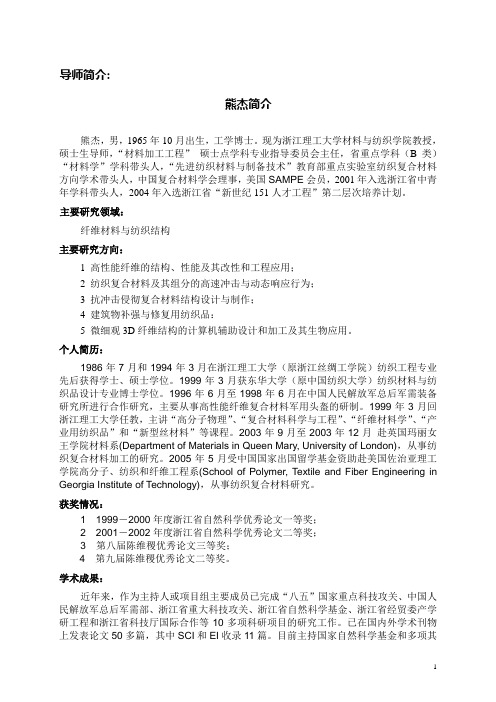
导师简介:熊杰简介熊杰,男,1965年10月出生,工学博士。
现为浙江理工大学材料与纺织学院教授,硕士生导师,“材料加工工程”硕士点学科专业指导委员会主任,省重点学科(B类)“材料学”学科带头人,“先进纺织材料与制备技术”教育部重点实验室纺织复合材料方向学术带头人,中国复合材料学会理事,美国SAMPE会员,2001年入选浙江省中青年学科带头人,2004年入选浙江省“新世纪151人才工程”第二层次培养计划。
主要研究领域:纤维材料与纺织结构主要研究方向:1 高性能纤维的结构、性能及其改性和工程应用;2 纺织复合材料及其组分的高速冲击与动态响应行为;3 抗冲击侵彻复合材料结构设计与制作;4 建筑物补强与修复用纺织品:5 微细观3D纤维结构的计算机辅助设计和加工及其生物应用。
个人简历:1986年7月和1994年3月在浙江理工大学(原浙江丝绸工学院)纺织工程专业先后获得学士、硕士学位。
1999年3月获东华大学(原中国纺织大学)纺织材料与纺织品设计专业博士学位。
1996年6月至1998年6月在中国人民解放军总后军需装备研究所进行合作研究,主要从事高性能纤维复合材料军用头盔的研制。
1999年3月回浙江理工大学任教,主讲“高分子物理”、“复合材料科学与工程”、“纤维材料学”、“产业用纺织品”和“新型丝材料”等课程。
2003年9月至2003年12月赴英国玛丽女王学院材料系(Department of Materials in Queen Mary, University of London),从事纺织复合材料加工的研究。
2005年5月受中国国家出国留学基金资助赴美国佐治亚理工学院高分子、纺织和纤维工程系(School of Polymer, Textile and Fiber Engineering in Georgia Institute of Technology),从事纺织复合材料研究。
获奖情况:1 1999-2000年度浙江省自然科学优秀论文一等奖;2 2001-2002年度浙江省自然科学优秀论文二等奖;3 第八届陈维稷优秀论文三等奖;4 第九届陈维稷优秀论文二等奖。

Hans Journal of Civil Engineering 土木工程, 2023, 12(6), 882-888 Published Online June 2023 in Hans. https:///journal/hjce https:///10.12677/hjce.2023.126100纤维复合材料(FPR)在锚杆领域的应用研究进展 孙权伟1,汤凯菱1,王梦稷21重庆科技学院建筑工程学院,重庆 2重庆交通大学土木工程学院,重庆收稿日期:2023年6月3日;录用日期:2023年6月23日;发布日期:2023年6月30日摘要 近年来,纤维复合材料(Fiber Reinforced Polymer, FRP)由于其优异的力学性能,逐渐在土木工程、矿山工程和岩土工程等领域中得到广泛应用。
作为一种新型结构材料,其具有重量轻、强度高、耐久性好等优点,受到越来越多领域的关注和青睐。
锚杆作为一种支护结构,广泛应用于地质灾害防治、深基坑支护、隧道开挖等领域。
对FRP 锚杆在力学性能、监测与识别、设计与锚固性能、锚杆拉拔破坏全过程、磁致伸缩导波技术应用、土层锚杆界面力学行为、危岩崩塌稳定性分析与治理、工作面帮支护性能试验、纤维材料筋制备及其增强混凝土结构、岩土锚固等方面进行了全面总结和分析,对FRP 锚杆未来的研究方向提供了参考和展望。
本文旨在对纤维复合材料在锚杆领域的应用研究进展进行综述。
关键词纤维复合材料,FRP 锚杆,力学性能,应用展望Research Progress in the Application of Fiber Composite Materials (FPR) in the Field of Anchor RodsQuanwei Sun 1, Kailing Tang 2, Mengji Wang 21School of Architecture and Engineering, Chongqing University of Science and Technology, Chongqing 2School of Civil Engineering, Chongqing Jiaotong University, Chongqing Received: Jun. 3rd , 2023; accepted: Jun. 23rd , 2023; published: Jun. 30th , 2023AbstractIn recent years, fiber reinforced polymer (FRP) has gradually been widely used in fields such as civil engineering, mining engineering, and geotechnical engineering due to its excellent mechani-孙权伟 等cal properties. As a new type of structural material, it has the advantages of light weight, high strength, and good durability, and has attracted more and more attention and favor from various fields. Anchor rods, as a support structure, are widely used in fields such as geological disaster prevention and control, deep foundation pit support, and tunnel excavation. A comprehensive summary and analysis were conducted on the mechanical properties, monitoring and identifica-tion, design and anchoring performance, the entire process of anchor rod pull-out failure, the ap-plication of magnetostrictive guided wave technology, the interface mechanical behavior of soil anchor rods, the analysis and treatment of dangerous rock collapse stability, the testing of working face support performance, the preparation of fiber reinforced steel bars and their reinforced concrete structures, and geotechnical anchoring. This provides a reference and out-look for the future research direction of FRP anchor rods. This article aims to summarize the re-search progress in the application of fiber composite materials in the field of anchor bolts.KeywordsFiber Composite Materials, FRP Anchor Rods, Mechanical Properties, Application ProspectsCopyright © 2023 by author(s) and Hans Publishers Inc. This work is licensed under the Creative Commons Attribution International License (CC BY 4.0)./licenses/by/4.0/1. 引言随着城市化和基础设施建设的不断推进,土木工程、矿山工程和岩土工程等领域对材料力学性能和工程效益提出了更高的要求[1]。