CAB 708 说明书--申克
- 格式:pdf
- 大小:767.40 KB
- 文档页数:74
CAB850CContents1. Splash (2)2. Printing 打印 (3)3. Unbalance display for unbalance measuring station不平衡测量工位的不平衡量显示: (4)4. Unbalance calibration of test shaft 试验轴的不平衡标定 (6)5. Test of unbalance calibration 不平衡量标定测试: (7)6. Unbalance measuring station drive adjustment 不平衡测量工位驱动调整 (8)7. Unbalance test I/O 不平衡量测试输入/输出 (12)8. Display the correction axes 显示校正轴 (13)9. Entry of axis position 轴位置输入 (15)10. Display the correction description 显示校正描述 (17)11. Test dialogue for a correction station 校正工位测试对话框 (22)12. Correction single-steps 单步校正 (26)13. Geometry display 几何显示 (28)14. Calibration of the geometry station 几何测量工位的标定 (29)15. Re-equip 重新设置 (33)16. Password (Service) 密码(服务) (37)17. Overview info 预览信息 (40)18. Backup 备份 (41)19. Emergency diskette 应急磁盘备份 (43)20. Configuration of the Type data 型号数据的配置 (44)21. Configuration of machine data 机器数据的配置 (46)22. Statistics 统计 (48)23. Statistics characteristic data 统计特性数据 (49)24. Class statistics 分组统计 (50)25. Mean value statistics 平均值统计 (51)26. Scatter-circle statistics 分散圆统计 (52)27. Standard deviation statistics 标准偏差统计 (53)28. CDM (54)29. Unbalance single step movement 不平衡单步动作 (56)1. SplashThe general layout of the user interface can be seen in the above graphic.用户界面总体布局图可以参见上述图解。

申克秤操作说明书第一章设备简介 (3)1.1申克秤简介 (3)1.2术语定义 (3)第二章设备结构 (5)2.1设备组成 (5)2.2注意事项: (6)第三章工作原理 (7)3.1申克秤计量原理 (7)第四章操作步骤 (10)4.1申克秤工作流程 (10)4.2申克秤操作条件 (10)4.3注意事项 (11)4.4压缩空气压力调节 (12)第五章检查维护及常见故障处理 (14)5.1检查维护 (14)5.2造成运行中煤粉秤的跳停的原因有如下几种 (37)5.3故障排除 (37)第一章设备简介1.1 申克秤简介申克秤是申克公司应用科里奥利原理开发的一种煤粉喂料计量系统。
煤粉由煤粉仓进入叶轮给料机时,首先经过内置搅拌器,被充分流态化,使其畅通,由叶轮给料机实现稳定喂料,进入科里奥利质量流量计被计量后进入煤粉输送管道,输送至窑头或分解炉。
测得的流量信号(实际值)输入MULTICONT测控系统,实际值与设定值在系统中进行比较,及时输出反馈信号,调节叶轮给料机转速,实现稳定喂料。
煤粉由流量计流出后,经过一段弯管进入输煤管道,由于喷嘴两边的正负压差(喷嘴位置需在安装调试时确定),这样煤粉可以较容易地被输送。
同时,从喷嘴靠罗茨风机端引出一条正压管线,对叶轮给料机内施加一个小的气压,使下料更为顺畅。
叶轮与外壳间隙仅0.2mm-0.35mm,被煤粉填充,可以保持叶轮给料机上下的压差,保证下料流畅及稳定。
该喂煤系统的叶轮给料机与煤粉仓出料管之间有一闸板用法兰联接,流量计与叶轮给料机出料管之间、流量计出料管与煤粉输送管线之间也用法兰联接,无需其它安装支架,安装高度低,安装和折卸维修方便;密封性能好,保持煤粉仓下的环境。
我公司12000TPD生产线共有三台申克秤,一台在煤粉制备车间供窑头燃烧器用煤,型号为Multicor-K120,两台在窑尾预热器处供分解炉用煤,型号为Multicor-K80。
1.2 术语定义Disocont: 煤粉秤计量仪表型号Multicell: 带搅拌器的星形喂料系统Multicor-K80: 煤粉秤计量单元型号,“K”代表煤粉计量系列,80为流经计量单元的物料流量为80m3/hAgitator: 搅拌器Star Feeder:星形下料器Optional Dryer:压缩空气干燥器Coriolis:科里奥立力Conveying Air:输送空气Compress Air:压缩空气Mode OP:本地操作模式Mode Normal: 中控操作模式V olume Mode: 容积方式Gravimetric Mode: 称重方式EasyServe10.0:Schenck: 提供的煤粉秤控制软件第二章设备结构2.1 设备组成Mulitcor-K80 煤粉秤煤粉计量系统外形如图1所示,Multicor-K80 系列组件按功能划分主要由四部分组成:2.1.1 MUTICELL rotary feeder (MUTICELL旋转喂料系统),由Integrated Drive(机电一体化驱动单元)和Star Feeder(星形回转下料器)组成,如图2所示。

电梯MPK708C调试-快车调试现场检查和确认(1)、机械装配检查及确认A、电梯底坑部件安装完好,若使用液压缓冲器,则应确认缓冲油是否按要求加足;底坑干燥。
B、井道内无影响电梯运行的障碍物。
C、厅门安装良好。
D、厅门立柱与门洞之间应封闭良好。
E、导轨安装已经检验合格。
F、钢丝绳安装正确,紧固。
G、各开关的安装和固定。
H、限速器钢丝绳涨紧轮安装正确。
I、轿厢安装完毕,拼装紧固。
J、随行电缆安装固定良好。
K、机房部件定位符合国家标准。
L、主机固定符合工厂的安装说明要求,并且主机大梁固定封闭(等隐蔽工程)到位。
M、若为有齿轮曳引机,应确认减速箱的油是否加到位。
N、应确认主机上的编码器固定是否牢固。
O、限速器定位应符合国家标准。
P、线槽敷设规整,线槽间有铜片或黄绿线连接。
Q、控制柜安装定位规整。
R、机房,井道保持整洁。
S、井道内每个楼层的平层感应器插板安装正确T、轿厢门机安装正确(2)、电气装配检查和确认注意A、门机接线应正确;光幕接线正确。
B、轿顶平层感应器接线正确,并安装尺寸正确、牢固。
C、井道内各安全开关能有效动作。
D、井道内上,下检测开关安装位置正确及开关动作有效。
E、对讲机接线是否正确,并确认通话正常。
F、到站钟接线应正确(无到站钟可省略此步)。
G、外呼盒的接线可靠,正确。
H、轿厢照明及风扇接线正确参数的检查和确认(1)、主控制器参数确认(举例说明)查看自学习以后以下参数的值,下面给出实验塔4#电梯的运行参数值:编码器脉冲数:2048rpm减速比:1:1变频器分频:8曳引机转速:234rpm门区板长度:220mm参数说明如下:注:井道换速开关的安装位置(即各梯速的换速距离)需严格按照系统标准规定距离进行安装使用,调试中严格保证硬件的安装位置确定以后,进行井道自学习后,不再更改换速开关的安装位置,即保证硬件和软件的换速距离一致.(2)、变频器参数确认确认变频器相应的速度设定值以及再次确认相关的运行参数。

DEM/DEL型定量给料机操作手册滁州安瑞汇龙电子有限公司第一章概述:1)概述DEM/DEL型定量给料机能自动按照预定的程序,根据设定的给料量自动调节流量使之跟踪设定值,以恒定的给料速率连续不断地输送散状物料,实现定量给料、自动计量和累计等功能。
DEM/DEL型定量给料机精度高、适应能力强、长期稳定性好可靠性高,尤其在条件恶劣的环境下能正常工作。
可广泛应用于水里、建材、矿山、化工、粮食等行业。
型号说明:DEM/DEL □□□□□□□料斗序号料斗型号(S、T、V)主从滚筒中心距(dm)皮带宽度(dm) M(重型)、L(轻型)定量给料机2)主要技术参数与功能:●给料精度:±0.5%●主电源:380Vdc10% ,50HZ2%●仪表电源:24Vdc±5%,1A●使用环境:秤体—30℃~ 70℃控制柜0℃~ 45℃●仪表型号:INTECONT PLUS VEG20610●模拟输入:流量设定值4 ~ 20mA●模拟输出:1.流量反馈4 ~ 20mA2.控制信号4 ~ 20mA●脉冲输出:+24V,100mA,脉冲宽度可调(50 ~ 1000ms之间),MAX 10Hz。
●开关量输入(无源):外部启动信号,释放信号等。
●开关量输出:MIN信号,MAX信号,故障信号,运行信号等。
●显示:荧光显示,2行20个字符,6mm高●能够显示故障信息●停电永久保持信息3)工作原理定量给料机主要由秤体、称重和测速传感器、控制仪表组成,对于粉状或粘湿性物料,尚需配置预给料机。
当系统进入正常工作状态,物料随皮带被拖出布于皮带的工作面上。
此时称量段上瞬时平均物料重G通过称量机构成线性关系作用在称重传感器上。
传感器所受的重力Pt为:Pt=CqtL (Kg)式中:qt:皮带称量段上的瞬时负荷(Kg/m)L:有效称量段长度(m)C:比例系数(又称结构系数)根据惠更斯桥路原理的电阻应变传感器,其电信号输出又与所受重力大小成正比。

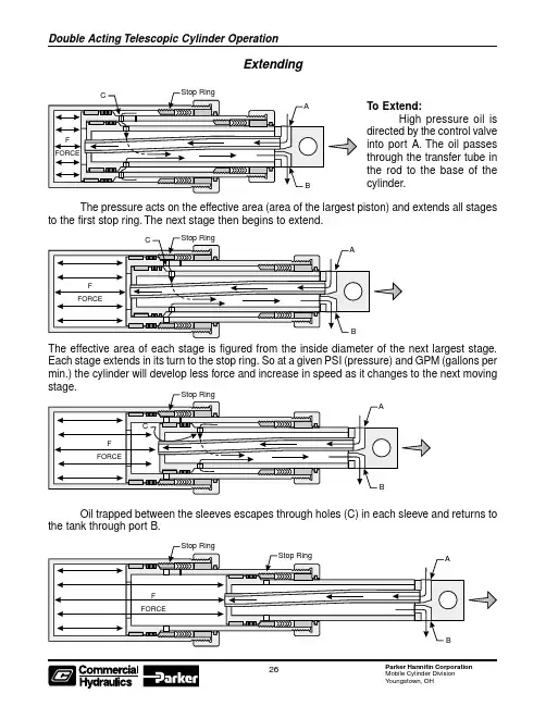
High pressure oil is ExtendingThe effective area of each stage is figured from the inside diameter of the next largest stage.Each stage extends in its turn to the stop ring. So at a given PSI (pressure) and GPM (gallons per min.) the cylinder will develop less force and increase in speed as it changes to the next moving Oil trapped between the sleeves escapes through holes (C) in each sleeve and returns to the tank through port B.High pressure oil is directed by the control valve into port B. The pressure is applied to the effective area (D) of the plunger which retracts first. Each stage from the smallest to the largestretracts in its turn, however, THE EFFECTIVE AREA FOR RETRACTING EACH ST AGE IS THE AREA (D) OF THE PLUNGER.Oil inside the cylinder is forced out of port A. Because of the area differential, the flow into port B must be multiplied by this differential to determine the flow out of port A. It may be neces-sary to install a dump-to-tank valve to speed up the retracting cycle.RetractingEquip your vehicle withthe world ’s besthydraulic cylinders Commercial HydraulicsWays to Extend the Life of Your Double-Acting Telescopic CylinderDouble-Acting Telescopic CylindersA double-acting telescopic cylinder should be fully retracted when not in use.A double-acting telescopic cylinder should not be extended until it has been fully retracted. A partially extended cylinder with pressure relieved may drift out of position. This can happen if a cylinder experiences vibration, such as an ejector or push out cylinder does in a refuse body. If this happens and the cylinder is then extended, the out of position plunger or sleeves will rapidly reposition themselves and possibly cause high pressure oil to be trapped on the retract side of the cylinder. This could cause a stage / sleeve to bulge and or the packing and bearings to be blown out from under a head nut.Do not operate a packer / ejector cylinder with a misaligned blade. If the packer / ejector blade is bent, damaged, or if the blade slide shoes or guide track assembly are worn out, this can cause excessive side loading to the cylinder damaging it internally or bending a plunger or sleeve.If the hydraulic system uses quick disconnects (such as on a transfer trailer) or holding / lock type valves, make sure they are properly connected. If not, oil may become trapped in the cylinder causing an excessive pressure build up and damage to the cylinder. This is particularly true if there is a blockage on the retract side of the cylinder and the cylinder is then extended. This could internally intensify the pressure 10 times or more inside the cylinder. (Example; The pump develops 2,000 P.S.I. trying to extend the cylinder, oil pressure trapped on the retract side of the cylinder could see 20,000 P.S.I.)Do not operate a cylinder at pressures above factory recommended operating pressures (Normally 2,000 P.S.I. unless otherwise approved). Make sure hydraulic pump is developing required G.P.M., Double-acting telescopic cylinders normally require 15 G.P.M. to retract properly.Most double-acting telescopic cylinders will self bleed themselves of air. Upon installation of a new cylinder this will require cycling the cylinder approximately 10 times to the complete extend and retract positions with no load against it. Check to make sure stages sequence properly. When extending, the largest stage should move first then the next largest, etc. and when retracting, the smallest should move first then the next smallest, etc.On Roll Off units, if the Lift Cylinders are not completely extended when a container is being pulled onto the hoist, the lift cylinders may be pulled open by the weight of the load. Then as the container is pulled over center, the cylinders will be forced closed until they hit the column of oil inside the cylinders causing a sudden pressure surge. If the lift cylinders are pulled open by the load, they should be extended with the control valve to fill them with oil before pulling the container on the rest of the way. Care should be taken if moving Roll Off unit with tilt cylinders extended, avoiding sudden stops or jolts.On Roll Off units dropping off a loaded container, feather control valve to avoid any pressure surges in the reeving / cable cylinders as gravity pulls the container to the ground.On Roll Off units, if the container is not evenly loaded and is heavy on one side, the lift cylinders may mis-stage. When the plunger / sleeves attempt to correct themselves, there may be a sudden pressure surge, possibly damaging the cylinder.。
a+ 条码机操作手册 适用a2+、a4+、a6+、a8+机型1. 碳带与卷标纸安装及卷标纸传感器位置调整1.1 碳带安装cab 条码机可使用内碳与外碳两种碳带,使用上的差别仅在于安装方向的不同,不需要更改机构,使用时注意安装方向即可;安装碳带步骤如下:1.一般新条码机都会附有一个纸卷,且置于碳带回收轴一端;2.于碳带供应轴一端安装新的碳带,从打印模块下方绕过印字头,切勿盖到标签纸感应器;错误的安装Æ碳带盖住感应器:3.在碳带供应轴上用胶带或贴纸将碳带固定,并多卷几圈;4.内碳的安装方向为:外碳安装方向为:1.2 标签纸安装标签纸安装步骤如下:1.将标签纸固定杆上的红色旋钮以逆时针方向转松并打开,再于标签纸卷横杆上装上标签纸卷,并由标签纸导引杆下方进入打印模块;2.转开印字头,将卷标纸由卷标纸传感器下方通过并放在滚轮上方,安装好标签纸卷后,放下卷标纸固定杆固定卷标纸卷,以顺时针方向转仅红色旋钮,再将标签导引轴上的红色固定环移到适合卷标纸大小的位置;外卷纸安装方向:内卷纸安装方向:错误的安装Æ卷标纸未从卷标纸导引杆下方进入打印模块:3.将标签纸导引杆上的红色固定环推到适合卷标纸宽度的位置;4.从打印模块进入时,切勿盖到标签纸感应器;错误的安装Æ从标签纸感应器上方进纸1.3 卷标纸传感器位置调整cab条码机可使用的标签纸型式有:连续式的卷标纸、具有间隔的标签纸、具有上标线或底标线的标签纸;在使用具有间隔的标签纸与具有上标线或底标线的标签纸时,需要将标签纸传感器调整到适当位置,条形码机才能正确打印标签,调整方式如下:①正确放入卷标纸到打印模块后,手指放在(3)的位置准备移动卷标纸传感器(2)②从条码机前方看标签纸传感器内的传感器小孔是否有对到标签纸的间隔处或间隔孔的位置,如使用上标线或底标线的标签纸,则要对到标线位置③确定有对准标签纸间隔处或间隔孔或标线位置后,卡上印字头,按下feed按键,测试看进纸是否正确,以便判断标签纸传感器是否能正确侦测到标签纸的间隔处或间隔孔或上/下标线。
申克仪表说明书1、目录1、概述 (1)讲述皮带秤操作原理及具体情况,如“出料点供料”。
什么是INTECONT? (1)详细资料 (1)定义 (1)计量原理 (1)控制 (2)输入和输出 (3)2、技术数据和字符 (5)本章简要介绍INTECONT 所用全部数据和所有可能发生的情况。
技术数据 (5)接口 (6)对话语言、单位 (7)显示、指示灯 (7)程序设置、标定 (8)3、程序设置 (9)程序设置功能便于以少量的运算完成秤体计量要求。
功能分配 (9)标定功能 (9)皮带环行LB (10)除皮TW (10)置零 (11)砝码检查CW (12)模拟方式 (13)时间设置.......................................... 13 4、服务值 (14)服务值信号适用外部线缆、输入、输出转换和负荷传感哭负载等检查。
另外,SPC值(生产过程控制统计)可用于喂料记录等方面。
5、参数 (15)确定设备特性,参数可满足特殊要求,甚至在停电时,他们亦能无限期的存贮。
总述 (17)调入参数 (17)装入初始参数 (18)参数概述 (19)注解参数表 (22)6、出现事件信号后错误诊断(故障信息) (45)大多数错误以及大部分操作状态均以事件信号的形式出现。
错误查询表帮助操作者迅速找出错误并及时恢复正常操作状态。
系统信息S…S9 (45)物料流量B…B9 (45)电气系统E…E5 (46)标定C1…C3 (46)最大值H1…L4 (46)最小值L1…L4 (47)信号灯 (47)7、使用 (48)全面介绍,逐步解释了应该进行的工作。
另外,你还会发现可能隐含的错误。
操作学习 (48)机械要求 (49)电器要求 (49)输入参数 (50)控制 (51)功能检查 (52)标定 (53)用砝码检查 (53)带速检查 (54)物料检查 (54)测试插座 (55)机械部分安装与调试 (55)1、概述什么是INTECONT?INTECONT PLUS是用于计量、控制、喂料设备的计量计算系统。
“H” ISO Series ValvesFeatures 5599-2 – Size 1, 2, 3Catalog 0632-6/USACollective Wiring SystemCollective Wiring ModuleSizeKit Number 25-Pin, D-Sub Module*†SCD251MB 19-Pin Heavy Duty Round*†SCC191MB Dual 12-Pin Round - DC*†SCC122MB Dual 12-Pin Round - AC*†SCC122NB D-Sub Cable, Non-IP , 3 Meters †SCD253D D-Sub Cable, IP65, 3 Meters †SCD253W*Kit includes:(1) Wiring Module with Circuit Board Connection,(2) Gaskets, (4) Tie Rods and (4) Bolts.†Available with “H” Series, ISO 5599-2, Sizes 1, 2, 3.Features•Interconnect Manifolds •25-Pin, D-Sub – 24 Addresses •19-Pin Round – 16 Addresses •Dual 12-Pin Round – 16 Addresses •FlexSAM Serial Bus – 32 Addresses •SAM 3.0 Serial Bus – 4 Addresses •Manifold Additions for In-Field Conversions,Plug “N” Play25-Pin, D-Sub Collective Wiringwith FlexSAM SystemSCD251MBSCC191MB25-Pin, D-Sub Collective Wiring19-Pin Heavy Duty WiringDual 12-Pin Collective Wiringfor AB Panel ConnectAllen-Bradley Panel ConnectSCC122MB (Dual 12-Pin – DC)orSCC122NB (Dual 12-Pin – AC)25-Pin, D-Sub Cable Non-IP, 3-Meter ...SCD253D IP65, 3-Meter......SCD253WSCC122MB (Dual 12-Pin – DC)orSCC122NB (Dual 12-Pin – AC)5599-2 End Plate & Transition Plate KitsCollective Wiring System Blank InterfaceTop Port InterfaceGround ScrewInterface plate includes a machined hole for the addition of a ground screw. An earth ground is recommended for all voltages. Follow standard electrical protocol.How to Assemble a Collective Wiring Add-A-FoldTop PortH3H2H1CW Left Hand Interface Plate - Blank and PortedH1 H2H1 H35599-2 Pin Out InformationCollective Wiring System25-Pin, D-Sub Cable SpecificationsCommon Pin “13” is rated for 3 amps. Common wire ratingmust be greater than total amperage of all solenoids on a Add-A-Fold assembly.Example: 12 station manifold, 24 solenoids,24VDC - 24 x .095 amps = 2.28 total amp rating.IP65 rated with properly assembled IP65 rated cable.25-Pin, D-Sub Connector (Male)19-Pin Round Cable SpecificationsCommon Pin “7” is rated for 8 amps. Cable common wire must be greater than total amperage of solenoids on Add-A-Fold assembly.Example: 8 station manifold, 16 solenoids,120VAC - 16 x .039 amps = .63 total amp rating.NEMA 4 rated with properly assembled NEMA 4rated cable.Female Cable Assemblies:Refer to 19-Pin Round Brad Harrison11211131415161718192348910576Pin Number 11121 1516171819Address9Ground 10111213141516Pin Number12345678910Address1234N/A 5Common678Technical SpecificationsMaximum Solenoids Energized SimultaneouslyDualVoltage 25-Pin 19-Pin 12-Pin FlexSAM SAM 3.0Code D-Sub Round Round12VDC 151816N/A N/A N/A 24VAC 122416N/A N/A N/A 24VDC 1924161632*4120VAC 23, 83241616N/A N/A Brad Harrison #333030P80M05016.40 ft. (Female to Male Cable)Brad Harrison #333030P80M010032.80 ft. (Female to Male Cable)*The maximum number of addressed solenoids for FlexSAM is 26through the interconnect system. For 28 through 32 addressed solenoids all bases are “hard-wired” and valves have to be selected with the terminal block option.Dual 12-Pin Round Allen-BradleyFace View - Male 19-Pin ConnectorAllen Bradley #889N-F12ACNU-2 2 Meter (Female to Male Cable)Allen Bradley #889N-F12ACNU-3 3 Meter (Female to Male Cable)Allen Bradley #889N-F12ACNU-5 5 Meter (Female to Male Cable)Allen Bradley #889N-F12ACNU-1010 Meter (Female to Male Cable)AB Panel Connect Patch Cord Assemblies:Patch Cord good for 24VDC & 120VACFor availability & Specs, contact an Allen-Bradley Distributor25-Pin, D-Sub Cable (Female)1Black14 Color Brown / White Color Pin NumberPin Number。
TOOLSGenerations of proud professionals have developed their skills together with Bahco tools since 1886 and already in the middle of last century Bahco has been synonymous with high quality air tools.We are proud to present a strong comeback in the air tools business with a range of unique products. A range that incorporates Bahco's spirit of innovation and unrelenting quality. A range of silent yet powerful, powerful yet lightweight, lightweight yet durable tools, designed for high demands, from the toughest job to the most accurate precision job, from the smallest car to the largest truck.In other words a complete range of professional air tools for everyday use!AIR TOOL ICONSLIGHTWEIGHT YET DURABLEBAHCO - THE CHOICE OF TRUE PROFESSIONALSPRODUCT CODEHOSE DIAMETER / RECOMMENDED M IN. mmPACKAGING DIMENSIONSmmTORQUE RANGENmMAXIMUM T ORQUE IN REVERSE MODENmMAXSPEED - REVOLUTIONS PER MINUTE / STROKES PER MINUTEmin -1SOUND PRESSUREdBAAIRCONSUMPTIONl / minENGINE OUTPUTDRIVEinchTHE CHOICE IS YOURS!THE CHOICE IS YOURS!THE CHOICE IS YOURS!10mmBPM915100x250x2501/210988139.800≤ 102,55,11781/410 2,20kgmm NmNmMAXmindBA m/secl/mininch mm10mmdBAdBA dBANmMAXNmMAXNmMAX%%%%Nm%Nm%NmMufflerMuffler MufflerfflerMuffIMPACT WRENCH 1/2”IMPACT WRENCH 3/8”MINI IMPACT WRENCH 1/2”ffMufconsumption in no time extreme durabilitySupplied with a black vinyl protection bootMAINTENANCE FREE!We know you DON’T have time to lubricate your gun.Now you DON’T have to feel guilty about it becauseyou DON´T NEED TO DO IT!The exceptional OIL BATH lubrication system withhigh grade synthetic racing oil ensures aMAINTENANCE FREE TOOL and LONG LIFETIMECONFUSED?FORWARD? REVERSE?MAX? MIN?Change DIRECTION and POWERoutput in 1 SECOND with ONE HAND!No need to WASTE TIME by USINGTWO HANDS any moreEXTRA SILENT & POWERFUL orEXTRA POWERFUL & SILENT?The system with optional muffl ers gives YOU the CHOICE toquickly adapt the tool to YOUR DEMANDS and needs! Use0, 1 or 2 of the included muffl ers! With no muffl er the power ismaximized, with 2 muffl ers the sound is minimized01098 Nm102.5 dBA11015 Nm-7,6%92.5 dBA-316 %2935 Nm-14,8%86.6 dBA-623 %0440 Nm96.6 dBA1414 Nm-6%90.3 dBA-275 %0440 Nm99.1 dBA1414 Nm-6%90.3 dBA-275 %mm10 BP814 merely 1.2 kg and striking a maximum3/8” IMPACT WRENCH SETIncludes:mm10BP817100x290x2503/4 1.800340-950 4.500884,301903/8103,95kgmmNmNmMAXmin dBAm/sec l/mininchmmkgBP81578x215x2101/2825320-6207.000845,001301/4101,95mmNmNmMAXmin dBAm/sec l/mininchmmBP815K1108x371x32110-243,20mmkgFOR THE LARGE ONES!BP900L impressive 2.800 Nm!• Composite housing• Twin hammer mechanism • Air exhaust in handle• Composite housing• Twin hammer mechanism • Air exhaust in handle • Swivel connectionIncludes:• One BP815• Eleven impact sockets• One 1/4” threaded male coupler• Supplied in robust plastic case with foam inlay (compatible with Bahco tool trolley modular system, T12)IMPACT WRENCH 3/4”1/2” IMPACT WRENCH SET10mm13mm13mm13mm10mm10mm• Heavy duty modelRATCHET 1/2”dBANmMAX 95 Nm 94.9 dBA 67 Nm-30%87.9 dBA-224%%%NmMufflerBP92170x330x903081/27-95200≤ 94,9≤ 5,21271/4101,35kgdBAm/sec l/mininch mmNmmin mmmm BP91950x280x1001981/40-47235842,5401/4100,59kgNmmin dBA m/sec l/mininch mmmmmmBP92050x280x1001983/80-47235842,5403/810 0,59kgNmmin dBAm/sec l/mininch mmmm mmMUFFLER BYPASS SYSTEMDEMANDS and needs!ratchet pawl lock up and assuresincreased tool lifeMINI RATCHET 1/4”• Soft grip handle• Hard coated motor plates • Large lightweight selector knob• All ball bearing construction and high strength alloy steel gear system • Supplied with a black protection bootMINI RATCHET 3/8”• Balanced lightweight housing • Soft grip handle• Hard coated motor plates • Large lightweight selector knob• All ball bearing construction and high strength alloy steel gear system • Supplied with a black protection bootWHEN ACCESSIBILITY & POWER IS CRUCIAL10mm10mmTop mounted forward / reverse switch allowing one hand operation for easy usageUser friendly design with fore The 0,45 HP motor with 5 vanes provides MAXIMUM DRILLING POWER to get the jobNEED FOR CONTROL?REVERSIBLE VARIABLE SPEED TRIGGER for increased control of drilling speedALSO A PERFECTIONIST?Precise 0,0635 mm CHUCK RUNOUT for precision drilling yielding a high quality job,HIGH PRECISION DRILL 13 mm REVERSIBLE DRILL 13 mm• Composite housing• Removable and adjustable handle10mmBP21265x280x8510x330 24616.000 83<2,503901/4100,80Belts 25 pcs 80 grits - Suitable for BP212BPN21201kgmmmin dBAm/sec l/mininchmmmmBelts 25 pcs 100 grits - Suitable for BP222BPN22201PISTOL GRIP SANDER BP204120x570x238168325.000854,531700,50kgmmmin dBAm/sec l/minPISTOL GRIP SANDER SETBP601105x210x145511.000 22415280<2,502551/4100,80kgmmmin dBAm/sec l/mininchmmmmmmBP22265x280x85 20x520 32816.000 85,53,203901/410 1,10kgmmmin dBAm/sec l/mininchmmmmBP51137BP610105x210x1452,511.000 224 15280<2,502551/4100,80Pad - Suitable for BP601 and BP610kgmmmin dBAm/sec l/mininchmmmmmmL GRIP SANDERBP2044PAD BELT SANDER 10 mm • Adjustable arm• Including three belts 80, 100 and 120 gritsBELT SANDER 20 mm• Adjustable arm• Including two belts 100 and 120 gritsORBITAL SANDER 5 mm • For central vacuum systems • Composite housing• Top mounted speed change switchORBITAL SANDER 2,5 mm• For central vacuum systems • Composite housingIncluding:mm10mm10mm1.800 RPM WHEN T OT AL CONTROL IS A MUST!WHEN REAL POWER IS A MUST!With its speed of 10.000 revolutions per minute the BP823 gets the job done in no timeBP125349x543x3971913301/4102,0kgmminch mmStroke (mm)Traction power (kg)BP11750x243x172373 2.500854,531701/4101,0kgmmmin dBAm/secl/mininch mmExhaust hose for die grinderBP117EH10mm10mmAIR RIVETERLOW REVOLUTION GRINDER DISC GRINDER • Composite housing • Safety triggerCUT OFF TOOL• Speed control system • Rubber sleeve • Safety trigger • Swivel connection• Rivet capacity;3,2 mm 4,0 mm 4,8 mm 6,4 mm• Speed control system • Hexagonal rubber sleeve • Safety triggerBP421M BP430M BP431M BP432M BP433M BP434M10mm10mm10mm10mm10mmmm10• Hexagonal rubber sleeve CARTRIDGE APPLICATOR• Enables fast and ef fi cient application • Heavy duty For Bahco's extensive range of rotary burrs suitable forBP822, BP822E and BP115 please see the Bahco catalogue, BP218 19x200x85≤ 11 158 1/4 0,15kgmml/mininch BPHVLP01155x225x2002-2.86002501/4 5-400,70kgmml/mininchCup size(ml)°CBP909K108x371x32110229 2.500941,5601/4102,1kgmmmindBA m/secl/mininch mmmm mmAccessory chisels - Suitable for BP909KBP909TF Turning, fl at Round 10.2mm YesBP909TWF Turning, wide fl at Round 10.2mm YesBP909TTP Turning, tapered punch Round 10.2mm YesBP909TE Turning, edge claw Round 10.2mm YesBP909TH Turning, hammer Round 10.2mmBP909TSP Turning, straight punch Round 10.2mm YesBP909NF Non - turning, fl at Round 10.2mmBP909NE Non - turning edge claw Round 10.2mmType Shank Included i nBP909K The unique quick chuck makes chisel changea piece of cakeDURABLE & SMARTBuilt of only the most heavy duty materials,solid HIGH GRADE STEEL BARREL,KEVLAR reinforced fl utter disc, INBUILT AIRFILTER. All to ensure MAXIMUM TOOL LIFESO SMOOTH...Even if the power is tremendous, the vibration is nominal. ONLY 1.5m/s2thanks to the dual elastomer cushions that absorb almost all vibrationHARD HITTING!The 76 MM LONG STROKE of the EXTRAHEAVY HARD STEEL PISTON ensures strikingpower as you have never experienced beforeEASY HANDLINGBuilt in four position air regulator and direct multi-portfrontal exhaust ensures comfortable usageSupplied in robust plastic case including FIVECHISELS for a wide area of applications THE SLUGGER! AIR HAMMER SETBLOW GUN• Steel nozzle• Meets O.S.H.A requirements• Brass inletPAINT GUN SET• High volume at low pressure• High precision provides highquality painting• Spare nozzle sets coveringfi ve diameters• No seal component design formuch longer operation life• Precise air cap keeps theoutlet less than 10PSI• One piece aluminum housingWHEN FLEXIBILITY IS A MUST!ISO6150BARO210European(German)Italian• Works with four standard male connector profi les• Security lock enabling the operator to turn on and off the aired operation Thanks t o t he d ouble c ollets i ncluded i n t he• Robust designmm10mm10-13BP79917x200x17 13.00078<2,00281/410 0,22Spare tip - Suitable for BP799BP79912BPHRS1315519x614x264 13/2015 1/2-1/2 24BPHR1315509x539x239 13/16151/2-1/29,70BPHR1020509x539x23910/14,5203/8-3/89,70BP25480x290x801-8,5 1,5 -5/+60≤ 3.800 200 1/20,80kgmmmin dBAm/sec l/mininchmmkgmminchmmmkgmminchmmmkgmminchAdjustable pressure range(bar)Maximum service pressure(MPa)°C Bowl capacity (ml)• For fast and secure marking • Low vibration• Low air consumptionIN LINE MINI LUBRICATOR• Lubricates the air to ensure correct operation and longer lifetime of the air tools• Corrosion resistant• Adjustable double guide arm • Ball bearing swivel • Strengthened frame • 110º swivel base• Positive latching system which automatically locks the hose at desired length for increased functionality and comfortAIR HOSE REELS• 180º swivel bracket• Detachable pin swivel• Durable corrosion and rough environment resistant polypropylene housing• Positive latching system which automatically locks the hose at desired length for increased functionality and comfortAIR FILTER - REGULATOR• Filters the air to avoid damage caused by dust • Regulates desired pressure between 1 and 8,5 barAIR FILTER - REGULATOR -LUBRICATOR• Filters the air to avoid damages caused by dust • Regulates desired pressure between 1 and 8,5 bar• Automatically lubricates the air to ensure correct operation and longer lifetime of the air toolsl/minK7760C-1K7760C-2K K 3/8” Impact ball joint3/8” Impact adaptors, bit holderK7806M-1010K7806M-1111K7806M-1212K7806M-1313K7806M-1414K7806M-1616K7806M-1717K7806M-1818K7806M-1919K7806M-2121K7806M-2222K7806M-2323K7806M-2424K7806M-2727K7806M-3030K7801Z-3/83/8K7801Z-7/167/16K7801Z-1/21/2K7801Z-9/169/16K7801Z-5/85/8K7801Z-11/1611/16K7801Z-3/43/4K7801Z-13/1613/16K7801Z-7/87/8K7801Z-15/1615/16K7801Z-11K7801Z-1.1/16 1.1/16K7801Z-1.1/8 1.1/8K7801Z-1.1/41.1/4K7806Z-3/83/8K7806Z-7/167/16K7806Z-1/21/2K7801Z-9/169/16K7801Z-5/85/8K7801Z-11/1611/16K7801Z-3/43/4K7801Z-13/1613/16K7801Z-7/87/8K7801Z-15/1615/16K7801Z-11K7801Z-1.1/16 1.1/16K7801Z-1.1/8 1.1/8K7801Z-1.1/4 1.1/4K7801Z-1.5/16 1.5/16K7801Z-1.3/8 1.3/8K7801Z-1.7/16 1.7/16K7801Z-1.1/21.1/2K7806M/S417-24D/S10280x160x7010-19D/S14280x160x7010-27mmDD/S10280x160x7010-19DD/S14375x215x10010-27mmD-DD/S20375x215x10010-19mmK7806Z/107/16-11/2” Impact sockets metric deep1/2” Impact sockets TORX®1/2” Impact sockets imperial1/2” Impact sockets imperial deep1/2” Impact socket set metric deep1/2” Impact socket sets metric1/2” Impact socket sets metric deep1/2” Impact socket set + metric deep1/2” Impact socket sets imperial, 10 pcsD/S10D/S14DD/S10DD/S14D-DD/S201/2” Impact ball joint1/2” Impact adaptors, bit holder3/4” Impact ball jointK560F-7119-70K560F-81 & 1.1/275-80 & 46-90K9501Z-11K9501Z-1.1/16 1.1/16K9501Z-1.1/8 1.1/8K9501Z-1.3/16 1.3/16K9501Z-1.1/4 1.1/4K9501Z-1.5/16 1.5/16K9501Z-1.3/8 1.3/8K9501Z-1.7/16 1.7/16K9501Z-1.1/2 1.1/2K9501Z-1.9/16 1.9/16K9501Z-1.5/8 1.5/8K9501Z-1.11/16 1.11/16K9501Z-1.3/4 1.3/4K9501Z-1.13/16 1.13/16K9501Z-1.7/817/8K9501Z-1.15/16 1.15/16K9501Z-22K9501Z-2.1/8 2.1/8K9501Z-2.3/16 2.3/16K9501Z-2.1/4 2.1/4K9501Z-2.5/16 2.5/16K9501Z-2.9/16 2.9/16K9501Z-2.3/42.3/4K9506M-2222K9506M-2424K9506M-2727K9506M-3030K9506M-3232K9506M-3333K9506M-3434K9506M-3636K9506M-3838K9506M-4141K9506M-4646K9506M-5050K9506M-5555K9506M-6060K9506Z-11K9506Z-1.1/16 1.1/16K9506Z-1.3/16 1.3/16K9506Z-1.1/4 1.1/4K9506Z-1.7/16 1.7/16K9506Z-1.1/2 1.1/2K9506Z-1.5/8 1.5/8K9506Z-1.13/16 1.13/16K9506Z-1.7/81.7/8K9567S11K8909ML-1212K8909ML-1414K8909ML-1717K9509ML-1919K9509ML-2222K9509ML-2424K9560G-112511K9560G-217511K9560G-332511mmBHVIS0895SCANIA F WHEEL-8F X 95MM-3/43/4BHVIS08100SCANIA R WHEEL-8F X 100MM-3/43/4DescriptionBHVIS08115VOLVO WHEEL-8F X 115MM-3/43/4Description1” Clamping springs1” Impact sockets imperial1” Impact sockets metric deep1” Impact sockets imperial deep1” Impact ball joint1” Screwdriver bits for hexagon metric socket head screws1” Impact extensionsImpact sockets Scania• Special impact sockets to use for Scania truck wheels • Output:• HVIS0895: 8 fl utes x 95 mm for front wheels • HVIS08100: 8 fl utes x 100 mm for rear wheels• Special impact sockets to use for Volvo truck wheels Impact socket VolvoBHVIS111BPW12BHVIS120BPW16BHVIS109BPW12BHVIS80BPW12Special torsion bars for controlling the torque applied to wheels and other partsBH BHBH BH Textured PU gloves with additional padded cells to give protection whilst using。
Operating Instructions & Parts ManualModel NumberHW93657HW93667HW93660HW93662Service JacksHW93657/ HW93660HW93667/ HW93662Capacity4 Ton4 Ton Air/ Manual10 Ton10 TonAir/ ManualMade inNorth AmericaSave These InstructionsFor your safety read, understand, and follow the information provided with and on this jack. The owner and operator of this equipment shall have an understanding of this jack and safe operating procedures before attempting to use. The owner and operator shall be aware that use and repair of this product may require special skills and knowledge. Instructions and safety information shall be conveyed in the operator's native language before use of this jack is authorized. If any doubt exists as to the safe and proper use of this jack, remove from service immediately.Inspect before each use. Do not use if there are broken, bent, cracked, or damaged parts (including labels). Any jack that appears damaged in any way, operates abnormally, or is missing parts, shall be removed from service immediately. If the jack has been or is suspected to have been subjected to a shock load (a load dropped suddenly, unexpectedly upon it), immediately discontinue use until the jack has been checked by a Hein-Werner authorized service center. It is recom-mended that an annual inspection be done by qualified personnel. Labels and Operator's Manual are available from manufacturer.PRODUCT DESCRIPTIONHein-Werner Hydraulic Service Jacks are designed to lift, not sustain, rated capacity loads. They are designed to be used in conjunction with jack stands. Intended use: To lift one wheel or one axle of a vehicle for the purpose of service and/or repair of vehicle components. After lifting, loads must be immediately supported by appropriately rated jack stands. Check with vehicle owner's manual for proper lift points.DO NOT USE TO DOLLY OR MOVE VEHICLE.DO NOT USE FOR ANY PURPOSE OTHER THAN THOSE USES OUTLINED ABOVE !SAFETY INSTRUCTIONSBEFORE USE1.Verify that the product and application are compatible, if in doubt call Hein-Werner technical service.2.Read the operator's manual completely and familiarize yourself thoroughly with the product, its components and recognizethe potential hazards associated with its use before the use of this product.3.Follow assembly instructions4.Lower saddle fully.5.Locate and remove the air vent screw.6.Ensure the oil level is within ~ 3/16" from the inner cylinder as viewed from the air vent screw hole.7.Reinstall the air vent screw.8.Close release valve by turning the release knob clockwise until firm resistance is felt.9.Ensure that the jack rolls freely.10.Raise and lower the unloaded saddle through out the lift range before putting into service to ensure the pump and releasevalve operate smoothly.11. Replace worn or damaged parts and assemblies with Hein-Werner Replacement Parts only. (See Replacement PartsSection). Lubricate as instructed in Maintenance Section.•Study, understand, and follow all instructionsprovided with and on this device before operating thisdevice.•Do not exceed rated capacity.•This is a lifting device only.•After lifting, immediately transfer the load toappropriately rated vehicle stands.•Never work on, under, or around a load supported bythis device.•Use only on hard, level surfaces capable ofsustaining rated capacity loads.•Do not move or dolly loads with this device.•Do not modify this device.•Do not use adapters or accessories that are notprovided initially.•Lift only on areas of the vehicle as specified by thevehicle manufacturer.•Failure to heed these markings may result inpersonal injury and/or property damage.ASSEMBLYEQUIPMENT NEEDED FOR ASSEMBLY:1.Needle nose locking pliers2.Snap-ring pliers (for: HW93657 and HW93667 only)3.15 /16“ wrench (for: HW93660 and HW93662 only)4.Hammer5.Tape measure6.All necessary hardware is included and is assembled loosely onto the jackASSEMBLY INSTRUCTIONS:1.Remove the service jack base and handle from the carton.2.For HW93657and HW93667, see figure 1 to remove the retaining ring and the handle pivot pin from the jack base thatconnects through the handle fork. For HW93660 and HW93662 (as shown in figure 2) remove the 5/16-18 bolts and the pin from the jack base that connects through the handle fork.3.Remove the #6-32 screw and nut from the universal receptacle on top of the hydraulic unit.4.Pull the universal assembly, located on the bottom of the handle, out a minimum of 1-3/4".5.Clamp the needle nose locking pliers onto the rod so that the universal assembly will not retract back into the handle.6.Slide the universal assembly into the handle socket so that it extends out the other side.7.Push the pivot pin that was removed in step 2 back through the handle and handle socket (may have to gently tap thepin with a hammer).8.Align the pivot pin with the holes on the side plates that the pivot pin was removed from and tighten the 5/16"-18 boltsinto the pivot pin until secure. (for HW93660 and HW93662 only)9.Connect the universal assembly to the universal receptacle rod using the #6-32 screw and nut from note 3 (fingertighten only).10. Remove the needle nose locking pliers.11.Jack is now operational and ready for use.Helpful hint:If the jack cover is a hindrance, it can be removed by using a 1/8" punch and taping out the pivot pins (be sure to attachthe cover back to the jack after assembly is completed).OPERATIONLifting1.Place the vehicle in the park gear.2.Engage the emergency brake.3. Chock the wheels securely to prevent inadvertent vehicle movement.4.Locate and close the release valve by turning release knob clockwise, firmly.5. Center jack saddle under lift point. Refer to the vehicle manufacturer owner's manual to locate approved lifting points on the vehicle.6.Verify lift point then use handle pump to contact lift point. To lift, pump handle until load reaches desired height.7.Transfer the load immediately to appropriately rated jack stands.Lowering1.Raise load high enough to clear the jack stands.2.Remove jack stands, carefully. (always used in pairs).3.Slowly turn the release knob counterclockwise, but no more than 1/2 turn. If the load fails to lower:e another jack to raise the vehicle high enough to reinstall jack stands.b.Remove the malfunctioning jack and then the jack stands.c. Using the functioning jack, lower the load by turning the operating handle counterclockwise, but no more than 1/2 turn.4.Push saddle down to reduce ram exposure to rust and contamination after removing the jack from under the load.Figure 3 - HW93657/ HW93660 NomenclatureFigure 4 - HW93667/ HW93662 NomenclatureLift ArmFigure 1 - HW93657/ HW93667Figure 2 - HW93660/ HW93662Air HoseSaddleHandleLift ArmHandle ForkCasterFront WheelRelease KnobSaddleHandleRelease KnobCasterAir MotorAir Vent Screw(on the power unit)Air Vent Screw (on the power unit)Handle ForkLift ArmMAINTENANCEImportant: Use only a good grade hydraulic jack oil. Avoid mixing different types of fluid and Never use brake fluid, turbine oil, transmission fluid, motor oil or glycerin. Improper fluid can cause failure of the jack and the potential for sudden and immediate loss of load. We recommend Hein-Werner hydraulic jack oil HW 93291.Adding oil1. Lower saddle fully.2.Set jack in its upright, level position.3. Locate and remove air vent screw.4.Fill with oil until ~3/16" above the inner cylinder as seen from the air vent screw hole.5.Reinstall the air vent screw.Changing oilFor best performance and longest life, replace the complete hydraulic fluid at least once a year.1. Lower saddle fully.2. Remove the air vent screw.y the jack on its side and drain the fluid into a suitable container.Note: Dispose of hydraulic fluid in accordance with local regulations.4.Fill with oil until ~3/16" above the inner cylinder as seen from the air vent screw hole.5.Reinstall the air vent screw.LubricationA periodic coating of light lubricating oil to pivot points, axles and hinges will help to prevent rust and assurethat wheels, castors and pump assemblies move freely.CleaningPeriodically check the pump piston and ram for signs of rust or corrosion. Clean as needed and wipe with an oily cloth. Note: Never use sandpaper or abrasive material on these surfaces!StorageLower the saddle to its lowest position when not in use.TROUBLESHOOTINGModel HW93657 Replacement PartsFigure 5 - Parts Illustration for Model HW93657Model HW93657 Replacement Parts (cont.) - Hydraulic UnitFigure 6 - Parts Illustration for Model HW93657 (Hydraulic Unit)Model HW93657 Replacement Parts ListPart# Description Qty.200003h Gasket1 200472Screw2 201110Lockwasher4 201479Lockwasher2 201733Plug1201779Lockwasher2 201784Lockwasher1 201808Rivet2 203198h Ball (7/32" O.D.)1 203199h Ball (1/4" O.D.)1 203200h Ball (9/32" O.D.)1 203201h Ball (5/16" O.D.)1 203205h Ball (7/16" O.D.)1 203299Jam Nut4 203313Jam Nut2 203332Nut1 203344Jam Nut2 204270Washer2 204277Washer1 204301Washer1204303Washer1 204343Washer4 204372Washer1 204444Cotter Pin3 204461Cotter Pin1 204842h Copper Gasket1 209964Lockwasher2 210225Spacer1 210311Pipe Plug3 210411h Washer1 211341Rivet1 212227Release Valve1 213152h Packing Ring2 213171h Packing Ring2 214538Groove Pin4214555h O-ring1 214699Bushing1 214700Handle Segment Assy.1 216645Pin1 216646Pump Pin1 218988Roll Pin1 219451Hex Nut2 220769Cross Pin1 221739h Poppet1 221740Ball Stop Plug(7/16" L)1Part# Description Qty.221742Ball Stop Plug (3/4" L)1221764h Ram Quad Ring1221766Cylinder1221770Low Pressure Pump1221771h Washer1221772h Quad ring1221778Washer4221781Handle and Cross Bar1221798Retainer Ring4221817Retainer Ring2221823Parallel Link2221825Parallel Link Pin1221829Pin1221937Turning Knob1221938Roll Pin1222095Release Stem Kit1222098Speed Pump Assy.1222201h Spring1222257Plug Poppet Valve2222533h Screen2223166h Ram Screen1226314Gland Nut1226318Grease Fitting1226319Bellcrank Pin1226324Pressure Plug1226325Pump Link2226326Nut1226327Slotted Tube1226329Pin1226331h Spring1226353h Spring1226366Hex Head Bolt1226372Spring1226615Front Wheel2227395Plunger Assy.1227397Release Link1227399Extension Rod1227436Turning Rod Assy.1228257h U-cup1228354Universal Assy.1228875Spring1228881Grip2229392Serial Plate1229748h Heel Plate3229749Washer1Part# Description Qty.229750Ram 1229751Pin 1230583Ram Assy.1231316Vent Valve Assy.1231583Rear Caster2231638Filler Screw1231710Oil Tank1232968h Back-up Washer1232969h U-cup1232970Pressure Pump1232971Pressure Pump Kit1233798Tank Nut1233880Tank Nut and Quad Ring1233917h Plastic Spring1233921Release Stem1234976Cap Housing1241885Bellcrank1241887Handle Socket1241889Liftcap1241893Sideplate Assy1241894Sideplate Assy1241895Hydraulic Unit Cover1241907Repair Kit (Hyd. Unit)-241956Fulcrum Pin1241983Sideplate Tie Rod2241985Support Rod1241986Front Axle1241987Retainer ring2241988Handle Pivot Pin1241989Extension Spring2241990Handle Assy.1241991Hydraulic Unit Casting1241993Hydraulic Unit Assy.1HW93657-K0 Label Kit (not shown)HW93657-M0 Manualh Included in Repair Kit 241907Model HW93660 Replacement PartsFigure 7 - Parts Illustration for Model HW93660Model HW93660 Replacement Parts (cont.) - Hydraulic UnitFigure 8 - Parts Illustration for Model HW93660 (Hydraulic Unit)Model HW93660 Replacement Parts ListPart# Description Qty. 200003Gasket1 200472Bolt2 201110Lockwasher4 201115Lockwasher2 201481Lockwasher2 201733Expansion Plug1 201784Lockwasher1 201789Lockwasher2 203198h Ball1 203199h Ball1 203200h Ball1 203201h Ball1 203207h Ball1 203272Nut2 203297Nut2 203299Nut2 203323Nut2 203332Nut1 203344Nut2 204270Washer2 204277Washer1 204301Washer1 204303Washer1 204372Washer1 204444Cotter Pin4 204461Cotter Pin1 204842h Gasket1 207169Nut2 209964Lockwasher2 210225Spacer1 210311Pipe Plug3 210411h Washer1 211341Rivet1 212227Release Valve1 212689Bolt2 213152h Packing Ring2 213171h Packing Ring2 214538Groove Pin4 214555h O-ring1 214699Bushing1 214700Handle Segment1& Bushing216645Pin1 216646Pin1 217653Roll Pin2 218988Roll Pin1 218991Roll Pin1Part# Description Qty..220769Cross Pin1221739Poppet1221742Ball Stop Plug1221770Speed Pump1221771h Back-up Washer1221772Quad Ring1221781Handle & Cross Bar1221809Handle Grip2221937Release Knob1221938Roll Pin1222095Release Stem Assy.1222098Speed Pump Assy.1222201h Spring1222257Plug1222533h Screen2223166h Screen1224253Cover1226271Fulcrum Pin1226314Gland Nut1226318Grease Fitting5226325Pump Link2226326Gland Nut1226331Spring1226353h Spring1226366Bolt1226372Plunger Spring1227397Link1227436Turning Rod Assy.1228875Spring1229887h O-ring1229888h O-ring1229889h O-ring1229896Ram & Cylinder Assy.1229898Cylinder1229899h U-cup Packing1229900h Back-up Washer1229902Cross Pin1229903Pin1229904Plug1229905Plug1229908Spacer1229909Slotted Tube1229910Retaining Ring2229911Retaining Ring2229912Washer4229913Bell Crank1229915Front Wheel2Part# Description Qty.229927Cap Housing1229929Bearing1229932Spring2229933Plate2229934Pin1229937Caster2229938Pin1229939Front Axle1229946Pin1229947Retaining Ring4229949Handle Socket1229951Extension rod1229952Plunger Assy.1229956Heel Plate1230006Bumper Pin1230407Universal Assy.1231316Filler Plug & Gasket Assy.1231419Fulcrum Pin1231420Bolt2231430Parallel Link2231474Bell Crank & Fittings1231638Filler Plug & Vent Valve1231717Base1231718Oil Tank1231945Ram Assy.1231962Handle Assy.1231963Front Wheel Assy.2232619Lifting Cap1232620Swivel Pin1232968h Back-up Washer1232969h U-cup Packing1232970Pressure Pump1232971Pressure Pump &1Gland Packing Assy.233917Plastic Spring1233921Release Stem1240616Repair Kit (Hyd. Unit)-241482Tank Nut1241483h Seal1241551Hydraulic Unit Assy.1244317Pin1245119Ram1HW93660-K0 Label Kit (not shown)HW93657-M0 Manualh Included in Repair Kit 240616Model HW93662 Replacement PartsFigure 9 - Parts Illustration for Model HW93662Model HW93662 Replacement Parts (cont.) - Hyd. UnitFigure 10 - Parts Illustration for Model HW93662 (Hydraulic Unit)Model HW93662 Replacement Parts (cont.) - Air Hyd. PumpFigure 11 - Parts Illustration for Model HW93662 (Air Hyd. Pump)200003Gasket1 200472Bolt2 201110Lockwasher4 201115Lockwasher2 201481Lockwasher2201733Expansion Plug1 201784Lockwasher1 201789Lockwasher2 203198h Ball (7/32" O.D.)1 203199h Ball (1/4" O.D.)1203200h Ball (9/32" O.D.)1 203201h Ball (5/16" O.D.)1 203202Ball (11/32" O.D.)1 203207h Ball1 203272Nut2203297Nut2 203299Nut2 203301Jam Nut1 203323Nut2 203332Nut1203344Nut2 204270Washer2 204277Washer1 204301Washer1 204303Washer1204372Washer1 204444Cotter Pin4 204461Cotter Pin1 204842h Gasket1 207169Nut2209964Lockwasher2 210225Spacer1 210311Pipe Plug3 210411h Washer1 211341Rivet1212227Release Valve1 212689Bolt2 213152h Packing Ring2 213171h Packing Ring2 214538Groove Pin4Model HW93662 Replacement Parts ListPart# Description Qty214555h O-ring1214699Bushing1214700Handle Segment &1Bushing216645Pin1216646Pin1217653Roll Pin2218988Roll Pin1218991Roll Pin1219861O-ring1220769Coss Pin1221013#U-cup Packing1221739Poppet1221742Ball Stop Plug1221770Speed Pump1221771h Back-up Washer1221772Quad Ring1221809Handle Grip2221820Retaining Ring2221937Release Knob1Part# Description Qty Part# Description QtyModel HW93662 Replacement Parts List (Cont.)221938Roll Pin1 222095Release Stem Assy.1 222098Speed Pump Assy.1 222201h Spring1 222202Elbow1222257Plug1 222288#O-ring1 222533h Screen2 223166h Screen1 223172Hose Clip1223173Return Spring1 223176Cylinder, Air1 223179Hose Clip2 223180Air Valve1 223183Plug1223184Spring1 223187#Valve & Plunger1 223194Spring & Cushion1 223203Trip Washer2 223220Handle & Cross Bar1 223678Pump Packing &1Piston223680Screen1 224021Hose, Air1 224081Screw2 224156Spring1 224469Washer1 225371Rubber Cushion1 225384Trip Spring1 225906Bracket, Speed pak1226153Spring1 226271Fulcrum Pin1 226314Gland Nut1 226318Grease Fitting5 226325Pump Link2 226326Gland Nut1 226331Spring1 226353h Spring1 226366Bolt1 226372Plunger Spring1 226373Adjusting Screw1 226401Spring1 226450End Block1 226451Set Screw2 226483Pipe Nipple1227397Link1227436Turning Rod Assy.1227713Lockwasher1228235Cotter Pin1228813Washer1228814#Gland Nut1228815#U-cup Packing1228816#Washer1228875Spring1229754Pin1229887h O-ring1229888h O-ring1229889h O-ring1229896Ram & Cylinder Assy.1229898Cylinder1229899h U-cup Packing1229900h Back-up Washer1229902Cross Pin1229903Pin1229904Plug1229905Plug1229908Spacer1229909Slotted Tube1229910Retaining Ring2229911Retaining Ring2229912Washer4229913Bell Crank1229915Front Wheel2229927Cap Housing1229929Bearing1229932Spring2229933Plate2229934Pin1229938Pin1229939Front Axle1229946Pin1229947Retaining Ring4229949Handle Socket1229951Extension Rod1229952Plunger Assy.1229956Heel Plate1229999Air Hyd. Pump Assy.1230000Pump Cylinder1230003Back-up Washer1230005Gland Nut1230006Bumper Pin1230007U-bolt1230008Bracket1230010Caster2230011Spacer1230407Universal Assy.1231316Filler Plug &1Gasket Assy.231347Piston & Roll Pin1231419Fulcrum Pin1231420Bolt2231430Parallel Link2231474Bell Crank & Fittings1231572Cylinder Cap1231604Piston Assy.1231619Rod, Pump1231638Filler plug & Vent Valve1231717Base1231718Oil Tank1231945Ram Assy.1231963Front Wheel Assy.2231990Handle Assy.1232619Lifting Cap1232620Swivel Pin1232968h Back-up Washer1232969h U-cup Packing1232970Pressure Pump1232971Pressure Pump &1Gland Packing Assy.233110Pump U-cup1233622Screw4233897Ring, Sealing1233917Plastic Spring1233921Release Stem1240564Repair Kit (Air Pump)-240616Repair Kit (Hyd. Unit)-241482Tank Nut1241483h Seal1241552Hydraulic Unit Assy.1244253Cover1244317Pin1245119Ram1HW93662-K0 Label Kit (not shown)HW93657-M0 Manualh Included in Repair Kit 240616# Included in Repair Kit 240564Part# Description Qty Part# Description Qty Part# Description QtyModel HW93667 Replacement PartFigure 12 - Parts Illustration for Model HW93667Model HW93667 Replacement Parts (cont.) - Hyd. UnitFigure 13 - Parts Illustration for Model HW93667 (Hyd. Unit)Model HW93667 Replacement Parts (cont.) - Air Hyd. PumpFigure 14 - Parts Illustration for Model HW93667 (Air Hyd. Pump)Model HW93667 Replacement Parts ListPart# Description Qty Part# Description Qty Part# Description Qty200003h Gasket1 200472Screw2 201110Lockwasher4 201479Lockwasher2 201733Plug1201779Lockwasher2 201784Lockwasher1 201808Rivet2 203198h Ball (7/32" O.D.)1 203199h Ball (1/4" O.D.)1203200h Ball (9/32" O.D.)1 203201h Ball (5/16" O.D.)1 203202Ball (11/32" O.D.)1 203205h Ball (7/16" O.D.)1 203299Jam Nut4203313Jam Nut2 203332Nut1 203344Jam Nut2 204270Washer2 204277Washer1204301Washer1204303Washer1204343Washer4204372Washer1204444Cotter Pin3204461Cotter Pin1204842h Copper Gasket1209964Lockwasher2210225Spacer1210311Pipe Plug4210411h Washer1211341Rivet1212227Release Valve1213152h Packing Ring2213171h Packing Ring2213639Bolt1214538Groove Pin4214555h O-ring1214699Bushing1214700Handle segment Assy.1216645Pin1216646Pump Pin1218988Roll Pin1219451Hex Nut2220769Cross Pin1221013#U-cup Packing1221377Roll Pin1221739h Poppet1221740Ball Stop Plug (7/16" L)1221742Ball Stop Plug (3/4" L)1221764h Ram Quad Ring1221766Cylinder1221770Low Pressure Pump1221771h Washer1221772h Quad ring1221778Washer2221798Retainer Ring4221817Retainer Ring2221820Retaining Ring1221823Parallel Link2Model HW93667 Replacement Parts List (cont.)Part# Description Qty Part# Description Qty Part# Description Qty221825Parallel Link Pin1 221829Pin1 221937Turning Knob1 221938Roll Pin1 222088Screen Assembly1222095Release Stem Kit1 222098Speed Pump Assy.1 222201h Spring1 222202Elbow1 222257Plug Poppet Valve2222288#O-ring1 222533h Screen2 223166h Ram Screen1 223172Hose Clip1 223173Return Spring1223179Hose Clip2 223180Air Valve1 223183Plug1 223184spring1 223187#Valve & Plunger1 223203Trip Washer2 223213Gland Nut1 223220Handle & Cross Bar1 223678Pump Packing &1Piston223680Screen1 224034Air Cylinder1 224038Pump Rod1 224081Screw3 224156Spring1 224344Ball Stop Plug1 224414Retaining Ring1 224469Washer1 225371Rubber Cushion1 225384Trip Spring1 225906Bracket, Speed pak1 226019Lock Nut4 226153Spring1 226314Gland Nut1 226318Grease fitting1226319Bellcrank Pin1 226324Pressure Plug1 226325Pump Link2 226326Nut1 226327Slotted tube1226329Pin1226331h Spring1226353h Spring1226366Hex Head Bolt1226372Spring1226373Adjusting Screw1226450End block1226451Set Screw2226483Pipe Nipple1226615Front Wheel2227052Washer1227395Plunger Assy.1227397Release Link1227399Extension Rod1227436Turning Rod Assy.1228235Cotter Pin1228257h U-cup1228354Universal Linkage1228813Washer1228814#Glant Nut1228815#u-cup Packing1228816#Washer1228875Spring1228881Grip2229392Serial plate1229748h Heel Plate3229749Washer1229750Ram1229751Pin1229754Extension tube1230003h Back-up Washer1230007U-bolt1230430Air Hose Assy.1230583Ram Assy.1230753Suction Tube1231316Vent Valve Assy.1231572Cylinder Cap1231583Rear Caster2231638Filler Screw1231710Oil Tank1232968h Back-up Washer1232969h U-cup1232970Pressure Pump1232971Pressure Pump Kit1233110Pump U-cup1233798Tank Nut1233880Tank Nut and Quad1Ring233917h Plastic Spring1233921Release stem1234976Cap Housing1236684Piston1236685Sealing ring1240564Repair Kit (Hyd. Pump) 1241780Handle1241885Bellcrank1241887Handle Socket1241889Liftcap1241894Sideplate Assy1241895Hydraulic Unit Cover1241907Repair Kit (Hyd. Unit)-241955Sideplate Assy1241956Fulcrum Pin1241983Sideplate Tie Rod2241985Support Rod1241986Front Axle1241987Retainer ring4241988Handle Pivot Pin1241989Extension spring2241992Hydraulic Unit Casting1241994Hydraulic Unit Assy.1242160Air Hyd. Pump Assy.1242161Pump Cylinder1243098U-bolt1243101Sleeve1HW93667-K0 Label Kit (not shown)HW93657-M0 Manualh Included in Repair Kit 241907# Included in Repair Kit 240564。
Krombach® Large Bore ValvesCrane ChemPharma & Energy2Crane ChemPharma & EnergyBacked by Crane’s 160-year tradition of engineering excellence, Krombach® brand butterfly valves from Crane ChemPharma & Energy deliver superior solutions to a range of industrial applications. Available in both Double Offset (DOV) and Triple Offset (TOV) designs, Krombach’s vast experience in the power and water markets ensures exceptional quality and reliable solutions in the industry’s most demanding applications.Applications that require "bubble-tight" shutoff demand the superior sealing capabilities of Triple Offset butterfly valves. While traditionalbutterfly valves can likewise suffer in volatile chemical applications and are prone to clogs in particulate media, Triple Offset valve technology delivers superior performance and protection in the industry’s most demanding environments.What is a DOV?To allow for easy seat displacement, the valve is designed with a double offset (DOV= double offset valves). The shaft is offset from the centerline of the bore (first offset), and the centerline of the disc seat and body seal (second offset). Together, the offsets create an eccentric disc movement that lifts the seat out of the seal,resulting in friction during the first 10 degrees of opening and final 10 degrees of closing.Figure 3: Double-offset butterfly valve designFigure 7: Details of the geometric sealing design. Both compo-nents are machined into an offset conical profile, resulting in a right-angle cone.Figure 6: Third off-set “right-angled cone” seat designWhat is a TOV?The valve is designed with a triple offset (TOV= triple offset valves), where the third offset is the geometric design of the disc and the seat. Both components are machined into an offset conical profile, resulting in a right-angle cone. This ensures nearly friction-free operation of the 90° movement. The contact is made in only the final point of closure, acting as a mechanical travel stop. This prohibits over-travel of the disc.3Figure 4: First offset of the shaft to the centerline of the boreFigure 5: Second offset from the centerline of the disc seat and body seal12Figure 1: First offset of the shaft to the centerline of the boreFigure 2: Second offset from the centerline of the disc seat and body seal123Crane ChemPharma & EnergyKrombach DOV Krombach TOVG MCooling Water Boiler Feed Water PumpLP Turbine TurbineSteam: High/Intermediate pressure up to 400 psig @ max 1100°F Water: Low/Intermediate pressure up to 2000 psig @ maxApplicationsHEAT RECOVERY STEAM GENERATORCOMBINED CYCLEKrombach DOV Krombach TOV4Crane ChemPharma & EnergySingle- or b idirectional locking device secures disc position whilemaintenance is performed, facilitating in-line repair and enhancing safety.Design FeaturesTop mounting flange in accordance with ISO 5211is suitable for manual gear, electric,hydraulic and pneumatic actuation.Welded design increases versatility to meet several design standards in face to face dimensions, pressure ratings and pipe connection.• DIN• ANSI/ASME • AWWA5Crane ChemPharma & EnergyDifferent materials for sealing element available inEPDM-10°C to 200°C / 14°F to 390°F NBR-15°C to 100°C / 5°F to 212°F FKM-10°C to 200°C / 14°F to 390°FDesign FeaturesSafety lock for locking device optional available prevents accidental open-ingThe sealing element is carried by disc and the seat retainer ring is replaceable. This ensures easier maintenance and facilitates the adjust ability of the sealingelement.(The application might changethe temperature range)6Crane ChemPharma & EnergyFeatures and BenefitsMaterials❶Key FeaturesRub b er-lined sealing element Rubber-lined sealing on the disc facilitates maintenance, reduces friction between seat and seal in the first 10 degrees on opening and last 10 degrees of closing. This extends the service life.Available in single or bidirectionalconfigurations, the locking device secures disc position while maintenance is performed on the disc, facilitating in-line repair and enhancing safety.Rubber lined options deliver superiorperformance and protect sensitive valve components in corrosive applications.* other materials upon requestDisc in open positionDisc in half-open position Disc in closed positionDisc Operation7Crane ChemPharma & EnergySizesConnections• Flanged design according to DIN EN 1092-1, ASME B 16.47-RF, and AWWA C207• Buttwelded Ends*Face to Face Dimensions• Face to face dimensions according to DIN EN 558-1 R14, ASME 16.10, and AWWA C504Temperature• Liner EPDM-20°C to 120°C / -4°F to 250°F*• Liner NBR-15°C to 100°C / 5°F to 212°F*• Liner FKM-10°C to 200°C / 14°F to 390°F*Certifications• Design according to UVV-O 2Applications• Cooling water cycle isolation (Power industry) • Drinking water pump stations • Desalination plantsOptions• Electric heat tracing/jacket to prevent freezing in low-temperature applications• Stem extension with stuffing box possible upon request• Hard-rubber lined version available for seawater applications (specification of rubber lining depending on application)* other sizes available on requestTechnical Specifications* either Krombach design or customer requirements* the application might reduce the applicable temperature range8Crane ChemPharma & Energy Design FeaturesNo contact between sealing elements during 90° operation reduces wear and maintenance over a long life time.Torque-generated sealingUnlike position-seated ball valves, resilient seated butterfly valves and plug valves, the Krombach TOV is seated with the application of torque. The right-angle conical design enables sealing by contact, rather than through the friction generated by the elastic deformation of the seat.ISO 5211actuation.9Crane ChemPharma & EnergyDesign FeaturesWelded design offers the versatility to meet several design standards regarding face-to-face dimensions, pressure rating and pipe connection.• DIN• ANSI/ASME • AWWAThe sealing element is carried by disc and the seat retainer ring is replaceable. This ensures easier maintenance and facilitates t he a djustability of the sealing element.10Crane ChemPharma & EnergyFeatures and BenefitsMaterials❶Key FeaturesA wider seat angle (24°) and self-releasingmechanism prevent excessive rubbing, sticking or galling of the laminated portion of the disc, enabling longer service life and lower operating torque with smaller actuators.Metallic seat offers superior leakprotection in volatile high-pressure and temperature applications and aremanufactured in accordance with ISO5208 and EN 12266-2.Self-centering disc design ensureshigh-integrity in-line sealing even whenthe seal is offset, and delivers exceptional performance in high- temperature cycling.* other materials upon request11Crane ChemPharma & EnergySizesConnections• Flanged design according to DIN EN 1092-1, ASME B 16.47-RF, and AWWA C207• Buttwelded Ends*Face to Face Dimensions• Face to face dimensions according to DIN EN 558-1, ASME 16.10, and AWWA C504Temperature• -20°C to 550°C / -4°F to 1100°F*Certifications• Design according to UVV-O 2Applications• Compressor blow-off (quick opening) • Steam / combustion turbines• Steam / combustion lines on an air condenserOptions• Electric heat tracing/jacket to prevent freezing in low-temperature applications• Stem extension with stuffing box possible upon request• Single or bidirectional locking device available* other sizes available on requestTechnical Specifications* the application might reduce the applicable temperature range* either Krombach design or customer requirementsC P E -K R O M B A C H -L A R G E B O R E -B U -E N -A 4-2014_09_08Friedrich Krombach GmbH ArmaturenwerkeMarburger Str. 364 57223 Kreuztal, Germany Tel: +49 2732 520 00Fax: +49 2732 520 100Crane ChemPharma & EnergyCrane Co. and its subsidiaries cannot accept responsibility for possible errors in catalogues, brochures, other printed materials, and website information. Crane Co. reserves the right to alter its products without notice, including products already on order provided that such alteration can be made without changes being necessary in specifications already agreed. All trademarks in this material are property of the Crane Co. or its subsidiaries. The Crane and Crane brands logotype, in alphabetical order, (ALOYCO®, CENTER LINE®, COMPAC-NOZ®, CRANE®, DEPA®, DUO-CHEK®, ELRO®, FLOWSEAL®, JENKINS®, KROMBACH®, NOZ-CHEK®, PACIFIC VALVES®, RESISTOFLEX®, REVO®, SAUNDERS®, STOCKHAM®, TRIANGLE®, UNI-CHEK®, WTA®, and XOMOX®) are registered trademarks of Crane Co. All rights reserved.© Crane ChemPharma & Energybrands you trust.。
OWNER'S MANUALWORKING LOAD LIMIT 2000KGGARAGE JACKModel No: G2000STHIS NEW JACK CONFORMS TO MANDATORYASNZS 2615:2004 STANDARDOperationMaintenanceCAUTION:Carefully Read Instructions and Procedures for Safe OperationsImported bySHINN FU AUSTRALIA PTY. LTD.15 Viewtech Place, Rowville 3178 VIC Australia1.Before Each UseVisual inspection should be made before each use of the garage service jack for abnormal conditions such as cracked welds, leaks and damaged, loose, or missing parts. 2.After Each UseGarage jack should be inspected immediately if the lift is believed to have been subjected to an abnormal load or shock. It is recommended that inspection be made by manufacturer’s or supplier’s authorized repair facility. 3.Annual InspectionAnnual inspection of the garage jack is recommended and shall be made by the manufacturer’s or supplier’s nominated repair facility to ensure that your garage jack is in optimum condition. 1. The jack should be used on a level surface and be free to roll. 2. The unlifted wheels for the vehicles should be chocked. 3. The load should be centrally located on the head cap. 4. No person should remain in a vehicle that is being jacked.5. The jack should be used for lifting and lowering only; the raised vehicle should be supportedon vehicle support stands.6. No person should get their body under a vehicle that is supported only by a jack.7. The vehicle owner’s manual should be consulted prior to the jacking of the vehicle.8. Make sure that lift point is stable and properly centered on jack saddle.9. Vehicle should be clear of all passengers. Transmission should be in gear (or park forautomation transmission) and the emergency brake should be engaged.10. Familiarize yourself thoroughly with this owner manual before operation to prevent damageto jack and property, or personal injury.SAFE INSTRUCTIONSINSTRUCTIONSRECOMMENDATION FOR SAFE USAGE OF THE JACKFront Castor Rear CastorHandle ForkRelease ValveGear Handle AssemblyHydraulic PowerUnit Saddle TO RAISE:Place vehicle in park, apply brake and chock wheels with suitable devices.1. Position the jack under the load and close releasevalve by turning clockwise firmly.2. Operate manually by pumping with handle untilsaddle ALMOST contacts with vehicle. Check tosee that the saddle is centered and will contact theload lifting point firmly.3. Continue to pump jack handle until load is raised todesired height and immediately transfer load toappropriately rated jack stands.TO LOWER:1. Raise load sufficiently to remove support devices,then slowly turn handle counterclockwise until loadbegins to lower. Carefully control the rate ofdescent and avoid shock load created by openingand closing valve quickly. This may result inoverloading hydraulic circuit causing damage to jackand personal injury.2. Remove jack from under load and if necessary,Model No. : G2000SWorking Load Limit: 2,000kgHeight Lowered: 140mmHeight Raised: 495mmJack Dimension: 644mm x 335mm x 165mm Handle Length: 1,070mmVolume of Oil: 150ccNet Weight: 30.5kg push saddle down fully to reduce piston and ram exposure to contamination.OPEARTION Know Your JackSPECIFICATIONImportant:When adding or replacing oil,ALWAYS use good grade Hydraulic Jack oil. DONOT use Hydraulic Brake Fluid, Alcohol, Glycerin,Detergent, Motor Oil or dirty oil. Use of animproper fluid can cause serious internal damageto your jack.ADDING OIL• Position the jack on level ground and fullylower the saddle. Remove oil filler plug.• Turn jack over and drain old oil out throughthe oil filler plug hole.• Refill with new oil through the oil filler plughole. Not allow dirt or other foreignmaterials to enter the hydraulic systemwhen filling.• After refilling, remove any air from hydraulicsystem by opening the release valve andrapidly pumping the jack handle severaltimes.• Put the oil filler plug back and the jack isready for use.• Add lubricating oil to all moving part asneeded.• Check ram and pump plunger every fewmonths for any signs of rust or corrosion.Clean as needed by wiping with oily cloth.• When not in use, ALWAYS store jack withsaddle and pump plunger lowered all theway down.POSSIBLE PROBLEMS POSSIBLE CAUSESJack will not liftloadJack will liftload, but will notholdJack will notlowercompletelyPoor jacklifting. Pumpfeels spongyJack will notlift to fullheightHandle raisesby itself whenjack is underloadAND SOLUTIONS(Refer to Operation andMaintenance proceduresfor detail information)X Release valve not tightly closed. To close or tighten, turn release valve clockwise.X X X X Air is in hydraulic system. Release air from system.X X X X Oil level is low in jack. Add oil as required.X 1. Oil reservoir is overfilled. Drain out someoil.2. Lubrication of movingparts is necessary.X X X Power unit is malfunctioning. Replace the power unit.MAINTENANCEMAINTAINING OIL LEVELLUBRICATIONPREVENTING RUST。