关于SMC过滤减压阀AW40-N04BG新旧款区别技术说明
- 格式:xlsx
- 大小:107.01 KB
- 文档页数:3
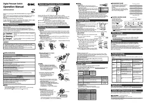
Digital Pressure SwitchOperation ManualZSE40A(F)/ISE40AThank you for purchasing the SMC ZSE40A(F)/ISE40A Series Digital Pressure Switch.Please read this manual carefully before operating the digital pressure switch and make sure you understand the digital pressure switch, its capabilities and limitations.Please keep this manual handy for future reference.To get information in detail for operating this product, refer to SMC website (URL ) or contact us.Indication light (Orange LED): Displays the switch operation condition.LCD display: Displays the current status of pressure, setting mode and error code.Four display modes can be selected to display always in red orgreen only, or changing from green to red, red to green according to the output status.button (UP): Selects the mode or increases the ON/OFF set value.Press this button to change to the peak display mode.button (DOWN): Selects the mode or decreases the ON/OFF set value.Press this button to change to the bottom display mode.button (SET): Press this button to change to either mode and to set a value.These safety instructions are intended to prevent hazardous situations and/or equipment damage.These instructions indicate the level of potential hazard with the labels of"Caution", " Warning" or "Danger". They are all important notes for safety and must be followed in addition to International standards (ISO/IEC), Japan Industrial Standards (JIS) and other safety regulations.OperatorInstallationMountingMount the optional bracket and panel mount adapter to the pressure switch.When the pressure switch is to be mounted in a place where water and dust splashes occur, insert a tube into the air-relieving port of the pressure switch.(Refer to "Tube attachment")Mounting with bracketFix the bracket to the pressure switch with the set screws M3x5L (2 pcs.) or M4x5L (2 pcs.) supplied.Apply a tightening torque of 0.5 to 0.7 Nm for the M3 set screws or 1.4 to 1.6 Nm for the M4 set screws .WiringConnection Make connection after turning the power e a separate route when connecting the wire ofthe Pressure switch.Malfunction stemming from noise may occur if the wire is installed in the same route as that of power or high-voltage cable.Be sure to ground terminal FG when using a commerically available switch-mode power supply.When the switch-mode power supply is connected to the Pressure switch,switching noise wil be superimposed and product specification can no longer be met. This can be prevented by inserting a noise filter, such as a line noise filter and ferrite core, between the switch-mode power supply and the Pressure switch, or by using a series power supply instead of the switch-mode power supply.Names of individual partsSet ON point and OFF point of the Pressure switch.Operation When the pressure exceeds a set value, the Pressure switch will be turned on.When the pressure falls below the set value by the amount of hysteresis or more, the Pressure switch will be turned off.The default setting of the output set value is the central value between the atmospheric pressure and the upper limit of the rated pressure range. If theoperation shown the right does not cause any problem, keep this operation setting.Switch ONP_1H_1Time [s]P r e s s u r e [P a ]<How to operate>button once in measurement mode.(2)[P_1] or [n_1] and set value are displayed in turn.Normal output Reversed outputbutton once to increase by one figure, and press it continuously to keep button once to decrease by one button to finish the setting of OUT1.[ Window comparator mode ]The Pressure switch turns on within a set pressure range (from P1L to P1H)during window comparator mode. Set P1L (switch lower limit) and P1H (switch At the time of shipment, the following settings are provided.If the setting is acceptable, keep it for use.To change setting, refer to SMC website (URL ) to get information in detail or contact us.[F 0] Unit conversion functionSame setting as [F 1] OUT1.At the output mode, Error detection mode can be selected.Display color is linked to the setting of OUT1, and can not be selected.Other parameter settingMeasurement modeThe measurement mode is the condition where the pressure is detected and indicated, and the switch function is operating.This is the basic mode, and other modes should be selected for setting change and other function setting changes.Function selection modeMeasurement modePeak/Bottom hold value indication Zero clear Key lockTo set each function the above in detail, refer to SMC website (URL ) to get information in detail or contact us.MaintenanceHow to reset the product after power cut or forcible de-energizing The setting of the product will be retained as it was before a power cut or de-energizing.The output condition is also basically recovered to that before a power cut or de-energizing, but may change depending on the operating environment.Therefore, check the safety of the whole facility before operating the product. If the facility is using accurate control, wait until the pressure switch has warmed up.(About 10 to 15 minutes)∗:Some functions are not available depending on part number. All functions are displayed with[F ] and followed with function description. If a function is not available for specified type, the function is displayed as [---].TroubleshootingError indication functionThis function is to display error location and content when a problem or an error occurs.SpecificationRefer to the product catalogue or SMC website (URL ) to get information about product specifications in detail.Outline with Dimensions (in mm)Refer to the product catalogue or SMC website (URL ) to get information about outline dimensions in detail.Akihabara UDX 15F, 4-14-1, Sotokanda, Chiyoda-ku, Tokyo 101-0021, JAPAN Phone: +81 3-5207-8249 Fax: +81 3-5298-5362URL Note: Specifications are subject to change without prior notice and any obligation on the part of the manufacturer.© 2009 SMC Corporation All Rights Reserved•Bracket A or D(Model: ZS-24-A/ZS-24-D)•Bracket B (Model: ZS-24-B)[01/N01 type][W1/WF1 type]button for 2[F 0]. Select to display the function setting to be changed, [F ].button for 2selection mode to return tomeasurement mode.。
使用说明书SMC过滤器 (FGE 系列)FGESA-10(20) , FGELA-10(20)FGESB-10(20) , FGELB-10(20)FGESC-10(20) , FGELC-10(20)SMC株式会社目 录● 安全上的注意・・・・・・・・・・・・・・・・P2 ● 零件名称及功能・・・・・・・・・・・・・・・P3 ● 系统设计,设置,配管・・・・・・・・・・・・・P4 ● 操作・・・・・・・・・・・・・・・・・・・・P4 ● 产品规格・・・・・・・・・・・・・・・・・・P4 ● 滤芯更换和拆卸 ・・・・・・・・・・・・・・P5 ● 本公司主要营业所一览・・・・・・・・・・・・P8FGES,L系列安全上的注意这里所指的注意事项,记载了FGES,FGEL系列产品应如何安全正确的使用,以防止对您及他人造成损伤。
所有与安全相关的重要内容以及其他安全规则,都必须严格遵守。
注意:误操作时,可能造成人及设备的损伤。
警告:误操作时,可能造成人的死亡或重伤。
警告:误操作时,可能会发生漏液或上盖飞出等危险事故。
请有足够知识和经验系统设计者来判断元件的选型是否合适。
使用条件范围操作上的注意①使用压力不要使用超出范围的压力。
②使用温度不要使用超出范围的温度。
③使用流体・禁止使用于气体。
・不要使用于腐蚀性液体。
・不要使用于会引起密封圈,O形圈以及滤芯膨胀或劣化的流体。
④使用环境・不要在有腐蚀性的环境下使用。
・不要在有振动和物体冲击的环境下使用。
①加压状态下禁止松开V形带。
②V形带正确地安装在指定的位置上。
(请参照第7页)③发生膨胀或劣化等异常的O形圈,请进行更换。
O形圈的更换,请在使用后1年以内,或者有漏液发生时进行。
(更换用O形圈:参照3页表1)④泵起动时,请务必将上部的空气排气口打开,进行排气。
⑤请不要使用变形或螺纹破损的V形带。
(更换用V形带:参照3页表1)注意:为防止滤芯破损,保障滤芯的过滤性能及保养点检的可作业性,请务必遵守以下注意事项。
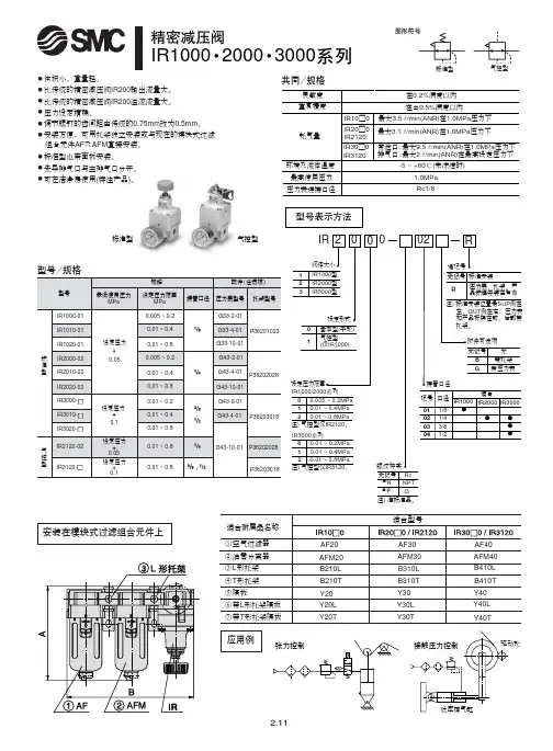
!"IR1000 2000 3000常泄口: 最大9.5l /min(ANR)在1.0MPa 压力下排气口: 最大2 l /min(ANR)在最高设定压力下最大3.5 l /min(ANR)在1.0MPa 压力下最大3.1 l /min(ANR)在1.0MPa 压力下标准型气控型应用例安装在模块式过滤组合元件上灵敏度重复精度耗气量环境及流体温度在0.2%满度以内在±0.5%满度以内-5 ~ +60℃(未冻结时)IR10□0IR20□0IR2120IR30□0IR3120最高使用压力压力表连接口径1.0MPa Rc1/8共同/规格无记号注)N 注)F NPT G Rc 注) 准标准品。
标准型气控型●体积小,重量轻。
● 比传统的精密减压阀IR200输出流量大。
● 比传统的精密减压阀IR200溢流流量大。
● 压力设定精确。
● 调节螺钉的齿间距由传统的0.75mm 改为0.5mm 。
● 安装方便,可用托架独立安装或与现在的模块式过滤组合元件AF 及AFM 直接安装。
●标准型也带面板安装。
● 先导排气口与主排气口分开。
● 可在洁净房使用(特注产品)。
!"#IR20□0-02!"IRV 000真空压力(负压)现可以任意调节!■灵敏度高■重复精度高■调节范围宽用途例工件的吸着真空测试检查装置真空泵电磁阀过滤器吸盘工件电磁阀真空泵真空罐过滤器吸盘工件真空泵电磁阀工件过滤器电磁阀压力转换器真空泵真空罐差压感应器电磁阀过滤器单一压力的情况不同压力的情况真空罐IRV IRVIRVIRV工件型号表示方法记号01020304口径1/81/43/81/2适合系列IRV1000IRV 23000IRV3000压力表接管口径接管口径大气接管口径压力表接管口径(吸盘侧)(真空泵侧)接管口径大气2-Rc1/82-Rc1/82-1/4·3/8,1/2Rc1/22-1/82-1/4。
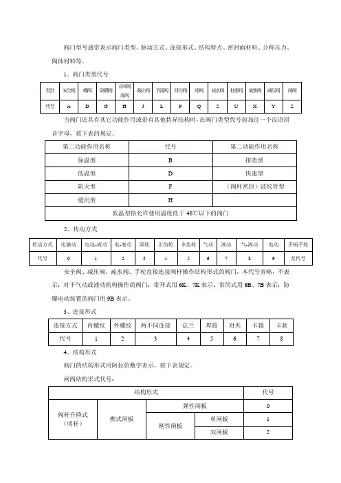
阀门型号通常表示阀门类型、驱动方式、连接形式、结构特点、密封面材料、公称压力、阀体材料等。
1、阀门类型代号
当阀门还具有其它功能作用或带有其他特异结构时,在阀门类型代号前加注一个汉语拼音字母,按下表的规定。
2、传动方式
安全阀、减压阀、疏水阀、手轮直接连接阀杆操作结构形式的阀门,本代号省略,不表示;对于气动或液动机构操作的阀门:常开式用6K、7K表示;常闭式用6B、7B表示;防爆电动装置的阀门用9B表示。
3、连接形式
4、结构形式
阀门的结构形式用阿拉伯数字表示,按下表规定。
闸阀结构形式代号:
截止阀、节流阀和柱塞阀结构形式代号
球阀结构形式代号
蝶阀结构形式代号
隔膜阀结构形式代号
旋塞阀结构形式代号
止回阀结构形式代号
安全阀结构形式代号
减压阀结构形式代号
蒸汽疏水阀结构形式代号
排污阀结构形式代号
五、密封副材料
六、公称压力数值用阿拉伯数字直接表示,它是MPa的10倍。
七、阀体材料
PL50-1.6RF (其中PL是指板式平焊钢制管法兰50是指公称通径DN50 1.6是指公称压力PN1.6 RF是指法兰密封面型式是突面)。
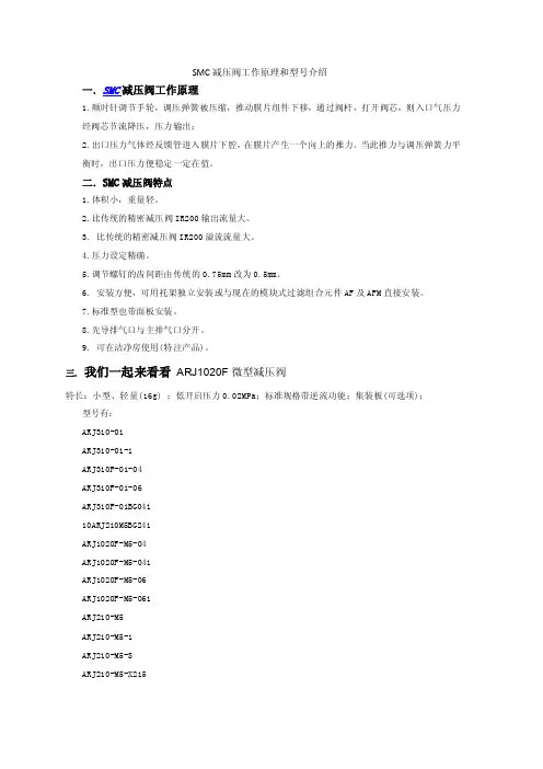
SMC减压阀工作原理和型号介绍
一.SMC减压阀工作原理
1.顺时针调节手轮,调压弹簧被压缩,推动膜片组件下移,通过阀杆,打开阀芯,则入口气压力
经阀芯节流降压,压力输出;
2.出口压力气体经反馈管进入膜片下腔,在膜片产生一个向上的推力。
当此推力与调压弹簧力平
衡时,出口压力便稳定一定在值。
二.SMC减压阀特点
1.体积小,重量轻。
2.比传统的精密减压阀IR200输出流量大。
3. 比传统的精密减压阀IR200溢流流量大。
4.压力设定精确。
5.调节螺钉的齿间距由传统的0.75mm改为0.5mm。
6. 安装方便,可用托架独立安装或与现在的模块式过滤组合元件AF及AFM直接安装。
7.标准型也带面板安装。
8.先导排气口与主排气口分开。
9. 可在洁净房使用(特注产品)。
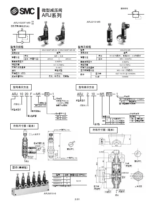
三.我们一起来看看ARJ1020F微型减压阀
特长:小型、轻量(16g) ;低开启压力0.02MPa;标准规格带逆流功能;集装板(可选项);
型号有:
ARJ310-01
ARJ310-01-1
ARJ310F-01-04
ARJ310F-01-06
ARJ310F-01BG041
10ARJ210M5BG241
ARJ1020F-M5-04
ARJ1020F-M5-041
ARJ1020F-M5-06
ARJ1020F-M5-061
ARJ210-M5
ARJ210-M5-1
ARJ210-M5-S
ARJ210-M5-X215
ARJM10-10 ARJM10-4。
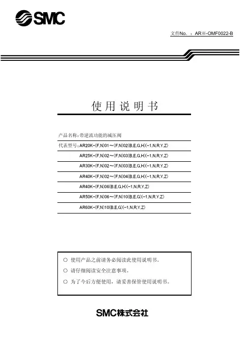
文件No.:AR ※-OMF0022-B○ 使用产品之前请务必阅读此使用说明书。
○ 请仔细阅读安全注意事项。
○ 为了今后方便使用,请妥善保管使用说明书。
AR25K-(F,N)02~(F,N)03(B,E,G,H)(-1,N,R,Y,Z)产品名称:带逆流功能的减压阀代表型号:AR20K-(F,N)01~(F,N)02(B,E,G,H)(-1,N,R,Y,Z)AR40K-(F,N)02~(F,N)04(B,E,G,H)(-1,N,R,Y,Z)AR40K-(F,N)06(B,E,G,H)(-1,N,R,Y,Z)使 用 说 明 书AR50K-(F,N)06~(F,N)10(B,E,G)(-1,N,R,Y,Z)AR30K-(F,N)02~(F,N)03(B,E,G,H)(-1,N,R,Y,Z)AR60K-(F,N)10(B,E,G)(-1,N,R,Y,Z)目录页1、安全注意事项 1—32、用途43、规格44、型号表示方法45、故障及对策56、构造图/零件清单67、更换操作要领 7—98、分解图 10—119、外观尺寸12SMC(中国)有限公司地址:北京市经济技术开发区兴盛街甲2号 (100176)网址:2、用途 本产品用于气路中的压力控制。
内部设有逆流功能,当入口压力与出口压力相比,下降到规定量时,出口压力将向入口侧开放。
3、型号AR20K AR25K AR30K AR40K AR40K-06AR50KAR60K 管连接口径1/8、1/41/4、3/81/4、3/81/4、3/8、1/23/43/4、11使用流体保证耐压力最高使用压力注1)设定压力范围注2)压力表连接口径环境温度及使用流体温度构造质量0.26kg 0.21kg 0.29kg 0.44kg0.47kg 1.17kg 1.22kg注1) 使1次侧压力比设定压力高0.05MPa以上。
注2) 带四方形埋入式压力计时,没有压力计连接用螺钉。
4、型号表示方法型式空气1.5MPa 1.0MPa -5~60℃(无冻结)溢流型0.05~0.85MPa1/81/4设定压力+0.05MPa{只在溢流流量为0.1L/min (ANR) 时}溢流压力5.故障与对策区分现象压力不能调整1.流向错误。
1.概述SMC系列阀门电动装置是Limitorque阀门电动装置的主体,其技术是Limitorque技术的精华和集中体现。
由SMC系列可派生出若干形式的电动装置产品。
由于被驱动控制的阀门形式不同,Limitorque电动装置亦分为两种基本形式:第一种用于控制多回转阀门,如闸阀、截止阀、隔膜阀等。
第二种用于控制部分回转阀门,如球阀、蝶阀、旋塞阀等。
在部分回转电动装置产品中通常又细分为组合式(亦称叠加式)和独立式(亦称整体式)两种结构型式。
组合式是一级多回转产品和二级减速器的组合,独立式则是将整个减速系统设置在同一个主箱体中。
实践证明,独立式部分回转电动装置是一个经济型产品,它虽然体积相对小,但组合式的很多优势它并不具备。
所以在控制性能要求较高的工况条件多首选组合式产品。
Limitorque电动装置属于高档次的产品,因而其部分回转产品多为组合式。
实际上,在多回转电动装置结构上亦有组合式的情况,最典型的是SMC系列与BA系列减速器的组合,这些会在下面详细介绍。
1.1SNC系列多回转阀门电动装置:SMC系列做为一种多回转产品,它所控制的阀门工作时阀瓣做直线运动,如最常见的楔式闸阀,平板闸阀、截止阀等等。
多回转电动装置的工作特点是:输出轴(亦称驱动空心轴)工作时做多圈回转并驱动阀杆螺母或阀杆旋转,进而带动阀瓣做上下往返运动完成阀门的启闭。
(设阀杆轴线垂至于地面)SMC系列电动装置的输出轴为上下贯通,以保证明杆阀门的阀杆通过或进入。
电动装置单行程旋转的圈数取决于阀门的口径和阀杆丝杆部分的参数。
多回转阀门可由电动装置完成行程控制关闭或转矩控制关闭,也可将两种控制形式配合使用。
SMC系列产品具有可靠的行程、转矩控制性能。
从Limitorque的直译“ 转矩限制”,我们可见输出转矩值是一个产品的重要参数。
根据输出转矩的不同又形成了产品的不同结构型式及尺寸,即不同的机座号。
SMC系列多回转电动装置共有9个机座号,它们是SMC-04~SMC~5。
Series AW20~40Filter -RegulatorHow To OrderAW 30N 03D8Z -X48——Filter -Regulator Note:Other sizes,thread forms,options,etc.may be possible,please contact SMC for availability.With External Epoxy Coating,Stainless Fasteners Name Plate,Caution Plate On Bowl in psi,˚FNPT ThreadsBody SizeSymbol 203040Size 1/83/81/2Port SizeSymbol 020304Port Size 1/43/81/2Applicable Body Size203040SpecificationsBody sizeOperating specifications Port sizeAuto drain port Bowl type Body material Bowl materialBody,Bowl surface treatment BonnetManual drain (AF ,AW)External screwsIndividual mounting brackets Panel mount nutSight glass hardware203040Same as standard -see catalog ES40-42D or NC160A1/4”NPT N/A Metal 1/4”NPT Metal with sight gaugeDie cast aluminum Die cast aluminum Epoxy resin coatingPolyacetal POMStainless steel 410Epoxy coated steelPOMStainless steel 3043/8”NPT1/2”NPT BowlSymbol 28DescriptionMetal BowlMetal Bowl With Sight GlassApplicable Body Size 2030,40Accessories Symbol Nil B*C D H*Description None Mounting Bracket Float Auto Drain (N.C.)Float Auto Drain (N.O.)Panel Mount NutApplicable Body SizeAll All 30,4030,40AllAW30AW40A NPT 3/8NPT 1/2Dimensions Model Port Size C NPT 1/8NPT 1/4Gauge PortD 5370DD 34.541E 3038F 83(max.86)88(max.92)H3.51.5J 239(max.242)276(max.280)K 5975L 4150Q 4654S 6.58.5U 4054T 810.5V 5370W 2.32.3X M38X 1.5M42X 1.5Y 3135.5Z 77AA 1921CC 38.542.5AW20AW30AW40A NPT 1/4NPT 3/8NPT 1/2Dimensions Model Port Size C NPT 1/8NPT 1/8NPT 1/4Gauge PortD405370DD —34.541E —3038F 70(max.73)83(max.86)88(max.92)H 53.51.5J 157(max.160)218(max.221)255(max.259)K 525975L 304150Q 444654S 5.46.58.5U 344054T 15.4810.5AW20AW30AW40Mounting Bracket Kit(Optional)AW20P-270AS-X480AR30P-270AS-X480AR40P-270AS-X480Model V 555370W 2.32.32.3X M28X 1M38X 1.5M42X 1.5Y 303135.5Z 677AA 141921CC 28.538.542.5Panel Mounting Nut(Optional)AR20P-260S AR30P-260S AR40P-260SAuto DrainStandardAccessoriesDimensions -Refer to drawings on page 7mmmm *Note:Bracket and/or panel mount nut are not assembled and are suppliedloose at time of shipment.C o u r t e s y o f C M A /F l o d y n e /H y d r a d y n e ▪ M o t i o n C o n t r o l ▪ H y d r a u l i c ▪ P n e u m a t i c ▪ E l e c t r i c a l ▪ M e c h a n i c a l ▪ (800) 426-5480 ▪ w w w .c m a f h .c o mSeries AW20~40Filter -RegulatorStandard(ManualDrain)2-Bracket and (Optional )With AutoDrain2-Bracket and (Optional)Bowl Detail EE(AW20)Note:Sight glass not applicable to AW20.C o u r t e s y o f C M A /F l o d y n e /H y d r a d y n e ▪ M o t i o n C o n t r o l ▪ H y d r a u l i c ▪ P n e u m a t i c ▪ E l e c t r i c a l ▪ M e c h a n i c a l ▪ (800) 426-5480 ▪ w w w .c m a f h .c o m。
SMC减压阀的选型原则SMC减压阀(Pressure Relief Valve)是一种用于控制系统中压力的安全装置,能够通过调整流体的排放来维持系统压力在设定范围内。
选型准则是指在选择合适的SMC减压阀时需要考虑的一些关键因素。
以下是一些选型原则,以帮助您选择适用的SMC减压阀。
1.工作压力范围:首先需要确定系统的工作压力范围。
SMC减压阀的工作压力范围应该大于系统的最高工作压力,同时要确保最低工作压力不低于系统所需的最小工作压力。
2.流量要求:根据系统的流量要求选择合适的SMC减压阀。
减压阀的流量能力应该能够满足系统的最大流量需求,同时要考虑到系统的稳定性和效率,通常建议选择流量略大于实际需求的减压阀。
3.环境条件:考虑到SMC减压阀将运行的环境条件,包括温度、介质的物性以及工作环境的腐蚀性等。
这些条件将影响减压阀的材料选择以及密封性能。
4.减压精度:根据系统的要求选择合适的减压精度。
减压阀的减压精度决定了系统的压力控制能力,精度要求较高的系统可能需要更精确的减压阀。
5.设备安全认证:确保选择的SMC减压阀符合相关的安全认证标准,例如CE、UL、ISO等。
这些认证标准代表了减压阀的质量和安全性能。
6.价格和可靠性:考虑到选型的成本和可靠性。
通常情况下,较高质量和可靠性的减压阀价格也相对较高,但是这也能够降低系统维修和更换的成本。
7.适用性:根据实际应用场景选择适用的减压阀。
不同的应用场景可能有不同的要求,例如低温环境、高温环境、高压环境等,需要选择适合的减压阀。
8.维护和保养:选择容易维护和保养的减压阀,以降低维护成本和减少停机时间。
9.厂家支持:选择有良好售后服务和技术支持的减压阀厂家,以确保在使用过程中能够及时解决问题。
选用合适的SMC减压阀是确保系统安全稳定运行的重要步骤。
通过考虑上述原则,可以选择到适合系统要求、质量可靠并符合相关标准的减压阀。
SMC减压阀的选型原则SMC是一家全球性的自动化控制设备生产厂家,其减压阀的应用范围广泛,涵盖了工业、农业、医疗、物流等各个领域。
然而,不同领域的应用需求也有所不同,因此,在选型减压阀时需要遵循一些基本原则。
1. 流量与压差减压阀的主要作用是将高压气体或流体减压到设定的压力范围内,因此,在选型减压阀时,需要首先了解其设计的可调整范围。
一般来说,减压阀的调整范围越大,则其适用范围也越广。
此外,需要注意的是,选型减压阀时需要考虑所需的流量与压差。
流量与压差是决定减压阀工作稳定性与准确性的两个关键因素。
如果需要处理的气体或流体流量较大,那么就需要选用具有较大流量和调整范围的减压阀。
此外,对于高流量和高压差环境,需要选用高耐压、高流量的减压阀,以确保其可靠性和稳定性。
2. 工作环境在选择SMC减压阀时,需要考虑应用环境的特点。
例如,如果工作环境是极低温或极高温的,则需要选择相应的耐温型减压阀。
而对于在危险环境下使用的减压阀,则需要具备防爆、防腐等特殊的功能,并且需要符合相关的安全标准。
此外,工作环境的空间大小也是选择SMC减压阀的考虑因素之一。
如果工作空间有限,则需要选择紧凑型、方便安装和维护的减压阀。
3. 工艺要求不同行业、不同工艺对减压阀的要求也有所不同。
例如,食品、制药行业对产品的材质、清洁度和卫生标准有着更高的要求。
满足这些要求的减压阀需要选用符合相关标准的材料,并且需要具备良好的清洁性和卫生性。
另外,对于一些精密工艺或需要高精度的工艺,减压阀的调节精度、稳定性以及响应速度也需要满足更高的要求。
4. 品牌和质量保证品牌和质量保证是选择SMC减压阀的重要考虑因素之一。
作为全球自动化控制设备领域的领导品牌,SMC拥有较高的生产技术和品质控制标准,并且提供全面的售后服务。
在选择减压阀时,应该优先选择可靠性高、品质保证的品牌和型号。
5. 价格与性价比在选择SMC减压阀时,需要考虑其价格与性价比。
虽然品质保证和可靠性是选型减压阀时需要优先考虑的因素,但是对于一些预算受限的应用场景而言,也需要优先考虑性价比高的减压阀型号。
阀门ts新旧标准对比如下:
1.标准名称不同:新标准为《阀门技术条件》(GB/T 24925-2019);
旧标准为《阀门通用技术条件》(GB/T 12237-2007)。
2.适用范围不同:新标准适用于各种工业管道和民用自来水、燃
气、热力管道中的各种阀门;旧标准适用于工业管道中的各种阀门。
3.阀门种类分类不同:新标准将阀门种类分为截止阀、调节阀、
止回阀、安全阀、减压阀、排气阀、隔膜阀、球阀、蝶阀、旋塞阀、闸阀、电动阀、气动阀等13类;旧标准将阀门种类分为截止阀、调节阀、止回阀、安全阀、减压阀、排气阀、隔膜阀、球阀、蝶阀、旋塞阀、闸阀、电动阀等12类。
4.技术要求细化:新标准对阀门的各项技术要求更为细化,如对
材料、制造、尺寸、公称压力、密封性、耐腐蚀性、耐磨损性、耐高温性等方面均作出了更为详细的规定和要求。
5.检验与试验要求更严格:新标准对阀门的检验与试验要求更为
严格,如强度试验、密封试验、低温试验、耐腐蚀试验、耐磨损试验、耐高温试验等方面均作出了更为详细的规定和要求。
6.阀门标识更加完善:新标准对阀门的标识作出了更为详细的规
定和要求,如要求在阀门上标明产品名称、公称通径、公称压力、阀门材质、制造厂家、生产批号、制造日期等信息。
以上是阀门TS新旧标准的主要对比,新标准相比于旧标准在技术要求、试验要求、检验要求和标识要求等方面都有所提高和改进。
SMC过滤减压阀的选用原则资料参数SMC过滤减压阀按结构形式可分为偏置板式、垂直板式、斜板式和杠杆式。
按密封形式可分为软密封型和硬密封型两种。
软密封型一般采用橡胶环密封,硬密封型通常采用金属环密封。
SMC过滤减压阀结构原理:SMC过滤减压阀通常由角行程电动执行机构(0~90°部分回转)和SMC过滤减压阀整体通过机械连接,经过安装调试后共同组成。
根据动作模式分类有:开关型和调节型。
开关型是直接接通电源(AC220V或其他电源等级的电源)通过开关正、反导向来完成开关动作。
调节型是以AC220V电源作为动力,接收工业自动化控制系统预设的参数值4~20mA(0~5等弱电控制)信号来完成调节动作。
SMC过滤减压阀应用场合:SMC过滤减压阀适用于流量调节。
由于SMC过滤减压阀在管路中的压力损失比较大,还应考虑关闭时蝶板承受管道介质压力的坚固性。
此外,还必须考虑在高温下弹性阀座材料所承受工作温度的限制。
SMC过滤减压阀的结构长度和总体高度较小,开启和关闭速度快,且具有良好的流体控制特性,SMC过滤减压阀的结构原理适合制作大口径阀门。
当要求蝶阀作控制流量使用时,重要的是正确选择蝶阀的尺寸和类型,使之能恰当地、有效地工作。
电动调节蝶阀适用于要求达到完全密封、气体试验泄漏为零、寿命要求较高、工作温度在-10度~150度的淡水、污水、海水、盐水、蒸汽、天然气、食品、药品、油品和各种酸碱及其他管路上。
(1)由于SMC过滤减压阀压力损失比较大.故适用于压力损失要求不严的管路系统中。
(2)由于SMC过滤减压阀可以用作流量调节,故在需要进行流量调节的管路中宜于选用。
(3)由于SMC过滤减压阀的结构和密封材料的限制,不宜用于高温、高压的管路系统。
一般工作温度在300摄氏度以下,公称压力在PN40以下。
(4)由于SMC过滤减压阀结构长度比较短,且又可以做成大口径,故在结构长度要求短的场合或是大口径阀门(如DN1000以上),宜选用SMC过滤减压阀。
旧款新款(-A)对比说明型号AW40-N04BG AW40-N04BG-A
名称过滤减压阀过滤减压阀
品牌SMC SMC
图片新款采用透明杯体,可360°目视杯本内冷凝水状态。
主体大小4040相同
螺纹种类NPT NPT相同
接管口径1/2"1/2"相同
托架含有含有相同
压力表圆形(带限位指示器)圆形(带限位指示器)相同
排水方式手动手动相同
过滤精度5um5um相同
贮留量8cm38cm3相同
阀体尺寸
A7070相同
B239247.1总体高度尺寸增大
H7672距压力表前端尺寸减小G10540维护空间减小
托架尺寸
M5050相同
P5454相同
T7070相同
N5438中心距减小
S10.526.5腰孔扩大
关于SMC过滤减压阀AW40-N04BG新旧款区别技术说明
安装孔示意图新款安装孔为腰型孔,包含了老款安装孔位置
Q8.58.5相同小结:新款性能优于老款,托架安装孔扩大为腰型孔,替换安装不受影响。