Hall 5e TB Ch14
- 格式:rtf
- 大小:127.06 KB
- 文档页数:13

la u n a ms 'r e n w o THE SINGER'S ULTIMATE CHOICEUHF-5805Features:• 4 mic outputs• 4 rechargeable wireless handheld mics included • 2 dual microphone chargers• Individual Volume controls for precise vocal bala • Individual Volume controls for precise vocal balancing • 4 independent field-replaceable Modules• Rugged 1 RU metal receiver chassis • Dimensions 19” (W) x 8.2” (D) x 1.8” (H)4-Channel Rechargeable Wireless Microphone System• Interference-resistant UHF Band operation from 614 MHZ - 649 MHzTable of contentsSafety instructions (2)FCC information (3)Welcome (4)Listening for a lifetime (5)Specifications (6)Microphone basics (7)Before getting started (8)Mounting (9)Getting connected (10)Maintenance procedures (11)Charging the Microphones (12)Front and rear panel descriptions and functions (13)UHF-5805 & stage monitor/P.A. loudspeakers (14)Operations (14)Troubleshooting (15)��������������������CAUTION: To reduce the risk of electric shock, do not remove cover (or back). Nouser-serviceable parts inside. Only refer servicing to qualified service personnel.�������To reduce the risk of fire or electric shock, do not expose this unit to rain or moisture.��������������������������������The lightning flash & arrowheadsymbol, within an equilateral triangle, is intended to alert you to the presence of danger.The exclamation point within anequilateral triangle is intended to alert you to the presence of importantoperating and servicing instructions.�������������������� - All the safety and operating instructions should be read before the appliance is operated.���������������������� - The safety and operating instructions should be retained for future reference.���������������� - All warnings on the appliance and in the operating instructions should be adhered to.���������������������� - All operating and use instructions should be followed.�������������� - Do not use attachments notrecommended by the product manufacturer as they may cause hazards.��������������������� - Do not use this unit near water. For example, near a bathtub or in a wet basement and the like.������������������� - The appliance should be used only with a cart or stand that is recommended by the manufacturer.���� An appliance and cart combination should be moved with care. Quick stops, excessive force, and uneven surfaces may cause an overturn.�������������� - The appliance should be situated so its location does not interfere with its proper ventilation. For example, the appliance should not be situated on a bed, sofa, rug, or similar surface that may block the ventilation slots.������� - The appliance should be situated away from heat sources such as radiators, heat registers, stoves, or other appliances (including amplifiers) that produce heat.����������������� - The appliance should beconnected to a power supply only of the type described in the operating instructions or as marked on the appliance.����������������������������� - Precautions should be taken so that the grounding or polarization means of an appliance is not defeated.������������������������� - Power-supply cordsshould be routed so that they are not likely to be walked on or pinched by items placed upon or against them, paying particular attention to cords at plugs,convenience receptacles, and the point where they exit from the appliance.������������ - Unplug this unit from the wall outlet before cleaning. Do not use liquid cleaners or aerosol cleaners. Use a damp cloth for cleaning.��������������� - An outdoor antenna should be located away from power lines.������������������ - The power cord of the appliance should be unplugged from the outlet when left unused for a long period of time.��������������������������� - Care should be taken so that objects do not fall and liquids are not spilled into the enclosure through openings.���������������������������� - The appliance should be serviced by qualified service personnel when:A. The power supply cord or plug has been damaged; or B. Objects have fallen into the appliance; or C. The appliance has been exposed to rain; orD. The appliance does not appear to operate normally or exhibits a marked change in performance; orE. The appliance has been dropped, or the enclosure damaged.������������� - The user should not attempt to service the appliance beyond that described in the operating instructions. All other servicing should be referred to qualified service personnel.������To CATV system installer's (U.S.A.): This reminder is provided to call the CATV system installer's attention to Article 820-40 of the NEC that provides guidelines for proper grounding and, in particular, specifies that the cable ground shall be connected as close to the point of cable entry as practical.SAFETY INSTRUCTIONS1. IMPORTANT NOTICE: DO NOT MODIFY THIS UNIT!: This product, when installed as indicated in the instructions contained in this manual, meets FCCrequirements. Modifications not expressly approved by Vocopro may void your authority, granted by the FCC, to use this product.2. IMPORTANT: When connecting this product to accessories and/or another product use only high quality shielded cables. Cable(s) supplied with this product MUST be used. Follow all installation instructions. Failure to follow instructions could void your FCC authorization to use this product in the U.S.A.3. NOTE: This product has been tested and found to comply with the requirements listed in FCC Regulations, Part 15 for Class "B" digital devices. Compliance with these requirements provides a reasonable level of assurances that your use of this product in a residential environment will not result in harmful interference with other electronic devices. This equipment generates/uses radio frequencies and, if not installed and used according to the instructions found in the owner's manual, may cause interference harmful to the operation of other electronic devices. Compliance with FCC regulations does not guarantee that interference will not occur in all installations. If this product is found to be the source of interference, which can be determined by turning the unit "Off" and "On", please try to eliminate the problem by using one of the following measures:Relocate either this product or the device that is being affected by the interference.Use power outlets that are on different branch (circuit breaker or fuse) circuits or install AC line filter(s).In the case of radio or TV interference,relocate/reorient the antenna. If the antenna lead-in is 300-ohm ribbon lead, change the lead-in to coaxial type cable.If these corrective measures do not produce satisfactory results, please contact your local retailer authorized to distribute Vocopro products. If you can not locate the appropriate retailer, please contact Vocopro, 1728 Curtiss Court, La Verne, CA 91750.1. To ensure the finest performance, please read this manual carefully. Keep it in a safe place for future reference.2. Install your unit in a cool, dry, clean place - away from windows, heat sources, and too much vibration, dust, moisture or cold. Avoid sources of hum (transformers, v motors). To prevent fire or electrical shock, do not expose to rain and water.3. Do not operate the unit upside-down.4. Never open the cabinet. If a foreign object drops into the set, contact your dealer.5. Place the unit in a location with adequate air circulation. Do not interfere with its proper ventilation; this will cause the internal temperature to rise and may result in a failure.6. Do not use force on switches, knobs or cords. When moving the unit, first turn the unit off. Then gently disconnect the power plug and the cords connecting to other equipment. Never pull the cord itself.7. Do not attempt to clean the unit with chemical solvents: this might damage the finish. Use a clean, dry cloth.8. Be sure to read the "Troubleshooting" section on common operating errors before concluding that your unit is faulty.9. This unit consumes a fair amount of power even when the power switch is turned off. We recommend that you unplug the power cord from the wall outlet if the unit is not going to be used for a long time. This will save electricity and help prevent fire hazards. To disconnect the cord, pull it out by grasping the plug. Never pull the cord itself.10. To prevent lightning damage, pull out the power cord and remove the antenna cable during an electrical storm. 11. The general digital signals may interfere with other equipment such as tuners or receivers. Move the system farther away from such equipment if interference is observed.NOTE:Please check the copyright laws in your country beforerecording from records, compact discs, radio, etc.Recording of copyrighted material may infringecopyright laws.CAUTIONThe apparatus is not disconnected from the AC power source so long as it is connected to the wall outlet, even if the apparatus itself is turned off. To fully insure that the apparatus is indeed fully void if residual power, leave unit disconnected from the AC outlet for at least fifteen seconds. ����������������������������������������������������������������������������������Be sure to position the voltage selector to match the voltage of your local power lines before installing the unit.240V120VFCC INFORMATION (U.S.A.)Welcome...And Thank you for purchasing the UHF-5805from VocoPro, your ultimate choice in Karaoke entertainment! With years of experience in the music entertainment business, VocoPro is a leading manufacturer of Karaoke equipment, and has been providing patrons of bars, churches, schools, clubs and individual consumers the opportunity to sound like a star with full-scale club models, in-home systems and mobile units. All our products offer solid performance and sound reliability, and to reinforce our commitment to customer satisfaction, we have customer service and technical support professionals ready to assist you with your needs. We have provided some contact information for you below.VocoPro1728 Curtiss CourtLa Verne, CA 91750Toll Free: 800-678-5348TEL: 909-593-8893FAX: 909-593-8890VocoPro Company Email DirectoryCustomer Service & General Information****************Tech Support***********************Remember Our WebsiteBe sure to visit the VocoPro website for the latest information on new products, packages and promos. And while you're there don't forget to check out our Club VocoPro for Karaoke news and events, chat rooms, club directories and evena KJ Service directory!We look forward to hearing you sound like a PRO, with VocoPro, your ultimate choice in Karaoke entertainment.FOR YOUR RECORDSPlease record the model number and serial number below, for easy reference, in case of loss or theft. These numbers are located on the rear panel of the unit. Space is also provided for other relevant informationModel NumberSerial NumberDate of PurchasePlace of PurchaseSelecting fine audio equipment such as the unit you’ve just purchased is only the start of your musical enjoyment. Now it’s time to consider how you can maximize the fun and excitement your equipment offers. VocoPro and the Electronic Industries Association’s Consumer Electronics Group want you to get the most out of your equipment by playing it at a safe level. One that lets the sound come through loud and clear without annoying blaring or distortion and, most importantly, without affecting your sensitive hearing.Sound can be deceiving. Over time your hearing “comfort level” adapts to a higher volume of sound. So what sounds “normal” can actually be loud and harmful to your hearing. Guard against this by setting your equipment at a safe level BEFORE your hearing adapts.To establish a safe level:• Start your volume control at a low setting.• Slowly increase the sound until you can hear it comfortably and clearly, and withoutdistortion.Once you have established a comfortable sound level:• Set the dial and leave it there.• Pay attention to the different levels in various recordings.Taking a minute to do this now will help to prevent hearing damage or loss in the future. After all, we want you listening for a lifetime.Used wisely, your new sound equipment will provide a lifetime of fun and enjoyment. Since hearing damage from loud noise is often undetectable until it is too late, this manufacturer and the Electronic Industries Association’s Consumer Electronics Group recommend you avoid prolonged exposure to excessive noise. This list of sound levels is included for your protection.���������������������������Level������������ExampleQuiet library, Soft whispersLiving room, Refrigerator, Bedroom away from traffic Light traffic, Normal ConversationAir Conditioner at 20 ft., Sewing machineVacuum cleaner, Hair dryer, Noisy RestaurantAverage city traffic, Garbage disposals, Alarm clock at 2 ft.��������������������������������������������������������������Level��������������ExampleSubway, Motorcycle, Truck traffic, Lawn MowerGarbage truck, Chainsaw, Pneumatics drillRock band concert in front of speakersGunshot blast, Jet planeRocket launching pad-Information courtesy of the Deafness Research FoundationListening For A LifetimeSpecifi cationsReceiverCarrier Frequency Range: UHF 614~694MHzOscillation Mode: Quartz Controlled Fixed Frequency Stability: 10 PPMSensitivity: 1.6uV @ sinad =12dBMax. Deviation Range: 50HzS/N Ratio:>105dBT.H.D.: <0.5% @ 1kHzImage rejection: 85dB typicalSpurious Rejection: 75dB typicalFrequency Response: 40Hz~16kHzSquelch Control: dual-squelch circuitMax. Output Level: Balance: 0~400mV, Unbalance: 0~200mV Power Supply: External DC Power Supply, 0.7A, 12~15V DC Dimensions: 19”(L) x 8.2”(D) x 1.8”(H)Microphone basicsMicrophone PositionThe UHF-5805 is ideal for close-up vocals and can be held in the hand or mounted on a mic stand. The most common applications and placement techniques are listed below. Keep in mind that microphone technique is largely a matter of personal taste, and there is no one “correct” microphone position.Proximity EffectWhen the sound source is less than ¼ in. from the microphone, the microphone boosts bass frequencies (by 6 to 10 dB at 100 Hz), creating a warmer and richer bass sound than when farther away. This effect, known as proximity effect, happens only in unidirectional dynamic microphones like the UHF-5805.FeedbackFeedback occurs when the amplified sound from any loudspeaker reenters the sound system through any open microphone and is repeatedly amplified. Most commonly, feedback is caused by the following condi-tions: placing loudspeakers too close to microphones, having too many open active microphones, boosting tone controls indiscriminately (mainly treble) and performing in areas with high ratios of room surfaces that have hard and reflective surfaces such as glass, marble and wood. What to do if feedback occurs before the sound system is loud enough?• Request that the talker speak louder into the microphone.• Reduce the distance from the talker to the microphone. Each time this distance ishalved, the sound system output will increase by 6dB.• Reduce the number of open microphones.• Move the loudspeaker farther away from the microphone. Each time this distance isdoubled, the sound system output can be increased by 6dB.• Move the loudspeaker closer to the listener.• Use an equalizer/feedback reducer to cut the frequency bands in which the feedbackoccurs.Microphone Placement & Tone QualityLead & Backup VocalsLips should be less than 3” from or even touching the windscreen on an axis to the microphone. Doing this creates a robust sound, emphasizes bass and provides maximum isolation from other sources.SpeechWhen giving a speech or simply speaking, place the microphone 4” to 10” away from the mouth, just above nose height for a natural sound with reduced bass. You can also place the microphone 8” to 16” away from the mouth, slightly off to one side, for a more “distant” sound with highly reduced bass and minimal “s” sounds.Before getting startedBefore starting any installation procedures, it is recommend to completely unpack all the package contents. The original packaging should be kept in the event that re-shipping is needed. Upon unpacking the UHF-5805, you should have received the following items:•Custom Aluminum Travel Case (1)• UHF-5805 Receiver (1)• Handheld Microphones (4)• 3 ft. male/male ¼” cable (1)• 14V DC Main Unit power adapter (1), 9V DC Charger power adapter (2)• Dual Microphone Charger (2)9V9VUniversal Mic Charger Universal Mic Charger14VTo install the UHF-5805 to a 19” rack case, complete the steps below.1. Attach mounting brackets to the UHF-5805 via the supplied mounting screws.2. Align the UHF-5805 with the desired space in rack and slowly slide in, rear panel first.3. While aligned, use rack case screws (not included) in the order shown below to stabilize the UHF-5805 in its space, using the “X” rotation (numbered below) will ensure even tension and flush alignment.MountingNOTE: Depending on your rack case design, it may be neces-sary to allow for sufficient space for the antennas.NOTE: Do not tighten screws firmly until all screws are in place.����Maintenance proceduresRemoving the Field Replaceable ModulesEach of the 4 microphone modules on the UHF-5805 were designed in a way that allows them to slide out. This is a convenient feature if ever a module needs to be repaired or replaced.1. Remove the two screws that fasten the module to the front panel.2. To remove the module, simply slide the module out of the compartmentNOTE: It might be helpful to use a flat-head screwdriver to nudge the module out of its compartment.3. To re-insert, slide the module into compartment until it is completely secured. Secure the module withthe screws.The UHF-5805 comes with two dual chargers that let you charge all four microphones at the same time.Charging the MicrophonesIf the LED light on the microphone(s) does not light up when the microphone is turned on, this indicates that the microphone needs to be chargedTo charge:1. Place the microphone in the charger slot, the LED on the charger will be lit while the microphone is charging.2. When the LED on the charger turns off, the microphone is charged and can be removed.NOTE: For longest battery life, be sure to turn the microphones off when not in use.Reading the LED IndicatorsThe LEDs on the charger indicate the charging status. There are three states: blinking, on, and off.• Blinking - The power is connected to the charger but there are no microphones being charged • On - The microphone is being charged• Off - The microphone is completely charged and can be removed.Charger and Microphone Descriptions and Functions1. Microphone slots - Insert ne slots the microphones in these slots to charge2. Bodypack charger2. Body - pack charger Insert the optional rechargeable body pack in this slot to charge3. Microphone charge LED charge LED charge LE D in D - Indicate the - I indicators charging status of the microphones4. Bodypack charge LED in 4. Body - Indicates the charging status of the bodypack- I dicator - The color of this LED indicates the microphone’s charge level. Green means 5. Charge Indicator LED the charge is high, Orange means the charge is getting low and should be charged, and Red means the charge is very low and must be charged immediately.- Used to turn the microphone power ON and OFF . The mic power is ON when the 6. Power Switch switch is in the ON position and the power is OFF when the switch is in the OFF position.Charging the MicrophonesUniversal Mic Charger11562334NOTE:Make sure you are using the 9V power adapter for microphone chargersFront and rear panel descriptions and functions1.ANTEN ANTE NNA N - P NAS rovide both RF and AF signals.- Indicates whether the UHF-5805 is ON or OFF . When it is lit, the power is ON.2. POWER (LED) - Lights when RF signals are received from the microphone channels. - L 3. RF (LED) - 4. AF (LED)Lights when AF signals are received from the microphone channels.5. SQUELCH controls SQUELCH - Manual controls for controlling each microphone’s signal strength for bestcontrols performance. Turn clockwise to increase SQUELCH control and turn counter-clockwise to decreaseSQUELCH application.- Adjusts the individual VOLUME of the receiver’s 4 microphone channels.6. VOLUME controls - Contains the SQUELCH and VOLUME controls for each of the 4 wireless 7. MICROPHONE modules - C microphones. Each module can be easily removed individually. - Turns the UHF-5805 ON/OFF .8. POWER button - Main power jack for connection to an AC electrical outlet or power strip/surge 9. AC POWER connection - M protector. NOTE: Make sure you are connecting the 14V power adapter here.- This ¼” unbalanced output jack is for output connection to amplifiers, effects devices 10. MIXED OUTPUT or mixers. Both mic channels are output through this jack for mixed output. - These XLR unbalanced output jacks are for output connections to amplifiers, effects 11. XLR AUDIO OUTS devices or mixers. These are for separate mic channel connections with unmixed mic output.1567910113428UHF-5805 & stage monitor/p.a. loudspeakersIf you will be using the UHF-5805 with stage monitors and/or P.A. system, try the following:• Place the stage monitor directly behind the microphone.• Locate the P.A. loudspeakers so that they point away from the rear of the microphone. (With the speakers located in these positions, the possibility of feedback is greatly reduced).• Always check the stage setup before a performance to ensure optimum placement of microphone and monitors.IMPORTANT: Every wireless microphone installation is a unique situation, and can present a variety of prob-lems. Never attempt a live performance without first conducting a “walkthrough” test of the system in the performing area. If major changes (additional wireless systems or intercoms, relocation of scenery, etc.) have been made since the last walk-through test, check the wireless system again, as close to performance time as possible.P.A. Speakers Facing AwayFrom Rear of MicrophoneMonitor Directly BehindMicrophoneOperations2. Adjust the receiver’s VOLUME controls to approximately 50%.3. Switch the microphone’s POWER BUTTONS to the ON positions.4. Talk or sing into the microphones. During normal operation, the RF/AF signal LED’s will light when amicrophone is being used.5. Adjust the receiver’s VOLUME controls until the output levels are balanced w ith each other and otherpossible source output i.e. CD+G tracks.TroubleshootingProblemsNo sound output, RF/AF LED(s) are not glowingReceived signal is noisy or contains extraneous sounds with the microphone(s) ON.There is noise coming from the receiver with the microphones turned OFF.Momentary loss of sound as microphone(s) are moved throughout the operating range.Solutions• Make sure the microphone and receiver power switches and receiver are set to the ON position.• Check microphone charge to ensure there is sufficient power. Charge mic if necessary• Check receiver’s AC power connection.• Make sure antennas are firmly connected and extended to an optimal position.• If necessary, reduce the distance between the microphones and receiver.• Turn up the receiver’s VOLUME level controls.• Check for proper connection between receiver and external amplifier/mixer.• Talk into the microphone and observe the receiver’s RF/AF signal LED’s. If they glow, the problem is elsewhere in the sound system.• Check microphone(s) charge and recharge if the charge is low.• Remove local sources of UHF interference, such as lighting equipment.• Adjust the squelch controls on the front of the UHF-5805 receiver.• Signal may be too weak. If so, reposition antennas. (If possible, move them closer to the transmitter).• Remove local sources of UHF interference, such as lighting equipment.• Reposition the receiver or antennas.• Reposition the receiver, perform a “walkthrough”, and observe the signal strengths. If audio dropouts persist, mark these “dead spots” in the operating area and avoid them during the performance.UHF-5805 Manual © VocoPro 2011V 1.1Erratic LED blinking on the main receiver modules• Make sure the 14V power adapter is pluggedin to the main unit. Do not use the 9V adapterswith the main receiver unit.• If the power adapter is the 14V and the main unitlights are still blinking, contact VocoPro for areplacement。

February 2020—Firmware and FAA RID NPRMAs February greets us many have chosen to set theirhobby interests aside, or at least limit their participa-tion to inside for the past couple months. The winterbuild is a time-honored tradition in the northern cli-mates. In addition to getting new aircraft ready forwhen the weather warms and the winds calm it’s theperfect time to give our existing airframes a thoroughexamination for signs of wear, or potential failure. It’salso a good time to check to see if our transmitters, re-ceivers, or ESC’s may have pending firmware updates.The advantage of firmware updates is they often givenew capabilities for your existing hardware, or fix pre-viously unknown defects. However, sometimes as newfeatures are introduced or patched another featuremay be inadvertently broken by the update. The avail-ability of an update does not mean it’s necessary foryour use. As an example, when Futaba released up-date 7 for the Futaba14SG they inadvertently intro-duced a range check failure on startup. Futaba recent-ly introduced update 9 to fix the range check failure onstartup issue. Firmware updates tend to be an iterativeprocess with customers being the final test of function-Futaba Software DownloadFrSky Important Update for ACCST D16 FrSky Firmware Downloads Spektrum Firmware Updates Jeti Firmware Updates Graupner Updates Castlelink UpdatePersonal safety is not the only topic to discuss this month. The survival of our hobby is very much threatened by the recent FAA RID Notice of Pro-posed Rulemaking (NPRM). The FAA published their plan requiring broadcast from all aircraft weighing over 250 grams (0.55 pounds) on Dec 31. ality. FrSky recently released a new firmware for ALL of their D16 ACCST transmitters and receivers back to 2013 (OpenTX as well as FrOS). The firm-ware addresses a serious issue –if you’re in the Eu-ropean Union. The FCC (American) version of transmitters/receivers are not significantly affect-ed, especially if operated where the airwaves are not crowded with many 2.4ghz signals. One take-away from this is noting that when applying radio firmware updates be sure to note that you have downloaded FCC version and not EU. I recom-mend waiting on the FrSky ACCST updates for a couple months as this is a major update and there will inevitably be bugs. I’d rather do the updates one time since this transmitter update also requires that all receivers are updated.In summary; when checking over all the clevises, horns, pushrods, screws, motor mounts etc, don’t forget to check where you stand regarding what you can’t see –the firmware. Additionally, be judi-cious about applying a recently introduced firm-ware especially if it’s a major update. Finally, be sure you’re using the FCC radio firmware and not the EU version.Don’t be misled by the term “drone” in the NPRM. The FAA uses the term “drone” to apply to all Un-manned Aircraft Systems(UAS), this includes every-thing we fly at TCRCM field and may even include free flight and control line. This NPRM is open for public comment until March 2. The AMA, and EAA (Experimental Aircraft Association) as well as others petitioned in vain for an extension to the comment period. In response to the request for an extention FAA replied on January 28:“…the need for remote identification of UAS increas-ingly has become important as new public safety and national security concerns arise regarding the use of UAS. Accordingly, the FAA has determined that any extension of the comment period, and the subse-quent delays in promulgation of a final rule imple-menting remote identification of UAS, would not be consistent with the safety and security objectives of the proposed rule.Therefore, your request to extend the comment pe-riod for the Remote Identification of Unmaimed Air-craft Systems NPRM is denied. The comment period for the NPRM closes on Monday, March 2, 2020.”Once one dives into the 319 page NPRM in depth it details how the FAA is proposing to progressively annihilate the hobby. This NPRM proposes to make it illegal for a land owner to fly over their own land in the short term, and eventually eliminate model flying fields for home-built aircraft like we now fly. There are many many levels of concern. Grouping Line of Sight (LOS) modeling in with the regulations of Beyond Visual Line of sight BVLOS operations is a one size fits all solution that is inappropriate. Making it impossible to establish new flying fields, or even move an existing club flying field to a new location is well beyond what Congress mandated in the FAA reauthorization act of 2018. To assist with digesting the information about the NRPM, Jim Andersan has posted a page of infor-mation on the Club Website. There are also links to two summaries of the NPRM in the sources below.It’s seriously imperative that all interested reach out to the FAA and to all elected representatives. Even if your position is that you have no intention of follow-ing these rules then politely tell the FAA that they can expect noncompliance from otherwise law abid-ing citizens.Some would say that contacting FAA or representa-tive will make no difference. If that’s the case we’re no worse off and you did what you could. Your com-ments MAY make a difference in which case it’s time and energy well spent.Links to Contacts:• Dan Newhouse• Patty Murray• Maria Cantwell• White House• FAA RID NPRM Comment pageLinks to Information and resources.• Layman’s Guide to the NPRM for Remote ID• AMA summary of the RID NPRM• AMA Templates to use to assist in drafting your own response.• Our club website。

16-05-23 12:04D a t e o f i s s u e 2016-05-23189784_e n g .x m l14131571024 V DC9-12-8+11+BUSERR ConnectionAssembly•Interface for Power Rail•Used for redundant configuration •Supply current ≤ 4 A •Replaceable fuse•Relay contact output, reversible •LED status indicationFunctionThe power feed module interfaces 24V DC power to the Power Rail at a maximum current of 4A and is designed for applications requiring redundant power. The twin input terminals allow for daisy-chaining of supply (max. 10A).A green LED on the front of the unit indicates that power is on, and a red LED illuminates during error conditions.In the event of a field wiring or barrier fault from any barrier on the Power Rail, the integral collective error messaging relay alerts the controller via a single digital I/O point. This relay can be configured as normally open or normally closed.Additionally, the bus implemented in the Power Rail isforwarded to the outside terminals 13 and 15 for usage with KFD2-WAC2-Ex1.D RS 485 connection. Terminal 14 is only for test purposes.In the sense of functional safety (SIL) the device provides no dangerous failures. Thereby the safe condition of the supplied barrier must be defined as the powerless state. Thus the device will not influence the safety calculation or the SIL value.This device is compatible with all versions of the Power Rail and provides group fusing.Note: Redundant systems require two KFD2-EB.R4A.B modules.FeaturesFront view16-05-23 12:04D a t e o f i s s u e 2016-05-23189784_e n g .x mlSupplyConnection terminals 11+, 12-terminals 8+, 9-Rated voltage U n20 ... 30 V DCThe maximum rated operating voltage of the devices plugged onto the Power Rail must not be exceeded.Power dissipation ≤ 2.4 WOutputSupply Output current: ≤ 4 A Fault signal relay output: NO contactContact loading30 V AC/ 2 A / cos φ ≥ 0.7 ; 40 V DC/ 2 A Energized/De-energized delay approx. 20 ms / approx. 20 msFuse rating5 Arecommended maximum utilization of the fuse: 80 %Directive conformity Electromagnetic compatibilityDirective 2014/30/EU EN 61326-1:2013 (industrial locations)ConformityElectromagnetic compatibility NE 21:2006Degree of protection IEC 60529:2001Ambient conditions Ambient temperature -20 ... 60 °C (-4 ... 140 °F)Mechanical specifications Degree of protection IP20Mass approx. 100 gDimensions 20 x 119 x 115 mm (0.8 x 4.7 x 4.5 in) , housing type B2Mountingon 35 mm DIN mounting rail acc. to EN 60715:2001Data for application in connection with Ex-areasStatement of conformityTÜV 00 ATEX 1618 X Group, category, type of protection, temperature class ¬ II 3G Ex nA nC IIC T4Directive conformityDirective 2014/34/EU EN 60079-0:2012+A11:2013 , EN 60079-15:2010International approvals FM approval Control drawing 116-0160Approved for Class I, Division 2, Groups A, B, C, D; Class I, Zone 2, IIC UL approvalApproved for Class I, Division 2, Groups A, B, C, D; Class I, Zone 2, IIC CSA approval Control drawing 116-0160Approved for Class I, Division 2, Groups A, B, C, D; Class I, Zone 2, IIC IECEx approval IECEx UL 16.0051Approved for Ex nA nC IIC T4 Gc General information Supplementary informationStatement of Conformity, Declaration of Conformity, Attestation of Conformity and instructions have to be observed where applicable. For information see .16-05-23 12:04D a t e o f i s s u e 2016-05-23189784_e n g .x mlPower feed module KFD2-EB2The power feed module is used to supply the devices with 24 V DC via the Power Rail. The fuse-protected power feed module can supply up to 150individual devices depending on the power consumption of the devices. Collective error messages received from the Power Rail activate a galvanically-isolated mechanical contact.Power Rail UPR-03The Power Rail UPR-03 is a complete unit consisting of the electrical insert and an aluminium profile rail 35mm x 15mm. To make electrical contact, the devices are simply engaged.Profile Rail K-DUCT with Power RailThe profile rail K-DUCT is an aluminum profile rail with Power Rail insert and two integral cable ducts for system and field cables. Due to this assembly no additional cable guides are necessary.Power Rail and Profile Rail must not be fed via the device terminals of the individual devices!Accessories。

Item #________________________________Quantity _______________________________C.S.I. Section 11400F-8091 – AM-14/AM-14C Dishwashers Page 1 of 12STANDARD FEATURES■53 racks per hour – hot water sanitizing ■16 gauge stainless steel tank, chamber, doors,frame and feet ■Stainless steel front panel (AM14)■Microcomputer controls with LED cycle/temperature display ■Manual by-pass controls■Field adjustable control box height ■Left hand or right hand controls (AM14)■90° controls (AM14C)■Revolving upper and lower anti-clogging wash arms ■Revolving upper and lower anti-clogging rinse arms ■Scrap screen and bucket system■Self-draining, high efficiency pump with Ni-resistant impeller ■Automatic fill■Door actuated drain closure■Spring counterbalanced doors with nylon door guides ■Vent fan control (gas units only)■Pass-through or corner installation ■Hot water or chemical sanitationVOLTAGE❑208-240/60/1❑208-240/60/3❑480/60/3Model AM-14CMODELS❑AM-14❑AM-14COPTIONS AT EXTRA COST❑70° rise electric booster heater ❑Flanged feetACCESSORIES❑Vent fan control field installed kit (electric heat)❑3⁄4" pressure regulator valve ❑Peg rack❑Combination racks ❑Stainless steel tray rackSpecifications, Details and Dimensions on Inside and Back.Page 2 of 12F-8091 – AM-14/AM-14C DishwashersSTANDARD DESIGN FEATURESAUTOMATIC DRAIN SHUT-OFF: Door actuated,automatically closes drain when doors are lowered.AUTOMATIC TEMPERATURE CONTROL ANDPOSITIVE LOW-LEVEL WATER PROTECTION: The stainless steel probe contains a thermistor sensor for water temperature control and a reed switch works in conjunction with the float (below the probe) for positive low-level water protection.DOOR CYCLE SWITCH: Automatically starts the wash-rinse timer program when doors are closed. Door cycle switch turns off power to pump if doors are opened while machine is operating and resets timer program to start position.CONTROL BOX: Mounted on right or left side (AM14) or 90° (AM14C) of machine, below table level, to provide easy access to the microcomputer controls. Field adjustable in height from table 11⁄16" to 1011⁄16".PUMP: High efficiency self-draining pump assures maximum cleanliness and sanitation.UPPER WASH & RINSE ASSEMBLY: Wash arm – allstainless steel (Hobart exclusive design) providesimproved washability. Interchangeable with lower wash arm. Revolving upper rinse arm assures efficient, effectiverinse coverage.LOWER WASH AND RINSE ARMS: Wash arm — all stainless steel, interchangeable with upper wash arm.Lower revolving rinse arm assures effective rinse coverage.REMOVABLE SCRAP BASKET: Stainless steel,self-flushing strainer pan and removable scrap basket for easy cleaning.F-8091 – AM-14/AM-14C Dishwashers Page 3 of 12The new microcomputer control provides LED digital display of cycle (Fill, Wash, Rinse) and temperature. Built-in, self diagnostics makes service fast and easy, if it should ever be needed.The AM-14 is field convertible to either hot water or low temperature chemical sanitizing and features “flexible timing for special applications”. Capacity varies from 52 racks per hour to 80 racks per hour depending on operating mode.Unit has equal capacity to some two-rack fill and dump dishwashers, but requires only half the space and consumes less water.MICROCOMPUTER CONTROLS FOR RELIABILITY AND PERFORMANCESTANDARD EQUIPMENTOPTIONAL ACCESSORY GROUPS(at extra cost)1 H.P. Magnetically Controlled Motor 208-240/60/1, 208-240/60/3 and 480/60/3*200-240/50/3, 380-415/50/3all with solid state motor protection all with solid state motor protection Choice of HeatElectric with automatic temperature Gas immersion tube style with energy-saving controlsolid state ignition, temperature control and stainless steel flue Control SystemMicrocomputer control system 13KW, 70° rise electric hot water Door cycle switchsbooster heaterSolid state water temperature sensor Left or right hand mounted control panelPositive low water protectionStainless steel water-protected control box and switchingMagnetic power switchLED display on control box for monitoring wash and final rinse temperaturesManual override switches for wash and rinse Construction16 gauge welded stainless steel tank, legs and frame unit16 gauge welded stainless steel upper chamberModel AM-14 - 3 door, straight thru with inspection door and stainless steel “snap-in” front enclosure panelModel AM-14C - 2 door for corner installationsRacksPeg compartment,Plate racks, glass and silverware racks(*These electrical specs not submitted for UL Listing)Page 4 of 12F-8091 – AM-14/AM-14C DishwashersF-8091 – AM-14/AM-14C Dishwashers Page 5 of 12Page 6 of 12F-8091 – AM-14/AM-14C DishwashersF-8091 – AM-14/AM-14C Dishwashers Page 7 of 12Page 8 of 12F-8091 – AM-14/AM-14C DishwashersF-8091 – AM-14/AM-14C Dishwashers Page 9 of 12Page 10 of 12F-8091 – AM-14/AM-14C DishwashersF-8091 – AM-14/AM-14C Dishwashers Page 11 of 12Printed On Recycled Paper Page 12 of 12F-8091 (REV. 8/03)LITHO IN U.S.A. (H-01)The microcomputer-based control system is built into the AM-14Series Dishwashers. Model AM-14 is for straight-thru operation witha third (front) door for inspection, and AM-14C for corner installation.Each is available in standard electrical specifications of 208-240/60/1,208-240/60/3, 480/60/3 and all are equipped with a reduced voltagepilot circuit transformer.*CAUTION: CERTAIN MATERIALS, INCLUDING SILVER,ALUMINUM AND PEWTER ARE ATTACKED BY SODIUMHYPOCHLORITE (LIQUID BLEACH) IN THE CHEMICALSANITIZING DISHWASHER MODE OF OPERATION. WATERHARDNESS MUST BE CONTROLLED TO 2-6 GR. FOR BESTRESULTS.CONSTRUCTION: Tank and wash chamber constructed of#16 gauge stainless steel, arc-welded. Unitized welded stainlesssteel tank, frame and stainless steel feet. Wash chamber and frontof tank above motor compartment are polished satin finish. Stainlesssteel snap-in front panel – no fasteners required.DOOR LIFT: Doors coupled by stainless steel door handle, springcounterbalanced (except the front inspection door). All doors guidedfor ease of operation and long life.PUMP: With Ni-Resist impeller, integral with motor assures alignmentand quiet operation. Pump shaft seal with stainless steel parts and acarbon ceramic sealing interface. Easily removable impeller housingpermits ease of inspection. Capacity 160 GPM. Pump is completelyself-draining.MOTOR: Built for Hobart, 1 H.P., with inherent thermal protection,grease-packed ball bearings, splashproof design, ventilated.Single-phase is capacitor-start, induction-run type. Three-phase issquirrel-cage, induction type.MICROCOMPUTER CONTROL SYSTEM: Hobart microcomputercontrols, assembled within water-protected enclosure, provide built-inperformance and reliability.The microcomputer control, switches and contactors are housed in asingle stainless steel enclosure, mounted on right-hand or left-handside (AM14) or 90° (AM14C) of dishwasher below table level. Controlenclosure is field adjustable to an alternate lower position of 1011⁄16"from table. The line voltage electrical components are completelywired with 105°C, 600V thermoplastic insulated wire with strandedconductors and routed through listed electrical conduit. Low-voltageelectrical components are wired with type ST cord. Line disconnectswitch NOT furnished.CYCLE OPERATION: The microcomputer timing program is startedby closing the doors, which actuates the door cycle switch. Themicrocomputer energizes the wash pump motor contactor during thewash portion of the program. After the wash, a dwell permits theupper wash manifold to drain. At the end of the dwell, the final rinsesolenoid valve is energized, after the final rinse valve closes,Sani-Dwell (Hot Water Mode only) permits sanitization to continue.The Rinse LED remains on during this period, completing theprogram. If the microcomputer is interrupted during a cycle by thedoor-cycle switch, the microcomputer is reset to the beginning of theprogram. Hot Water Sanitizing – 62 seconds (AM14: 53 Racks/hr.;AM14C: 52 Racks/hr.): 40 Second Wash, 4 Second Dwell, 9 SecondRinse, 9 Second Sani-Dwell. Chemical Sanitizing (Normal Duty) –53 Seconds (AM14: 62 Racks/hr.; AM14C: 60 Racks/hr.):40 Second Wash, 4 Second Dwell, 9 Second Rinse. ChemicalSanitizing (Light Duty) – 40 Seconds (AM14: 80 Racks/hr.;AM14C: 76 Racks/hr.): 27 Second Wash, 4 Second Dwell, 9 SecondRinse (130°F Minimum). All of the above programs and many morecan be pre-selected by your Hobart service technician.WASH: Hobart revolving stainless steel wash arms with unrestricted openings above and below provide thorough distribution of water jets to all dishware surfaces. Arms are easily removable for cleaning and are interchangeable. Stainless steel tubing manifold connects upper and lower spray system.RINSE: Upper revolving rinse arm with eight rinse spray nozzles.The stainless steel upper and lower rinse arms are easily removable without tools. Lower revolving rinse arm with eight nozzles lifts out for inspection. Diaphragm-type rinse control solenoid valve mounted outside machine. Machine is equipped with special hot water vacuum breaker on downstream side of rinse valve – mounted 6" above uppermost rinse opening. Easy open brass line strainer furnished.FILL: Microcomputer controlled fill valve installed on upstream side of rinse vacuum breaker. Ratio fill method is used giving the correct fill at any flowing water pressure. (20 PSIG necessary for proper rinsing.)DRAIN AND OVERFLOW: Large bell type automatic overflow and drain valve controlled from inside of machine. Drain automatically closed by lowering doors. Drain seal is large diameter, high temperature “O” ring. Cover for overflow is integral part of stainless steel strainer system.STRAINER SYSTEM: Equipped with large, exclusive self-flushing,easily removable perforated stainless steel strainer and large capacity soil basket. Submerged soil basket minimizes frequent removal and cleaning.HEATING EQUIPMENT: Standard tank heat is 5KW electric immersion heating element. Regulated power immersion tube gas burner system is optional at extra cost. A solid-state ignitor board controls the gas valve and provides flame ignition. A transformer steps the control circuit voltage down to 24 volts to power the ignitor board and gas valves. Gas Heated Dishwasher: For natural gas, gas pressure (customer connection) not to exceed 7" W.C. For liquified petroleum, gas pressure to burner (customer connection) not to exceed 11" W.C. If gas pressure is higher than 7" W.C. natural or 11" W.C. LP, a pressure regulating valve must be supplied (by others) in the gas line to the dishwasher. Water temperature regulation is controlled by thermistor sensor in combination with microcomputer controls. The tank heat and positive low water protection microcomputer circuits are automatically activated when the main power switch is turned “on”. If tank is accidentally drained,low water protection device automatically turns heat off. Gas immersion tube is additionally protected by a high limit device mounted on the surface of the tube. These features are standard with the Hobart Microcomputer Control System.STANDARD EQUIPMENT: In addition to the standard features listed on the front are the following–latest design door cycle switch, ratio fill,stainless steel adjustable feet. Adjustable height control panel.Chamber, tank and all doors of 16 gauge stainless steel. Detergent injector and sensing connections provided as well as connection in fill line for rinse agent and sanitizer dispensing. Manual by-pass switch.OPTIONAL EQUIPMENT AT EXTRA COST – ELECTRIC BOOSTER HEATER: Electric booster adequately sized to raise 110°F inlet water to 180°F (not available on gas heat machines).Pressure gauge for incoming water.CONTROLS: Optional 90° controls on C models.ACCESSORIES: 193⁄4" x 193⁄4" Peg and Combination All-Plastic Dishracks. Desirable functional accessories can be furnished at added cost. See listed options and accessories on this specification sheet. Write to the factory for special requirements not listed above.As continued product improvement is a policy of Hobart, specifications are subject to change without notice.。

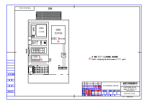
CH14 连接器1. 简介在计算机科学中,连接器(Connector)是指用于连接电子元器件或设备之间的接口。
连接器通常是由金属或塑料制成,具有规范的物理尺寸和布局,以便于正确连接设备。
本文将介绍常见的连接器类型、其工作原理和使用场景。
2. USB 连接器USB(Universal Serial Bus)是一种常见的连接器类型,用于在计算机和外部设备之间传输数据和供电。
USB连接器通常具有Type-A、Type-B、Micro USB和USB-C等不同类型,每种类型适用于特定的设备和用途。
2.1 Type-AType-A连接器是最常见的USB连接器,大多用于连接计算机主机与外部设备,如打印机、键盘、鼠标等。
Type-A连接器具有矩形形状,一端带有四个导线和两个接地片。
2.2 Type-BType-B连接器通常用于连接外部设备,如打印机、扫描仪等,与Type-A连接器相互配合实现数据传输。
Type-B连接器具有正方形形状,一端带有四个导线和两个接地片。
2.3 Micro USBMicro USB连接器是一种小型的USB连接器,常用于移动设备,如手机、平板电脑等。
Micro USB连接器相对于Type-A和Type-B连接器更小巧,具有易于插拔和高耐用性的优点。
2.4 USB-CUSB-C连接器是一种新型的USB连接器,具有倒插特性和全向性插拔,使连接更加方便和灵活。
USB-C连接器支持高速数据传输和快速充电,因此被广泛应用于手机、笔记本电脑、显示器等设备。
3. Ethernet 连接器Ethernet连接器用于连接计算机网络设备,实现数据传输和通信。
最常见的Ethernet连接器类型是RJ-45连接器,具有八个插孔和金属夹片,用于连接网络适配器、交换机、路由器等设备。
3.1 RJ-45RJ-45连接器由金属或塑料制成,通常用于以太网(Ethernet)连接。
RJ-45连接器具有八个插孔,其中四个用于数据传输,另外四个用于电源供应和信号屏蔽。
AIG-500系列進階IIoT閘道器,配備Intel Atom®四核心1.91GHz處理器、1個VGA連接埠、ThingsPro Edge軟體、-40至70°C工作溫度特色與優點•ThingsPro Edge軟體簡化資料採集和裝置管理•ThingsPro Edge和Azure IoT Edge的無縫整合可實現簡單、可靠且安全的雲端連線•支援使用ThingsPro Proxy工具程式輕鬆部署裝置•提供強大的OTA功能,防止軟體升級過程中出現系統故障•配備安全啟動以防惡意軟體注入攻擊認證簡介AIG-500系列進階IIoT閘道器專為工業物聯網應用而設計,特別適用於嚴苛操作環境中的分散式和無人站點。
ThingsPro Edge和Azure IoT Edge軟體已預先載入並與AIG-500系列無縫整合,使用Azure雲端解決方案實現簡單、可靠、安全的感測器到雲端連線,用於資料採集和裝置管理。
使用ThingsPro Proxy工具程式,裝置部署過程比以往更容易。
由於強大的OTA功能,完全不需要擔心軟體升級過程中的系統故障。
啟用安全啟動功能後,您可以啟用AIG-500系列的啟動程序,以防惡意軟體注入攻擊。
外觀規格ComputerCPU Intel Atom®Processor E3845(2M Cache,1.91GHz)Graphics Controller Intel®HD GraphicsDRAM4GB DDR3LStorage Pre-installed32GB CFast GB eMMCPre-installed OS Linux Debian9,Kernel4.9Computer InterfaceTPM TPM v2.0Ethernet Ports Auto-sensing10/100/1000Mbps ports(RJ45connector)x4Serial Ports RS-232/422/485ports x4,software selectable(DB9male)Digital Input DIs x4Digital Output DOs x4USB2.0USB2.0hosts x2,type-A connectorsWi-Fi Antenna Connector AIG-501-T-AZU-LX:RP-SMA x2Cellular Antenna Connector AIG-501-T-US-AZU-LX:SMA x2AIG-501-T-EU-AZU-LX:SMA x2AIG-501-T-AP-AZU-LX:SMA x2GPS Antenna Connector AIG-501-T-US-AZU-LX:SMA x1,AIG-501-T-AP-AZU-LX:SMA x1,AIG-501-T-EU-AZU-LX:SMA x1Number of SIMs1Expansion Slots AIG-501-T-AZU-LX:mPCIe slot x1SIM Format MiniVideo Output VGA x1,15-pin D-sub connector(female)Ethernet InterfaceMagnetic Isolation Protection 1.5kV(built-in)Serial InterfaceConnector DB9maleBaudrate300bps to921.6kbpsData Bits5,6,7,8Flow Control ADDC®(automatic data direction control)for RS-485,RTS/CTS,XON/XOFFParity None,Even,Odd,Space,MarkStop Bits1,1.5,2Isolation N/ASerial SignalsRS-232TxD,RxD,RTS,CTS,DTR,DSR,DCD,GNDRS-422Tx+,Tx-,Rx+,Rx-,GNDRS-485-2w Data+,Data-,GNDRS-485-4w Tx+,Tx-,Rx+,Rx-,GNDDigital InputsConnector Spring-type Euroblock terminalSensor Type Dry contactDry Contact Off:openOn:short to GNDIsolation NoneDigital OutputsConnector Spring-type Euroblock terminalCurrent Rating10mA(max.)total for all channelsI/O Type SinkIsolation NoneCellular InterfaceCellular Standards LTE CAT-4Band Options(US)LTE Band2(1900MHz)/LTE Band4(1700MHz)/LTE Band5(850MHz)/LTE Band12(700MHz)/LTE Band13(700MHz)/LTE Band14(700MHz)/LTE Band66(1700MHz)/LTE Band71(600MHz)UMTS/HSPA Band2(1900MHz)/Band4(1700MHz)/Band5(850MHz)Carrier Approval:Verizon,AT&TBand Options(EU)LTE Band1(2100MHz)/LTE Band3(1800MHz)/LTE Band7(2600MHz)/LTE Band8(900MHz)/LTE Band20(800MHz)/LTE Band28A(700MHz)UMTS/HSPA Band1(2100MHz)/Band3(1900MHz)/Band8(900MHz)Band Option(APAC)LTE Band1(2100MHz)/LTE Band3(1800MHz)/LTE Band5(850MHz)/LTE Band8(900MHz)/LTE Band9(MHz)/LTE Band18(850MHz)/LTE Band19(850MHz)/LTEBand28(700MHz)UMTS/HSPA Band1(2100MHz)/Band5(850MHz)/Band6(800MHz)/Band8(900MHz)/Band19(800MHz)GPS InterfaceReceiver Types GPS/GLONASS/BeiDou/Galileo/QZSSAccuracy0.8mAcquisition-147dBmSensitivity Cold starts:-145dBmTracking:-160dBmLED IndicatorsSystem Power x1Storage x1LAN2per port(10/100/1000Mbps)Serial2per port(Tx,Rx)ThingsPro SoftwareThingsPro Proxy Utility YesAzure IoT Edge Preintegrated YesThingsPro Edge Preloaded YesPower ParametersInput Voltage12to36VDCPower Connector Screw-fastened Euroblock terminalPower Consumption30W(max.)Input Current 2.5A@12VDCReliabilityAutomatic Reboot Trigger External WDT(watchdog timer)Physical CharacteristicsHousing MetalInstallation DIN-rail mounting(with optional kit),Wall mounting(with optional kit)IP Rating IP20Dimensions132x122x87mm(5.2x4.81x3.43in)Weight1,340g(2.95lb)Environmental LimitsAmbient Relative Humidity5to95%(non-condensing)Operating Temperature-40to70°C(-40to158°F)Storage Temperature(package included)-40to75°C(-40to167°F)Shock IEC60068-2-27Vibration IEC60068-2-64Standards and CertificationsSafety EN62368-1,UL60950-1EMC EN55032/35,EN61000-6-2/-6-4EMI CISPR32,FCC Part15B Class AEMS IEC61000-4-2ESD:Contact:4kV;Air:8kVIEC61000-4-3RS:80MHz to1GHz:10V/mIEC61000-4-4EFT:Power:2kV;Signal:1kVIEC61000-4-5Surge:Power:1kV;Signal:1kVIEC61000-4-6CS:10VIEC61000-4-8PFMFRED EN300328EN301893EN301489-1/17/19/52EN301511EN301908-1EN303413EN62311Green Product RoHS,CRoHS,WEEEHazardous Locations Class I Division2,ATEXMTBFTime441,032hrs(AIG-501-T-US-AZU-LX,AIG-501-T-EU-AZU-LX,AIG-501-T-AP-AZU-LX)453,637hrs(AIG-501-T-AZU-LX)Standards Telcordia(Bellcore)Standard TR/SRWarrantyWarranty Period3yearsDetails See /tw/warrantyPackage ContentsDevice1x AIG-500Series computerDocumentation1x quick installation guide1x warranty cardInstallation Kit1x power jack尺寸訂購資訊Model Name CPU RAM Storage TPM mPCIe SlotOperating TemperatureAIG-501-T-AZU-LX 1.91GHz4GB32GB Built-in Reserved for Wi-Fimodule-40to70°CAIG-501-T-US-AZU-LX 1.91GHz4GB32GB Built-in US region LTEmodulepreinstalled-40to70°CAIG-501-T-EU-AZU-LX 1.91GHz4GB32GB Built-in Europe region LTEmodulepreinstalled-40to70°CAIG-501-T-AP-AZU-LX 1.91GHz4GB32GB Built-in APAC region LTEmodulepreinstalled-40to70°C配件(選購)Power WiringCBL-PJTB-10Non-locking barrel plug to bare-wire cableMini DB9F-to-TB DB9female to terminal block connectorWi-Fi Wireless ModulesUC-8200-WLAN22-AC Wireless package for UC-8200V2.0or later with Wi-Fi module,2screws,2spacers,1heat sink,1pad AntennasANT-LTEUS-ASM-01GSM/GPRS/EDGE/UMTS/HSPA/LTE,1dBi,omnidirectional rubber-duck antennaANT-LTE-ASM-04BK704to960/1710to2620MHz,LTE omnidirectional stick antenna,4.5dBiANT-LTE-OSM-03-3m BK700-2700MHz,multiband antenna,specifically designed for2G,3G,and4G applications,3m cable ANT-LTE-ASM-05BK704-960/1710-2620MHz,LTE stick antenna,5dBiANT-LTE-OSM-06-3m BK MIMO Multiband antenna with screw-fastened mounting option for700-2700/2400-2500/5150-5850MHzfrequenciesANT-WDB-ARM-02022dBi at2.4GHz or2dBi at5GHz,RP-SMA(male),dual-band,omnidirectional antennaANT-GPS-OSM-03-3m BK3dBi at1575.42MHz,SMA(male),omnidirectional magnetic-base passive GPS antenna,3m cableANT-GPS-OSM-05-3M26dBi at1575.42MHz,SMA(male),omnidirectional active GPS antenna,3m cableDIN-Rail Mounting KitsMC-1100DIN-Rail Kit DIN-rail mounting kit,4screwsWall-Mounting KitsUC-8200Wall-mounting Kit Wall-mounting kit for UC-8200with4M3screws©Moxa Inc.版權所有.2022年1月24日更新。
WA-144-E 4/1/2004 APPLICATION: Tractors: Super 55, Super 66 Oliver; 550 Oliver Thru # 72831;QTY ITEM # DESCRIPTION LETTERED ITEMSINCLUDED IN KIT1 994184 In-Frame Kit, STD 3.500" Bore I1 994129 In-Frame Kit, 3.625" Overbore I1 995184 Out-of-Frame Kit, STD 3.500" Bore O 1 995129 Out-of-Frame Kit, 3.625" Overbore O4 191197 Sleeve & Piston Assembly, STD 3.500" Bore O I 4 191195 Sleeve & Piston Assembly, STD 3.625" Bore O I 4 191179 Piston Assembly, 3.625" Overbore 4 191181 Cylinder Liner, 3.625" Overbore (Includes O-Rings)4 191138 Cylinder Liner O-Ring Package 1 191182 Block Repair Sleeve, Lower Liner Pilot Bore 4 191187 Piston Ring Set, STD 3.500" Bore (3-1/8 1-3/16) 4 191177 Piston Ring Set, STD 3.500" Bore (3-1/8 1-1/4)4 191189 Piston Ring Set, 3.5625" Overbore (3-3/32 1-1/4)4 191191 Piston Ring Set, 3.5625" Overbore (3-1/8 1-1/4)4 191196 Piston Ring Set, STD 3.625" Bore (3-3/32 1-3/16)1 191198 Piston Ring Set, STD 3.625" Bore (3-3/32 1-1/4)1 191199 Piston Ring Set, 3.750" Overbore (3-3/32 1-1/4)4 191174 Piston Ring Set, 3.750" Overbore (3-1/8 1-3/16)1 191211 Piston Ring Set, 3.750" Overbore (3-1/8 1-1/4)4 291163 STD Rod Bearing O O I I 4 291164 .002 Rod Bearing 4 291165 .003 Rod Bearing4 291166 .010 Rod Bearing 4 291167 .020 Rod Bearing 4 291168 .030 Rod Bearing 4 291169 .040 Rod Bearing1 291185 STD Main Bearing Set O O I I1 291186 010 Main Bearing Set 1 291187 020 Main Bearing Set1 291188 030 Main Bearing Set1 391238 In-Frame Gasket Set I I1 391228 Head Gasket6 391217 Manifold Gasket 1 391226 Valve Cover Gasket, Cast Cover (Rubber) 1 391227 Valve Cover Gasket, Pressed Steel Cover (Cork)1 391239 Full Gasket Set w/Seals O O1 391159 Timing Cover Gasket1 391237 Rear Seal Housing Gasket1 391225 Pan Gasket1 391142 Front Crank Seal (Face Type) 1 391184 Front Pulley Felt Seal1 391147 Rear Crank Seal (Face Type)1 391148 Rear Lip Seal Conversion Kit(Hsg, Seal, Gkt, Bolts, Dowels)4 291147 Pin Bushing (1 Piece Bushing Upgrade) 1 291148 Cam Bearing8 791129 Rod Bolt8 791131 Rod NutWA-144-E 4/1/2004 APPLICATION: Tractors: Super 55, Super 66 Oliver; 550 Oliver Thru # 72831;QTY ITEM # DESCRIPTION LETTERED ITEMSINCLUDED IN KIT1 999518 Cam Kit C 1 999144 Valve Train Kit V1 591152 Camshaft (3/16" Key) C 1 591124 Cam Key (3/16 X 1) 1 591126 Cam Thrust Spring 1 591127 Cam Thrust Button8 591123 Tappet C4 4 491191 491192 Exhaust Valve, Gasoline (1.250" Hd Dia) Intake Valve (1.400" Hd Dia) V V4 491188 Exhaust Valve Guide V 4 491164 Intake Valve Guide V4 491147 Exhaust Valve Spring (Use Only w/Rotator) V 4 491172 Intake Valve Spring V 4 491148 Exhaust Valve Rotator V 16 491149 Valve Keeper, Late (2 Lands) V 8 491158 Valve Spring Cup (Needed When Replacing Flanged Guides)4 491153 LH Rocker Arm4 491154 RH Rocker Arm1 491217 Rocker Arm Shaft8 491169 Rocker Arm Adjusting Screw2 491139 Rocker Arm Shaft Spring1 591136 Cam Timing Gear (3/16" Key) 1 591128 Crank Timing Gear8 591137 Push Rod, Super 55 Thru ESN 968269 (11.047" OAL)8 591137 Push Rod, Super 66 Thru ESN 957400 (11.047" OAL)8 591143 Push Rod, Super 55 After ESN 968269; 550 (10.891" OAL) 8 591143 Push Rod, Super 66 After ESN 957400 (10.891" OAL)1 691136 Oil Pump Assembly 1 691137 Oil Pump Screen 1 691129 Oil Pump Kit (2-Blades 1-Spring 1-Shaft 1-Gear 1-Hdw Pkg) 1 691131 Oil Pump Repair Kit (2-Blades 1-Spring)1 691132 Oil Pump Drive Gear1 691135 Oil Relief Valve Spring (1 9/16" Long)1 791132 Plug, Block/Cam (2" Flat Brass)1 791124 Plug, Oil Galley (21/32" Cup)5 791133 Plug, Cylinder Head (1" Flat Brass)1 291159 Governor Bushing, 1 1/8" OD (Front of Block)1 291161 Governor Bushing, 1 3/8" OD (Front of Block)1 291162 Governor Thrust Washer1 891151 New Water Pump (Cast# 190060, 190160, 190360)1 891155 New Water Pump (Cast# 180060, 180160)1 891148 Thermostat1 891142 Coolant Heater。
P/N: 1802051140010 *1802051140010*MGate 5114Quick Installation GuideEdition 1.0, November 2018Technical Support Contact Information/supportMoxa Americas:Toll-free: 1-888-669-2872 Tel: 1-714-528-6777 Fax: 1-714-528-6778 Moxa China (Shanghai office): Toll-free: 800-820-5036 Tel: +86-21-5258-9955 Fax: +86-21-5258-5505 Moxa Europe:Tel: +49-89-3 70 03 99-0 Fax: +49-89-3 70 03 99-99 Moxa Asia-Pacific:Tel: +886-2-8919-1230 Fax: +886-2-8919-1231 Moxa India:Tel: +91-80-4172-9088 Fax: +91-80-4132-10452018 Moxa Inc. All rights reserved.OverviewThe MGate 5114 is an industrial Ethernet gateway for ModbusRTU/ASCII/TCP and IEC 60870-5-101/104 network communications. Package ChecklistBefore installing the MGate 5114, verify that the package contains the following items:• 1 MGate 5114 gateway• 1 serial cable: DBL-RJ45F9-150•Quick installation guide (printed)•Warranty cardPlease notify your sales representative if any of the above items is missing or damaged.Optional Accessories (can be purchased separately)•CBL-F9M9-150: DB9-female-to-DB9-male serial cable, 150 cm •CBL-F9M9-20: DB9-female-to-DB9-male serial cable, 20 cm •CBL-RJ45F9-150: RJ45-to-DB9-female serial cable, 150 cm •CBL-RJ45SF9-150: RJ45-to-DB9-female serial shielded cable, 150 cm•Mini DB9F-to-TB DB9: Female-to-terminal-block connector •DK-25-01: 1 DIN-rail kit with 2 screws•WK-36-02: Wall-mounting kit, 2 plates with 6 screws•CBL-PJTB-10: Non-locking barrel plug to bare-wire cable Hardware IntroductionLED IndicatorsAgent Mode:LED Color DescriptionReady Off Power is off or a fault condition existsGreen Steady: Power is on, and the MGate isfunctioning normallyRed Steady: Power is on, and the MGate is bootingupBlinking slowly: Indicates an IP conflict, or theDHCP or BOOTP server is not respondingproperlyFlashing quickly: the microSD card failedMB* Off No serial communication with Modbus device Green Normal Modbus serial communication inprogressRed An error in serial communication occurredWhen the MGate 5114 acts as a ModbusRTU/ASCII master:1.The slave device returned an error(exception)2.Received a framing error (parity error,checksum error)3.Timeout (the master sends but noresponse)When the MGate 5114 acts as a ModbusRTU/ASCII slave:1.Received an invalid function codeThe master accessed an invalid registeraddress or coil address2.Received a framing error (parity error,checksum error)101* Off No serial communication with the IEC 60870-5-101 deviceGreen Normal IEC 60870-5-101 serial communicationin progressRed An error in serial communication occurredWhen the MGate 5114 acts as an IEC 60870-5-101 master:1.Received a slave exception (format error,checksum error, invalid data, slaveresponds are not supported)2.Timeout (the master sends but noresponse)When the MGate 5114 acts as an IEC 60870-5-101 slave:Received a master exception (format error,checksum error, invalid data)*Only indicates serial communication status; for IEC 60870-5-104 or Modbus TCP status, please refer to the LED indicator on the Ethernet port.DimensionsUnit: mm (inch)Reset ButtonRestore the MGate to factory default settings by using a pointed object (such as a straightened paper clip) to hold the reset button down until the Ready LED stops blinking (approximately five seconds).Pull-high, Pull-low, and Terminator for RS-485Beneath the MGate 5114’s top cover, you will find DIP switches to adjust each serial port’s pull-high resistor, pull-low resistor, and terminator.SW 1 2 3 Pull-high resistor Pull-low resistor Terminator ON1 kΩ 1 k Ω 120 Ω OFF 150 k Ω*150 k Ω*–**DefaultHardware Installation Procedure1. Connect the power adapter. Connect the 12-48 VDC power line orDIN-rail power supply to the MGate 5114’s terminal block.2. Use a serial cable to connect the MGate to the Modbus RTU/ASCIIor IEC 60870-5-101 device.3. Use an Ethernet cable to connect the MGate to the Modbus TCP orIEC 60870-5-104 device.4. The MGate 5114 is designed to be attached to a DIN rail ormounted on a wall. For DIN-rail mounting, push down the spring and properly attach it to the DIN rail until it “snaps” into place. For wall mounting, install the wall-mount kit (optional) first and then screw the device onto the wall.The following figure illustrates the two mounting options:Software Installation InformationYou can download the User's Manual and Device Search Utility (DSU) from Moxa's website: . Please refer to the User’s Manual for additional details on using the DSU.The MGate 5114 also supports login via a web browser. Default IP address: 192.168.127.254 Default account: admin Default password: moxaPin AssignmentsSerial Port (Male DB9) PinRS-232RS-422/ RS-485 (4W)RS-485 (2W) 1 DCD TxD-(A) – 2 RXD TxD+(B) –3 TXD RxD+(B)Data+(B) 4 DTR RxD-(A) Data-(A) 5* GND GND GND 6 DSR – – 7 RTS – – 8 CTS – – 9 – ––*Signal groundEthernet Port (RJ45) Pin Signal 1 Tx+ 2 Tx- 3 Rx+ 6Rx-Power Input and Relay Output PinoutsV2+V2-V1+V1-ShieldedGroundDC Power Input 2 DCPowerInput 2 N.O.CommonN.C.DC Power Input 1 DC Power Input 1SpecificationsPower Requirements Power Input 12 to 48 VDC Input Current455 mA max.Operating TemperatureStandard models:0 to 60°C (32 to 140°F) Wide temp. models:-40 to 75°C (-40 to 167°F)Ambient Relative Humidity 5 to 95% (non-condensing) Dimensions 36 x 105 x 140 mm (1.42 x 4.14 x 5.51 in) Reliability Alert Tools Built-in buzzer and RTC MTBF 1,140,815 hrs.。
V1.1Quick Start Guideクイックスタートガイド퀵�스타트�가이드Kurzanleitung Guida rapida Guide de démarrage rapide Guía de inicio rápido Краткое руководство01-12 13-25 26-38 39-51 52-64 65-77 78-90 91-103Disclaimer and WarningThank you for purchasing the Hohemproduct.By using this product, you hereby signify that you have read this disclaimer and warning carefully and that you understand and agree to abide by the terms andconditions herein. You agree that you aresolely responsible for your own conduct while using this product, and for any consequences thereof. You agree to use this product only for purposes that are proper and in accordance with all applicable laws, rules, andregulations, and all terms, precautions,practices, policies and guidelines Hohem has made and may make available. Hohemaccepts no liability for damage, injury or any legal responsibility incurred directly or indirectly from the use of this product. The user shall observe safe and lawful practices including,but not limited to, those set forth in this document.ContentsDownload the Hohem Pro App iSteady V2 Overview Mounting and BalancingActivation & Bluetooth Connection AI Visual Tracking & LED Video Light Button FunctionWorking Mode & Follow Speed How to fold the gimbal?Use as emergency power bank How to do if the gimbal is not level after powering on?Power indicator and Bluetoothindicator function Specifications Warranty Card01020304050607090909101111Scan the QR code to enter the download page Search " Hohem Pro " in the App Store or Google Play*Hohem Pro app requires iOS 10.0 or above, Android 6.0 or above *More product tutorials can be found on the app homepageDownload the Hohem Pro App, Register and LoginWhen powering on iSteady V2 at first use, activation is required throughHohem Pro app. iSteady V2 works after the activation.Mount your mobile phone before powering on iSteady V2.If no mobile phone is detected or the motor is overloaded due to phoneis not level, the gimbal will shut down after a warning beeping.Important Notes:○○○○iSteady V2 OverviewAI Vision Sensor & LED Video Light Power ButtonAI Vision Indicator AI Vision Sensor LED Video Light Phone Clamp Folding Lock A Folding Lock BBattery Indicator Zoom SliderShutter Button Tilt Motor Knob Pan Motor Bluetooth Light JoystickPower (ON/OFF) /Function Button01.02.03.04.05.06.07.08.09.10.11.12.13.14.15.16.Roll Motor Bidirectional chargingport (Type C)ResetHandle(Battery built-in)Lanyard Hole1/4 inch Screw Port17.18.19.20.21.22.01020*******06070809101314151617201918222104①Unfold the gimbal②Screw up theknob③Turn the “hohem”logoupward④Put your phone stuck in the bottom of phone clamp and pull the head of phone clamp to mount your phone.⑤Slide the phone and make sure it is clamped in the middle, power on the gimbal after balancing thephone clamp.The gimbal would work improperly if not screw the knob up.Clench the phone clamp, ensuring that your phone is cling to the rubber mat, otherwise the gimbal would vibrate or turn off automatically.How to mount and balance mobile phone on the gimbal?For the first time, please turn on the gimbal. Log into the Hohem Pro app to activate the gimbal. Gimbal will work improperly if not been activated.① StartupLong press the function button. At the first start, it will enter a to-be-activated state and the Bluetooth indicator will flash alternately in red and green.② Bluetooth connection through the APPTurn on the bluetooth of phone. Log into the app Hohem Pro.Following the notice at the top for connection.③ Activate iSteady V2After the Bluetooth is connected, an activation prompt box will pop up. Click "Confirm" to complete the activation. Three beeps for noticing you the activation has done, and you can use the gimbal now.Booting up iSteady V2 at first useActivation & Bluetooth ConnectionLED Video LightSingle press the power button to start, the indicator light shows red, and the LED video light double flashes to indicate that the AI visual tracking has been activated (long press the power button to turn off)Please note: The best distance of gesture control is between 0.5 and 1.5 meters (1.6-5 ft) , and make sure that bothgesture and face are shown in front of AI senser within this range.AI Visual TrackingAI Visual Tracking & LED Video LightPortrait mode: Thumbs-rightSwitch between landscape and portrait mode: Two hands facing towards the AI vision sensorLandscape mode: Thumbs-up Press AI vision sensor & LED video light power button to adjust the light intensity, LED turns according to low-medium-high-close modes.Start smart tracking: take a OK gesture towards the AI vision sensor, AI vision indicator will turn greenTurn off smart tracking: show a palm gesture towards the AI vision sensor and AI vision indicator will turn redButton Function③ Zoom Slider (Only available in the app) Push Up: Zoom in Push Down: Zoom out ④ Shutter Button (Ensure the Bluetooth is connected) Single Press: Take photo, Start/End video Double Press: Switch photo/video modes Triple Press: Switch front/rear cameras (Only available in the app)② JoystickUp/Down:Tilt ControlLeft/Right:Pan Control(It is able to control the roll motorthrough Left/Right Joystick Settingsin Hohem Pro app)① Power (ON/OFF) / Function ButtonLong Press:Power On/OffSingle Press:Switch the landscape and portrait modes Double Press: Recenter the gimbalTriple Press: Inception (Auto rotation)Press Five Times: Auto calibrationPress Seven Times: Remote control pairingThe bluetooth light will flash alternately in yellow and green. (The remote control is an optional accessory)a. If the remote control is not paired within 30 seconds, the pairing will be cancelled;b. Click the function button to cancel pairing;c. Double-click the function button to clear the paired remote control and cancel pairing;(And the paired remote control will be unavailable and need to be re-paired)Working ModePan&Tilt FollowThis is the default working mode. When you rotate the handle left/right/tilt up/tilt down, the camera will follow the handle movements, and the roll motor is locked without following the movement.*For changing working mode or follow speed, please open Hohem Pro app - Start Recording - Gimbal Parameter Settings*Ensure the Bluetooth is connected and change the settingsWorking Mode & Follow SpeedHow to switch working modes by button?Combination operation: Press and hold shutter button and tap power button Single Tap: Pan&Tilt Follow (Default) Double Tap: Pan FollowTriple Tap: All Lock Quartic Tap: POV (All Follow)*Tips: To ensure proper operation, please release the shutter button after the power button.Pan FollowWhen you rotate the handle left/right, the camera will follow the handle movements. The tilt motor does not follow within the angle range of -30°~+30 movement, if exceed this range, the gimbal will follow the tilt movement, and the roll motor is locked without following the movement.All LockThe roll and pan motors are locked without following the movement. The tilt motor does not follow within the angle range of -30°~+30 movement, if exceed this range, the gimbal will follow the tilt movement.POV (All Follow)First person point of viewGives you 360° complete movement, you can pan, tilt and roll with it.Follow SpeedGeneral Shooting with general follow speedSlow Shooting with slow follow speedMedium Shooting to follow the fast movementFast Fast follow speed for video transitionIf the gimbal is not level after turned on, or pan axis is slight drift when the gimbal is still, please calibrate the gimbal on a stationary and horizontal surface.How to fold Gimbal?How to do if the gimbal is not level after powering on?① Turn on the gimbal, press function button 5 times ② Start calibration after a beep sound ③ The battery indicator light keep flashing④ The calibration is done after two beeps sound (the calibration takes about 40 seconds)The gimbal can be used as emergency charging for your mobile phone and other electronic devices.Use as emergency power bankPower Indicator LightsStay on: Fully charged or charging complete Single flashing:Charging Continous Flashing:Calibrating Power indicator and Bluetooth indicator functionBluetooth Indicator Light1. A.Blinks red and green alternatively:To be activated (at first use)B.Blinks yellow and green alternatively:The remote control is pairing (The remote control is an optional accessory)3. Blinking indicators of working modes Solid Light:Pan& Tilt Follow Flash twice:Pan Follow Flash triple:All Lock Flash four times:POV (All Follow)Pulse:Standby mode2. Color indicates the status of gimbal Green :Bluetooth is connected Yellow :Bluetooth is not connected Red :Warning of abnormal loads on the stabilizer or failed firmware upgradeWarranty CardUser Name:Contact No.:Address:Purchase Date:Prod. Serial No.:Failure Issue:Service Record:SpecificationsThe motor would be shown in the screen due to some of mobile cameras aredesigned at the middle of phone, such as Xiaomi10, Xiaomi10 Pro, Xiaomi CC9 PRO.iSteady V2263g179 X 79 X 39 mm 18650li-ion 2800mAh9 hours4 hours (with AI vision sensor)2 hours (with AI vision sensor & LED video light)* Pan: 320°* Roll: 320°* Tilt: 320°* Pan: 320° * Tilt: -30°~+30°Weight :≤280gThickness:≤11 mm Width:55mm~90mmModel WeightFolded Dimensions BatteryOperating TimeMechanical RangeControllable RangeCompatible Phones Bidirectional charging port (Type C) supports gimbal works while charging.Email:*****************Website: Manufacturer: Hohem Technology Co., Ltd.Contact us at Facebook -@HohemTechOfficial-Contact usWithin 15 days upon the purchase date. Any functional disorder or quality problem enjoys free replacement service. But ensure the commodity and package with no damage, and we will offer a brand new replacement after confirming the product problem.Warranty valid only under normal use.Used in the normal circumstances, 1 year warranty, maintenance of life (not include the All accidents or artificial damage, improper disassembly or misuse damage is NOT covered by the warranty.)Please keep and offer the warranty card for claiming the warranty service.1.2.4.3.CALL CENTER -Toll FreeUNITED STATES:+1(888)9658512Mon-Fri: 9:00AM-5:00PM(EST)UNITED KINGDOM:+44(0)808 2737578Mon-Fri: 2:00PM-10:00PM(GMT +0)CANADA:+1(855)758-8939Mon-Fri: 9:00AM-5:00PM(EST)BRAZIL:+55 (0)800 5911897Mon-Fri: 10:00AM-6:00PM(GMT -3)。
Chapter 14桟onstruct, Deliver, and Maintain Systems ProjectsTRUE/FALSE1. The detailed design phase of the Systems Development Life Cycle is a linear process with each of fivesteps occurring once and in its proper sequence.ANS: F2. In a Computer Aided Software Engineering (CASE) environment, the most important use of a dataflow diagram is to present a graphic display of the system.ANS: F3. During maintenance of a system developed using Computer Aided Software Engineering (CASE)tools, changes to the system are made directly through the data flow diagram.ANS: T4. The Computer Aided Software Engineering (CASE) coding model transforms the structure diagraminto computer code.ANS: T5. If system development is conducted properly, most system maintenance costs can be eliminated.ANS: F6. The context level data flow diagram is a physical input to the lower CASE models that automaticallyproduce program code.ANS: F7. The design and programming of modern systems follows one of two basic approaches: the structuredapproach and the object-oriented approach.ANS: T8. The concept of reusability is central to the structured approach to systems design.ANS: F9. In the object-oriented approach to systems design, a vendor is an example of an attribute.ANS: F10. In the object-oriented approach to systems design, an instance is a logical grouping of individualobjects which share the same attributes and operations.ANS: F11. In the object-oriented approach to systems design, when an operation is performed on an object, anattribute will always be changed.ANS: F12. In the object-oriented approach to systems design, inheritance means that each object instance inheritsthe attributes and operations of the class to which it belongs.ANS: T13. In the object-oriented approach to systems design, it is possible for an object class to inherit attributesand operations of another object class.ANS: T14. The entity relationship diagram is used to represent object-oriented designs.ANS: T15. Office automation is more complex than accounting packages.ANS: F16. In-house developed systems are less reliable than commercial software.ANS: T17. Output of the Management Reporting System may vary considerably among companies.ANS: T18. Output reporting includes both paper and electronic reports.ANS: T19. Information as to which databases are required for a new system can be obtained from the entityrelationship diagram.ANS: T20. A point-of-sale terminal is an example of electronic data input from source documents.ANS: F21. Correctly designed, processing modules are tightly coupled and have strong cohesion.ANS: F22. A system walkthrough occurs after the system is implemented.ANS: F23. The detailed design report is the 揵lueprint which guides programmers and database administratorsin constructing the physical system.ANS: T24. When a program module is tested, both good and bad data are included with the test transactions.ANS: T25. Instruction for the filling out of paper input forms should always be printed on a separate instructionsheet.ANS: F26. Program modules with weak cohesion are more complex and difficult to maintain.ANS: T27. If individual modules are thoroughly tested, it is not necessary to test the whole system.ANS: FMULTIPLE CHOICE1. Which statement is not true?a. prototypes do not include internal control featuresb. a prototype is an inexpensive, simplified model of a systemc. a throwaway prototype is discarded after the requirements are establishedd. systems designers always discard prototypes and do not develop them into finishedsystemsANS: D2. Which statement is not true? Computer Aided Software Engineering (CASE) technologya. is commercially available softwareb. reduces the productivity but increases the quality of the work of systems professionalsc. expedites the System Development Life Cycled. consists of upper and lower toolsANS: B3. The central repository of the Computer Aided Software Engineering (CASE) system containsa. the program codeb. user prototype screensc. data flow diagramsd. all of the aboveANS: D4. Which is not a level of a data flow diagram?a. conceptual levelb. context levelc. intermediate leveld. elementary levelANS: A5. Which level of a data flow diagram is used to produce program code and database tables?a. context levelb. elementary levelc. intermediate leveld. prototype levelANS: B6. In a Computer Aided Software Engineering (CASE) environment, a structure diagrama. presents an overview model of the primary transactions processedb. graphically depicts the iceberg effectc. presents a model of the program code that constitutes the physical systemd. is prepared by the systems analystANS: C7. An advantage of the Computer Aided Software Engineering (CASE) model tool, which transforms thestructure diagram into machine language, isa. it facilitates the auditors review of the systemb. it ensures that firm will use a specific CASE tool and vendorc. it forces all system changes to be made through the data flow diagramsd. it reduces the analysis required in designing the systemANS: C8. When maintaining a system that was developed using Computer Aided Software Engineering (CASE)tools,a. the programmer must thoroughly review the program codeb. changes should be made directly to the structure diagramc. significantly less time is required compared to maintenance activities for a systemdeveloped without using Computer Aided Software Engineering (CASE) toolsd. the need for testing the modified application is eliminatedANS: C9. Which of the following is an advantage of the Computer Aided Software Engineering (CASE)approach?a. the ability to easily revise the model during the development stageb. the requirement that all program code and documentation be regenerated for each modulec. the cost of software engineering programsd. user involvement is restricted to final stages of developmentANS: A10. Which of the following is a disadvantage of the Computer Aided Software Engineering (CASE)approach?a. source code produced by CASE tools is less efficient than code written by a skilledprogrammerb. alternative designs cannot be reviewed prior to implementationc. system users are reluctant to become involved with the CASE approachd. maintenance costs are increasedANS: A11. Which statement is not correct? The structured design approacha. is a top-down approachb. is documented by data flow diagrams and structure diagramsc. assembles reusable modules rather than creating systems from scratchd. starts with an abstract description of the system and redefines it to produce a more detaileddescription of the systemANS: C12. The benefits of the object-oriented approach to systems design include all of the following excepta. this approach does not require input from accountants and auditorsb. development time is reducedc. a standard module once tested does not have to be retested until changes are maded. system maintenance activities are simplifiedANS: A13. In the object-oriented systems design approach, the employee pay rate is an example ofa. an objectb. an attributec. an operationd. a classANS: B14. Ms. Andrews is a customer of the Edsell Company. In the object-oriented design approacha. Ms. Andrews is an instance in the object class accounts receivableb. the amount Ms. Andrews owes the Edsell Company is an operationc. determining the amount past due is an attributed. the object class accounts receivable inherits all the attributes of Ms. AndrewsANS: A15. In the object-oriented systems design approach,a. objects possess two characteristics朼ttributes and instancesb. an instance is a logical grouping of individual objectsc. inheritance means that each object instance inherits the attributes and operations of theclass to which it belongsd. operations performed on objects always change attributesANS: C16. Which statement is not correct? In the object-oriented design approacha. a single change to an attribute or operation in one object class is automatically changed forall the object instances and subclasses that inherit the attributeb. each module can inherit from other modules the attributes and operations it requiresc. the entity relationship diagram is used to create a program which can be used in othersystemsd. the control module must be recreated for each programANS: D17. Evaluators of the detailed feasibility study should not includea. the internal auditorb. the project managerc. a user representatived. the system designerANS: D18. A commercial software system that is completely finished, tested, and ready for implementation iscalled燼a. backbone systemb. vendor-supported systemc. benchmark systemd. turnkey systemANS: D19. Which of the following is not an advantage of commercial software? Commercial softwarea. can be installed faster than a custom systemb. can be easily modified to the user抯exact specificationsc. is significantly less expensive than a system developed in-housed. is less likely to have errors than an equivalent system developed in-houseANS: B20. Which step is least likely to occur when choosing a commercial software package?a. a detailed review of the source codeb. contact with user groupsc. preparation of a request for proposald. comparison of the results of a benchmark problemANS: A21. The output of the detailed design phase of the Systems Development Life Cycle (SDLC) is aa. fully documented system reportb. systems selection reportc. detailed system design reportd. systems analysis reportANS: C22. The detailed design report contains all of the following excepta. input screen formatsb. alternative conceptual designsc. report layoutsd. process logicANS: B23. When each element of information supports the user抯decision or task, the output is said to possessa. completenessb. summarizationc. concisenessd. relevanceANS: D24. There is often a conflict between the attributes ofa. timeliness and concisenessb. accuracy and timelinessc. relevance and summarizationd. completeness and exceptions orientationANS: B25. A report of accounts that are past due has many information attributes. The most important attribute isa. summarizationb. timelinessc. concisenessd. exception orientationANS: D26. When hardcopy forms are used as the source for electronic data input,a. a paper audit trail is maintainedb. economies of scale in data collection are avoidedc. input errors are reducedd. a point-of-sale terminal is requiredANS: A27. The most important design element for a hardcopy form that is used for electronic data input is thata. the form is a standard sizeb. the source document and the input screen are identicalc. instructions use active voiced. sufficient copies of the form are preparedANS: B28. Which is not true of direct data input forms?a. errors caused by transcription are reducedb. calculations are automatically performed on intelligent formsc. many data entry errors are detected and corrected immediatelyd. workers who use direct data input forms must be highly trained and skilledANS: D29. Which statement is not true?a. loosely coupled modules are independent of other modulesb. cohesive modules perform a single, well-defined taskc. maintenance of a module with weak cohesion is simpled. an error made in a tightly coupled module will affect other modulesANS: C30. Translating the system modules into pseudocodea. occurs in the implementation phase of the Systems Development Life Cycleb. expresses the detailed logic of the module in programming languagec. discourages end users from becoming actively involved in designing the systemd. permits individuals with few technical skills to understand the logic of the moduleANS: D31. Which statement is not true? A systems design walkthrougha. is conducted by a quality assurance groupb. occurs just after system implementationc. simulates the operation of the system in order to uncover errors and omissionsd. reduces costs by reducing the amount of reprogrammingANS: B32. System documentation is designed for all of the following groups excepta. systems designers and programmersb. end usersc. accountantsd. all of the above require systems documentationANS: D33. Which type of documentation shows the detailed relationship of input files, programs, and outputfiles?a. structure diagramsb. overview diagramc. system flowchartd. program flowchartANS: C34. Typical contents of a run manual include all of the following excepta. run scheduleb. logic flowchartc. file requirementsd. explanation of error messagesANS: B35. Computer operators should have access to all of the following types of documentation excepta. a list of users who receive outputb. a program code listingc. a list of all master files used in the systemd. a list of required hardware devicesANS: B36. Which task is not essential during a data conversion procedure?a. decomposing the systemb. validating the databasec. reconciliation of new and old databasesd. backing up the original filesANS: A37. When converting to a new system, which cutover method is the most conservative?a. cold turkey cutoverb. phased cutoverc. parallel operation cutoverd. data coupling cutoverANS: C38. What is not true about data modeling?a. Relationships are the degree of association between two entities.b. Attributes are data that describe the characteristics or properties of entities.c. Entities are resources, events, or agents involved in the business.d. Modeling is the task of formalizing the data requirements of the business process as aphysical model.ANS: DSHORT ANSWER1. Using Computer Aided Software Engineering (CASE) tools, the structure diagram can be transformedinto machine code. Describe a disadvantage associated with this procedure.ANS:Auditors need to review program code, and machine code is more difficult to review than source code.Also, this approach usually commits the company to a particular CASE tool and vendor while source code is accepted by most CASE tools.2. Using Computer Aided Software Engineering (CASE) tools, the structure diagram can be transformedinto machine code. Describe an advantage associated with this procedure.ANS:Programmers are forced to make all changes through the data flow diagrams. The CASE tool will then modify the structure diagram and rewrite the machine code automatically. This ensures that thesystems documentation always agrees with the computer code.3. What is prototyping? Why is it used in systems development?ANS:Prototyping is a technique for providing users with a preliminary working version of the new system that users can test. This leads to better understanding of user needs and system requirements. When used in the early stages of the SDLC, prototyping is an effective tool for establishing userrequirements.4. A bottom-up method to design a new system by assembling reusable modules is called__________________________.ANS:object-oriented design5. Contrast the structured and object-oriented approaches to conceptual systems design. Which is morecommon?ANS:The structured approach develops each new system from scratch from the top down. Object-oriented design builds systems from the bottom up through the assembly of reusable modules rather thancreating each system from scratch. The structured approach dominates modern system design while the object-oriented approach is still an emerging concept.6. What is meant by 搊bject-oriented design? What does it mean for systems design?ANS:Object-oriented design refers to a 揵uilding block approach to system design which developssystems from reusable standard components, called objects. This approach avoids starting from scratch for each new system. This saves time and expense for development, maintenance, and testing ofsystems.An example of an object is inventory. Each object possesses two characteristics: attributes (partnumber, description, quantity on hand, . . .) and operations (reorder, replace, review quantity, . . . )7. List three advantages and one disadvantage of commercial software.ANS:Advantages include very quick implementation time, relatively inexpensive software, and reliable, tested software.Disadvantages include not being able to customize the system and difficulty in modifying the software.8. What is the purpose of the Request for Proposal (RFP)?ANS:The purpose of the RFP is to obtain proposals on supplying commercial software packages fromvarious vendors. Each prospective vendor is sent an RFP explaining the nature of the problem, the objectives of the system, and the deadline for proposal submission. The RFP includes a format for responses to facilitate a comparison of the proposals from different vendors.9. Explain how a benchmark problem is used to measure the performance of two different commercialsoftware packages.ANS:Each prospective vendor is given the same data and task to perform (usually important transactions or tasks performed by key components of the proposed system). The results of the benchmark problem are compared for speed, accuracy, and efficiency.10. Contrast the structured and object-oriented approaches to conceptual systems design. Which is morecommon?ANS:The structured approach develops each new system from scratch from the top down. Object-oriented design builds systems from the bottom up through the assembly of reusable modules rather thancreating each system from scratch. The structured approach dominates modern system design while the object-oriented approach is still an emerging concept.11. List three characteristics that should be considered when designing a hardcopy input form.ANS:handling, storage, number of copies, form size12. List two techniques of forms design that encourage efficient and effective data collection.ANS:zones and embedded instructions13. What is the importance of the base case?A base case is test data that documents how the system performed at a point in time, and it provides areference point for analyzing the effects of future system changes. The base case also eases the burden of recreating test data.14. Describe a risk associated with the phased cutover procedure for data conversion.ANS:Incompatibilities may exist between the new subsystems and the yet-to-be replaced old subsystems.15. List the attributes of output views.ANS:relevance, summarization, exception orientation, timeliness, accuracy, completeness, conciseness16. What are embedded instructions? Why do they matter?ANS:Embedded instructions are placed directly on the form in the zone to which they pertain. Whencontained in the form, they cannot be lost; when in the relevant zone there is less confusion.17. What are the two methods of electronic input? How do they differ?ANS:The two basic types of electronic input are input from source documents and direct input. The former involves the collection of data on paper that is then transcribed. The latter involves direct capture of data in electronic form. There is no physical record of the input.18. Describe the Cold Turkey (or Big Bang) approach to system cutover.ANS:Under the cold turkey cutover approach (also called the 揃ig Bang approach), the firm switches to the new system and simultaneously terminates the old system. When implementing simple systems, this is often the easiest and least costly approach. With more complex systems, it is the riskiest.19. Discuss the advantage of the parallel operation cutover approach.ANS:Parallel operation cutover involves running the old system and the new system simultaneously for a period of time. The advantage of parallel cutover is the reduction in risk. By running two systems, the user can reconcile outputs to identify errors and debug errors before running the new system solo.20. What is the objective of a post-implementation review?ANS:The objective post-implementation review is to measure the success of the system and of the process after the dust has settled.ESSAY1. Describe at least four advantages and two disadvantages of the Computer Aided Software Engineering(CASE) approach.Advantages of the CASE approach include:reduced system complexityincreased flexibility in making revisions to the system modelcreation, comparison, and review of alternative system designsquicker development processprototyping promotes user involvementreusable program code and documentationreduced maintenance costsDisadvantages of the CASE approach include:cost of the CASE toolstime and cost involved with developing CASE expertiseCASE products are incompatible with one anotherinefficient source code generated by CASE tools encourages skilled programmers to modify the code which results in discrepancies between the data flow diagram and the program code2. CASE tools develop systems without the intermediate step of writing human readable source code.This can pose some concerns for accountants. What are they?ANS:The absence of human readable source code has implications for accountants, auditors, andmanagement. The first is one of control. Source code has traditionally been part of systemdocumentation. Auditors often design test procedures based on the source code. Without it, testing is hampered. In addition, the absence of source code may tie the firm to the CASE tools and vendor, limiting management抯choice.3. Discuss the appropriate steps to take when selecting a commercial software package.ANS:When selecting a commercial software package, the first step is to prepare a needs analysis, as detailed as the user抯technical background permits. The second step is to send out a request for proposal, explaining to the vendor the nature of the problem, the objectives of the system, and the deadline for proposal submission. The third step is to identify and capture facts about each vendor抯system.These facts come from vendor presentations (including a technical demonstration), comparing the results of a benchmark problem, obtaining information about vendor support, and contacting user groups. The final step is to evaluate the findings and make a selection. A weighted factor matrix is used to analyze the qualitative variables, and the results are reported as a performance/cost index.4. The Studebaker Company is evaluating two proposals for a commercial software package. Threerelevant factors were identified and weighted. Then the evaluation team assigned raw scores from 1 to5 to each factor for each vendor. Proposal One will cost $70,000 and Proposal Two will cost $65,000.Proposal ProposalWeight One TwoVendor support 30 4 5Ease of use 30 5 4Range of capabilities 40 5 3Determine a composite score and a performance/cost index for both proposals. Which proposal is the more economically feasible choice?The composite score is 470 for Proposal One and 390 for Proposal Two. The performance/cost index is 6.7 for Proposal One and 6.0 for Proposal Two. Based on this analysis, Proposal One is the more economically feasible proposal.5. Discuss the advantages and disadvantages of the three methods of converting to a new system: coldturkey cutover, phased cutover, and parallel operation cutover.ANS:Cold turkey朤his is the fastest, quickest and least expensive cutover method. It is also the most risky.If the system does not function properly, there is no backup system to rely on.Phased cutover朤he phased cutover avoids the risk of total system failure because the conversion occurs one module at a time. The disadvantage of this method is the potential incompatibilitiesbetween new modules that have been implemented and old modules that have not yet been phased out.Parallel operation cutover朤his is the most time consuming and costly of the three methods, but it also provides the greatest security. The old system is not terminated until the new system is tested foraccuracy.6. What issues must be considered in designing hardcopy documents?ANS:The issues to be considered in designing hardcopy documents relate to the physical operations of the business. Handling: designers must take into account moisture, manipulation, temperature, etc. Storage: where, why, environment, time. Number of copies: how many are needed, where will they be stored, etc. Forms distribution sheets can help determine the number of copies needed. Form size: should be standard unless special circumstances are involved.7. What is the role of test data? What is a base case?ANS:Test data is hypothetical data with known results. The test data is run through the system to verify the processing occurs correctly. Test data should test all aspects of the new system including error capture.When a thorough set of test data is developed, it is saved to document system performance at the time of testing. This is the base case. It can therefore be compared to results of test data after systemmodification.8. Correctly designed modules possess two attributes. Name and explain each.ANS:Coupling measures the degree of interaction or exchange of data between modules. A loosely coupled module is independent of the others. Modules with a great deal of interaction are tightly coupled.Cohesion refers to the number of tasks a module performs. Strong cohesion means that each module performs a single, well-defined task.。