Linkways2_安装操作手册介绍
- 格式:pdf
- 大小:1.99 MB
- 文档页数:20

PNOZ m EF Multi Link}Configurable control systems PNOZmulti 2This document is a translation of the original document.All rights to this documentation are reserved by Pilz GmbH & Co. KG. Copies may be made for internal purposes. Suggestions and comments for improving this documentation will be gratefully received.Pilz®, PIT®, PMI®, PNOZ®, Primo®, PSEN®, PSS®, PVIS®, SafetyBUS p®,SafetyEYE®, SafetyNET p®, the spirit of safety® are registered and protected trademarks of Pilz GmbH & Co. KG in some countries.SD means Secure Digital1.2Using the documentation4 1.3Definition of symbols42.2Unit features6 2.3Front view73.2System requirements8 3.3Safety regulations8 3.3.1Safety assessment8 3.3.2Use of qualified personnel9 3.3.3Warranty and liability9 3.3.4Disposal9 3.3.5For your safety94.2Functions10 4.3System reaction time11 4.4Block diagram115.2Dimensions in mm12 5.3Connect the base unit and expansion modules136.2Connection15 6.3Download modified project to the PNOZmulti system157.2Fault detection179.2Accessories211Introduction1.1Validity of documentationThis documentation is valid for the product PNOZ m EF Multi Link. It is valid until new docu-mentation is published.This operating manual explains the function and operation, describes the installation andprovides guidelines on how to connect the product.1.2Using the documentationThis document is intended for instruction. Only install and commission the product if youhave read and understood this document. The document should be retained for future ref-erence.1.3Definition of symbolsInformation that is particularly important is identified as follows:NOTICEThis describes a situation in which the product or devices could be dam-aged and also provides information on preventive measures that can betaken. It also highlights areas within the text that are of particular import-ance.INFORMATIONThis gives advice on applications and provides information on special fea-tures.2Overview2.1Scope of supply2.2Unit featuresUsing the product PNOZ m EF Multi Link:Link module to safely connect two configurable control systems PNOZmulti 2.The product has the following features:}Connection options:–Two base units PNOZmulti 2}Can be configured in the PNOZmulti Configurator}Point-to-point connection via 4-core shielded and twisted-pair cable}32 virtual inputs and 32 virtual outputs}Status indicators}Max. 4 PNOZ m EF Multi Link can be connected to the base unit}LEDs for–Operating state–Error–Connection status}Plug-in connection terminals:either spring-loaded terminal or screw terminal available as an accessory (see orderreference)2.3Front viewPowerReadyLinkFaultLegend:}X2:–0 V, 24 V:Supply connections–FE: Functional earth}Link:Connection}LEDs:–Power–Ready–Link–Fault3Safety3.1Intended useThe expansion module is used for the point-to-point connection of safe virtual inputs andoutputs between two base units.The expansion module may only be connected to a base unit from the configurable systemPNOZmulti 2 (please refer to the document "PNOZmulti System Expansion" for details ofthe base units that can be connected).The configurable systems PNOZmulti is used for the safety-related interruption of safety cir-cuits and is designed for use on:}Emergency stop equipment}Safety circuits in accordance with VDE 0113 Part 1 and EN 60204-1The following is deemed improper use in particular:}Any component, technical or electrical modification to the product}Use of the product outside the areas described in this manual}Use of the product outside the technical details (see Technical details [ 18]).NOTICEEMC-compliant electrical installationThe product is designed for use in an industrial environment. The productmay cause interference if installed in other environments. If installed in otherenvironments, measures should be taken to comply with the applicablestandards and directives for the respective installation site with regard to in-terference.3.2System requirementsPlease refer to the "Product Modifications PNOZmulti" document in the "Version overview"section for details of which versions of the base unit and PNOZmulti Configurator can beused for this product.3.3Safety regulations3.3.1Safety assessmentBefore using a unit it is necessary to perform a safety assessment in accordance with theMachinery Directive.Functional safety is guaranteed for the product as a single component. However, this doesnot guarantee the functional safety of the overall plant/machine. In order to achieve the re-quired safety level for the overall plant/machine, define the safety requirements for theplant/machine and then define how these must be implemented from a technical and organ-isational standpoint.3.3.2Use of qualified personnelThe products may only be assembled, installed, programmed, commissioned, operated,maintained and decommissioned by competent persons.A competent person is someone who, because of their training, experience and current pro-fessional activity, has the specialist knowledge required to test, assess and operate thework equipment, devices, systems, plant and machinery in accordance with the generalstandards and guidelines for safety technology.It is the company’s responsibility only to employ personnel who:}Are familiar with the basic regulations concerning health and safety / accident preven-tion}Have read and understood the information provided in this description under "Safety"}And have a good knowledge of the generic and specialist standards applicable to the specific application.3.3.3Warranty and liabilityAll claims to warranty and liability will be rendered invalid if}The product was used contrary to the purpose for which it is intended}Damage can be attributed to not having followed the guidelines in the manual}Operating personnel are not suitably qualified}Any type of modification has been made (e.g. exchanging components on the PCB boards, soldering work etc.).3.3.4Disposalin the safety-re-}In safety-related applications, please comply with the mission time TMlated characteristic data.}When decommissioning, please comply with local regulations regarding the disposal of electronic devices (e.g. Electrical and Electronic Equipment Act).3.3.5For your safetyThe unit meets all the necessary conditions for safe operation. However, you should alwaysensure that the following safety requirements are met:}This operating manual only describes the basic functions of the unit. The expanded functions are described in the PNOZmulti Configurator's online help. Only use thesefunctions once you have read and understood the documentations.}Do not open the housing or make any unauthorised modifications.}Please make sure you shut down the supply voltage when performing maintenance work (e.g. exchanging contactors).Function Description4Function Description4.1Integrated protection mechanismsThe relay conforms to the following safety criteria:}The circuit is redundant with built-in self-monitoring.}The safety function remains effective in the case of a component failure.4.2FunctionsThe link module PNOZ m EF Multi Link is used to safely transfer the input information from32 virtual inputs and 32 virtual outputs between two PNOZmulti systems. One link moduleis assigned to each base unit. Data is exchanged cyclically.The function of the inputs and outputs on the control system depends on the safety circuitcreated using the PNOZmulti Configurator. A chip card is used to download the safety cir-cuit to the base unit. The base unit has 2 microcontrollers that monitor each other. Theyevaluate the input circuits on the base unit and expansion modules and switch the outputson the base unit and expansion modules accordingly.The LEDs on the base unit and expansion modules indicate the status of the configurablecontrol system PNOZmulti.The online help on the PNOZmulti Configurator contains descriptions of the operatingmodes and all the functions of the control system, plus connection examples.Data exchange:}Data is exchanged cyclically.}After the end of a PNOZmulti cycle, each base unit sends its output data to its link mod-ule. This output data is immediately sent to the link module on the other base unit.}At the same time, the base unit reads the input data from the link module.Connection of multiple base units:Any number of base units can be connected via link modules. Two link modules are re-quired for a connection between two base units. However, only a maximum of 4 link mod-ules may be connected to any one base unit.Virtual inputs and outputs:Inputs and outputs for both PNOZmulti systems are assigned in the PNOZmulti Configur-ator. Inputs and outputs with the same number are assigned to each other, e.g. output o5on one PNOZmulti system to input i5 on the other PNOZmulti system.Function DescriptionBase unit 1 Virtual outputs o0...o31Virtual inputs i0...i31Base unit 2 Virtual inputs i0...i31Virtual outputs o0...o314.3System reaction timeCalculation of the maximum reaction time between an input switching off and a linked out-put in the system switching off is described in the document "System Expansion".4.4Block diagram5Installation5.1General installation guidelines}The unit should be installed in a control cabinet with a protection type of at least IP54.}Fit the safety system to a horizontal mounting rail. The venting slots must face upward and downward. Other mounting positions could damage the safety system.}Use the locking elements on the rear of the unit to attach it to a mounting rail.}In environments exposed to heavy vibration, the unit should be secured using a fixing element (e.g. retaining bracket or end angle).}Open the locking slide before lifting the unit from the mounting rail.}To comply with EMC requirements, the mounting rail must have a low impedance con-nection to the control cabinet housing.}The ambient temperature of the PNOZmulti units in the control cabinet must not exceed the figure stated in the technical details, otherwise air conditioning will be required.NOTICEDamage due to electrostatic discharge!Electrostatic discharge can damage components. Ensure against dischargebefore touching the product, e.g. by touching an earthed, conductive sur-face or by wearing an earthed armband.5.2Dimensions in mm5.3Connect the base unit and expansion modulesConnect the base unit and the expansion module as described in the operating instructionsfor the base units.}Connect the black/yellow terminator to the expansion module.}Install the expansion module in the position in which it is configured in the PNOZmulti Configurator.The position of the expansion modules is defined in the PNOZmulti Configurator. The ex-pansion modules are connected to the left or right of the base unit, depending on the type.Please refer to the document "PNOZmulti System Expansion" for details of the number ofmodules that can be connected to the base unit and the module types.6Commissioning6.1WiringThe wiring is defined in the circuit diagram of the PNOZmulti Configurator.Please note:}Information given in the Technical details [ 18] must be followed.}Use copper wire that can withstand 75° C.}The power supply must meet the regulations for extra low voltages with protective sep-aration.} 2 connection terminals are available for each of the supply connections 24 V and 0 V.This means that the supply voltage can be looped through several connections. Thecurrent at each terminal may not exceed 3 A.}The max. cable length between two link modules on a connection with one link module –PNOZ ml1p <V2.0: 100 m–PNOZ ml1p from V2.0, PNOZ mml1p, PNOZ m EF Multi Link: 1000 m}Connect the inputs and outputs from two link modules with 4-core shielded cable. The cables must be twisted in pairs (see "Preparing for operation").}Note the crossover cabling, e.g. CA+ with CB+.}The cables must be classified into a minimum of Category 5 in accordance with ISO/ IEC 11801.6.2Connection6.3Download modified project to the PNOZmulti systemAs soon as an additional expansion module has been connected to the system, the project must be amended using the PNOZmulti Configurator. Proceed as described in the operat-ing instructions for the base unit.NOTICEFor the commissioning and after every program change, you must check whether the safety devices are functioning correctly.7OperationWhen the supply voltage is switched on, the PNOZmulti safety system copies the configur-ation from the chip card.The LEDs "POWER","DIAG", "FAULT", "IFAULT" and "OFAULT" light up on the base unit.The PNOZmulti safety system is ready for operation when the "POWER" and "RUN" LEDson the base unit and the "READY" LED on the PNOZ m EF Multi Link are lit continuously.7.1MessagesLegend:7.2Fault detectionEach base unit contains information about}its own link module (in order, defective, no supply voltage)}the status of the connection (yes, no)}the operating status of the connected base unit (RUN, STOP)When the connection is interrupted, the base units switch the virtual inputs to zero. Thebase units remains in a RUN condition.Defective link module:}The corresponding base unit switches to a STOP condition. The virtual outputs on the link module are set to zero.}The connected base unit remains in a RUN condition.8Technical detailsApprovals BG, CCC, CE, EAC (Eurasian), TÜV, cULus Listedfor Module supplyVoltage24 VKind DCVoltage tolerance-15 %/+20 %Output of external power supply (DC)2,5 WPotential isolation yesAmbient temperatureIn accordance with the standard EN 60068-2-14Temperature range0 - 60 °CStorage temperatureIn accordance with the standard EN 60068-2-1/-2Temperature range-25 - 70 °CClimatic suitabilityIn accordance with the standard EN 60068-2-30, EN 60068-2-78Condensation during operation Not permittedEMC EN 61131-2VibrationIn accordance with the standard EN 60068-2-6Frequency 5 - 55 HzAcceleration1gShock stressIn accordance with the standard EN 60068-2-27Acceleration15gDuration11 msMax. operating height above sea level2000 mAirgap creepageIn accordance with the standard EN 61131-2Overvoltage category IIPollution degree2Rated insulation voltage30 VIn accordance with the standard EN 60529Mounting area (e.g. control cabinet)IP54Housing IP20Type of potential isolation Functional insulationRated surge voltage2500 VPotential isolation between Module and system voltageType of potential isolation Functional insulationDIN railTop hat rail35 x 7,5 EN 50022Recess width27 mmMaterialBottom PCFront PCTop PCConnection type Spring-loaded terminal, screw terminal Mounting type plug-inConductor cross section with screw terminals1 core flexible0,25 - 2,5 mm², 24 - 12 AWG2 core with the same cross section, flexible withoutcrimp connectors or with TWIN crimp connectors0,2 - 1,5 mm², 24 - 16 AWGRigid single-core, flexible multi-core or multi-corewith crimp connector0,5 - 1,5 mm²Torque setting with screw terminals0,5 NmConductor cross section with spring-loaded terminals:Flexible with/without crimp connector0,2 - 2,5 mm², 24 - 12 AWGSpring-loaded terminals: Terminal points per connec-tion2Stripping length with spring-loaded terminals9 mmDimensionsHeight101,4 mmWidth22,5 mmDepth120 mmWeight91 gWhere standards are undated, the 2013-01 latest editions shall apply.8.1Safety characteristic dataNOTICEYou must comply with the safety-related characteristic data in order to achieve the required safety level for your plant/machine.2-channel PL eCat. 4SIL CL 38,82E-09SIL 33,86E-0520All the units used within a safety function must be considered when calculating the safety characteristic data.INFORMATIONA safety function's SIL/PL values are not identical to the SIL/PL values of the units that are used and may be different. We recommend that you use the PAScal software tool to calculate the safety function's SIL/PL values.Order referenceOperating Manual PNOZ m EF Multi Link 1003018-EN-04219Order reference 9.1Product9.2AccessoriesConnection terminalsTerminator, jumperSupportTechnical support is available from Pilz round the clock. Americas Brazil+55 11 97569-2804Canada+1 888-315-PILZ (315-7459)Mexico+52 55 5572 1300USA (toll-free)+1 877-PILZUSA (745-9872)Asia China+86 21 60880878-216 Japan+81 45 471-2281South Korea +82 31 450 0680Australia +61 3 95446300Europe Austria+43 1 7986263-0Belgium, Luxembourg +32 9 3217575France+33 3 88104000Germany+49 711 3409-444Ireland+353 21 4804983Italy+39 0362 1826711Scandinavia +45 74436332Spain+34 938497433Switzerland +41 62 88979-30The Netherlands +31 347 320477Turkey+90 216 5775552United Kingdom +44 1536 462203You can reach our international hotline on: +49 711 3409-444 ****************C M S E ®, I n d u r a N E T p ®, P A S 4000®, P A S c a l ®, P A S c o n fi g ®, P i l z ®, P I T ®, P L ID ®, P M C p r i m o ®, P M C p r o t e g o ®, P M C t e n d o ®, P M D ®, P M I ®, P N O Z ®, P r i m o ®, P SE N ®, P S S ®, P V I S ®, S a f e t y B U S p ®, S a f e t y E Y E ®, S a f e t y N E T p ®, T h E S P I r I T O f S A f E T Y ® a r e r e g i s t e r e d a n d p r o t e c t e d t r a d e m a r k s o f P i l z G m b h & C o . K G i n s o m e c o u n t r i e s . W e w o u l d p o i n t o u t t h a t p r o d u c t f e a t u r e s m a y v a r y f r o m t h e d e t a i l s s t a t e d i n t h i s d o c u m e n t , d e p e n d i n g o n t h e s t a t u s a t t h e t i m e o f p u b l i c a t i o n a n d t h e s c o p e o f t h e e q u i p m e n t . W e a c c e p t n o r e s p o n s i b i l i t y f o r t h e v a l i d i t y , a c c u r a c y a n d e n t i r e t y o f t h e t e x t a n d g r a p h i c s p r e s e n t e d i n t h i s i n f o r m a t i o n . P l e a s e c o n t a c t o u r T e c h n i c a l S u p p o r t i f y o u h a v e a n y q u e s t i o n s .Pilz develops environmentally-friendly products using ecological materials and energy-saving technologies. Offices and production facilities are ecologically designed, environmentally-aware and energy-saving. So Pilz offers sustainability, plus the security of using energy-efficient products and environmentally-friendly solutions.Pilz Gmbh & Co. KG felix-Wankel-Straße 2 73760 Ostfildern, Germany Tel.: +49 711 3409-0 fax: +49 711 3409-133 *************100X X X X -D E -0X 0-0-1-3-000, 2015-00 P r i n t e d i n G e r m a n y © P i l z G m b h & C o . K G , 20151003018-E N -04, 2015-11 P r i n t e d i n G e r m a n y © P i l z G m b H & C o . K G , 2015。

上网行为管理操作手册2020年4月6日一、网络拓扑图 (1)二、网络规划 (1)三、IP地址分配 (2)四、账号分配表 (8)五、主要设备账户及密码 (11)1、上网行为管理路由器 (11)2、核心交换机 (11)3、研发交换机 (11)4、综合交换机 (12)5、硬盘录像机 (12)6、无线AP (12)六、主要配置 (12)1、上网行为管理器配置 (12)1、创建部门 (13)2、给每个部门创建用户 (13)3、创建用户组 (14)4、给用户组添加部门 (14)5、新建上网认证策略 (14)6、配置认证选项 (15)7、配置外网接口网络 (15)8、配置网接口网络 (16)9、配置管理接口网络 (17)10、配置静态路由 (17)11、配置策略路由 (17)12、配置带宽策略 (19)13、配置源NAT (20)14、配置虚拟服务器(端口映射) (22)15、配置域间规则 (22)16、配置本地策略 (23)2、交换机 (25)一、网络拓扑图二、网络规划部门(设备)VLAN 备注研发部一、二VLAN10 192.168.10.254 禁止上外网研发部外网VLAN20 192.168.20.254服务器VLAN30 192.168.1.1综合部(总经理、副总经理、运营中心)VLAN40 192.168.30.254机房核心交换机VLAN101.1.1.2研发部核心交换机VLAN10192.168.100.2综合交换机VLAN10192.168.100.3三、IP地址分配四、账号分配表五、主要设备账户及密码1、上网行为管理路由器IP地址:1.1.1.12、核心交换机3、研发交换机4、综合交换机5、硬盘录像机6、无线AP六、主要配置1、上网行为管理器配置2、给每个部门创建用户1)创建账号及密码2)加入所属部门3)加入所属用户组4、给用户组添加部门5、新建上网认证策略1)填写局域网的所有网段2)使用用户名密码认证6、配置认证选项1)启用radius单点登录2)配置密码有效期3)注销无流量的已认证用户时间7、配置外网接口网络8、配置网接口网络9、配置管理接口网络10、配置静态路由11、配置策略路由1)网口允许所有用户通过2)外网口允许所有用户通过3)管理口允许所有用户通过12、配置带宽策略1)WAN-LAN允许所有用户通过并且不限流2)LAN-WAN允许所有用户通过并且不限流13、配置源NAT1)WAN->LAN2)LAN->WAN14、配置虚拟服务器(端口映射)15、配置域间规则WAN->LAN,LAN->WAN,DMZ->LAN,LAN->DMZ,WAN->DMZ,DMZ->W AN 所有动作都是放行(permit)16、配置本地策略1)源安全域LAN口所有原地址动作都放行(permit)2)源安全域WAN口所有原地址动作都放行(permit)3)源安全域DMZ口所有原地址动作都放行(permit)2、交换机核心交换机#!Software Version V100R005C01SPC100sysname HeXin#vlan batch 30 40 50 100 to 102#dhcp enableuser-bind static ip-address 192.168.1.88 mac-address 0022-681c-eacf vlan 30user-bind static ip-address 192.168.1.88 mac-address 0022-681c-eacf interface GigabitEthernet0/0/10#undo http server enable#drop illegal-mac alarm#ip pool vlan30ip pool vlan40ip pool vlan50#acl number 2000rule 5 deny source 192.168.30.0 0.0.0.255rule 10 permit#acl number 2001#acl number 2002#acl number 2003#ip pool vlan30gateway-list 192.168.1.254network 192.168.1.0 mask 255.255.255.0dns-list 221.228.255.1 114.114.114.114#ip pool vlan40gateway-list 192.168.30.254network 192.168.30.0 mask 255.255.255.0static-bind ip-address 192.168.30.27 mac-address 0022-681c-eacf dns-list 221.228.255.1 114.114.114.114#ip pool vlan50gateway-list 192.168.40.254network 192.168.40.0 mask 255.255.255.0dns-list 221.228.255.1 114.114.114.114#aaaauthentication-scheme defaultauthorization-scheme defaultaccounting-scheme defaultdomain defaultdomain default_adminlocal-user admin password cipher 6)'^BYE(;F31<%AOH#3\4Q!! local-user admin privilege level 3#interface Vlanif1#interface Vlanif30ip address 192.168.1.1 255.255.255.0dhcp select global#interface Vlanif40ip address 192.168.30.254 255.255.255.0dhcp select global#interface Vlanif50ip address 192.168.40.254 255.255.255.0 #interface Vlanif100ip address 192.168.100.1 255.255.255.0 #interface Vlanif101ip address 1.1.1.2 255.255.255.0#interface Vlanif102#interface MEth0/0/1#interface GigabitEthernet0/0/1port link-type accessport default vlan 30#interface GigabitEthernet0/0/2port link-type accessport default vlan 30#interface GigabitEthernet0/0/3 port link-type accessport default vlan 30#interface GigabitEthernet0/0/4 port link-type accessport default vlan 30#interface GigabitEthernet0/0/5 port link-type accessport default vlan 30#interface GigabitEthernet0/0/6 port link-type accessport default vlan 30#interface GigabitEthernet0/0/7 port link-type accessport default vlan 30#interface GigabitEthernet0/0/8 port link-type accessport default vlan 30#interface GigabitEthernet0/0/9 port link-type accessport default vlan 30#interface GigabitEthernet0/0/10 port link-type accessport default vlan 30#interface GigabitEthernet0/0/11 port link-type accessport default vlan 40#interface GigabitEthernet0/0/12 port link-type accessport default vlan 40#interface GigabitEthernet0/0/13 port link-type accessport default vlan 40#interface GigabitEthernet0/0/14 port link-type accessport default vlan 40#interface GigabitEthernet0/0/15 port link-type accessport default vlan 40#interface GigabitEthernet0/0/16 port link-type accessport default vlan 40#interface GigabitEthernet0/0/17 port link-type accessport default vlan 40#interface GigabitEthernet0/0/18 port link-type accessport default vlan 40#interface GigabitEthernet0/0/19 port link-type accessport default vlan 50#interface GigabitEthernet0/0/20 port link-type accessport default vlan 50#interface GigabitEthernet0/0/21 port link-type trunkport trunk allow-pass vlan 2 to 4094 #interface GigabitEthernet0/0/22 port link-type trunkport trunk allow-pass vlan 2 to 4094 #interface GigabitEthernet0/0/23 port link-type accessport default vlan 101#interface GigabitEthernet0/0/24 port link-type trunkport trunk allow-pass vlan 2 to 4094 #interface NULL0#ip route-static 0.0.0.0 0.0.0.0 1.1.1.1ip route-static 0.0.0.0 0.0.0.0 58.214.246.30ip route-static 0.0.0.0 0.0.0.0 58.214.246.29ip route-static 192.168.10.0 255.255.255.0 192.168.100.2 ip route-static 192.168.20.0 255.255.255.0 192.168.100.2 ip route-static 192.168.30.0 255.255.255.0 192.168.100.3 #snmp-agentsnmp-agent local-engineid 000007DB7F000001000060DC snmp-agent sys-info version v3#user-interface con 0idle-timeout 0 0user-interface vty 0 4authentication-mode aaauser privilege level 15#port-group 1group-member GigabitEthernet0/0/1group-member GigabitEthernet0/0/2group-member GigabitEthernet0/0/3 group-member GigabitEthernet0/0/4 group-member GigabitEthernet0/0/5 group-member GigabitEthernet0/0/6 group-member GigabitEthernet0/0/7 group-member GigabitEthernet0/0/8 group-member GigabitEthernet0/0/9 group-member GigabitEthernet0/0/10 #port-group 2group-member GigabitEthernet0/0/11 group-member GigabitEthernet0/0/12 group-member GigabitEthernet0/0/13 group-member GigabitEthernet0/0/14 group-member GigabitEthernet0/0/15 group-member GigabitEthernet0/0/16 group-member GigabitEthernet0/0/17 group-member GigabitEthernet0/0/18 #port-group 3group-member GigabitEthernet0/0/19 group-member GigabitEthernet0/0/20#return研发交换机#sysname YanFa#vlan batch 1 10 20 100 to 101#cluster enablentdp enablentdp hop 16ndp enable#voice-vlan mac-address 0001-e300-0000 mask ffff-ff00-0000 description Siemens phonevoice-vlan mac-address 0003-6b00-0000 mask ffff-ff00-0000 description Cisco phonevoice-vlan mac-address 0004-0d00-0000 mask ffff-ff00-0000 description Avaya phonevoice-vlan mac-address 0060-b900-0000 mask ffff-ff00-0000 description Philips/NEC phonevoice-vlan mac-address 00d0-1e00-0000 mask ffff-ff00-0000description Pingtel phonevoice-vlan mac-address 00e0-7500-0000 mask ffff-ff00-0000 description Polycom phonevoice-vlan mac-address 00e0-bb00-0000 mask ffff-ff00-0000 description 3com phone#undo http server enable#acl number 2000#acl number 2001rule 5 deny source 192.168.30.0 0.0.0.255rule 10 permit#acl number 2002#acl number 2003rule 5 deny source 192.168.40.0 0.0.0.255rule 10 permit#dhcp server ip-pool vlan#dhcp server ip-pool vlan10network 192.168.10.0 mask 255.255.255.0 gateway-list 192.168.10.254dns-list 221.228.255.1 114.114.114.114 #dhcp server ip-pool vlan20network 192.168.20.0 mask 255.255.255.0 gateway-list 192.168.20.254dns-list 221.228.255.1 114.114.114.114 #interface Vlanif1#interface Vlanif10description yanfaip address 192.168.10.254 255.255.255.0 #interface Vlanif20ip address 192.168.20.254 255.255.255.0 #interface Vlanif100ip address 192.168.100.2 255.255.255.0 #interface Vlanif101#interface MEth0/0/1#interface GigabitEthernet0/0/1 port link-type accessport default vlan 10bpdu enablentdp enablendp enable#interface GigabitEthernet0/0/2 port link-type accessport default vlan 10bpdu enablentdp enablendp enable#interface GigabitEthernet0/0/3 port link-type accessport default vlan 10bpdu enablendp enable#interface GigabitEthernet0/0/4 port link-type accessport default vlan 10bpdu enablentdp enablendp enable#interface GigabitEthernet0/0/5 port link-type accessport default vlan 10bpdu enablentdp enablendp enable#interface GigabitEthernet0/0/6 port link-type accessport default vlan 10bpdu enablentdp enable#interface GigabitEthernet0/0/7 port link-type accessport default vlan 10bpdu enablentdp enablendp enable#interface GigabitEthernet0/0/8 port link-type accessport default vlan 10bpdu enablentdp enablendp enable#interface GigabitEthernet0/0/9 port link-type accessport default vlan 10bpdu enablentdp enablendp enable#interface GigabitEthernet0/0/10 port link-type accessport default vlan 10bpdu enablentdp enablendp enable#interface GigabitEthernet0/0/11 port link-type accessport default vlan 20bpdu enablentdp enablendp enable#interface GigabitEthernet0/0/12 port link-type accessport default vlan 20bpdu enablentdp enablendp enable#port link-type accessport default vlan 20user-bind static ip-address 192.168.20.20 vlan 20 bpdu enablentdp enablendp enable#interface GigabitEthernet0/0/14port link-type accessport default vlan 20bpdu enablentdp enablendp enable#interface GigabitEthernet0/0/15port link-type accessport default vlan 20bpdu enablentdp enablendp enable#port link-type accessport default vlan 20bpdu enablentdp enablendp enable#interface GigabitEthernet0/0/17 port link-type accessport default vlan 20bpdu enablentdp enablendp enable#interface GigabitEthernet0/0/18 port link-type accessport default vlan 20bpdu enablentdp enablendp enable#interface GigabitEthernet0/0/19port link-type accessport default vlan 20bpdu enablentdp enablendp enable#interface GigabitEthernet0/0/20 port link-type accessport default vlan 20bpdu enablentdp enablendp enable#interface GigabitEthernet0/0/21 port default vlan 1bpdu enablentdp enablendp enable#interface GigabitEthernet0/0/22 port default vlan 1bpdu enablentdp enablendp enable#interface GigabitEthernet0/0/23port link-type accessbpdu enablentdp enablendp enable#interface GigabitEthernet0/0/24port default vlan 1port trunk allow-pass vlan 1 to 4094bpdu enablentdp enablendp enable#interface NULL0#traffic-filter vlan 10 inbound acl 2003 rule 5 traffic-filter vlan 10 inbound acl 2003 rule 10 traffic-filter vlan 10 outbound acl 2003 rule 5 traffic-filter vlan 10 outbound acl 2003 rule 10#aaaauthentication-scheme defaultauthorization-scheme defaultaccounting-scheme defaultdomain defaultdomain default_adminlocal-user admin password cipher E(/GLH9$P#'Q=^Q`MAF4<1!! local-user admin level 3local-user admin ftp-directory flash:#dhcp server forbidden-ip 192.168.10.254dhcp server forbidden-ip 192.168.20.254dhcp enable#ip route-static 0.0.0.0 0.0.0.0 1.1.1.1ip route-static 0.0.0.0 0.0.0.0 192.168.100.1ip route-static 0.0.0.0 0.0.0.0 2.2.2.1ip route-static 0.0.0.0 0.0.0.0 58.214.246.29ip route-static 0.0.0.0 0.0.0.0 58.214.246.30#user-interface con 0user-interface vty 0 4 authentication-mode aaauser privilege level 15#port-group 1group-member GigabitEthernet0/0/1 group-member GigabitEthernet0/0/2 group-member GigabitEthernet0/0/3 group-member GigabitEthernet0/0/4 group-member GigabitEthernet0/0/5 group-member GigabitEthernet0/0/6 group-member GigabitEthernet0/0/7 group-member GigabitEthernet0/0/8 group-member GigabitEthernet0/0/9 group-member GigabitEthernet0/0/10 #port-group 2group-member GigabitEthernet0/0/11 group-member GigabitEthernet0/0/12 group-member GigabitEthernet0/0/13 group-member GigabitEthernet0/0/14 group-member GigabitEthernet0/0/15。

R-Link 2Achat d’une application R-Link 2depuis le R-Link Store sur internetManipulations à effectuer survotre ordinateur Manipulations à effectuerdans votre véhiculehttps://youtu.be/vvzI2HneXuYSommaire01 Effectuer l’empreinte de votre système R-Link 23 02Effectuer l’achat d’une application gratuite depuis le R-Link Store sur Internet 4Etape 1 : Choix de l’application sur le R-Link Store4Etape 2 : Téléchargement6Etape 3 : Installation sur R-Link 2 803 Effectuer l’achat d’une application payante depuis le R-Link Store sur Internet 10Etape 1 : Choix de l’application10Etape 2 : Paiement de l’application12Etape 3 : Téléchargement13Etape 4 : Installation de l’application sur R-Link 2 14Insérez correctement la clé USB.Patientez 1 minute puis retirez la clé USB.Vous avez effectué l’empreinte de votre système R-Link2Installez-vous confortablement dans votre véhicule,démarrez votre moteur et allumez votre R-Link 2.Dans un premier temps, vous devez effectuer l’empreinte de votre système R-Link 2 à bord de votre véhicule à l’aide d’une clé USB.Cette clé USB doit être vierge, de capacité minimum de 8 gigabytes et de format FAT 32 01 Effectuer l’empreinte de votre système R-Link 2Allez sur votre ordinateur et munissez-vous de la clé USB avec laquelle vous avez réalisé l’empreinte de votre Système R-Link 2.Allez sur le site www.renault.fr .Et connectez-vous à My Renault avec vos identifiants.Choisissez R-Link Store. 02Effectuer l’achat d’une application gratuite depuis le R-Link Store sur InternetEtape 1 : Choix de l’application sur le R-Link StoreChoisissez le menu « Catalogue ».Plusieurs possibilités s’offrent à vous afin de rechercher des applications : la sélection de Renault, les meilleures ventes, par catégorie ou par mot clé avec le menu « Recherche ».Pour chaque application vous avez son nom, une image significative, un court texte explicatif etson prix.Par exemple dans la catégorie « Je facilitemon quotidien »,Achetons l’application gratuite « E-mail ».Une fenêtre apparaît dans laquelle vous pourrez trouver plus d’informations sur l’application.Pour acheter l’application, cochez au minimum les« Conditions Générales de vente » et acceptez les conditions de rétractation.Puis cliquez sur « Acheter ».Une page s’affiche pour confirmer l’achat et expliquer la suite des étapes pour installer l’application dans le véhicule.Lancez R-Link 2 Toolbox sur votre PC Etape 2 : TéléchargementInsérez la clé USB avec laquelle vous avez réalisél’empreinte de votre système R-Link 2.R-Link 2 Toolbox reconnait automatiquement votrevéhicule.L’application « E-mail » que vous avez sélectionnée est présente.Afin de lancer les téléchargements, cliquez sur le bouton « Télécharger sur ma clé USB ».Veuillez noter que le téléchargement peut prendreun certain temps lorsqu’il s’agit d’application de taille importante.Nous vous conseillons donc de vérifier qu’aucun paramètre d’économie d’énergie ne mettra votre ordinateur en veille.Une fois le téléchargement terminé, fermez laR-Link 2 Toolbox et retirer votre Clé USB en toutesécurité.Pour installer l’application gratuite, installez-vous confortablement dans votre véhicule et utilisez la clé USB sur laquelle se trouve le téléchargement de votre application.Démarrez votre moteur et laissez le tourner pendant toute l’installation.Allumez votre R-Link 2 et insérez votre clé USB. Patientez quelques instants pendant que R-Link2 reconnait votre clé USB.Le système R-Link 2 a détecté votre clé et cherche des informations liées à R-Link 2.R-Link lance automatiquement l’installation de l’application que vous avez téléchargée sur votre clé USB.Vous pouvez suivre l’installation de l’application dans les notifications.Patientez pendant l’installation.Attention : Ce processus peut prendre un certain temps selon les volumes des fichiers à télécharger.Etape 3 : Installation sur R-Link 2Un message vous indique que l’installation estterminée.Pour vérifier si votre application a bien été installée, allez dans le menu « Apps »et sélectionnez « Mes APPS ».Votre application « E-mail » est bien présente et prête à être utilisée.03 Effectuer l’achat d’une application payante depuis le R-Link Store sur InternetAllez sur votre ordinateur et munissez-vous de la clé USB avec laquelle vous avez réalisé l’empreinte de votre Système R-Link 2.Allez sur le site www.renault.fr .Et connectez-vous à My Renault avec vos identifiants.Choisissez R- Link Store.Etape 1 : Choix de l’applicationChoisissez le menu « Catalogue ».Plusieurs possibilités s’offrent à vous afin de rechercher des applications : la sélection de Renault, les meilleures ventes, par catégorie ou par mot clé avec le menu « Recherche ».Pour chaque application vous avez son nom, une image significative, un court texte explicatif etson prix.Par exemple dans la catégorie « Je fais deséconomies », achetons l’application payante « Prix du carburant ».Une fenêtre apparaît dans laquelle vous pourrez trouver plus d’informations sur l’application.Pour acheter l’application, cochez au minimum les « Conditions Générales de vente » et acceptez les conditions de rétractation.Puis cliquez sur « Acheter ».Et choisissez votre mode de paiement Renseignez vos coordonnées bancaires, puis validez votre achat.Une page s’ouvre pour confirmer l’achat de l’application.Etape 2 : Paiement de l’applicationLancez R-Link 2 Toolbox sur votre PC.Insérez la clé USB avec laquelle vous avez réalisée l’empreinte de votre système R-Link 2.R-Link 2 Toolbox reconnait automatiquement votre véhicule.L’application « Prix des carburants » que vous avez sélectionnés est présente.Afin de lancer les téléchargements, cliquez sur le bouton « Télécharger sur ma clé USB »Veuillez noter que le téléchargement peut prendre un certain temps lorsqu’il s’agit d’application de taille importante.Nous vous conseillons donc de vérifier qu’aucun paramètre d’économie d’énergie ne mettra votreordinateur en veille.Etape 3 : TéléchargementUne fois le téléchargement terminé, fermez la R-Link2 Toolbox et retirer votre Clé USB en toute sécurité votre ordinateur.Pour installer l’application payante que vous avez achetée, installez-vous confortablement dans votre véhicule et utilisez de la clé USB sur laquelle se trouve le téléchargement de votre application.Démarrez votre moteur et laissez le tourner pendant toute l’installation.Allumez votre R-Link 2 et insérez votre clé USB. Patientez quelques instants pendant que R-Link 2reconnait votre clé USB.Etape 4 : Installation de l’application sur R-Link 2Le système R-Link a détecté votre appareil et cherchedes informations liées à R-Link 2.R-Link 2 lance automatiquement l’installation del’application que vous avez téléchargée sur votreclé USB.Vous pouvez suivre l’installation de l’application dans les notifications.Patientez pendant l’installation.Attention : Ce processus peut prendre un certain temps selon les volumes des fichiers à télécharger.Un message vous informe que l’installation est terminée.Pour vérifier si votre application a bien été installée, allez dans le menu « Apps »et sélectionner « Mes APPS ».Votre application « Prix du carburant » est bien présente et prête à être utilisée.。
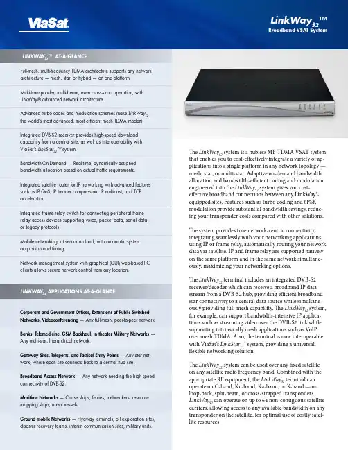
The LinkWay S2 system is a hubless MF-TDMA VSAT system that enables you to cost-effectively integrate a variety of ap-plications into a single platform in any network topology — mesh, star, or multi-star. Adaptive on-demand bandwidth allocation and bandwidth-efficient coding and modulation engineered into the LinkWay S2 system gives you cost-effective broadband connections between any LinkWay®-equipped sites. Features such as turbo coding and 8PSK modulation provide substantial bandwidth savings, reduc-ing your transponder costs compared with other solutions.The system provides true network-centric connectivity, integrating seamlessly with your networking applications using IP or frame relay, automatically routing your network data via satellite. IP and frame relay are supported natively on the same platform and in the same network simultane-ously, maximizing your networking options.The LinkWay S2 terminal includes an integrated DVB-S2 receiver/decoder which can receive a broadband IP data stream from a DVB-S2 hub, providing efficient broadband star connectivity to a central data source while simultane-ously providing full-mesh capability. The LinkWay S2 system, for example, can support bandwidth-intensive IP applica-tions such as streaming video over the DVB-S2 link while supporting intrinsically mesh applications such as VoIP over mesh TDMA. Also, the terminal is now interoperable with ViaSat’s LinkStar S2™ system, providing a universal, flexible networking solution.The LinkWay S2 system can be used over any fixed satellite on any satellite radio frequency band. Combined with the appropriate RF equipment, the LinkWay S2 terminal can operate on C-band, Ku-band, Ka-band, or X-band — on loop-back, split-beam, or cross-strapped transponders. LinkWay S2 can operate on up to 64 non-contiguous satellite carriers, allowing access to any available bandwidth on any transponder on the satellite, for optimal use of costly satel-lite resources.Full-mesh, multi-frequency TDMA architecture supports any network architecture — mesh, star, or hybrid — on one platform.Multi-transponder, multi-beam, even cross-strap operation, with LinkWay® advanced network architecture.Advanced turbo codes and modulation schemes make LinkWay S2 the world’s most advanced, most efficient mesh TDMA modem.Integrated DVB-S2 receiver provides high-speed download capability from a central site, as well as interoperability with ViaSat’s LinkStar S2™ system.Bandwidth-On-Demand — Real-time, dynamically-assigned bandwidth allocation based on actual traffic requirements.Integrated satellite router for IP networking with advanced features such as IP QoS, IP header compression, IP multicast, and TCP acceleration.Integrated frame relay switch for connecting peripheral frame relay access devices supporting voice, packet data, serial data,or legacy protocols.Mobile networking, at sea or on land, with automatic system acquisition and timing.Network management system with graphical (GUI) web-based PC clients allows secure network control from any location.LINKWAY S2 APPLICATIONS AT-A-GLANCECorporate and Government Offices, Extensions of Public Switched Networks, Videoconferencing — Any full-mesh, peer-to-peer network.Banks, Telemedicine, GSM Backhaul, In-theater Military Networks — Any multi-star, hierarchical network.Gateway Sites, Teleports, and Tactical Entry Points — Any star net-work, where each site connects back to a central hub site.Broadband Access Network — Any network needing the high-speed connectivity of DVB-S2.Maritime Networks — Cruise ships, ferries, icebreakers, resource mapping ships, naval vessels.Ground-mobile Networks — Flyaway terminals, oil exploration sites, disaster recovery teams, interim communication sites, military units.LINKWAY S2™ AT-A-GLANCELinkWay S2™Broadband VSAT SystemThe Most Advanced VSAT Networking TechnologyViaSat continues to offer the most innovative satellite network-ing products with its LinkWay S2 system. The LinkWay S2 termi-nal builds upon and expands the capabilities of the successful LINKWAY 2100, assuming the LINKWAY 2100’s place as the world’s most advanced mesh TDMA system.LinkWay S2 uses a revolutionary new mesh TDMA modem design. Turbo coding provides quasi-error-free connections with minimal carrier power requirements. 8PSK* modulation provides dramatically improved spectral efficiency. Combined with an improved, shorter TDMA preamble, LinkWay S2 is more efficient than convolutional-encoded Reed-Solomon systems, increasing throughput, reducing station size, and reducing satellite bandwidth requirements.The LinkWay S2 terminal provides choices of carrier rate from 312 Ksps to 5 Msps, enabling system operators to select the optimum carrier rate for their particular network traffic profile. With efficient TDMA operation at lower symbol rates, this terminal provides an excellent solution for low-throughput applications, such as voice. With carrier rates up to 5Msps, the LinkWay S2 also handles high-throughput applications, such as video or large media file transfers.Unique in the industry, the LinkWay S2 is a mesh MF-TDMA modem with completely independent fast-hopping transmit and receive sections. The transmit modulator and receive demodulator can each tune on a burst-to-burst basis, indepen-dently and automatically, to any of 64 carriers across an 800 MHz frequency range spanning multiple transponders, multiple carrier rates, multiple carrier coding rates, and multiple carrier modulations. This allows the most efficient allocation of band-width on the network carriers, on any available timeslot on any available carrier frequency, for the most flexible and frequency-agile system available.The LinkWay S2 DVB-S2 receiver, with EN 302 307-compliant coding, provides bandwidth-efficient broadband downloadcapability to the LINKWAY system. The DVB-S2 coding scheme is so advanced, it may represent the last major development in high-speed satellite modem design. With higher throughput at lower Eb/No than other systems, it enables broadband connec-tions into reduced size stations. Operators may use LinkWay S2 with a standard EN 302 307 DVB-S2 modulator and IP encapsu-lator or with ViaSat’s LinkStar S2 hub.LinkWay S2 Terminal DescriptionThe IDU (Indoor Unit) contains one integrated IP port and one integrated frame relay serial port.The terminal is designed for stand-alone operation, requiring no local operator control. Configuration and monitoring of remote sites is done over-the-air via the LINKWAY Network Management System (NMS), or via telnet. The IDU also in-cludes a console interface port for unit installation.The IDU features an extended 950-1750 MHz L-band interface to the radio frequency transceiver (RFT), for operation across multiple RF bands limited only by the capability of RFT. The built-in DVB-S2 receiver uses the same L-band receive interface as the TDMA mesh modem for a simple, clean design.The complete LinkWay S2 VSAT terminal includes an RFT con-sisting of C- or Ku-band radio equipment and an antenna. Typi-cal radio transmit powers are 2, 4, 8, and 16 Watts in Ku-band, and 5, 10, and 20 Watts in C-band.Typical antenna sizes are 1.2, 1.8, and 2.4 meter for Ku-band, with 1.8, 2.4, and 3.8 meter in C-band. The terminal can be deployed with a variety of RFT sizes throughout the network, with size based on the satellite parameters, station traffic re-quirements, and geographic location of network stations.LinkWay S2 Broadband VSAT System* OptionalLinkWayS2can also be used in a maritime or ground-mobile en-vironment on a stabilized platform. When combined with GPS,terminal acquisition, synchronization and timing are automaticeven when the terminal is in motion.The LinkWayS2terminal may be operated in a LINKWAY2100-compatible mode, for adding or replacing sites inan existing LINKWAY 2100 network, ensuring an operator’sinvestment in LINKWAY 2100 remains solid for years to come.Network Control and ManagementLinkWayS2terminals are controlled by a full-featured NetworkControl Center (NCC) workstation that manages TDMA net-work timing, synchronization, terminal acquisition, networkconfiguration, and bandwidth management. The NCC also actsas the NMS server. The NMS is a client-server system with aneasy-to-use Web-based graphical interface. With this approach,a PC-based remote NMS client can securely access the NCCserver from anywhere in the world.The NMS user windows make it simple to access key informa-tion. Network status, network station maps, system configura-tion, alarm status, circuit set-up, accounting, link performance,and diagnostic commands are available with the click of amouse.The NCC database files can be shared with other operationaltools such as billing systems, and the network may also bemonitored via SNMP. Multiple levels of access control ensurethat security is maintained.Satellite Network ArchitectureThe NCC is collocated with the Master Reference terminal(MRT). The MRT acts as a conduit for the NCC network controlmessages to the remote terminals, providing timing and signal-ing which enable over-the-satellite control of the network fromthe NCC and NMS. Any LinkWayS2terminal can be configuredto be the MRT — no special hub hardware is needed, reducingexpense and improving logistics.Local or geographic redundancy is provided for the NCC andMRT to ensure reliable network operation and provide auto-matic network recovery.Unique among TDMA systems, LINKWAY terminals do not allhave to be in the same satellite beam — i.e., the MRT does notrequire direct loop-back connectivity with itself or the remoteterminals. Advanced control algorithms allow multi-beam oreven cross-strapped network architectures using a SupportingReference Terminal (SRT).Multi-beam operation allows a single LinkWayS2network tospan across the entire footprint of all transponders’ single satel-lite — enabling transoceanic, transcontinental, and hemisphericnetworks. This makes LinkWayS2ideal for large, multinationalnetworks, such as embassy networks, international organizationnetworks, air traffic control networks, and military networks.LinkWay S2 Broadband VSAT SystemSPECIFICATIONSCopyright © 2008 ViaSat, Inc. All rights reserved. Printed in the USA. ViaSat, the ViaSat logo and LinkWay are registered trademarks of ViaSat, Inc. LinkStar S2 and LinkWay S2 are trademarks of ViaSat, Inc. All other trademarks mentioned are the sole property of their respective companies. Specifications and product availability are subject to change without notice.Atlanta 1725 Breckinridge Plaza, Duluth, GA 30096, Tel: +1.678.924.2400, Fax: +1.678.924.2480Beijing Lucky Tower, Block B, Suite 1112, No. 3 Dong San Huan Bei Lu, Beijing 100027, China, Tel: +86.10.6461.5761, Fax: +86.10.6461.5754New Delhi 601 New Delhi 611-A, JMD Pacific Square, Sector 15, Part 2, NH #8 Gurgaon 122001 Haryana India Tel: +91-124-402-5200, Fax: +91-124-402-5252Rome Piazza del Popolo 18, 00187 Rome, Italy, Tel: +39-0636712432, Fax: +39-0636712400San Diego 6155 El Camino Real, Carlsbad, CA 92009, Tel: +1.760.476.2200, Fax: +1.760.929.3941Sydney Unit 4/22 Narabang Way, Belrose, NSW 2085, Australia, Tel: +61.2.9986.3888, Fax: +61.2.9986.3899ViaSat, Inc.Tel: +1.678.924.2880Fax: +1.678.924.2480vsatsales@ MF-TDMA MODEMModulation: QPSK, 8PSK*Symbol Rates: 312.5Ksps to 2.5Msps; 5Msps*Forward Error Correction: Turbo Coding*FEC Rates: 1/2, 2/3, 3/4, 7/8DVB-S2 RECEIVER Modulation: QPSK, 8PSKSymbol Rates: 2.5Msps to 30MspsForward Error Correction: LDPC Turbo Coding per EN 302 307FEC Rates:QPSK: 1/2, 3/5, 2/3, 3/4, 4/5, 5/6, 8/9, 9/10 8PSK: 3/5, 2/3, 3/4, 5/6, 8/9, 9/10L-BAND INTERFACETx: F-type, 75 Ohm; 950-1750 MHz range Rx: F-type, 75 Ohm; 950-1750 MHz range PHYSICAL INTERFACES: IP and Frame Relay Expansion: 2 PMC interface slotsConsole Port: RS-232 electrical, RJ-11 physicalNETWORK INTERFACESIP: 10/100BT IEEE 802.2 Ethernet (RJ45)Frame Relay: SCSI-26pin synchronous serial interface, with transition cables to RS-449, RS-530, and V.35ENVIRONMENTAL Temperature Range:Operational: 0°C to +50°C; Storage: 0°C to +70°C Relative Humidity:Operational: 0 to 95%; Storage: 0 to 95% (non-condensing)ELECTRICALPower Supply: 50/60 Hz, Autorange 100-240VAC MECHANICALDimensions: (H x W x D)1.75 X 17 X 15 in. (4.45 x 43.2 x 38.1 cm)Weight: ~6 lb (~2.8 kg)OUTDOOR UNITSKu-Band Antennas: 1.2, 1.8, or 2.4 meter Ku-Band RFTs: 2, 4, or 16 WattC-Band Antennas: 1.8, 2.4, 3.8 meter C-Band RFTs: 5,10, or 20 Watt Interfacility Link: L-bandCertification: CE, FCC, R&TTE, ANATEL * OptionalAdvanced Internet Protocol NetworkingThe IP port of a LinkWay S2 terminal acts as an interface of a virtual satellite-based router. IP packets entering one LinkWay S2 terminal IP interface are automatically routed by IP address and transported to the destination LinkWay S2 terminal IP interface.Quality of service is maintained via differential services-compatible prioritization with six transmit queues. Onboard TCP acceleration removes satellite delay-induced throughput limits. Built-in IP header compression reduces bandwidth required for VoIP.The IP multicast feature enables one LinkWay S2 site to simultaneously communicate with multiple other Link-Way S2 sites — perfect for multi-party videoconferencing or distance learning.IPSec transparent, the LinkWay S2 terminal can be used with peripheral IP encryption devices.Advance Frame Relay NetworkingThe frame relay interface of a LinkWay S2 terminal acts as an interface of a virtual satellite-based frame relay switch. Frame relay frames entering one LinkWay S2 terminal inter-face are automatically switched by DLCI and transported to the destination LinkWay S2 terminal interface.LinkWay S2 supports both frame relay PVCs and SVCs.。

EverLink2000网管系统使用手册版本 V1.3目录1.EverLink2000网管系统简介 (4)2. 系统安装 (5)2.1 Windows系统上安装 (5)2.1.1 环境准备 (5)2.1.2 服务端安装前的检查 (6)2.1.3 服务端安装和运行 (7)2.1.4 从浏览器启动客户端 (7)2.1.5 手工运行客户端 (7)2.1.6 防火墙 (7)3. EverLink2000网管系统系统 (7)3.1 启动与登录 (7)3.1.1 启动数据库 (7)3.1.2 启动服务器 (8)3.1.3 启动客户端 (8)3.1.2.1 启动控制台 (8)3.1.2.2 登陆 (8)3.2 EverLink2000网管主视图 (9)3.2.1 菜单 (9)3.2.2 工具条 (9)3.2.3 功能树 (10)3.2.3 被管设备状态信息 (10)3.2.4 全网工作状态统计 (10)3.2.5 查看设备信息 (11)3.2.6 设备根视图 (11)3.2.7 文件菜单 (12)3.2.7.1 修改密码 (12)3.2.7.2 退出系统 (13)3.2.8 拓扑管理菜单 (13)3.2.8.1 转到根视图 (13)3.2.8.2 刷新全网拓扑图 (13)3.2.8.3 保存网络拓扑图 (13)3.2.8.4 添加网络 (14)3.2.9 故障管理菜单 (15)3.2.9.1 显示所有当前告警 (15)3.2.9.2 显示所有历史告警 (16)3.2.9.3 显示所有告警统计 (17)3.2.9.4 管理所有事件信息 (18)3.2.9.5 清除所有当前告警 (18)3.2.9.6 清除所有历史告警 (19)3.2.9.7 启用或禁用告警声音报警 (19)3.2.9.8 管理故障解决方案 (19)3.2.10 统计报表菜单 (20)3.2.10.1 全网故障个数最多设备 (20)3.2.10.2 全网故障个数最少设备 (20)3.2.10.3 全网故障率最高设备 (21)3.2.10.4 全网故障率最低设备 (21)3.2.10.5 全网经常发生的故障类型 (22)3.2.10.6 全网很少发生的故障类型 (22)3.2.10.7 全网信息统计 (22)3.2.10.8 查看全网设备 (23)3.2.10.9 全网MAC-IP列表 (23)3.2.10.10 设备侦测名单 (24)3.2.11 系统管理 (24)3.2.11.1 用户管理 (25)3.2.11.2 日志管理 (26)3.2.11.3 配置系统参数 (27)3.2.11.4 配置Syslog参数 (28)3.2.11.5 配置FTP参数 (28)3.2.11.6 配置TFTP参数 (29)3.2.12 帮助 (29)3.2.12.1 关于 (30)3.3 iSAP5100板卡信息及配置 (30)3.3.1 主控卡(MS-DM-155主控卡,MS-DM-96主控卡) (30)3.3.1.1 MS-DM-155主控卡 (30)3.3.1.2 MS-DM-96主控卡 (38)3.3.2 E1卡和Bert测试(16E1卡,8E1卡) (38)3.3.2.1 Bert测试 (39)3.3.3 FXO卡 (40)3.3.3.1 复用时隙 (42)3.3.4 FXS卡 (42)3.3.5 E&M卡 (43)3.3.6 G703卡 (44)3.3.7 RS232_C/RS232卡 (45)3.3.8 ET100卡 (47)3.4 网络、设备、资源管理 (48)3.4.1组织结构管理 (48)3.4.1.1 新建网络 (48)3.4.1.2、删除网络 (49)3.4.2设备管理 (49)3.4.2.1 IP范围自动发现 (50)3.4.2.2、网络号自动发现 (51)3.4.2.3 路由器IP自动发现 (52)3.4.2.4 漫游自动发现 (53)3.4.2.5 手工添加设备 (54)3.4.2.6 管理设备链接 (56)3.5 网络、设备、资源管理 (56)3.5.1拓扑图操作 (56)3.5.1.1移动网络/设备/资源位置 (56)3.5.1.2保存网络/设备/资源位置 (57)3.5.1.3刷新全网拓扑图 (57)3.5.1.4刷新本网络 (57)1.EverLink2000网管系统简介EverLink2000是面向客户的接入网综合管理系统,是由北京恒光创新科技股份有限公司自主开发,用于满足边缘接入网网管需求,遵循Internet/SNMP管理体系结构。

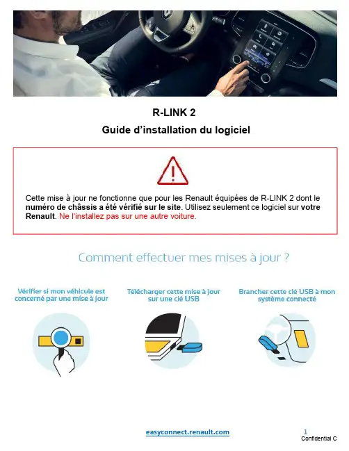
R-LINK 2Guide d’installation du logicielCette mise à jour ne fonctionne que pour les Renault équipées de R-LINK 2 dont le numéro de châssis a été vérifié sur le site . Utilisez seulement ce logiciel sur votre Renault . Ne l’installez pas sur une autre voiture.Pré-requis A : Notez votre numéro de châssisVous pouvez retrouver ce numéro dans votre Renault ou sur votre carte grise emplacement E. Ce numéro est obligatoire pour vérifier que la mise à jour est compatible avec votre Renault. Ce numéro de châssis commence par VF et comporte 17 caractères sans "i" ni "o".Pré-requis B : utilisez une clé USB au format FAT 32 (8GB-32 GB)Pour vérifier que votre clé est au format FAT 32 allez dans l’onglet propriétés de la clé (exemple clic droit sur PC)Pour dézipper le fichier à télécharger, nous vous recommandons d’utiliser 7-Zip (vous pouvez le télécharger sur http://7zip.fr/). N’oubliez pas de vérifier que votre connexion internet est active pendant toute la procédure.Et surtout n’interrompez pas un téléchargement en cours.Etape 1 : Téléchargez la mise à jour logicielleEcran d’exemple. La version porte le numéro indiqué au moment du téléchargement.Etape 2 : Dézippez le fichierDézippez avec 7-Zip en utilisant la commande “Extraire”. Puis copiez le dossier R-LINK à la racine de la clé USB. Ne modifiez pas le dossier R-LINK. Ne le renommez pas. Ne ledéplacez pas non plus dans un autre emplacement.Etape 3 : Installez le fichier sur votre cléLe dossier peut contenir plusieurs fichiers. Vous pouvez ouvrir le dossier R-LINK uniquement pour vérifier que le fichier logiciel a été correctement copié.Etape 4 : Installez la mise à jour sur votre R-LINK 2 1/2Démarrez le moteur et votre R-LINK 2. Branchez votre clé USB. Votre R-LINK 2 détecte automatiquement la mise à jour sur votre clé (patientez 3 minutes). N’éteignez pas le moteur pendant l’installation. L’installation peut prendre jusqu’à 10 minutes.Ensuite, votre R-LINK 2 sera noir pendant l’installation. Votre camera et radar de recul seront aussi indisponibles. Votre R-LINK 2 redémarrera plusieurs fois. Ne retirez pas la clé USB. Pour finir, un message à l’écran vous confirmera que l’installation est terminée. R-LINK 2 vérifie le fichier automatiquement. Puis les écrans ci-dessous se succèdent. Vous devez choisir “oui” sur tous ces écrans pour que l’installation démarre.Etape 4 : Installez la mise à jour sur votre R-LINK 2 2/2L’installation de la mise à jour pour votre R-LINK 2 effacera vos favoris de navigation ainsi que votre historique de trajets.Vous pouvez retirer la clé USBDernières vérificationsN’oubliez pas de contrôler que la connectivité de votre R-LINK 2 est active pour bénéficier de l’info Trafic en temps réel.Allez dans le menu principal. Si le bouton « Connecter » est présent (voir exemple ci-dessous) cela signifie que la carte SIM dans votre R-LINK 2 n’est pas activée. Suivez les instructions ci-dessous pour le faire.Appuyez sur le bouton “Connecter”. Acceptez le partage de données pour activer la connectivité à bord (remplissez votre adresse email -optionnel)L’activation peut prendre jusqu’à 72 heures.Vous pouvez vérifier si la mise à jour logicielles’est correctement déroulée en allant dans Menu->Système->Information Système. Ecran d’exemple. La version porte le numéro indiquéau moment du téléchargement.。
Before UseDigital Flow SwitchPF3A703H/PF3A706H/PF3A712H-LSafety InstructionsThese safety instructions are intended to prevent hazardous situations and/orequipment damage.These instructions indicate the level of potential hazard with the labels of"Caution", "Warning" or "Danger". They are all important notes for safety and mustbe followed in addition to International standards (ISO/IEC) and other safetyregulations.OperatorThank you for purchasing an SMC PF3A703H/PF3A706H/PF3A712H-L DigitalFlow Switch.Please read this manual carefully before operating the product and make sure youunderstand its capabilities and limitations. Please keep this manual handy forfuture reference.Safety Instructions1324DisplayBody(IN side)Connector pin numbers(on the product)Mounting•Never mount the product in a place that will be used as a mechanical support during piping.•Never mount the product upside down.•Attach the piping so that the fluid flows in the direction indicated by the arrow on the body.•The monitor with integrated display can be rotated.Rotating the display with excessive force will damage the end stop.•Visibility decreases if the display is viewed from the opposite side to the buttons.Check the settings and display from in front of the display.Mounting and InstallationRefer to the product catalogue or SMC website (URL https://) for moredetailed information.IN OUTArrowthe IN side of the product.When installing a regulator at the IN side of the product, make sure that hunting is not generated.•The piping on the IN side must have a straight section of piping whose length is 8 timesthe piping diameter or more.If a straight section of piping is not installed, the accuracy will vary by approximately 3%F.S.•Avoid sudden changes to the pipingsize on the IN side of the product.The accuracy may vary.•Do not release the OUT side pipingport of the product directly to theThe accuracy may vary.○Flow direction○Rotation of the display•Use the correct tightening torque for piping. (Refer to the table below for the requiredtorque values.)•If the tightening torque is exceeded, the product can be damaged.If the tightening torque is insufficient, the fittings may become loose.•Avoid any sealing tape getting inside the fluid passage.•Ensure there is no leakage after piping.•When mounting the fitting, a spanner should be used on the body (metal part) of thefitting only.Holding other parts of the product with a spanner may damage the product.Specifically, make sure that the spanner does not damage the M12 connector.■WiringConnection•Connections should only be made with the power supply turned off.•Use a separate route for the product wiring and any power or high voltage wiring. If wiresand cables are routed together with power or high voltage cables, malfunction may resultdue to noise.•If a commercially available switching power supply is used, be sure to ground the frameground (FG) terminal. If the product is connected to the commercially available switchingpower supply, switching noise will be superimposed and the product specifications will notbe satisfied. In that case, insert a noise filter such as a line noise filter/ ferrite between theswitching power supplies or change the switching power supply to the series power supply.Connecting/Disconnecting•Align the lead wire connector with the connector keygroove, and insert it straight in. Turn the knurled partclockwise. Connection is complete when the knurledpart is fully tightened. Check that the connection is notloose.•To remove the connector, loosen the knurled part andpull the connector straight out.Connector pin numbers (lead wire)Outline of SettingsPower is supplied.∗: If a button operation is not performed for 3 seconds during the setting, the display will flash. (This is toprevent the setting from remaining incomplete if, for instance, an operator were to leave during setting.)∗: 3 step setting mode, simple setting mode and function selection mode settings will reflect on each other.■3 step setting modeIn the3 step setting mode, the set value selected in the sub display and the hysteresiscan be changed in just 3 steps.Switch ONP_1Flow[L/min]H_1settingsWhen shipped, the default setting is as follows.When the flow exceeds the set value [P_1], the switch will be turned ON.When the flow falls below the set value by the amount of hysteresis [H_1] or more, theswitch will turn OFF.If the operation shown below is acceptable, then keep these settings.For more detailed settings, set each function in the function selection mode.(1) Press the S button once when the item to be changed is displayed on the subdisplay.The set value on the sub display (right) will start flashing.S<Operation>[Hysteresis mode]In the 3 step setting mode, the set value (P_1 or n_1) and hysteresis (H_1) can bechanged.Set the items on the sub display (set value and hysteresis) using the ▲ or ▼ buttons.When changing the set value, follow the operation below. The hysteresis setting can bechanged in the same way.(2) Press the ▲ or ▼ button to change the set value.The ▲ button is to increase and the ▼ button is to decrease the set value.●Press the ▲ button once to increase the value by one digit, press and hold tocontinuously increase.●When ▲ and ▼ buttons are pressed simultaneously for 1 second or more, the setvalue is displayed as [ - - - ], and the set value will be set to the same as thedisplayed value automatically. Afterwards, it is possible to adjust the value bypressing ▲ or ▼.●Press the ▼ button once to reduce the value by one digit, press and hold tocontinuously reduce.(3) Press the S button to complete the setting.To change setting, refer to the operation manual from SMC website(URL https://) or contact SMC.<Operation>[Hysteresis mode](1) Press the S button for 1 second or longer(but less than 3 seconds) in measurementmode. [SEt] is displayed on the main display.When the button is released while in the [SEt] display, the current flow value isdisplayed on the main display, [P_1] or [n_1] is displayed on the sub display (left)and the set value is displayed on the sub display (right).(2) Change the set value using the ▲ or ▼ button, and press the SET button to set thevalue. Then, the setting moves to hysteresis setting.(5) Press and hold the S button for 2 seconds or longer to complete the simple setting.(If the button is pressed for less than 2 seconds, the setting will be returned to P_1.)(3) Change the set value with the ▲ or ▼ button, and press the S button to set thevalue. Then, the setting moves to the setting of OUT2.∗1: Selected items of (1) to (4) become valid after pressing the S button.∗2: After enabling the setting by pressing the S button, it is possible to return to measurementmode by pressing the S button for 2 seconds or longer.∗3: When the output mode is set to accumulated pulse, error output or output OFF, the simplesetting mode cannot be used.(the setting returns to measurement mode by releasing the button when [SEt] is displayed.)■Simple setting modeIn the simple setting mode, the set value, hysteresis and delay time can be changed whilechecking the current flow value (main display).(4) Like the setting of OUT1, the setting returns to the setting of OUT2 by pressing theS button after setting the set value and hysteresis.∗: When [F 1] and [F 2] are set to accumulatedpulse output, error output or output OFF [---]will be displayed in the sub screen when[SEt] is displayed. It is not possible to moveto the Simple setting mode.Change the Function Settings∗1: Setting is only possible for models with the units selection function.∗2: [F 2] The OUT2 setting can be set on the product screen, but since there is no OUT2 switch outputfunction as an output specification, it is not possible to output the ON/OFF signal to an external device.∗3: When the 1 switch output type (output specification symbol is L) is used, [F5] is displayed as [---]and cannot be set.1 to 5 V or 0 to 10 V can be selected when the analogue voltage output type is used.Analogue output free range function can be selected.∗4: When Line name is selected, a suitable line name can be input.To change setting, refer to the operation manual from SMC website(URL https://) or contact SMC.■Function selection modeIn measurement mode, press theS button for 3 seconds or longer,to display [F 0].The [F] indicates the mode forchanging each Function Setting.Press the S button for 2 secondsor longer in function selectionmode to return to measurementmode.To change setting, refer to the operation manual from SMC website(URL https://) or contact SMC.○Reset operationThe Accumulated Flow, Peak Value and Bottom Value can be reset.To reset the accumulated value, press the ▼ and S button for 1 second or longer.○Snap shot functionThe current flow rate value can be stored to the switch output ON/OFF set point.When the items on the Sub display (left) are selected in either 3 step setting mode, Simplesetting mode or Setting of each function mode, by pressing the ▲ and ▼ buttonssimultaneously for 1 second or longer, the value of the sub display (right) will show "----",and the values corresponding to the current flow rate are automatically displayed.MaintenanceHow to reset the product after a power loss or when the power has beenunexpectedly removedThe settings for the product are retained in memory prior to the power loss or de-energizingof the product.The output condition is also recoverable to that prior to the power loss or de-energizing.However, this may change depending on the operating environment. Therefore, check thesafety of the whole installation before operating the product.If the installation is using accurate control, wait until the product has warmed up(approximately 10 to 15 minutes) before operation.Refer to the product catalogue or operation manual from SMC website(URL https://) for more information about the product specifications anddimensions.Specifications / Dimensions○Key-lock function(1) Press the S button for 5 seconds or longer in measurement mode. When [oPE] isdisplayed on the main display, release the button.The current setting "LoC" or "UnLoC" will be displayed on the sub display.(2) Select the key locking/un-locking using the ▲ or ▼ button, and press the S button toset.To use each of these functions, refer to the operation manual from SMC website(URL https://) or contact SMC.The IODD file can be downloaded from the SMC website (URL https://).Note: Specifications are subject to change without prior notice and any obligation on the part of the manufacturer.© 2020 SMC Corporation All Rights ReservedAkihabara UDX 15F, 4-14-1, Sotokanda, Chiyoda-ku, Tokyo 101-0021, JAPANPhone: +81 3-5207-8249 Fax: +81 3-5298-5362URL https://PF※※-OMX0003Troubleshootingdisplayed, please contact SMC.Refer to the operation manual from SMC website (URL https://) for moreinformation about troubleshooting.。

1IntroductionIn this manual we’ll explain the steps needed to take to link your Magento 2 webshop to the payment methods of Pay.In order to use this plugin, you’ll need a Pay. account. If you don’t have an account yet, use the following link to register https://www.pay.nl/en/register-now.ContactWhen you run into problems installing or configuring the plugin, please contact us using the following information:Pay. SupportT +31 (0) 88 886 6666E**************Magento SupportW https://support2In My.pay (admin portal)Go to https://www.pay.nl/en/ and login with your email address and password. In the menu go to “Settings” > “Sales locationsAdd the serviceIn the next page, you’ll find your websites. If your Magento website is already listed here, you can skip this step.On the bottom right, click “add”On the next page, some information about your website is asked. Try to select the category that best fits your website. The red circled fields are important when you’re using the Magento 2 plugin, use the same values as in the screenshot below.Enabling payment methodsEnable the checkboxes for each payment method that you want to use. Payment methods that are not enabled here cannot be enabled in Magento.Other settingsAfter selecting the payment methods, you can setup “Exchange settings” or also called “Communications URL”. The plugin will work with the standard settings, but when something goeswrong in the communication between Pay. and your webshop, we will not retry.The advised settings for communication URLDo you want to receive a notification of all successful payments? This is possible. Just activate our notification service. From now on you will receive a notification after a successful transaction.API token and Service-IDThe plugin uses the:•AT-code (account code)•API token•SL-code (sales location)to connect to your Pay. account. To get your credentials, go to “Settings” > “Sales location” and click on “Info”.In the pop-up the AT-code, API token and SL-code are shown.We are going to use this API token and Service-ID in the next chapter.3. In the Magento 2 adminAfter you’ve installed the plugin, it still needs to be configured. On the bottom left, click “Stores” and in the menu click “Configuration”. Now go to “Pay.”.Configure your credentials (AT-code, API token and SL-code) by going to “Setup” in the Pay. menu. Fill in:•AT-code in Tokencode•API token•SL-code in ServiceIdEnabling the payment methodsOpen the submenu “Payment settings” in the Pay. menu and open the payment method that you want to enable. Set the setting enabled to “Yes” so the settings for the payment method are shown.Here you can set the settings for the payment method. If you can’t enable a payment method in Magento2, make sure it is enabled in My.pay.With credit cards it can take a few days after starting the boarding process, before you can enable the payment method in Magento.When you have set up all payment methods, click “Save Config”.You are now ready to receive payments in your webshop!Enschede office Kopersteden 10 7547 TK Enschede Amsterdam officeDalsteindreef 1411112 XJ DiemenSpijkenisse officeCurieweg 193208 KJ SpijkenisseSales & Care+31(0)88-88 666 66 Support: ************** Sales: ************Availability MON-FRI: 09:00 – 17:30。
ULINK2用户指南Table Of Contents1. 概述 (2)1.1 工具包 (2)1.2 特性 (3)1.3 支持的设备 (3)1.4 支持的协议 (4)1.5 软件需求 (5)1.6 局限性 (5)1.7 技术参数 (5)2. 硬件描述 (6)2.1 USB 接口 (6)2.2 LED 指示灯 (7)2.3 跳线 (7)2.4 目标连接器 (8)2.5 JTAG 接口电路图 (10)2.6 启动顺序 (12)2.7 重启顺序 (12)3. 安装及使用 ULINK2 (13)3.1 连接 ULINK2 (14)3.2 安装驱动 (14)3.3 配置μVision (15)3.3.1 调试驱动配置 (15)3.3.2 设置Flash 下载 (18)3.4 下载到 Flash (27)3.5 调试程序 (28)3.6 链接多目标 (28)4. 实时代理 (30)4.1 添加实时代理 (30)4.1.1 给工程添加 RTA 文件 (31)4.1.2 配置实时代理 (31)4.1.3 修改 STARTUP.S 文件 (32)4.1.4 测试实时代理 (33)4.2 添加 I/O 重定向 (34)4.2.1 添加 RETARGET.C (34)4.2.2 配置 RETARGET.C (34)4.2.3 测试重定向 (36)4.3 API 函数 (36)4.4 接口自定义硬件 (37)5. Addenda (38)5.1 ULINK2: Configuring the Real-Time Agent (38)1. 概述概述Keil ULINK2 USB-JTAG 适*配器通过USB 端口将*PC机与目标硬件(经JTAG 或 OCDS)连接起来,可以实现:•下载程序到目标硬件上进行测试;•对许多设备(See 1.3) 的片上 FLASH 存储器进行编程;•对许多目标系统的外部 FLASH 存储器进行编程。
New R-LINK 2S oftware upgrade installation guideThis upgrade is only compatible with Renault vehicles equipped with R-LINK 2 multimedia systems where the VIN number has been verified on the multimedia website. Use the software only on this specific Renault. Do not install it on another car.Before you start: Get your VIN number readyYou can find your VIN number in your car or on your V5 car registration document. This information is mandatory to check if the software upgrade is available for your Renault vehicle. Please check the number. It must begin with VF and include 17 digits without any letters "i" nor "o".Before you start: Find a USB stick in FAT 32 format (8GB-32 GB)To check if your USB stick is in FAT 32 format access its properties (example: right click on PC/ properties).Make sure that your internet connection is active during the whole process.Please do not interrupt the download whilst it is in progress.Step 1: Download the softwareExample screen. The version’s number is indicated at the time of the download.Step 2: Unzip the fileUnzip and “Extract” the file you have downloaded. You can use 7-zip (/) to do this. Then copy the R-LINK folder onto the USB key at the root. Keep the R-LINK folder exactly as it is. Do not rename the folder nor install the software in another location on the USB stick.Step 3: View the downloaded file on your USB stickThe folder may contain several files. You can open the folder to check the software has been correctly copied.Step 4: Install the software on your R-LINK 2 1/2Switch on the engine and your R-LINK 2 system. Plug in your USB stick. The software on your USB stick will be automatically detected after 3 minutes. Please keep the engine running while the software installs. It can take up to 10 minutes.R-LINK 2 will automaticallycheck the file integrity. Thenthe following screens will bedisplayed. Choose “Yes”for all screens to begin theinstallation process.The screen will be black for afew minutes during theinstallation process.The R-LINK 2 system mayrestart several times duringthe procedure. Rear cameraand parking aid sensor willneither be available. Do notunplug the USB. Amessage on the R-LINK 2will confirm that theinstallation is successful.Step 4: Install the software on your R-LINK 2 2/2You can now remove the USB stick.Note that the installation of the new R-LINK 2 software will reset your navigationfavorites and navigation history.Final CheckYou can double check if the software hasInstalled correctly Menu->System->SystemInformation. Example screen. The version’s numberis indicated at the time of the downloadDo not forget to check if your R-LINK 2 system has the connectivity activated for LIVE Info TrafficPlease go to main menu on your R-LINK 2 and check if the connect button isshowing. If connect button showing, follow the instructions below.Press the “Connect” button. Accept thedifferent conditions to allow connectivity(you can also fill in your email address(optional).The activation may take up to 72 hours.。
本产品符合适用的 CE 要求。
组装手册/用户手册重要安全说明 3安全警告标签和序列号 5规格 6组装准备 6部件 7零件8工具8组装9调平健身车15移动健身车15功能16紧急停止 16控制面板功能 16操作 18调整 18锻炼模式 19暂停或停止 19服务模式 20维护 21链条润滑 21更换控制面板电池 21故障排除 23为了获得保修支持资格,请保留原始购买凭证并记录以下信息:序列号 __________________________购买日期 ____________________要注册产品质保,请联系当地经销商。
如果您对产品存有疑问,请联系当地 Schwinn 经销商。
如需查找当地经销商,请转至:或Nautilus, Inc. 网站: | Nautilus, Inc. 地址:18225 NE Riverside Parkway, Portland, OR 97230 USA | 中国印刷 | © 2014 Nautilus, Inc. | ® 表示在美国注册的商标。
这些商标可能已在其他国家注册或以其他方式受普通法保护。
Schwinn、Schwinn Quality 徽标、Schwinn IC2、Bowflex、Nautilus 和 Universal 是归 Nautilus, Inc. 所有的商标或授权给 Nautilus, Inc. 使用的商标。
原版手册 - 仅英文版本23此图标表示存在潜在危险情况,如果不避免这种情况,则可能导致死亡或重伤。
请遵守以下警告:阅读并理解本机上的所有警告。
仔细阅读并理解组装说明。
•组装本机时,请始终不要让旁观者和儿童靠近本机。
•除明确指示之外,请勿将电池安装到本机上。
•请勿在户外或潮湿位置组装本机。
•确保在远离人流和旁观者的适当工作位置完成组装。
•本机的有些部件可能很笨重。
当执行涉及这些部件的组装步骤时,另需一人帮助。
请勿独自一人执行涉及笨重提举动作或困难动作的步骤。
Quick Start Guide This is only a quick start guide.A full wiring and installation manual is included in PCLink.Wire DescriptionInstaller ConnectionTypical ApplicationTrigger 1Crank Angle SensorReluctor, Proximity, Optical or HallTrigger 2Analogue Temp Input 1NTC Termistor sensors onlyTemp 1 & 2 have selectable / no pullupsAnalogue Temp Input 2Analogue Temp Input 3Analogue Volt 10-5V Input from sensor or external controller Analogue Volt 2Analogue Volt 3Analogue Volt 4Analogue Volt 5Analogue Volt 6Analogue Volt 7Analogue Volt 8+5V Out TPS and MAP sensor power+5V Power OUT +8V Out +8V Power OUTIgnition 1Use spare Ignition channels for switching type Auxillary OutputsIgnition 2Ignition 3Ignition 4Ignition 5Ignition 6Ignition 7Ignition 8Installer I/O TableInjection 1Wire Inj 1 to cyl 1, 2 to 2, 3 to 3, etc...Use spare Injection channels for switching type Auxillary OutputsInjection 2Injection 3Injection 4Injection 5Injection 6Injection 7Injection 8Auxillary Output 1High Frequency PWM or VVT ControlThree Wire ISC Solenoid must be wired to Aux1 and Aux2Flywheeled, Low side onlyAuxillary Output 2Auxillary Output 3Auxillary Output 4Auxillary Output 5PWM less than 300 Hz or general switching functions Flywheeled, High / Low side Drives ISC Stepper (4 or 6 terminal)Auxillary Output 6Auxillary Output 7Auxillary Output 8Knock 1Knock Sensors OnlyKnock 2Digital Input 1Frequency Input, Switch Input or VVT Position Digital Input 2Digital Input 3Digital Input 4Digital Input 5Frequency Input or Switch InputDigital Input 6Digital Input 7Digital Input 8Wiring InformationIt is recommended that your Link G4+ Storm ECU is installed by a trained professional. Incorrect installation can result in damage to the ECU or the vehicle — extreme care must be taken.The following pin diagram shows the inputs and outputs available with the G4+ Storm ECUs. Application wiring examples are provided in the full Wiring and Installation Manual available in PCLink G4+.It is recommended that the installer fills out the ‘Installer I/O Table’ as a reference to keep with the ECU. This table is provided on the previous pages.A LOOMViewed looking into wire side of loomconnector (or into ECU header)A &B CONNECTOR KEYSBAIMPORTANT INFORMATIONG4+ ECUS ARE SHIPPED LOCKEDG4+ ECUs are shipped as locked and must be enabled before they are used. The ECU can be installed and configured using PCLink, but will not read engine RPM or run the engine until unlocked. Contact your ECU supplier to obtain an unlock code.SUPPORT OPTIONS• PCLink G4+ help — press F1 while running PCLink G4+. Includes help on wiring, PCLink G4+ and ECU functions• Contact your nearest Link dealer. A Link dealer list is available on • Link website: • TechnicalSupportemail:****************• Online Discussion Forum: /forumsMost questions received by the technical support team are answered in the PCLink G4+ Help section. Please consult the manuals to make sure that your question has not already been answered.PCLINK G4+All Link G4+ ECUs are tuned and configured by our PCLink G4+ software package. Connection to the ECU is established through on-board USB.The latest version of PCLink G4+ can be downloaded from . Included with PCLink G4+ are the USB drivers for connecting to the ECU.IMPORTANTBefore connecting the ECU to your PC, the correct USB drivers must be installed.Failure to install the drivers on your PC first may result in Windows assigning incorrect drivers. These drivers will not work with the ECU and are difficult to uninstall.After installation, consult PCLink G4+ Help (press F1) for instructions on connecting to the ECU. Once you have the ECU connected to PCLink, check the ECU firmware and upgrade to the latest version if it is not already.GENERAL ECU MOUNTING GUIDELINESThe following requirements should be taken into account during the installation of the ECU:continued on next page• The ECU should be fitted inside the vehicle cabin in a location that avoids exposure to excessive temperatures and the risk of water ingress. The location of the ECU should also be physically separated from the ignition components or any other components that may cause interference.• Allow enough room at both ends of the ECU for the main wiring harness and tuning cables to be connected.• The mounting bracket provided should be installed on a flat surface, with the ECU firmly fitted to the bracket. Alternative brackets should not be used and under no circumstances should holes be drilled in the ECU case. Any modifications to the case will render the warranty invalid and may cause internal damage.• It is recommended that the ECU is rubber mounted in order to isolate the ECU from vibration.• For motorsport applications, the ECU should be located in a position that minimises the risk of physical damage in the event of the vehicle being involved in a crash. ECUs used for speedway applications should be mounted securely within the cockpit area, protected from the elements, isolated from vibration and utilise an additional retention strap for protection from high impacts. Please refer to the Wiring Information section in PCLink G4+ help for additional information.LIFETIME WARRANTYLINK ENGINE MANAGEMENT LTD - LIMITED LIFETIME WARRANTYAll Engine Control Units (ECUs) manufactured or distributed by LINK Engine Management Ltd are subject to the following LIMITED LIFETIME WARRANTIES, and no others.LINK Engine Management Ltd warrants only to the original purchaser of the ECU, for the lifetime of the ECU, (subject to the limitations set out below), that the ECU shall be free from defects of materials and workmanship in the manufacturing process. This warranty ceases to apply and does not apply to ECUs that have not been manufactured or distributed by LINK Engine Management Ltd for a period of greater than one year.An ECU claimed to be defective must be returned to the place of purchase. LINK Engine Management Ltd, at its sole option, may replace the defective ECU with a comparable new ECU or repair the defective ECU.This limited lifetime warranty is not transferrable and does not apply to any ECU not properly installed or properly used by the purchaser or end user, or to any ECU damaged or impaired by external forces. The above warranties are the full extent of the warranties available on the ECU. LINK Engine Management Ltd has no liability to the original purchaser or any other person for any loss, injury or damage to persons or property resulting from the use of the ECU or any failure of or defect in the ECU whetherby general, special, direct, indirect, incidental, consequential, exemplary, punitive, or any other damages of any kind or nature whatsoever. LINK Engine Management Ltd specifically disclaims and disavows all other warranties, express or implied, including, without limitation, all warranties of fitness for a particular purpose, warranties of description, warranties of merchantability, trade usage or warranties of trade usage.For off-road use only. Not intended for highway vehicles. This ECU contains a user-configurable software programme, which is updated by LINK Engine Management Ltd from time to time. The user must ensure the current correct version of this programme is downloaded from the website of LINK Engine Management Ltd and installed in the ECU prior to use.This limited lifetime warranty does not apply where the ECU has been installed with the incorrect version of the software programme. The user is solely responsible for the setup and testing of all user-configurable features.LINK ENGINE MANAGEMENT LTD LICENSE AGREEMENTThe software programme in this ECU is licensed not sold. LINK Engine Management Ltd grants the user a license for the programme only in the country where the programme was acquired. No other rights are granted under this license and the programme may only be used on one machine at a time. If the programme is transferred a copy of this license and all other documentation must be transferred at the same time. The license may be terminated by the user at any time. LINK Engine Management Ltd may terminate the license if the user fails to comply with the terms and conditions of this license. In either event the copy of the programme must be destroyed.©2016 LINK Engine Management Ltd。