费加罗可燃气体传感器
- 格式:pdf
- 大小:119.38 KB
- 文档页数:2
费加罗气体传感器广州南创陈工FIGARO是一家专业生产半导体气体传感器的公司,1962年发明全球第一款半导体产品,目前全球第一。
FIGARO的产品远销38个国家,在多个国家设立了分支机构或办事处,生产基地遍布美洲、东欧、中国等地;并在中国设立了广州南创传感器事业部,可为用户的实验和生产提供最佳的服务与解决方案。
半导体气体传感器采用金属氧化物半导体烧结工艺,对被检测的检测气体具有灵敏度高、响应时间短、成本低、长期稳定性好等优点。
我们的产品包括可燃气体、有毒气体、空气质量、一氧化碳、二氧化碳、氨气、汽车尾气、酒精等传感器元件、传感模块等,以及各种气体传感器的配套产品。
目前已经被广泛应用于家用燃气报警器、工业有毒气体报警器、空气清新机、换气空调、空气质量控制、汽车尾气检测、蔬菜大棚、酒精检测、孵化机械等。
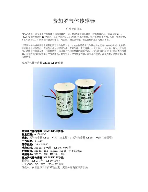
费加罗气体传感器KE-25 KE-50信息费加罗气体传感器KE-25 KE-50性能:测量范围:0-100%O2精度:氧气传感器KE-25:±1%(全量程);氧气传感器KE-50:±2%(全量程)工作温度:5~40℃储存温度:-20~+60℃响应时间:KE-25:14±2秒;KE-50:60±5秒初始输出:KE-25:10.0–15.5mv;KE-50:47.0-65.0mv期望寿命:KE-25:5年;KE-50:10年费加罗气体传感器KE-25 KE-50特性:长寿命(KE-25-5年,KE-50-10年)不受CO2,CO,H2S,NOx,H2影响低成本,在常温下工作信号输出定,无需外部电源不需加热以上费加罗气体传感器技术参数以《OIML60号国际建议》92年版为基础,最新具体变化可查看《JJG669—12FIGARO广州南创传感器事业部检定规程》产品特性描述:氧气传感器KE-25 KE-50属于半导体气体传感器不受CO2,CO,H2S,NOx,H2影响,氧气传感器KE-25 KE-50低成本在常温下工作信号输出定,无需外部电源不需加热;精度氧气传感器KE-25:±1%(全量程);氧气传感器KE-50:±2%(全量程)。
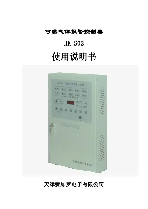
可燃气体报警控制器JK-S02使用说明书天津费加罗电子有限公司20030530目录产品使用须知.....................................1一、概述............................................2二、产品规格..........................................3三、面板各部名称及功能................................3四、控制器结构说明..................................5五、接线..............................................5六、操作方法......................................... 6七、注意事项..........................................7产品使用须知在使用本产品之前,请仔细阅读本说明书,以便正确使用。
◎本产品的使用只满足下列规定,避免此外的使用方法。
控制器(JK-S02):室内用可燃气体报警控制器国家消防电子产品质量监督检验中心测试合格探测器(BAT51-1、BAT51-2防爆型):防爆结构国家消防电子产品质量监督检验中心测试合格探测器(Ba-534b非防爆型):国家消防电子产品质量监督检验中心测试合格◎请实施定期点检根据本产品的设置的周围状况与环境,为确保安全,请实施定期点检。
点检周期:1-3个月点检方法:用点检气或监视气体对探测器进行动作点检点检测试项目:输出、声、光◎本产品的安装须由专业人员(有资格者)实施,严禁不按照使用说明书的要求安装、使用,及分解、改造等。
◎本产品符合中国国家标准GB16808-1997,只限中国境内使用。
感谢您使用天津费加罗电子有限公司的可燃气体报警控制器。
万一发生燃气泄漏,则有火灾、爆炸的危险。
天津费加罗可燃⽓体报警器技术⼿册第8章天津费加罗可燃⽓体报警器本公司推荐使⽤的费加罗可燃⽓体报警器有开关量和模拟量两种型号。
对没有特别指定的⽤户,我们推荐使⽤开关量输出的BA T51-2;对有特别要求的⽤户,我们提供4~20mA 输出的TC-F02。
⼀.摘要费加罗可燃⽓体探测器采⽤TGS813传感器。
该传感器对较宽范围的可燃⽓体都⽐较灵敏;尤其对甲烷、丙烷、异丁烷的灵敏度很⾼;它具有长寿命、低成本的特点;⽽且仅以简单电路即可使⽤。
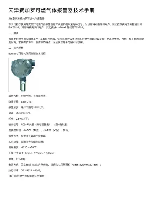
⼆.技术规格BAT51-2可燃⽓体探测器技术指标适⽤⽓种:可燃⽓体、有机溶剂等;防爆等级:ExdⅡCT6;报警浓度:爆炸下限的25%以下;电源:DC24V±15%;耗电:2.5VA以下;输出信号:R型=开关量(继电器输出)、V型=模拟量;连接控制器:JK-S02(R型)、JK-P06(V型)、其他;报警⽅式:报警信号输出给控制器;其它功能:故障信号传给控制器;使⽤温度:-40℃~+70℃;外型尺⼨:W 117mm×H 173mm×D 102mm;重量:约1200g;安装⽅式:固定⽀架(如在户外安装,请选购专⽤防⾬箱170mm×120mm×201mm);执⾏标准:GB 15322.x-2003。
TC-F02可燃⽓体探测器技术指标适⽤⽓种:可燃⽓体、有机溶剂等;防爆等级:ExdⅡCT6;报警浓度:爆炸下限的25%以下;电源:DC24V±15%;耗电:2.5VA以下;输出信号:4~20mA恒流输出(或1~5V);显⽰量程:爆炸下限的0~50%以下;消耗功率:2.5VA以下;负载能⼒:0~900Ω;使⽤温度:-40℃~+70℃;重量:约1600g;安装⽅式:固定⽀架(如在户外安装,请选购专⽤防⾬箱170mm×120mm×201mm);执⾏标准:GB 15322.x-2003。
TGS813传感器技术指标费加罗⽓体传感器的⽓敏素⼦,使⽤在清洁空⽓中电导率低的⼆氧化锡(SnO2)。
日本费加罗Figaro氧气传感器广州南创陈工FIGARO是一家专业生产半导体气体传感器的公司,1962年发明全球第一款半导体产品,目前全球第一。
FIGARO的产品远销38个国家,在多个国家设立了分支机构或办事处,生产基地遍布美洲、东欧、中国等地;并在中国设立了广州南创传感器事业部,可为用户的实验和生产提供最佳的服务与解决方案。
半导体气体传感器采用金属氧化物半导体烧结工艺,对被检测的检测气体具有灵敏度高、响应时间短、成本低、长期稳定性好等优点。
我们的产品包括可燃气体、有毒气体、空气质量、一氧化碳、二氧化碳、氨气、汽车尾气、酒精等传感器元件、传感模块等,以及各种气体传感器的配套产品。
目前已经被广泛应用于家用燃气报警器、工业有毒气体报警器、空气清新机、换气空调、空气质量控制、汽车尾气检测、蔬菜大棚、酒精检测、孵化机械等。
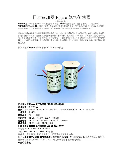
日本费加罗Figaro氧气传感器KE-25KE-50信息日本费加罗Figaro氧气传感器KE-25KE-50性能:测量范围:0-100%O2精度:氧气传感器KE-25:±1%(全量程);氧气传感器KE-50:±2%(全量程)工作温度:5~40℃储存温度:-20~+60℃响应时间:KE-25:14±2秒;KE-50:60±5秒初始输出:KE-25:10.0–15.5mv;KE-50:47.0-65.0mv期望寿命:KE-25:5年;KE-50:10年日本费加罗Figaro氧气传感器KE-25KE-50特性:长寿命(KE-25-5年,KE-50-10年)不受CO2,CO,H2S,NOx,H2影响低成本,在常温下工作信号输出定,无需外部电源不需加热以上日本费加罗Figaro氧气传感器技术参数以《OIML60号国际建议》92年版为基础,最新具体变化可查看《JJG669—12FIGARO广州南创传感器事业部检定规程》产品特性描述:氧气传感器KE-25KE-50属于半导体气体传感器不受CO2,CO,H2S,NOx,H2影响,氧气传感器KE-25KE-50低成本在常温下工作信号输出定,无需外部电源不需加热;精度氧气传。
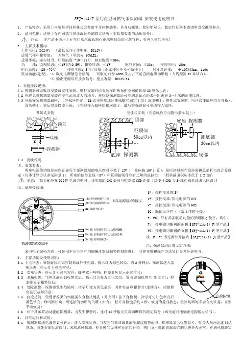
SFJ-11A/T 系列点型可燃气体探测器 安装使用说明书1、 产品特点:采用日本费加罗技研株式会社的半导体传感器,具有功耗低、使用年限长、稳定性好和不需调零或校准等特点。
2、 适用范围:适用于存在可燃气体泄漏危险的固定场所(有防爆要求的场所除外)。
注意: 本产品不适用于存在硅蒸汽或长期存在浓度较高的可燃气体、有害气体的环境!3、 主要技术指标:工作电压:DC24V ; (最低允许工作电压:DC12V ) 适用气种和报警值: 天然气(甲烷):10%LEL ;适用环境:室内使用,环境温度 -10~55℃,相对湿度<95%;功 耗:监视状态:<1W(约0.5W),报警状态:<1W ; 响应时间:≤30s ; 预热时间:180s贮存温度:-25~70℃ 使用年限:5年(仅限于正常使用环境和条件下) 尺寸及净重: Ф107X43mm ,110g 联动功能(选配):⑴ 联动关断紧急切断阀: 可联动口径50mm 及其以下的直流电磁切断阀(布线距离10米以内); ⑵ 输出无源常开接点信号:接点容量:DC24V/1A4、安装接线说明:4.1 探测器可以吸顶安装或壁挂安装,壁挂安装时应安装在距所保护空间的顶部30厘米以内;4.2 应避免将探测器安装在空气流动过大的地方,并应使探测器距可能的泄漏点的水平距离在3~4米的范围以内。
4.3 应先安装探测器底座,可将底座固定于86式预埋盒或用膨胀螺丝固定于墙上或顶棚上;壁挂式安装时,应注意使底座的方向指示箭头朝上。
然后将连接线正确、可靠地接入底座的相应端子,最后将探测器可靠地拧入底座。
吸顶式安装壁挂式安装(注意底座方向指示箭头朝上)4.4 接线说明: ⑴、布线要求:所布电源线的线径应保证在每个探测器端的电压绝对不低于12V (一般应按15V 计算),这应该根据布线距离和总消耗电流计算确定(具体计算方法参见附录1);所布的信号总线(S+)和联动接线等应有足够的抗拉性,一般其截面积应不低于1.2 mm 2。
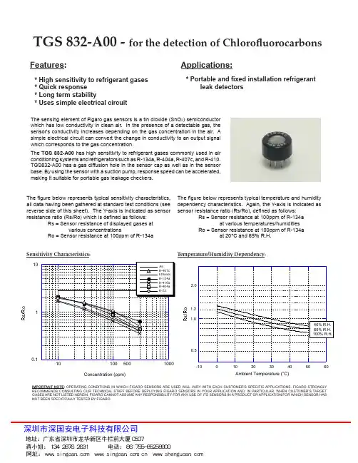
Applications:Features:TGS 832-A00 - for the detection of ChlorofluorocarbonsThe figure below represents typical sensitivity characteristics, all data having been gathered at standard test conditions (see reverse side of this sheet). The Y-axis is indicated as sensor resistance ratio (Rs/Ro) which is defined as follows: Rs = Sensor resistance of displayed gases at various concentrations Ro = Sensor resistance at 100ppm of R-134a The figure below represents typical temperature and humidity dependency characteristics. Again, the Y-axis is indicated as sensor resistance ratio (Rs/Ro), defined as follows: Rs = Sensor resistance at 100ppm of R-134a at various temperatures/humidities Ro = Sensor resistance at 100ppm of R-134a at 20°C and 65% R.H.The sensing element of Figaro gas sensors is a tin dioxide (SnO 2) semiconductor which has low conductivity in clean air. In the presence of a detectable gas, the sensor's conductivity increases depending on the gas concentration in the air. A simple electrical circuit can convert the change in conductivity to an output signal which corresponds to the gas concentration.The TGS 832-A00 has high sensitivity to refrigerant gases commonly used in air conditioning systems and refrigerators such as R-134a, R-404a, R-407c, and R-410.TGS832-A00 has a gas diffusion hole in the sensor cap as well as in the sensor base. By using the sensor with a suction pump, response speed can be accelerated, making it suitable for portable gas leakage checkers.* Portable and fixed installation refrigerant leak detectors* High sensitivity to refrigerant gases * Quick response * Long term stability* Uses simple electrical circuitTemperature/Humidity Dependency:Sensitivity Characteristics:1.21.0Structure and Dimensions:1 Sensing Element: SnO2 is sintered to form a thick film on the surface of an alumina ceramic tubewhich contains an internal heater.2 Sensor Cap 3 Sensor Base: Nylon 664 Flame Arrestor: 100 mesh SUS316 double gauzeStandard Circuit Conditions:Pin Connection and Basic Measuring Circuit:The numbers shown around the sensor symbol in the circuit diagram at the right correspond with the pin numbers shown in the sensor's structure drawing (above). When the sensor is connected as shown in the basic circuit, output across the Load Resistor (V RL ) increases as the sensor's resistance (Rs) decreases, depending on gas concentration.Sensor Resistance (Rs) is calculated by the following formula:Power dissipation across sensor electrodes (Ps) is calculated by the following formula:Standard Test Conditions:TGS 832 complies with the above electrical characteristics when the sensor is tested in standard conditions as specified below:Test Gas Conditions: 20°±2°C, 65±5%R.H.Circuit Conditions: V C = 10.0±0.1V (AC or DC), V H = 5.0±0.05V (AC or DC), R L = 10.0kΩ±1%Preheating period before testing: More than 7 days Electrical Characteristics:Basic Measuring Circuit:REV: 10/12Rs = ( -1) x R LV CV RLPs =V C 2 x Rs(Rs + R L )217 ± 0.59.516.5±0.56.5±0.51.0±0.563425145˚45˚um : mm。
TGS681x 气体传感器是采用独一无二的失效保护理念设计而成的非常独特的催化燃烧式传感器。
本手册提供了关于使用费加罗的独特催化型传感器TGS6810和TGS6812的气体检测器在设计和制造方面的重要技术建议。
目 录概要.....................................................................................................................................2电路设计 基本电路................................................................................................................2 传感器故障............................................................................................................3 加热过程中的报警预防......................................................................................3 报警延迟电路.......................................................................................................3印刷电路板和壳体设计 传感器的位置依赖性...........................................................................................3 快速响应之壳体设计 (4)制造工艺 传感器操作和保管...............................................................................................4 印刷电路板装配...................................................................................................4 传感器装配............................................................................................................4 预热...................................................................................................4 校正........................................................................................................................5 最终装配................................................................................................................6 气体调校................................................................................................................6 成品的保管 (6)采用TGS681x的可燃气体检测器应用手册重要提示:费加罗传感器的使用条件将因不同客户的具体运用不同而不同。

Technical Information for Carbon Monoxide SensorsF igaro’s TGS5042 is a battery operable electrochemical sensor which offers several advantages over traditional electrochemical sensors. Its electrolyte is environmentally friendly, it poses no risk of electrolyte leakage, can detect concentrations as high as 1% CO, operates in a range from -5˚ and +55˚C, and it has lower sensitivity to interference gases. With a long life, good long term stability, and high accuracy, this sensor is the ideal choice for CO detectors with digital display. OEM customers will find individual sensors data printed on each sensor in bar code from, enabling users to skip the costly gas calibration process and allowing for individual sensor tracking. TGS5042 utilizes a standard AA battery-sized package.S p e c i f i c a t i o n s P a g e Features..................................................................................................2 Applications...............................................................................................2 Structure...........................................................................................2 Basic Measuring Circuit...........................................................................2 Operating Conditions & Specifications...................................................3 Mechanical Strength..............................................................................3 Dimensions...................................................................................................3Operation Principle ......................................................................................................4Basic Sensitivity Characteristics Sensitivity to Various Gases............................................................5 Temperature and Humidity Dependency.............................................5 Gas Response Pattern.................................................................................6 Repeatability.............................................................................6 Influence of Storage...................................................................................6 Normal Operation Test.....................................................................................7 Sensitivity Test...................................................................................7Reliability Interference Gas Test......................................................................................8 Long-Term Stability................................................................................9 Corrosion Test...........................................................................................9 Variable Ambient Temperature Test................................................................9 Humidity Test.............................................................................................10 Stability Tests..................................................................................................11 Sequential Test...........................................................................................11 Dust Test................................................................................................12 Water Loss Test.......................................................................................12Marking ..........................................................................................................................12Cautions .......................................................................................................13Appendix . (14)a n I S O 9001 c o m p a n yIMPORTANT NOTE: OPERATING CONDITIONS IN WHICH FIGARO SENSORS ARE USED WILL VARY WITH EACH CUSTOMER’S SPECIFIC APPLICATIONS. FIGARO STRONGLY RECOMMENDS CONSULT-ING OUR TECHNICAL STAFF BEFORE DEPLOYING FIGARO SENSORS IN YOUR APPLICATION AND, IN PARTICULAR, WHEN CUSTOMER’S TARGET GASES ARE NOT LISTED HEREIN. FIGARO CANNOT ASSUME ANY RESPONSIBILITY FOR ANY USE OF ITS SENSORS IN A PRODUCT OR APPLICATION FORWHICH SENSOR HAS NOT BEEN SPECIFICALLY TESTED BY FIGARO.TGS5042 is a UL recognized component in accordance with the requirements of UL2034. Please note that component recognition testing has confirmed long term stability in 15ppm of carbon monoxide; other characteristics shown in this brochure have not been confirmed by UL as part of component recognition.1. Specifications1-1 Features* Battery operable* High repeatability/selectivity to carbon monoxide * Linear relationship between CO gas concentration and sensor output* Simple calibration* Long life* UL recognized component* Meets UL2034, EN50291, and RoHS requirements 1-2 Applications* Residential and commercial CO detectors* CO monitors for industrial applications* Ventilation control for indoor parking garages* Fire detection1-3 StructureFigure 1 shows the structure of TGS5042. The gas sensing layer is sandwiched between a stainless steel washer (counter electrode) and a stainless steel cap (working electrode), together with gas diffusion control stainless film and backing layers. This assembly is placed in the compartment of the stainless steel can. Water is stored in the bottom compartment and a charcoal filter is installed inside the stainless steel cap.1-4 Basic measuring circuitF igure 2 shows the basic measuring circuit of TGS5042. The sensor generates a minute electric current which is converted into sensor output voltage (Vout) by an op-amp/ resistor (R1) combination.Figaro recommends the following electrical parts:R1 : 1MΩC1 : 1µFIC : AD708An additional resistor or F ET is required to prevent polarization of the sensor when circuit voltage is off. NOTE: When voltage is applied to the sensor output terminal, the sensor may be damaged. Voltage applied to the sensor should be strictly limited to less than ±10mV.1-5 Operating conditions & specifications (Table 1)Figure 1 - Sensor structureFigure 2 - Basic measuring circuit(Including equivalent circuit)Cap /Working electrodeVoutNOTE 1: Sensor output in air under operating conditionsNOTE 2:If the water in the reservoir should freeze very rapidly (typically occurs only under artifically created conditions), irreversible change to sensor characteristics would occur. To avoid this risk, the sensor is recommended to be positioned with its cap (working electrode) facing up. NOTE 3: Please contact Figaro for more information if the required temperature range would exceed the specified limits.Table 1 - Operating conditions and specifications1-6 Mechanical strengthThe sensor shall have no abnormal findings in its structure and shall satisfy the above electrical specifications after the following performance tests: Withstand force -withstand force of 10kg (cap from metal can) along a vertical axisVibration - frequency--10~500Hz (equiv. to 10G), duration - 6 hours, x-y-z directionShock - acceleration-100G, repeat 5 times 1-7 Dimensions (see Fig. 3)Figure 3 - DimensionsAll sensor characteristics shown in this brochu re represent typical characteristics. Actu al characteristics vary from sensor to sensor and from production lot to production lot. The only characteristics warranted are those shown in the Specification.NOTE: The sensor can be supplied with lead pins. Please refer to the Appendix for detailsTop viewBottom viewSide view2. Operation PrincipleThe electrolyte of TGS5042 is a very low concentra-tion of mixed/prepared alkaline electrolyteconsisting of KOH, KHCO 3, and K 2CO 3. Themixed alkaline electrolyte acts as a buffer solution with a pH value maintained between 7~10. When CO passes through the backing layer and reaches to the working electrode, electrons are generated resulting from the reaction between CO and anionsin the electrolyte such as OH -, HCO 3-, and CO 32-(see equations 1a~1c ). By creating a short circuitbetween the working and counter electrodes with external wiring, electrons move to the counter electrode through the external wiring. At that point, the consumed anions in the electrolyte at the working electrode are replenished and move to the electrolyte by the reaction of CO 2, water, and electrons as shown in equations 2a~2c. The total reaction is expressed as shown in equation 3.A linear relationship exists between the sensor'selectric current and CO concentration (see equation 4). By calibrating the sensor with a known concentration of CO gas, the output current of the sensor can then be used to quantitatively determine CO concentration.Since, unlike conventional dry batteries, there is no consumption of active materials or of the electrodes, TGS5042 possesses excellent long-term stability for its output signal and enables maintenance-free operation. Furthermore, the sensor's self-generating output current makes it ideal for usage in battery-operated CO detectors.Figure 4 - Operation principleFigure 5 - Schematic diagram of TGS5042operating principleSeparator immersed in liquid alkaline electrolyteWorking electrode (Anodic reaction)CO + 2OH - → CO 2 + H 2O + 2e - (equation 1a )CO + 2HCO 3- → 3CO 2 + H 2O + 2e - (equation 1b )CO + CO 32- → 2CO 2 + 2e - (equation 1c )Counter electrode (Cathodic reaction)1/2O 2 + H 2O + 2e - → 2OH - (equation 2a ) 1/2O 2 + 2CO 2 + H 2O + 2e - → 2HCO 3- (equation 2b ) 1/2O 2 + CO 2 + 2e - → CO 32- (equation 2c )Total reactionCO + 1/2 O 2 → CO 2 (equation 3)Theoretical output current valueI = F x (A/σ) x D x C x n (equation 4) where :F : Faraday constant A: Surface area of diffusion filmD: Gas diffusion co-efficient C: Gas concentration σ: Thickness of diffusion filmn: Number of reaction electrons深圳市深国安电子科技有限公司3. Basic Sensitivity Characteristics 3-1 Sensitivity to various gasesF igure 6 shows the sensor’s sensitivity to various gases. The Y-axis shows output current (Iout/µA) in each gas. The output current is linear to CO concen-tration, with a deviation of less than ±5% in the range of 0~500ppm. Cross sensitivity data for other gases than those in Figure 6 are tabulated in Table Y.3-2 Temperature and humidity dependencyF igure 7a shows the temperature dependency of TGS5042 under a constant humidity of 50%RH. The Y-axis shows the ratio of output current in 400ppm of CO at various temperatures (I) to the output current in 400ppm of CO at 20˚C/50%RH (Io). Temperature dependency is based on the difference in the catalytic reaction rate on the electrodes, and it can be simply compensated by utilizing a thermistor. This linear relationship between I/Io and CO concentration is constant regardless of CO concentration range, according to the sensor's operating principle.F igure 7b shows the humidity dependency of TGS5042 under constant temperatures of 20˚C and 50˚C. The Y-axis shows the ratio of output current in 400ppm of CO at various relative humidities (I) to the output current in 400ppm of CO at 20˚C/50%RH (Io). This data demonstrates that humidity dependency is negligible as temperature varies.Figure 6 - Sensitivity to various gasesFigure 7a - Temperature dependency at 400ppm CO/50%RH(Io=sensor output current at 20˚C)Figure 7b - Humidity dependency at 400ppm CO(Io=sensor output current at 50%RH)0.00.51.01.52.020406080100Relative Humidity (%)Note : The figures in this table are typical values and should not be used as a basis for cross calibration. Cross sensitivity for various gases may not be linear and should not be scaled. All data based on a 4 minute exposure. For some gases, filter saturation and gas breakthrough mayoccur if gas is applied for a longer time period.0.00.51.01.52.0-10102030405060Temperature (˚C)3-3 Gas response patternF igure 8 shows the gas response pattern of the output signal when the sensor is placed into 30, 70, 150 and 400ppm of CO and then returned to normal air. The response time to 90% of the saturated signal level is within 60 seconds, and the recovery of the signal back to 90% of the base level is within 120 seconds. This data demonstrates that TGS5042 possesses sufficient response speed for meeting UL requirements for CO detectors.3-4 RepeatabilityF igure 9 shows the pattern of the output signal when the sensor is repeatedly exposed to 400ppm of CO at a constant interval of 240 seconds. The data demonstrates extremely high reproducibility of the output signal, the deviation being less than ±5%.3-5 Influence of storageF igure 10 shows the initial action of the sensor's output current signal in fresh air. F or the purpose of this test, sensors were stored for more than six months under two separate conditions between the working and counter electrodes: in short-circuited condition, and in open-circuited condition. The chart illustrates the behavior of sensor output current for each group just after installation into the operating circuit. The output current signal of sensors stored in a short-circuited condition reaches its saturated level quickly, while those stored with an open-circuit exhibit much slower behavior. Since sensors are shipped in an open-circuit condition, stabilization time of one hour (typical) is recommended. If an anti-polarization circuit is used (see Item 2-5 in Application Notes for TGS5042), placing the sensor onto the pcb for one hour should be sufficient to stabilize the output. If no anti-polarization circuit is used, placing the sensor into the detector circuit and powering the circuit for about one hour should be sufficient to stabilize sensor output.Figure 8 - Response patternFigure 9 - Repeatability (in 400ppm of CO)0.00.20.40.60.81.00500100015002000Time (sec.)-0.20.00.20.40.60.81.00500100015002000Time (sec.)Figure 10 - Influence of storage(in fresh air)Figure 11a shows the result of the “Normal Operation Test” required by UL2034, Sec. 35.3 where the sensor is exposed to 600ppm of CO for 12 hours at 20˚C/40%RH. Stable output current signal can be seen throughout the exposure.In addition, F igure 11b shows the CO sensitivity characteristics of the sensor before, during, and after the Normal Operation Test, demonstrating that TGS5042 is hardly influenced by exposure to high concentrations of CO.3-7 Sensitivity testFigure 12a shows the results of the “Sensitivity Test” as required by UL2034, Sec. 38. Under this test, the sensor was exposed to 30, 70, 150 and 400ppm of CO at 20˚C/40%RH. The period of exposure was varied by concentration, corresponding with the maximum time in which a CO detector should generate an alarm for the subject concentration. Throughout the test exposures, TGS5042 displayed a reasonable and stable output current signal.Figure 11a - Normal operation test (CO 600±30ppm for 12 hours at 20˚C/40%RH) 0.00.51.01.5Figure 11b - Normal operation test(20˚C/40%RH)0.20.40.60.81Figure 12a - Sensitivity test(20˚C/40%RH)In addition, Figure 12b indicates the CO sensitivity characteristics of the sensor before, during, and after the Sensitivity Test, demonstrating the excellent reproducibility of TGS5042's CO sensitiv-ity characteristics.4. ReliabilityT ests conducted in this section demonstrate that TGS5042 can meet the requirements of various testing standards without incurring adverse long term effects from such tests.4-1 Interference gas testFigure 13a shows the results of testing the TGS5042 sensor for durability against various interference gases as specified by UL2034, Sec. 39. The test was conducted by exposing the sensor to each gas shown in Figure 13a (starting with CO 30ppm) for two hours, then removing the sensor to fresh air for just one hour, and followed by inserting the sensor into the next gas. This procedure was repeated for the full range of gases shown in Figure 13a. Because the sensor is exposed to each of the test gases consecutively, to some small extent the effect of the previous test gas may affect subsequent tests for a short period. However, despite the short-term effects of such gases remaining after exposure, the sensor still shows significantly less sensitivity to each test gas when compared to 30ppm of CO, and CO sensitivity remains unaffected.In addition, F igure 13b shows the CO sensitivity characteristics of the sensor before and after this test, further demonstrating the excellent reproducibility of the CO sensitivity characteristics of TGS5042, demonstrating its durability against the interference gases listed in the requirements of UL2034, Sec. 39.Fig. 12b - Sensitivity test(20˚C/40%RH)Figure 13a - Interference gas test(20˚C/40%RH)-0.020.020.040.060.08AC O30p pM et h an e500ppB ut a ne300p pH ep t an e500ppE th yl ac et a te200p pI P A200ppC O25000ppN H3100p pE th an ol200p pT ol u en e200ppT ri c hl o ro et h an e200ppA ce t on e200ppC O30p p AFigure 13b - Interference gas test(20˚C/40%RH)深圳市深国安电子科技有限公司4-2 Long-term stabilityigure 14 shows long-term stability data for TGS5042. Test samples were stored in natural clean air under a short-circuit condition and measured at various intervals as dictated by the standard test conditions of UL2034, Sec. 38. The Y-axis shows the ratio of output current in 300ppm of CO at any point in time (I) over output current in 300ppm of CO on the first day of the test (Io). This chart demonstrates very stable characteristics with a variation of less than ±15% for more than 7 years.4-3 Corrosion testTo demonstrate the durability of TGS5042 against corrosion, samples were subjected to test conditions called for by UL2034, Sec.58-Corrosion Test. Over a three-week period, a mixture of 100ppb of H2S, 20ppb of Cl2, and 200ppb of NO2 was supplied to the sensors at a rate sufficient to achieve an air exchange rate of five times per hour. Figure 15 shows the CO sensitivity characteristics before and after exposure in the above conditions, demonstrating that TGS5042 is hardly influenced by such corrosive gases. In addition, the sensor's stainless steel housing did not show any sign of corrosion as a result of this test.4-4 Variable ambient temperature testTo demonstrate the ability of TGS5042 to withstand the effects of high and low temperature, the “Variable Ambient Temperature Test” of UL2034, Sec. 45 was conducted.(1) Operation in high and low temperature test Figure 16a shows the results for the “Operation in High and Low Temperature Test” of UL2034, Sec.45.1. The sensor was exposed to environments of 0˚C/15%RH and 49˚C/40%RH for at least three hours each, with measurements taken before and during the exposure in accordance with the test conditions of UL2034, Sec. 38. By plotting the output current values from these test measurements atop the data taken prior to this test at a constant 50%RH (representing standard temperature dependency), it can be seen that the test data are still in line with data taken at a constant RH. The conclusion which can be drawn is that, regardless of exposure to extremes of temperature and humidity, the sensor's output is not affected by humidity. As a result, TGS5042 can meet the requirements of UL2034, Sec. 45.1 by utilizing a simple temperature compensation method.Figure 14 - Long term stabilityFigure 15 - Durability against corrosionFigure 16a - Operation in high and low temperature (all data at 50%RH except Sec. 45.1 test points) 0.00.51.01.52.02.53.0Time (days)(2) Effect of shipping and storageTo verify the effects of shipping and storage, the sensor was tested under the conditions of UL2034, Sec. 45.2. Test samples in a short-circuited condition were subjected to 70˚C for 24 hours, allowed to cool to room temperature for 1 hour, subjected to -40˚C for 3 hours, and then allowed to warm up to room temperature for 3 hours. Figure 16b shows the CO sensitivity characteristics before and after the test, demonstrating that TGS5042 meets the requirement of UL2034, Sec. 45.2.4-5 Humidity testF igure 17a shows the results of testing the sensor under UL2034, Sec. 46A. The sensor was exposed in an atmosphere of 52±3˚C/95±4%RH for a period of 168 hours, returned to normal air for 2 days, then followed by 168 hours exposure at 22±3˚C/10±3%RH. The data demonstrates the stable characteristics in both low and high humidity conditions.Figure 17b shows data taken prior to the above test at a constant relative humidity of 50%. These curves represent the typical temperature dependency of the sensor. When plotting measurements taken at the environmental extremes specified on UL2034, Sec. 46A (52±3˚C/95±4%RH and 22±3˚C/10±3%RH) onto the temperature dependency curves, it can be seen that measurements taken at these extreme conditions still fall in line with the temperature dependency curve derived prior to testing. The conclusion which can be drawn is that, regardless of exposure to extremes of temperature and humidity, the sensor's output is not affected by humidity. As a result, TGS5042 can meet the requirements of UL2034, Sec. 46A by utilizing a simple temperature compensation method.Figure 16b - Effects of shipping and storageFigure 17a - Humidity testFigure 17b - Humidity test(all data at 50%RH except Sec. 46A test points))4-6 Stability test(1) False alarm testTo show the sensor’s behavior under continuous low level exposure to CO, samples were tested against the procedure detailed in UL2034, Sec.41.1(c)-Stability Test. Test samples were exposed to 30ppm of CO continuously for a period of 30 days under standard circuit conditions. Figure 18 shows the CO sensitivity characteristics before and after the exposure test, demonstrating that detectors using TGS5042 will not give a false alarm as a result of continuous low level CO exposure.(2) Temperature cycle testIn accordance with UL2034, Sec. 41.1(e)-Stability Test, test samples were exposed to ten cycles (<1 hour and >15 minutes) of temperature from 0˚C/100%RH to 49˚C/40%RH. F igure 19 shows CO sensitivity characteristics before and after the cycle test, demonstrating that TGS5042 is hardly influenced by the extreme conditions of the temperature cycle test.4-7 Sequential testIn UL2034, Sec. 41.3, a single lot of sample detectors are to be subjected to the following sequence of tests: Section 38, Section 41.1, Section 39, Section 45, and Section 46A. While TGS5042 meets the requirements of each of these test individually (as shown elsewhere in this brochure), this test is designed to demonstrate the sensor's ability to withstand all of these test when conducted in sequence. Figure 20 shows the results of sequentially testing the same lot of sensors. The good stability of the sensor's output signal indicates that TGS5042 can satisfy the requirements of UL2034, Sec. 41.3-Sequential Test.Figure 18 - False alarm testFigure 19 - Temperature cycle testB ef o re te st i ngA ft e rS ec.38t e stA ft e rS ec.41.1t e stA ft e rS ec.39t e stB ef o re Se c.45.1v ar.am bi e nt t em pt e stA ft e rS ec.45.1v ar.am bi e nt t em pt e st(0˚C)A ft e rS ec.45.1v ar.am bi e nt t em pt e st(49˚C)B ef o re Se c.45.2s hi p pi n g/s to r ag et e stA ft e rS ec.45.2s hi p pi n g/s to r ag et e st(-40˚C)A ft e rS ec.45.2s hi p pi n g/s to r ag et e st(70˚C)B ef o re Se c.46Ah i gh hu mi d it yt e st t es tA ft e rS ec.46A hi g hh um id i ty te st t es tA ft e rS ec.46A lo wh um id i ty te st t es tA ft e rs eq ue nt i al t es tA ft e rS ec.35.3t e stFigure 20 - Sequential test4-8 Dust testTo judge the effect of dust contamination on TGS5042, approximately 2 ounces (0.06 kg) of cement dust, capable of passing through a 200 mesh screen, was circulated for 1 hour by means of a blower, enveloping the sensor in the test chamber. Air flow was maintained at an air velocity of approximately 50 fpm (0.25 m/s) at 20˚C/40%RH. Figure 21 shows the sensor's CO sensitivity characteristics before and after the dust exposure test. This data demonstrates that the dust test of UL2034, Sec. 53 has a negligible effect on CO sensitivity.4-9 Water loss testF or evaluating the life expectancy of TGS5042 from the viewpoint of its water reservoir (which prevents the electrolyte from drying up), the weight loss of TGS5042 was periodically measured when stored at 20˚C/40%RH and 70˚C/5%RH respectively. F igure 22 demonstrates that the sensor’s weight decreased linearly with time due to evaporation of the water. The rate of water loss under various temperature was related with the water vapor pressure at each temperature. According to calculations based on this rate of water loss and the differences in water vapor pressure in 20˚C and 70˚C, the water (>4.5g initially) will last more than 10 years under natural residential conditions such as 20˚C/40%RH.5. MarkingThe TGS5042 comes with a sticker attached to the sensor housing which contains important information. The one dimensional bar code indicates the sensor's sensitivity (slope) in numeric value as determined by measuring the sensor's output in 300ppm of CO:xxxx = x.xxx nA/ppmIn user readable format, the sensor's sensitivity per ppm (nA) is printed below the one dimensional bar code and the sensor's Lot Number is printed to the left of the sensitivity data. Please note that three decimal places should be added to the sensitivity reading (e.g. 1827 should be read as 1.827 nA/ppm).-0.10-0.08-0.06-0.04-0.020.00020*********Time (days)Figure 22 - Water loss testFigure 21 - Dust test1827Sensitivity to CO (nA/ppm)FIGAROTGS5042(Ex.1827 = 1.827nA/ ppm)Figure 23 - TGS5042 markings(NOTE:UL Mark may appear on shrink tube)6. Cautions6-1 Situations which must be avoided1) Disassembling the sensorUnder no circumstances should the sensor be disassem-bled, nor should the sensor can and/or cap be deformed.2) Contamination by alkaline metalsSensor characteristics may be significantly changed when the sensor is contaminated by alkaline metals, especially salt water spray.3) Exposure to high concentration of basic (non-acidic) gases Sensor characteristics may be irreversibly changed by the exposure to high concentrations of basic gases such as ammonia.4) High temperature exposureAt temperatures of 80˚C or higher, the sensing membrane may deteriorate, resulting in irreversible change of sensor characteristics.5) Contact with waterSensor characteristics may be changed due to soaking or splashing the sensor with water.6) Application of excessive voltageIf higher than specified voltage is applied to the sensor, breakage may occur or sensor characteristics may drift, even if no physical damage or breakage occurs. Do not use the sensor once excessive voltage is applied.6-2 Situations to avoid whenever possible1) Exposure to silicone vaporsAvoid exposure of sensor where silicone adhesives, hair grooming materials, or silicone rubber/putty may be present. Silicone vapors may cause clogging of the gas diffusion route.2) Dew condensationIf severe dew condensation occurs for a long period inside of the sensor or on the sensor surface, it may cause clogging of gas diffusion route or deterioration of the sensing membrane. Mild dew condensation which occurs in normal indoor air would not cause any significant damage.3) Storage in sealed containerDo not keep the sensor in a sealed containers such as sealed bag. Due to ambient temperature change, dew condensation may occur inside the sensor if the sensor is stored in this manner.4) FreezingWhen subjected to temperatures below 0˚C, it is possible that the water in the reservoir may freeze. Since water volume will expand when freezing, the sensor can may undergo some deformation. Care should be taken in the design of the detector to ensure that the sensor is not placed too close to other components or the circuit pattern on a PCB, as such deformation may cause the sensor to come in contact with these items. In addition, if the freezing process were to occur very rapidly, the sensor will undergo irreversible change in its characteristics. To avoid this risk, it is recommended that the sensor be positioned with the cap (working electrode) facing up (for more information, refer to Item 3-1 Position Dependency of the Sensor in the document Application Notes for TGS5042).5) Exposure to hydrogen sulfide or sulfuric acid gasIf the sensor is exposed to hydrogen sulfide or sulfuric acid gas, sensor components such as the gas diffusion film, can, and cap may be corroded, resulting in the sensor damage.6) Vibration and shockVibration and shock may cause an open or short circuit inside the sensor.7) Dust and oil mistExtremely high concentrations of dust or oil mist may cause clogging of the sensor's internal structure. When such conditions are expected to be encountered, installation of an external air filter is recommended.8) Flux for solderingManual soldering is recommended since high concen-trations of flux may affect sensor characteristics when the sensor is soldered by wave soldering. When wave soldering is used, a test should be conducted before production starts to see if there would be any influence to sensor characteristics. Please refer to Item 5-3 of Application Notes for TGS5042 for advice on manual soldering conditions. 9) Exposure to organic vaporsIf the sensor is exposed to organic vapors such as alcohols, acetone, or volatile oils, these gases may adsorb on the sensor surface, resulting in temporary sensor drift.6-3 Additional cautions for installationThis sensor requires the existence of oxygen in the operating environment to function properly and to exhibit the characteristics described in this brochure. The sensor will not operate properly in a zero oxygen environment. Figaro USA Inc. and the manufacturer, Figaro Engineering Inc. (together referred to as Figaro) reserve the right to makechanges without notice to any products herein to improve reliability, functioning or design. Information contained in this document is believed to be reliable. However, Figaro does not assume any liability arising out of the application or use of any product or circuit described herein; neither does it convey any license under its patent rights, nor the rights of others.F igaro's products are not authorized for use as critical components in life support applications wherein a failure or malfunction of the products may result in injury or threat to life.。
重要提示: 费加罗传感器的使用条件将因不同客户的具体运用不同而不同。
费加罗强烈建议在使用前咨询我们的技术人员,尤其是当客户的检测对象气体不在列表范围时,对于未经费加罗专业测试的任何使用,费加罗不承担任何责任。
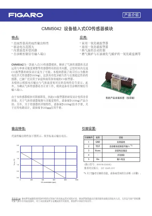
CMM5042 设备植入式CO传感器模块* 直线性很高的线性输出特性* 驱动电压范围大* 内置温度补偿回路* 自诊断控制信号输入端口特点:应用:* 家用一氧化碳报警器* 商用一氧化碳报警器* 换气扇的自动控制* 燃气锅炉与石油液化气暖炉的一氧化碳监测等CMM5042为一款嵌入式CO 传感器模块,解决了气体传感器的灵活运用与单体灵敏度调整等传感器特有的技术问题,让短时间内完成CO 报警器的研发设计成为了可能。
本模块搭载了我司引以为傲的电化学式传感器TGS5042,这款具有优异耐久性与长期稳定性的传感器,已被广泛应用于家庭和商用各领域的CO 报警器。
本模块以模拟电压输出与气体浓度相对应的直线性信号显示。
此外,为确认气体传感器是否正常工作,模块还备有自诊断控制信号输入端口。
由于本传感器模块可即插即用,因此CO 报警器的研发设计变得非常容易。
关于气体传感器规格与灵敏度特性,请参阅TGS5042产品介绍。
另外,关于传感器的详细特性,请参阅TGS5042技术手册,关于应用电路设计,请参阅 TGS5xxx 应用手册。
代表性输出特性如下图所示。
纵坐标表示输出电压。
(插口型号:BH05B-XMSK)推荐对应插头: JST: XMP-05V*1 关于TEST 引脚的功能,请参阅背面的自诊断(步骤)。
输出特性:引脚设置:0.00.51.01.52.02.52004006008001000CO concentration (ppm)V C O N C (V)有的产品未贴标签(仅印刷)REV.11/22在此产品规格书中所显示的都是传感器的典型特性,实际的传感器特性因产品不同而不同,详情请参阅各传感器唯一对应的规格表。
精品推介I Product Express的省空间化做出贡献。
使用3线式,通过IO-Link主站连接支持IO-Link的传感器和控制器,可实时发现异常位置和现象,缩短恢复时间。
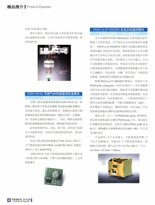
可燃气体传感器预校准模块FSM-10Y-01是一种搭载了费加罗半导体式传感器TGS2610-D00的模块,具有耐久性好、稳定性高的特点。
此模块可提供与被检测浓度成比例的PWM输岀(模块中带有一存储器,岀厂前预标定数据存储其中),同时,模块还能够检测到传感器断线及短路故障。
模块操作温度范围广。
此外如检测甲烷、丙烷、氢气等,对有机气体的交叉灵敏度很低,对硅化合物的耐受性更佳,更适应恶劣环境。
丙烷气体预校准检测模块FSM-10Y-01的特点:与气体浓度成比例的PWM、USART数字输出;免维护;体积小;符合RoHS要求。
FSM-10Y-01丙烷气体预校准检测模块主要应用于检测可燃气体泄漏、可燃气体泄漏检测仪、工业用探测器等。
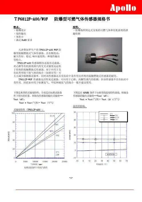
安全可编程控制器PNOZmulti2的使用通过软件配置十分简单易用。
用户现在还可以依靠新的扩展模块——PNOZ m EF8DI2DOT双极半导体输出模块来实现对机械压力机的安全监控。
模块提供两个安全双极输出用于控制压力机安全阀,或其他需要双极半导体信号切换的执行机构。
另外提供八个安全输入,它们 可以配置独立的滤波时间,所有相关的安全功能都可以被连接到该模块中,以便能够使用各种输入信号进行正确操作,比如急停、光栅、双手启动、凸轮监控传感器、断轴监控传感器和安全阀输出等。
配置PNOZ m EF8DI2DOT模块后,在软件工具PNOZmulti configurator(V10.7.0或以上)中可直接调用经过认证的压机功能块,例如用于压机操作模式或凸轮监控功能等,且全面的诊断选项帮助排故,从而 减少停机时间,非常简便经济。
一个特别的优势在于程序中会给该模块配置一个独立的模块程序(mIQ),其在模块上本地运行,循环时间短,仅为3ms,可以更快地控制输出切断从而获得更高的安全性。
费加罗传感器广州南创陈工FIGARO是一家专业生产半导体气体传感器的公司,1962年发明全球第一款半导体产品,目前全球第一。
FIGARO的产品远销38个国家,在多个国家设立了分支机构或办事处,生产基地遍布美洲、东欧、中国等地;并在中国设立了广州南创传感器事业部,可为用户的实验和生产提供最佳的服务与解决方案。
半导体气体传感器采用金属氧化物半导体烧结工艺,对被检测的检测气体具有灵敏度高、响应时间短、成本低、长期稳定性好等优点。
我们的产品包括可燃气体、有毒气体、空气质量、一氧化碳、二氧化碳、氨气、汽车尾气、酒精等传感器元件、传感模块等,以及各种气体传感器的配套产品。
目前已经被广泛应用于家用燃气报警器、工业有毒气体报警器、空气清新机、换气空调、空气质量控制、汽车尾气检测、蔬菜大棚、酒精检测、孵化机械等。
费加罗传感器KE-25KE-50信息费加罗传感器KE-25KE-50性能:测量范围:0-100%O2精度:氧气传感器KE-25:±1%(全量程);氧气传感器KE-50:±2%(全量程)工作温度:5~40℃储存温度:-20~+60℃响应时间:KE-25:14±2秒;KE-50:60±5秒初始输出:KE-25:10.0–15.5mv;KE-50:47.0-65.0mv期望寿命:KE-25:5年;KE-50:10年费加罗传感器KE-25KE-50特性:长寿命(KE-25-5年,KE-50-10年)不受CO2,CO,H2S,NOx,H2影响低成本,在常温下工作信号输出定,无需外部电源不需加热以上费加罗传感器技术参数以《OIML60号国际建议》92年版为基础,最新具体变化可查看《JJG669—12FIGARO广州南创传感器事业部检定规程》产品特性描述:氧气传感器KE-25KE-50属于半导体气体传感器不受CO2,CO,H2S,NOx,H2影响,氧气传感器KE-25KE-50低成本在常温下工作信号输出定,无需外部电源不需加热;精度氧气传。
日本费加罗催化燃烧可燃气体传感器TGS6812 Technical Information for Hydrogen Gas SensorsThe Figaro TGS6812 catalytic type gas sensor can detect levels of hydrogen up to 100%LEL. This sensor features high accuracy, good d urability and stability, quick response, and linear output. This sensor can detect hydrogen as well as methane and LP gas, making it an excellent solution for monitoring gas leakage from stationary fuel cell systems which transform combustible gases into hydrogen.P a g e Basic Information and SpecificationsFeatures (2)Applications (2)Structure..........................................................................2 Basic Measuring Circuit....................................................2 Circuit & Operating Conditions.. (3)Specifications (3)Dimensions...............................................................................3Typical Sensitivity Characteristics Sensitivity to Various Gases................................................4 Temperature Dependency...........................................................4 Humidity Dependency...........................................................4 Heater Voltage Dependency.............................................5 Gas Response....................................................................................5 Initial Action........................................................................5Reliability Long Term Characteristics.............................................................6 Durability to Hydrogen.......................................................................6 Durability to Sulphur Dioxide...........................................................6 Durability toNitrogen Dioxide.........................................................7 Durability to HMDS....................................................................7 Effects of Air Flow.............................................................................7Cautions (8)a n I S O 9001 c o m p a n yIMPORTANT NOTE: OPERATING CONDITIONS IN WHICH FIGARO SENSORS ARE USED WILL VARY WITH EACH CUSTOMER’S SPECIFIC APPLICATIONS. FIGARO STRONGLY RECOMMENDS CONSULTING OUR TECHNICAL STAFF BEFORE DEPLOYING FIGARO SENSORS IN YOUR APPLICATION AND, IN PARTICULAR, WH EN CUSTOMER’S TARGET GASES ARE NOT LISTED H EREIN. FIGARO CANNOT ASSUME ANY RESPONSIBILITY FOR ANY USE OF ITS SENSORS IN A PRODUCT OR APPLICATION FOR WHICH A SENSOR HAS NOT BEEN SPECIFICALLY TESTED BY FIGARO.1. Basic Information and Specifications 1-1 Features* Linear output * Compact size* Small sensitivity to alcohol* Sensitive to hydrogen, methane, and LP gas * Meets RoHS requirements 1-2 Applications* Hydrogen and combustible gas leak detectors for fuel cell applications1-3 StructureFigure 1 shows the structure of TGS6812. The sensor is comprised of two elements: element (D) which is sensitive to combustible gases, and a reference element (C) which does not have sensitivity to combustible gases. The sensing element (D) is made of alumina doped with catalysts, while the reference element (C) is made of alumina. Both coils are made of Pt wire,and the wires of both elements (D) and (C) are connected to nickel pins No. 2 & 3 and No. 1 & 4 respectively. The sensor base and cap are made of reinforced Polybutylene Terephthalate (PBT). The upper opening in the cap is covered with a double layer of 100 mesh stainless steel gauze (SUS316). The TGS6812 utilizes a zeolite filter inside the cap for reducing the influence of interference gases.1-4 Basic measuring circuitThe T GS6812 i s c omprised o f t wo e lements: 1) e lement (D) which is sensitive to combustible gases and 2) a reference element (C) which is not sensitive to combustible gases. These elements are installed into a “Wheatstone Bridge”. A variable resistor should be adjusted so that the bridge will produce a stable baseline signal when in an environment free of combustible gases. When combustible gases are present, they will be combusted on the detecting element, causing its temperature to rise. Accordingly the resistance of this element will increase. This results in an “out-of-balance” signal across the bridge and a corresponding change in output voltage which can be measured.Fig. 1 - Sensor structureFig. 2 - Basic measuring circuitTop viewSide viewu/m = mmCapBottom viewBaseDetector sideCompensator side1-4 : Compensator 2-3 : Detector1-5 Circuit & operating conditionsThe ratings shown below should be maintained at all times to insure stable sensor performance:1-6 Specifications NOTE 1Mechanical Strength:The sensor shall have no abnormal findings in its structure and shall satisfy the above electricalspecifications after the following performance tests: Vibration - Drop test -frequency:10~150H z, accel-eration: 2G, duration:10 times, direction: three dimensions drop onto a cement floor from a height of 250mm, repeated 5 times NOTE 1:Sensitivity characteristics are obtained under the following standard test conditions:(Standard test conditions)Temperature a nd humidity: 20 ± 2?C, 65 ± 5% RH Circuit conditions:V H = 3.0±0.05V AC/DC Preheating period: 30 seconds or more under standard circuit conditions 1-7 Dimensions Fig. 3 - Sensor dimensionsAll sensor characteristics shown in this brochurerepresent typical characteristics. Actualcharacteristics vary from sensor to sensor andfrom production lot to production lot. The only characteristics warranted are those shown inthe Specification table above.-101020304050020*********Relative humidity (%RH)2-2 Temperature dependencyFigure 5 shows the temperature dependency of TGS6812 at 65%RH in 10%LEL of methane, LP gas, and hydrogen. Since the temperature dependency of element (D) is compensated by element (C), the temperature dependency of sensor output in the range from -10?C to +70?C is very small.2-3 Humidity dependencyFigure 6 shows the relative humidity dependencyof TGS6812 under constant temperature of 20?C in 10%LEL of methane, LP gas, and hydrogen. This data demonstrates that the humidity dependency of TGS6812 is negligible as humidity varies.Fig. 4 - TGS6812 sensitivity to various gasesFig. 6 - TGS6812 humidity dependency-10010203040502.902.953.003.05 3.10Operating voltage (V)2-4 Heater voltage dependencyFigure 7 shows the change in the sensor output according to variations in the heater voltage (V H ).Note that 3.0±0.1V as a heater voltage must be maintained because variance in applied heater voltage will cause the sensor’s characteristics to be changed from the typical characteristics shown in this brochure.2-5 Gas responseFigure 8 shows the change pattern of sensor output (Vout) for TGS6812 when the sensor is inserted 4000ppm of hydrogen.As these charts display, the sensor’s response speed to the presence of gas is extremely quick.2-6 Initial actionnormal air and later energized in clean air.warm-up process is called “Initial Action”.powering on, it is recommended that an initial delay circuit be incorporated into the detector’s design. This is esp ecially recommended for intermittent-operating devices such as portable gas detectors.Fig. 7 - Heater voltage dependencyFig. 8 - Gas responseFig. 9- Initial action-1010201020-101020period.3-2 Durability to hydrogenconcentration exposure to hydrogen gas. The measurement was taken, the sensor was exposed to 1% of H 2 for over 2000 hours. At each measurement point, the sensor was removed from H 2measuring sensor output.characteristics after exposure to high concentrations of hydrogen.3-3 Durability to sulphur dioxideFigure 12 shows the effect on TGS6812 of exposure to SO 2. The initial point of the graph shows the value of sensor output prior to SO 2 exposure. After the initial measurement was taken, the sensor was exposed to 25ppm of SO 2 for over 2400 hours in total. At each measurement point, the sensor was removed from SO 2 and energized in normal air for 10 hours prior to measuring the sensor output.The data demonstrates that TGS6812 shows stable characteristics after exposure to SO 2.Fig. 11 - Durability to hydrogenFig. 12 - Durability to SO 2-101020-101020characteristics after exposure to NO 2. 3-5 Durability to HMDSFigure 14 shows the effect on TGS6812 of exposure to HMDS.The initial point of the graph shows the value of sensor output prior to HMDS exposure. After the initial measurement was taken, the sensor was exposed to 10ppm of HMDS for one hour in total. At each measurement point, the sensor was removed from HMDS and energized in normal air for 1 hour prior to measuring the sensor output.This data demonstrates that TGS6812 shows stable characteristics after exposure to HMDS.3-6 Effects of Air FlowTable 1 shows how the sensor is affected by airflows (refer to Fig. 15 for illustration of airflows in Table 1). This data demonstrates that there is no significant influence on the sensor by an air flow of 3.1 meters/sec.Fig. 14 - Durability to HMDSFig. 15 - Air flow testing direction (ref. Table 1)Table 1 - Effects of air flow on output voltage4 Cautions on Usage of Figaro Gas Sensors4-1 Situations which must be avoided1) Exposure to silicone vaporsIf silicone vapors adsorb onto the sensor’s surface, the sensing material will be coated, irreversibly inhibiting sensitivity. Avoid exposure where silicone adhesives, hair grooming materials, or silicone rubber/putty may be present.2) Highly corrosive environmentHigh density exposure to corrosive materials such as H2S, SOx, Cl2, HCl, etc. for extended periods may cause corrosion or breakage of the lead wires or heater material.3) Contamination by alkaline metalsSensor drift may occur when the sensor is contaminated by alkaline metals, especially salt water spray.4) Contact with waterSensor drift may occur due to soaking or splashing the sensor with water.5) FreezingIf water freezes on the sensing surface, the sensing material would crack, altering characteristics.6) Application of excessive voltageIf higher than specified voltage is applied to the sensor, the lead wires and/or sensor elements may be damaged or sensor characteristics may drift, even if no physical damage or breakage occurs.7) Operation in zero/low oxygen environment TGS6812 requires the presence of a certain amount of oxygen in its operating environment in order to generate a combustion reaction of gas on the sensor’s surface. It cannot properly operate in a zero or low oxygen content atmosphere.8) Excessive exposure to alcoholIf TGS6812 is exposed to high concentrations of alcohol (such as 10,000ppm or more) for a long period, the filter may become saturated. In this case, the sensor would show a lower resistance in alcohol than indicated in Figure 4.9) VibrationExcessive vibration may result in zero drift or cause the sensor or lead wires to resonate and break. Usage of compressed air drivers/ultrasonic welders on assembly lines may generate such vibration, so tests should be conducted to verify that there will be no influence on sensor characteristics.10) ShockZero drift and breakage of lead wires may occur if the sensor is subjected to a strong shock. To avoid shock, please keep the sensor in the original packing foam during storage.4-2 Situations to be avoided whenever possible1) Water condensationLight condensation under conditions of indoor usage should not pose a problem for sensor performance.H owever, if water condenses on the sensor’s surface and remains for an extended period, sensor characteristics may drift.2) Usage in high density of gasSensor performance may be affected if exposed to a high density of gas for a long period of time, regardless of the powering condition.3) Storage for extended periodsWhen stored without powering for a long period, the sensor may show a reversible drift in resistance according to the environment in which it was stored. The sensor should be stored in a sealed bag containing clean air; do not use silica gel. Note that as unpowered storage becomes longer, a longer preheating period is required to stabilize the sensor before usage. 4) Long term exposure in adverse environment Regardless of powering condition, if the sensor is exposed in extreme conditions such as very high humidity, extreme temperatures, or high contamination levels for a long period of time, sensor performance will be adversely affected.5) SolderingIdeally, sensors should be soldered manually.H owever, wave soldering can be done under the following conditions:a) Suggested flux: rosin flux with minimal chlorineb) Speed: 1-2 meters/min.c) Preheating temperature: 100±20?Cd) Solder temperature: 250±10?Ce) Up to two passes through wave soldering machine allowed Results of wave soldering cannot be guaranteed if conducted outside the above guidelines since someFigaro USA Inc. and the manufacturer, Figaro Engineering Inc. (together referred to as Figaro) reserve the right to make changes without notice to any products herein to improve reliability , functioning or design. Information contained in this document is believed to be reliable. H owever, Figaro does not assume any liability arising out of the application or use of any product or circuit described herein; neither does it convey any license under its patent rights, nor the rights of others.Figaro’s products are not authorized for use as critical components in life support applications wherein a failure or malfunction of the products may result in injury or threat to life.flux vapors may cause drift in sensor performance similar to the effects of silicone vapors.。
前 言随着各种燃气(天然气、液化石油气、煤制气等)的普及,在储运或使用各阶段,因设备原因或使用不当而发生燃气泄漏,从而引起爆炸、火灾,或因一氧化碳、有机溶剂蒸气而引起的中毒事故等频繁发生。
先进国家的实践早已证明,泄漏报警,防范于未然,正是减少事故,避免损失的积极措施。
天津费加罗公司采用世界最先进的费加罗技术生产的各类气体传感器、以及应用这些传感器组装的各类可燃气体报警器、一氧化碳报警器、可燃气体探测器、可燃气体报警控制器等,正可满足这类要求。
为使广大用户更好地理解费加罗公司产品特性,正确安装和使用各类可燃气体报警装置,特编写此设计手册,敬请广大用户、系统安装人员、销售代理人员参考。
1、公司概要天津费加罗电子有限公司是 1990年 2月成立的中日合资高新技术企业,采用日本费加罗技研株式会社的独特技术,引进全套生产线及检测设备。
气体传感器的年生产能力达 500万只,主要用于出口。
燃气报警器、探测器的年生产能力为50万台,报警控制器年生产能力为10,000台,主要面向国内销售。
天津费加罗公司早在1995年 4月就取得 ISO-9001国际质量体系认证。
又于2000年 11月取得 ISO-14001环境管理体系认证。
费加罗公司的质量方针是:提供可靠的气敏报警系统, 防止气体的火灾爆炸事故, 保障人类的生命财产安全, 创造舒适的社会生活环境。
费加罗公司的环境理念是:爱护人类与环境。
保护自然资源,创造绿色环境。
ISO-9001 ISO-14001FM58766 EMS56654费加罗报警装置设计手册第 1.(1)页2、费加罗气体传感器2.1气体传感器所谓气体传感器,严格的定义是,将气体(一般指空气)中含有的特定气体(即待测气体)以适当的电信号检测或定量的器件。
通俗地讲,相当于动物的嗅觉器官,也有人称之为“电子鼻”。
显然,这是燃气报警器的核心。
就检测原理讲,有利用气体吸附性的(如发生电导率变化、表面电位变化),有利用气体反应性的(如产生燃烧热、电解电流),有利用气体选择渗透性的(如浓淡极化),也有利用气体物理性质的(如热传导性、红外吸收性等)。
Technical Information for Combustible Gas SensorsFigaro TGS 8-series sensors are a type of sintered bulk metal oxide semiconductor wh ich offer low cost, long life, and good sensitivity to target gases while utilizing a simple electrical circuit. Th e TGS813 displays h igh selectivity and sensitivity to LP Gas and methane.PageSpecificationsFeatures..........................................................................2 Applications...................................................................2 Structure..........................................................................2 Basic measuring circuit....................................................2 Circuit & operating conditions.........................................3 Specifications..............................................................................3 Dimensions...............................................................................3Basic Sensitivity Characteristics Sensitivity to various gases................................................4 Temperature and humidity dependency............................5 Heater voltage dependency..........................................................6 Gas response....................................................................................6 Initial action........................................................................7 Long term characteristics.............................................................7Cautions . (8)See also Technical Brochure ‘Technical Information on Usage of TGSSensors for Toxic and Explosive Gas Leak Detectors’.IMPORTANT NOTE: OPERATING CONDITIONS IN WHICH FIGARO SENSORS ARE USED WILL VARY WITH EACH CUSTOMER’S SPECIFIC APPLICATIONS. FIGARO STRONGLY RECOMMENDS CONSULTING OUR TECHNICAL STAFF BEFORE DEPLOYING FIGARO SENSORS IN YOUR APPLICATION AND, IN PARTICULAR, WH EN CUSTOMER’S TARGET GASES ARE NOT LISTED H EREIN. FIGARO CANNOT ASSUME ANY RESPONSIBILITY FOR ANY USE OF ITS SENSORS IN A PRODUCT OR APPLICATION FOR WHICH SENSOR HAS NOT BEEN SPECIFICALLY TESTED BY FIGARO.a n I S O 9001 c o m p a n y1. Specifications 1-1 Features * General purpose sensor for a wide range of combustible gases* High sensitivity to LP gas and methane * Low cost * Long life* Uses simple electrical circuit1-2 Applications* Domestic gas leak detectors and alarms * Recreational vehicle gas leak detectors * Portable gas detectors1-3 StructureFigure 1 shows the structure of TGS813. This sensor is a sintered bulk semiconductor composed mainly of tin dioxide (SnO 2). The semiconductor material and electrodes are formed on an alumina ceramic tube. A heater coil, made of 60 micron diameter wire, is located inside the ceramic tube. Lead wires from the sensor electrodes are a gold alloy of 80 microns in diameter. Heater and lead wires are spotwelded to the sensor pins which have been arranged to fit a 7-pin miniature tube socket.The sensor base and cover are made of Nylon 66, conforming to UL 94H B (Authorized Material Standard). The deformation temperature for this material is in excess of 240˚C. The upper and lower openings in the sensor case are covered with a flameproof double layer of 100 mesh stainless steel gauze (SUS316). Independent tests confirm that this mesh will prevent a spark produced inside the flameproof cover from igniting an explosive 2:1 mixture of hydrogen/oxygen.1-4 Basic measuring circuitFigure 2 shows the basic measuring circuit for use with TGS813. Circuit voltage (Vc) is applied across the sensor element which has a resistance between the sensor’s two electrodes and the load resistor (R L ) connected in series. The sensor signal (V RL ) is measured indirectly as a change in voltage across the R L . The Rs is obtained from the formula shown at the right.Fig. 1 - Sensor structureFig. 2 - Basic measuring circuitVc- V RLV RLRs = x R LFormula to determine RsSensor elementFig. 3 - Sensor dimensions1-5 Circuit & operating conditionsThe ratings shown below should be maintained at all times to insure stable sensor performance:1-6 Specifications NOTE 1Mechanical Strength:The sensor shall have no abnormal findings in its structure and shall satisfy the above electrical specifications after the following performance tests:Withdrawal Force - Vibration - Shock -withstand force > 5kg in eachdirectionfrequency-1000c/min., totalamplitude-4mm, duration-one hour, direction-verticalacceleration-100G, repeated 5timesNOTE 1: Sensitivity characteristics are obtained under the following standard test conditions:(Standard test conditions)Temperature and humidity: 20 ± 2˚C, 65 ± 5% RH Circuit conditions:Vc = 10.0±0.1V AC/DC V H = 5.0±0.05V AC/DC R L = 4.0kΩ ± 1%Preheating period: 7 days or more under standard circuit conditions17ø±0.516.5±0.56.5±0.59.5ø1ø±0.0545˚45˚132645u/m:mm1-7 DimensionsTop viewSide viewBottom view2. Basic Sensitivity Characteristics 2-1 Sensitivity to various gasesFigure 4 shows the relative sensitivity of TGS813 to various gases. The Y-axis shows the ratio of the sensor resistance in various gases (Rs) to the sensor resistance in 1000ppm of methane (Ro).Using the basic measuring circuit illustrated in Figure 2, these sensitivity characteristics provide the sensor output voltage (V RL ) change as shown in Figure 5.NOTE :All sensor characteristics in this technical brochure represent typical sensor characteristics. Since the Rs or output voltage curve varies from sensor to sensor, calibration is required for each sensor (for additional information on calibration, please refer to the Technical Advisory ‘Technical Information on Usage of TGS Sensors for Toxic and Explosive Gas Leak Detectors’).12-2 Temperature and humidity dependencyFigure 6 shows the temperature and humidity dependency of TGS813. The Y-axis shows the ratio of sensor resistance in 1000ppm of methane under various atmospheric conditions (Rs) to the sensor resistance in 1000ppm of methane at 20˚C/65%RH (Ro).under various ambient conditionsTable 1 - Temperature and humidity dependency(typical values of Rs/Ro for Fig. 6)Table 1 shows a chart of values of the sensor’s resistance ratio (Rs/Ro) under the same conditions as those used to generate Figure 6.Figure 7 shows the sensitivity curve for TGS813 to methane under several ambient conditions. While temperature may have a large influence on absolute Rs values, this chart illustrates the fact that effect on the slope of sensor resistance ratio (Rs/Ro) is not significant. As a result, the effects of temperature on the sensor can easily be compensated.For economical circuit design, a thermistor can be incorporated to compensate for temperature (for additional information on temperature compensation in circuit designs, please refer to the Technical Advisory ‘Technical Information on Usage of TGS Sensors for Toxic and Explosive Gas Leak Detectors’).1010Rs (kΩ)102-6 Initial actionclean air.process is called “Initial Action”.circuit be incorporated into the detector’s design (TGS Sensors for Toxic and Explosive Gas Leak Detectors’). This is especially recommended for intermittent-operating devices such as portable gas detectors.2-7 Long-term characteristicsFigure 13 shows long-term stability of TGS813 as measured for more than 8 years. The sensor is first energized in normal air. Measurement for confirming sensor characteristics is conducted under ambient air conditions rather than in a temperature/humidity controlled environment. The cyclic change in sensitivity corresponds to the seasonal changes of temperature/humidity in Japan (peak T/H conditions occur in July, as corresponds with the sensitivity peaks in this chart ). The Y-axis represents the ratio of sensor resistance in 1000ppm of methane on the date tested (Rs) to sensor resistance in 1000ppm of methane at the beginning of the test period (Ro).As this chart illustrates, TGS813 shows stable characteristics over a very long period of time.Fig. 12 - Long term stability(Ro = Rs on day 1)3 Cautions3-1 Situations which must be avoided1) Exposure to silicone vaporsIf silicone vapors adsorb onto the sensor’s surface, the sensing material will be coated, irreversibly inhibiting sensitivity. Avoid exposure where silicone adhesives, hair grooming materials, or silicone rubber/putty may be present.2) Highly corrosive environmentHigh density exposure to corrosive materials such as H2S, SOx, Cl2, HCl, etc. for extended periods may cause corrosion or breakage of the lead wires or heater material.3) Contamination by alkaline metalsSensor drift may occur when the sensor is contam-inated by alkaline metals, especially salt water spray.4) Contact with waterSensor drift may occur due to soaking or splashing the sensor with water.5) FreezingIf water freezes on the sensing surface, the sensing material would crack, altering characteristics.6) Application of excessive voltageIf higher than specified voltage is applied to the sensor or the heater, lead wires and/or the heater may be damaged or sensor characteristics may drift, even if no physical damage or breakage occurs.7) Application of voltage on lead wiresOn six-pin type sensors, if a voltage is applied on the lead wires between pins 1 and 3 and/or pins 4 and 6, this would cause breakage of the lead wires.8) Operation in zero/low oxygen environment TGS sensors require the presence of around 21% (ambient) oxygen in their operating environment in order to function properly and to exhibit characteristics described in Figaro’s product literature. TGS sensors cannot properly operate in a zero or low oxygen content atmosphere.3-2 Situations to be avoided whenever possible1) Water condensationLight condensation under conditions of indoor usage should not pose a problem for sensor performance.H owever, if water condenses on the sensor’s surface and remains for an extended period, sensor characteristics may drift.2) Usage in high density of gasSensor performance may be affected if exposed to a high density of gas for a long period of time, regardless of the powering condition.3) Storage for extended periodsWhen stored without powering for a long period, the sensor may show a reversible drift in resistance according to the environment in which it was stored. The sensor should be stored in a sealed bag containing clean air; do not use silica gel. Note that as unpowered storage becomes longer, a longer preheating period is required to stabilize the sensor before usage. 4) Long term exposure in adverse environment Regardless of powering condition, if the sensor is exposed in extreme conditions such as very high humidity, extreme temperatures, or high contamination levels for a long period of time, sensor performance will be adversely affected.5) VibrationExcessive vibration may cause the sensor or lead wires to resonate and break. Usage of compressed air drivers/ultrasonic welders on assembly lines may generate such vibration, so please check this matter.6) ShockBreakage of lead wires may occur if the sensor is subjected to a strong shock.7) SolderingIdeally, sensors should be soldered manually. For soldering conditions of 8-series gas sensors, refer to Technical Advisory for Soldering 8-type Gas Sensors. 8) PolarityIf the polarity of Vc is reversed during powering, sensor characteristics may temporarily become unstable.15 24 36Figaro USA Inc. and the manufacturer, Figaro Engineering Inc. (together referred to as Figaro) reserve the right to make changes without notice to any products herein to improve reliability, functioning or design. Information contained in this document is believed to be reliable. H owever, Figaro does not assume any liability arising out of the application or use of any product or circuit described herein; neither does it convey any license under its patent rights, nor the rights of others.Figaro’s products are not authorized for use as critical components in life support applications wherein a failure or malfunction of the products may result in injury or threat to life.。
1.安全注意事项2.使用注意事项3.部件名称及功能概述4.测试准备5.测试方法6.规格目次欢迎购买使用气体传感器评价试验箱(EC01),对此我们表示由衷的感谢!请在仔细阅读本操作使用说明书后正确使用本产品。
112468费加罗技研株式会社EC01(气体传感器评价试验箱)操作使用说明书(1)(2)(3)(4)1. 安全注意事项请务必遵守2. 使用注意事项本产品是一种简易型的试验箱。
使用时请仔细盖紧盖板不能留有缝隙。
如果要进行很精确的气体测试时,请选用比本产品气密性更高的试验箱。
测试时如果将类似于气体报警器这样体积较大的设备放入试验箱的话,可能因为试验箱的有效容积减少而导致气体浓度制备出现误差。
由于氨气、VOC 、有机溶剂蒸汽等吸附性很强的气体很容易吸附在试验箱的内壁之上,因此本产品不适用于这些气体的测试用途。
吸附于箱内壁的气体液化后,有可能导致试验箱内的气体浓度下降。
有必要对吸附性很强的气体进行测试时,请选用箱内壁采用了气体不容易附着材质的试验箱,或对箱内壁进行过涂层处理的试验箱。
如果已经向本试验箱内注入了吸附性很强的气体,为了在使用后去除附着的气体,请用酒精擦拭试验箱内部,然后对内部用洁净空气进行长时间换气等的妥善处置。
如果在高温、低温或极度的低湿度与高湿度的室内环境进行测试的话,气体传感器的测定值可能会受到影响。
请在测试前对各型号传感器规格进行确认。
本试验箱没有防爆设计。
请勿在对气体爆炸下限为(LEL) 50%以上浓度的可燃性气体进行测试时使用。
本试验箱无法保证绝对完全的密闭状态。
请勿在对可能危及人身安全的高浓度毒性气体进行测试时使用。
在用于对可燃性气体进行测试时请务必注意防火措施,同时试验箱向外排气时请在可以充分换气的场所进行。
而且,为确保安全,请考虑采取设置气体报警器等措施。
尤其是在用于对毒性气体进行测试的用途时,请务必在能够保证充分换气的场所进行。
另外出于安全考虑,将试验箱中的气体排出时请注意避免人员吸入的同时,请在室外或排风罩内进行操作。
费加罗可燃气体传感器
经过市场40余年运用的历史发展,气体传感器和气体报警器都得到了持续的改进。
因此,如今的气体报警器可以做到免维护运行,质保期可达5年。
通过使用内置过滤器来提高传感器耐久性以及防止气体引起误报警的方法已经成为标准做法。
所有费加罗可燃气体传感器的家用气体报警器都有一个内置过滤器。
过滤材料的使用量满足欧洲标准中设计所要求的响应时间(≤30s)。
费加罗可燃气体传感器还具有一下特点:
每一只传感器,都在严控温湿度的条件下生产制造,对使用对象气体就行100%全检。
有可追溯的制造记录,传感器的制造记录可以通过生产批号进行追溯。
面向精准客户要求,费加罗推出了LPM2610,NGM2611,CGM6812等几款预校准模块,这些模块出厂前已经经过严格控制条件下的预校准。
4.符合ROHS与REACH标准。
费加罗气体传感器符合限制有害物质指令(ROHS)以及化学品注册,评估,授权和限制令(REACH)等环保规范。
低功耗。
费加罗持续致力于研究低功耗的传感器,由于传感器芯片的小型化,TGS2610/2611的功耗仅有280mw。
长寿命。
TGS6810/6812传感器的预期寿命在10年左右。