Abaqus 焊缝模拟分析实例
- 格式:pdf
- 大小:437.38 KB
- 文档页数:15

Q焊接领域解决方案ABAQUS1国内外焊接变形预测方法固有应变焊接预测法23基于热弹塑性理论的焊接预测法Ab4Abaqus针对焊接行业的解决方案自始至终安心托付1国内外焊接变形预测方法固有应变焊接预测法23基于热弹塑性理论的焊接预测法Ab4Abaqus针对焊接行业的解决方案自始至终安心托付焊接变形预测的重要性焊接是船舶制造最主要的加工手段,焊接水平的高低在很大程度上决定了船体的质量和生产效率,而焊接变形又是焊接过程中最中最难控制的一环。
焊接变形的影响:焊接结构形状变异,尺寸精度下降;承载能力降低;船体在工作载荷作用下引起的附加弯矩和应力集中作用下导致结果失效;船舶结构疲劳降低。
船舶结构疲劳降低因此,对焊接变形的预测及控制已成为船舶生产中迫切需要解决的重要课题。
自始至终安心托付国内外焊接变形的预测方法1.经验(试验)法经验(实验)法是通过试验建立经验公式和数据曲线,用经验公式和数据曲线来估计焊缝的收缩量和角变形量和数据曲线来估计焊缝的收缩量和角变形量。
局限性:z一定条件下的试验或生产实际中得到的,一般被限制在特定的变形模式上变形模式上;z实验受到时间和成本的限制。
真实结构的复杂焊接变形是由多个基本变形组合而成的。
每个基本变形不可能通过有限的实验结果来区分。
自始至终安心托付22.解析法解析法(弹性理论方法)是基于经典弹性理论,忽略热弹塑性的方法。
局限性:由于该方法是建立在平截面假定和其它一些假定的基础上局限性:由于该方法是建立在平截面假定和其它些假定的基础上的,故只能适用于一些焊接是通过熔化金属进行连接的工艺过程。
自始至终安心托付3.数值模拟法焊接数值模拟法又叫焊接计算机仿真,实际上就是热传导有限元解析法和非线性有限元应力解析的组合,已成为线性问题及塑性破坏等非线性问题解析非线性有限元应力解析的组合已成为线性问题及塑性破坏等非线性问题解析不可或缺的手段。
焊接数值模拟是以试验为基础,采用一组控制方程来描述一个焊接过程或个焊接过程的某方面,采用分析或数值方法求解以获得该过程的定量认识。
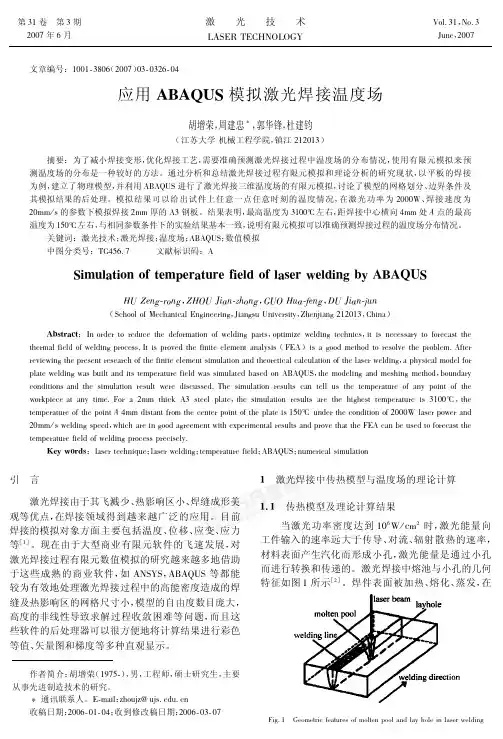
Modeling and Simulation 建模与仿真, 2014, 3, 17-24Published Online May 2014 in Hans. /journal/mos/10.12677/mos.2014.32004Simulation and Stress Analysis of U-Shaped Seam Welding Process Based on ABAQUSHongzhi Zhang1, Xuanyu Sheng2, Wei Hou31Daqing Oilfield Construction Group, Daqing2Institute of Nuclear and New Energy Technology, Tsinghua University, Beijing3China Jilin Petrochemical Company Refinery, JilinEmail: shxyzjh@Received: Mar. 6th, 2014; revised: Apr. 10th, 2014; accepted: Apr. 20th, 2014Copyright © 2014 by authors and Hans Publishers Inc.This work is licensed under the Creative Commons Attribution International License (CC BY)./licenses/by/4.0/AbstractAt present, there is a large-scale trend for chemical containers and reaction tower in the industry.In the large-scale equipment, U-shaped weld structure is widely used for splice weld of container wall. In this paper, by ABAQUS software, using plane models, U-shaped seam welding process was simulated, which was commonly used in pressure vessels and tower equipment. For welding ma-terial part, the “dead-actived elements” technique was applied in calculation, and the weld ma-terial part was divided into finer grid. The calculation model of the plane model was created using CATIA software, the software plug-in software was used to transform the model to directly read the ABAQUS software model. Calculation can be given to each welding temperature distribution and stress distribution. At the same time, the cooling after welding was considered in the welding process. Computer simulation gave the overall structure of the stress distribution and strain energy curve.KeywordsU-Weld, Welding Simulation, Finite Element, Stress基于ABAQUS的U型焊缝焊接过程模拟和应力分析张宏志1,盛选禹2,候巍31大庆油田建设集团,大庆市2清华大学核能与新能源技术研究院,北京市3中国吉林石化分公司炼油厂,吉林市Email: shxyzjh@收稿日期:2014年3月6日;修回日期:2014年4月10日;录用日期:2014年4月20日摘要目前,在工业界,化工容器、反应塔等有大型化的趋势。
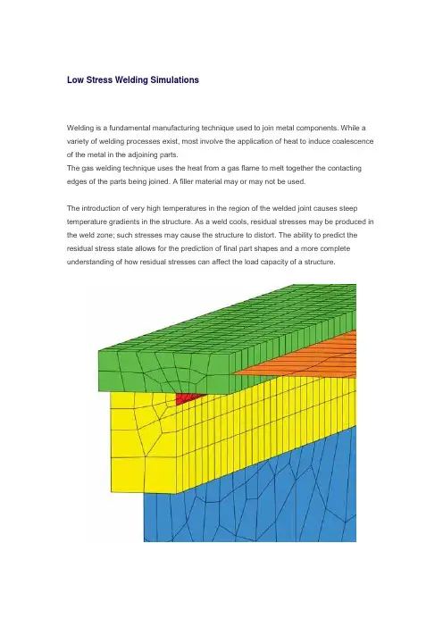
Low Stress Welding SimulationsWelding is a fundamental manufacturing technique used to join metal components. While a variety of welding processes exist, most involve the application of heat to induce coalescence of the metal in the adjoining parts.The gas welding technique uses the heat from a gas flame to melt together the contacting edges of the parts being joined. A filler material may or may not be used.The introduction of very high temperatures in the region of the welded joint causes steep temperature gradients in the structure. As a weld cools, residual stresses may be produced in the weld zone; such stresses may cause the structure to distort. The ability to predict the residual stress state allows for the prediction of final part shapes and a more complete understanding of how residual stresses can affect the load capacity of a structure.The finite element models described in this article represent structural beams. These structures are formed by welding plate sections together rather tha n producing the section directly in a mill. The cross-sectional size of these components can make direct manufacture impractical.The techniques discussed here are based on a generic model but are transferable to a range of applications.Finite Element Analysis ApproachThe simulation uses a sequentially coupled approach in which a thermal analysis is followed by a stress analysis. The temperature results from the thermal analysis are read into the stress analysis as loading to calculate the thermal stress effects. The thermal analysis makes use of ABAQUS user subroutines DFLUX, GAPCON, and FILM. The objective of the simulation is to predict post-weld deformation and residual stress distribution.Figure 1: Mesh of the structure being welded.The model is constructed using solid and shell elements. A solid representation is used in the weld area to ensure more accurate capture of the high solution gradients. Regions outside the weld zone, where thermal gradients are not as severe, are modeled with shell elements toreduce the overall model size. The transition between the shell and solid regions is achieved using tied contact for the thermal analysis and shell-to-solid coupling for the stress analysis. The mesh is shown in Figure 1 (left). The weld bead is shown in red.Thermal Analysis ProcedureThe thermal analysis is performed to calculate the heat transfer resulting from the thermal load of the moving torch. Three user subroutines are activated for the thermal analysis:DFLUX: Used to define the welding torch heat input as a concentrated flux. The heat source travels along the weld line to simulate the torch movement.GAPCON: Used to activate the conduction of heat between the deposited weld material and the parent materials once the torch has passed a given location.FILM: Similar to GAPCON in functionality, but used to activate film coefficients to simulate convective ambient cooling once the torch passes a given location.The simulation is run as a fully transient heat transfer analysis.Structural Analysis ProcedureThe structural analysis uses the thermal analysis (temperature) results as the loading. The objective of the structural analysis is to determine the stresses and strains induced in the weld region during the cooling transient. Boundary conditions are applied to restrain the system against rigid body motion.Figure 2: Nodal temperatures in a typical region of the weld as the torch traverses the weldline.Results and ConclusionTypical thermal results are shown in Figure 2 (left), which displays a contour of nodal temperature as the torch travels along the weld line.The weld is initialized at 1800° C, but no heat is allowed to transfer from the weld until the torch passes. As the torch passes a given point on the weld line, the flux input is initiated, resulting in a localized increase in temperature to more than 2000° C.Figure 3: Transient temperature profile at three points in the torch path.In addition, as the torch passes the same weld line point, conductive and convective heat transfer is activated, causing a rapid drop in temperature as thermal energy is transferred to the surrounding structure and environment.Figure 3 (right) shows the 35 s transient temperature profile at three points close to the start of the torch path. The peak temperature is reached when the torch is activated. A sharp temperature drop is observed after the torch passes.Figure 4: Von Mises stress in the weld region at t=35 s.The stress response of the structure is driven by the high thermal gradients. Figure 4 (left) and Figure 5 (below), respectively, show plots of the von Mises stress and the effective plastic strain approximately 35 s into the process.Figure 5: Effective plastic strain in the weld region at t=35 s.In conclusion, ABAQUS/Standard provides a set of general, flexible modeling tools that allow for the prediction of residual stresses and final shapes in welded components.。
Abaqus是一款广泛应用于工程领域的有限元分析软件,它通过建立虚拟模型,模拟真实的物理过程来解决工程问题。
在焊接领域,Abaqus可以用来模拟多道焊接过程。
本文将对Abaqus中多道焊接程序进行解释与分析。
一、多道焊接概述多道焊接是指在焊缝内部进行多次焊接的过程,通常用于大型结构的焊接,比如船舶、桥梁等。
多道焊接能够降低焊接残余应力和变形,提高焊接质量。
二、Abaqus中多道焊接的模拟1. 模型建立在Abaqus中进行多道焊接的模拟,首先需要建立焊接模型。
这包括定义焊接工艺参数、材料性质、焊接接头几何形状等。
2. 材料本构在多道焊接模拟中,材料的本构关系是非常重要的。
Abaqus提供了多种材料本构模型,可以根据具体的焊接材料选择合适的本构模型。
3. 热分析在多道焊接的过程中,焊缝内部会产生大量的热量。
Abaqus可以通过热分析模块,模拟焊接过程中的温度场分布、热应力等。
4. 结构分析除了热分析,结构分析也是多道焊接模拟中的重要步骤。
通过结构分析,可以得到焊接过程中的应力、变形等信息。
三、多道焊接模拟的应用1. 优化焊接工艺通过Abaqus的多道焊接模拟,可以对焊接工艺进行优化。
比如确定合适的焊接顺序、焊接参数,以达到最佳的焊接质量。
2. 预测残余应力和变形多道焊接模拟可以预测焊接过程中产生的残余应力和变形,帮助工程师更好地设计焊接结构,减少后期修复工作。
3. 焊缝设计通过Abaqus的多道焊接模拟,可以对焊缝进行优化设计,提高焊接连接的强度和稳定性。
四、多道焊接模拟的局限性尽管Abaqus可以进行多道焊接模拟,但也存在一些局限性。
比如对于大型结构、复杂工艺的模拟需要计算资源较大,同时需要对模型的建立和参数选择有一定的专业知识。
总结起来,Abaqus多道焊接程序可以帮助工程师模拟多道焊接过程,优化焊接工艺,预测残余应力和变形,提高焊接结构的质量和可靠性。
然而,工程师在使用Abaqus进行多道焊接模拟时需要注意模型的建立和参数选择,以及计算资源的消耗。

ABAQUS分析操作实例ABAQUS分析操作实例—For连接器行业Author:Dream flyDate: 2009-03-04操作流程介绍ABAQUS分析操作实例1.创建部件z ABAQUS CAD功能有限,对于复杂的几何模型一般都由其它CAD软件创建。
1.1 导入端子模型z在主菜单选择FileÆImportÆPart,在弹出的对话框中选择模型保存路径和格式类型。
部件导入对话框导入的端子模型1.2 创建解析刚性面z创建一解析刚性面以便对端子施加位移约束。
z在Module列表中选择Part模块,点击左侧工具区中的(Create Part),弹出Create Part 对话框,Type选择analytical rigid,把界面尺寸适当减小,点击Continue。
z在绘图环境中绘制一直线( ) ,然后点击三次中键确认,输入拉伸深度为1,完成解析刚性面创建。
z在主菜单选择ToolsÆReference point,创建一参考点来约束刚性面。
ABAQUS分析操作实例2.1 创建材料z 在Module 列表中选择Property 模块,点击左侧工具区中的(Create Material),弹出Edit Material 对话框,输入材料名称:C5210R-SH ,点击Mechanical ÆElasticity ÆElastic ,在数据表中设置材料Young’s Modulus 为110000,Poisson’s Ratio 为0.3,然后点击Mechanical ÆPlasticity ÆPlastic 输入两组材料塑性数据(710,0),(764,0.18),点击OK 。
2.1 创建截面属性z 点击左侧工具区中的(Create Section),点击Continue ,在弹出的Edit Section 对话框中,保持默认参数不变,点击OK 。
焊接中的温度变化过程是影响焊接质量的重要因素之一,准确的预测和计算温度的变化是控制其冶金和焊接应力应变变化的前提。
焊接是一个复杂的快速加热、冷却、凝固的过程,它涉及电弧物理、传质传热、冶金和力学的复杂过程。
焊接时各个过程相互影响、相互作用。
热量的传递有三种方式,分别是:热传导、热对流和热辐射。
焊接时,电弧热源是作用在一定的面积上把热能传递给工件的,此面积称为加热斑点,因此高斯热源的热流分布是一种比点热源更加实际的热源分布函数。
焊接热源通过加热斑点把热量传递给焊件,加热斑点上热量分布不均匀,中心热量多,边缘热量少。
ABAQUS 是一套功能强大的工程模拟的有限元软件,其解决问题的范围从相对简单的线性分析到许多复杂的非线性问题。
现采用ABAQUS对双枪焊接过程中温度场分布进行分析。
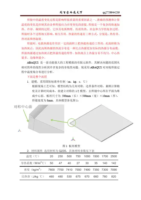
下面是整个流程1.建模,采用国际标准单位制(m,kg,s,℃)根据现场工艺可知,模型结构为几何对称,边界条件对称,兼顾计算精度及计算时间成本,故建立对称的1/2模型,去焊缝中心所在平面为堆成中心面。
板坯尺寸为500mm(长)×500mm(宽)×10mm(厚),焊缝宽度为8mm。
具体模型参见图1:图1 板坯模型2. 材料属性选用材料为Q235,具体材料参数见下表温度(℃)20 250 500 750 1000 1500 1700 2500导热系数(W/m2℃)50 47 40 27 30 35 140 142 密度(kg/m3)7800 7700 7410 7550 7490 7350 7300 7090比热容(J/kg ℃)460 480 530 675 670 660 780 820具体参数设置如图2所示。
图2 参数设置界面3. 装配,将板坯进行定位,为边界条件施加提供装配模型,对称面为YZ平面,焊道与Z轴平行,焊点沿Z轴移动,如图3所示。
图3 板坯组装图4.分析步设定,本为主要分析双枪焊接过程中,温度场变化情况,故选择分析类型为Heat transfer,根据实际工艺,选择Transient类型,分析步总时间根据现场工艺确定。
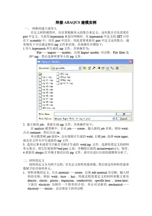
焊接ABAQUS建模实例一、网格的建立或导入在定义材料属性时,往往要根据单元的集合来定义,这些集合首先需要在part中定义。
当采用hypermesh来划分网格时,在hypermesh中定义的SET只存在于assembly中,而在part中没有,因此需要重新在part中定义这些集合,通常情况下可以通过修改inp文件来实现,具体操作步骤如下:1.导入hypermesh所生成的inp文件,具体操作为:File——import——models,出现Import models 对话框,File filter选择*.inp,然后选择所要导入的inp文件。
2. 建立新的job,重新生成inp文件,具体操作如下:在analysis模型树中,右击job——create,输入新的job名称,例如weld,点击continue,然后点击ok。
单击模型树job前的+,会出现刚才生成的weld,右键job,选择write input,就会在文件夹中生成新的inp文件。
3. 选用记事本或者写字板打开刚才生成的weld.inp文件,选择你需定义的材料单元集合,将它们复制到*end part之前,并删除后面的instance=part-1-1,保存。
4.重新用abaqus打开刚才修改后的inp文件,就可以进行后续的建模和分析了。
二、材料的定义材料的定义分为两个过程,首先定义材料性能参数,然后将这些材料性能参数赋予给具体的单元。
1.材料参数的定义。
右击material——create,出现edit material对话框,输入材料的名称,例如weld、base 、haz。
焊接过程需要定义的材料参数主要有density、elastic、plastic、expansion、conductivity、specific heat 、latent heat。
下面以elasticity为例作一个简单的介绍,单击对话框的mechanical——elasticity——elastic,会出现如下的对话框如果材料性能是温度的函数,把use temperature-dependent data 前的框选上。
Abaqus在焊接工艺仿真中的应用1. 简介焊接工艺是制造业中常见且重要的工艺之一,其仿真技术的发展对于提高焊接工艺的质量和效率具有重要意义。
而Abaqus作为一款广泛应用于工程领域的仿真软件,其在焊接工艺仿真中的应用也备受关注。
本文将从深度和广度两个方面展开,探讨Abaqus在焊接工艺仿真中的应用以及对焊接工艺的优化与改进。
2. Abaqus在焊接工艺仿真中的基本原理Abaqus作为有限元分析软件,其在焊接工艺仿真中的应用主要依靠其强大的非线性有限元分析能力。
通过建立焊接工艺的三维模型,包括焊接材料的性质、热源激励和工艺参数等,Abaqus可以对焊接过程中的温度场、应力场、变形等进行精确的仿真计算。
这种基于实际物理过程的仿真分析,可以帮助工程师深入理解焊接工艺中的复杂物理现象,为优化焊接工艺提供重要参考。
3. 深度探讨Abaqus在焊接工艺仿真中的应用在焊接工艺仿真中,Abaqus可以有效地模拟焊接过程中的热传导、相变、材料塑性变形等复杂物理现象。
通过对焊接接头和母材的热影响区、残余应力、变形等进行仿真分析,可以预测焊接工艺中可能出现的缺陷,如裂纹、变形过大等,从而指导工程师采取相应的措施进行改进。
基于Abaqus的仿真结果,还可以进行后续的焊接残余寿命评估、断裂韧性分析等工作,为焊接工艺的质量控制和安全评估提供支持。
4. 广度探讨Abaqus在焊接工艺仿真中的应用除了对焊接过程本身的仿真分析,Abaqus在焊接工艺中还可以应用于焊接接头的结构强度和疲劳寿命的评估。
通过建立焊接接头的有限元模型,结合载荷作用下的应力分析和损伤累积分析,可以预测焊接接头的疲劳寿命,为设计提供重要参考。
Abaqus还可以进行多工步的焊接工艺仿真,包括预热、多道次焊接等复杂工艺的仿真分析,为工程师提供全面的工艺优化方案。
5. 个人观点和理解在我看来,Abaqus在焊接工艺仿真中的应用极大地丰富了焊接工艺优化与改进的手段。
Abaqus软件掌握大部件焊接仿真的解决思路一、导读伴随着现代工业发展速度的不断加快,人们对工业产品需求增加,同时对其轻量化程度的要求也越来越高。
铝合金具有高的比强度、良好的机械性能以及耐腐蚀性等优点,已被广泛应用于许多焊接结构产品中,成为了现代工业用量最大和用途最广的轻量化金属材料,广泛应用在军工武器、汽车、轨道车辆、航空航天、机械制造、电工和船舶等领域在地铁车辆中,已大量采用铝合金车体。
常用的焊接方式为MIG 自动焊接。
焊接过程中加热和冷却过程的梯度温度场会导致焊后残余应力和焊接变形的产生。
焊接残余应力和焊接变形会降低产品尺寸精度和稳定性,严重影响轨道交通制造中焊接结构的制造和使用性能。
究其原因,在于当前的焊接应用中还存在很多落后的工艺方式,如何将现代的焊接数值仿真技术应用于传统的焊接工艺,利用先进的计算机数值模拟技术改造传统的焊接工艺,对加速我国焊接信息化与工业化的融合有着非常重要的意义。
焊接数值模拟技术的发展是随着焊接实践经验的积累,有限元数值模拟技术,计算机技术等的发展而逐步开始的。
焊接工艺的仿真,主要是针对焊接温度场,残余应力,变形等方面改善焊接部件的制造质量,提高产品服役性能,优化焊接顺序等工艺过程。
本文利用大型商用有限元分析软件ABAQUS对某地铁车辆侧墙总成焊接进行仿真。
研究在焊接过程中侧墙的变形情况,并测试在施加不同反变形的工况下侧墙焊后整体的平面度。
最后将仿真结果与实件焊接进行对比验证,为现场焊接工艺的指定提供理论指导。
二、地铁侧墙总成焊接现象描述某地铁项目中车体侧墙大部件采用搅拌摩擦焊墙板单元,该单元在焊接完成后与侧墙边梁经过MIG自动焊焊接而成,要求MIG自动焊后整体平面度1.5mm/m,结构示意图如下:图1 焊接区域图(1-边梁 2-墙板单元)图2 焊接示意图焊接时,先焊接第一道焊缝,将边梁正面和侧墙正面紧压在工装上,主要焊接参数为I=210,U=19.7,v=40cm/min。
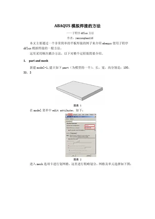
ABAQUS模拟焊接的方法——子程序dflux方法作者:yanzongbao110本文主要通过一个非常简单的平板焊接的例子来介绍abaqus使用子程序dflux模拟焊接的一般方法。
这里采用顺次耦合方法,以下对整个过程做简要介绍。
1. part and mesh新建model-1,建立如下part(为模型的一半),长,宽,高分别是:100,50,5图表 1在model菜单中edit attibute,如下:图表 2进入mesh选项卡进行划网格,这里进行粗略划分,网格及单元选择如下图:图表 3图表 42. material在material选项卡里新建材料,这里假设焊缝与母材的材料一样,所以只建立一种材料。
材料包括以下部分(本例中没有应用latent heat):图表 5图表 63. assembly在assembly选项中,进行装配。
如下:图表 7建立不同的集合及表面,以便后面保用。
建立set-allnode,如下图图表 8建立surface-rad,如下图。
注意左侧面为对称面,不选择。
图表 94.创建分析步创建两个热传导分析步,分别是焊缝加热和冷却过程。
如下图:图表 10定义第一个分析步:(a) (b)图表 11定义第二个分析步:(a) (b)图表 125. 创建interaction在interaction中创建对流和辐射边界条件如下:(a) (b)图表 13(a) (b)图表 146. 边界条件建立首先建立预定义场,定义初始温度为20℃,选择集合set-allnode,如下图:(a) (b)图表 15建立body heat flux载荷,选择整个实体,设置为user-defined,如下图:(a) (b)图表 167. 建立名称为weld-thermal的job,并输出.inp。
图表 178. 编写dflux子程序其中热源用的是双椭球热源,具体可参考相关文献。
q=UIη,这里η代表效率。
x0,y0,z0定义热源的起始点,a,b,c定义热源的三个半轴,v定义焊接速度。
基于ABAQUS 的焊接结构力学行为有限元分析摘要:为了避免钢结构大棚在恶劣气候期间发生安全事故,提高Q235B 抗风雪和抗振动能力,分析在结构承载条件下的极限形变数据。
利用ABAQUS 对对Q235B 钢管手工电弧焊焊接成形的连跨型网架结构进行建模,研究自重环境因素影响下焊接结构的非线性承载能力,通过模型有限元分析和计算结果分析结构的可靠性。
结果表明:应力最大值出现在网架结构靠近约束的部分,达到5.499×10⁻⁴MPa ,远小于Q235B 屈服强度;等效塑性应变量为0,即表明该结构无塑性变形量,处于弹性状态。
该设计方案完全符合实际要求。
关键词:网架结构;Q235B ;ABAQUS ;有限元分析法中图分类号:TG404文献标识码:A 文章编号:2095-0438(2021)03-0144-03(福建商学院信息工程学院福建福州350506)詹友金∗∗∗第41卷第3期绥化学院学报2021年3月Vol.41No.3Journal of Suihua UniversityMar .2021收稿日期:2020-08-21作者简介:詹友金(1965-),男,福建福州人,福建商学院信息工程学院讲师,高级工程师,研究方向:现场施工管理及工程造价。
连跨型网架结构具有良好建设周期短、结构质量轻以及造价便宜等特点,在农业、工业以及建造业得到良好的工程应用[1]。
尤其是作为塑料大棚的支持结构件,通过节点连接而成的一种空间杆系结构,其外形呈曲面状为网壳,呈平板状的为网架结构[2]。
区别于一般的网架结构,连跨型网架结构跨度较大,由于外部环境因素(例如暴雨、暴雪、大风等天气)和内部因素(例如负载过重、跨度过大等)的影响导致容易出现坍塌事故发生[3,4]。
所以,在设计连跨型网架结构过程中更加需要进行考虑结构材料的抗压能力和结构的负载能力。
在本文采用非线性数值分析软件ABAQUS 对焊接成形的连跨型网架结构进行受力分析,进行自重环境因素影响下焊接结构的非线性承载能力分析。
标:q焊接温度曲线:理解、应用与优化
q是一种广泛应用于工程领域的有限元分析,可以模拟复杂结构的热力学行为。
在焊接过程中,温度分布对最终焊接质量和性能具有重要影响。
本文将以q焊接温度曲线为切入点,探讨焊接过程中温度的变化规律、应用方法以及优化策略。
第一部分:理解q焊接温度曲线
本部分将介绍焊接温度曲线的基本概念和意义,解释q如何计算焊接过程中的温度分布。
文中将阐述热传导方程和材料性质对焊接温度的影响,并结合实例验证q的可靠性及适用性。
第二部分:应用q焊接温度曲线
焊接温度曲线可用于预测焊接过程中的温度分布,对焊缝形成和变形进行分析。
本部分将介绍如何通过q生成焊接温度曲线,并针对不同材料和焊接方法,探讨温度分布的变化规律。
还将探讨如何利用温度曲线分析焊缝的残余应力及热影响区的尺寸。
第三部分:q焊接温度曲线的优化策略
为实现优质焊接,需要通过优化焊接参数来控制温度分布。
本部分将介绍如何通过q 分析工具,优化焊接过程中的热输入和热输出。
通过设计合适的预热和冷却过程,以及优化焊接速度和功率等参数,可以达到最佳温度分布和焊缝质量。
结论:
通过分析q焊接温度曲线,我们能够深入了解焊接过程中的温度变化规律,预测焊接质量以及残余应力分布。
通过适当调整焊接参数,我们可以优化焊接过程,高焊缝的质量和性能。
q作为一种强大的工程仿真工具,可以为焊接工艺的设计和优化供重要的支持。
在工程实践中,结合q焊接温度曲线的分析,我们可以更好地实现高质量的焊接工艺。
Abaqus模拟焊接Abaqus模拟焊接—基于Fortran的热源子程序1概述Abaqus的二次开发一般用Python,而Abaqus中应用到的子程序(包括材料和载荷等)用Fortran编写。
Abaqus的子程序接口比较多,在模拟焊接时对热源的描述只能采用子程序的方式进行加载。
2热源焊接时的热源其实是比较复杂的,但是为了便于计算,比较常用的做法是将热源采用高斯函数的形式进行描述。
其形式如下,分别是直角坐标系下和极坐标系下。
这个方程的坐标值是基于热源中心的坐标,热源形式如图1所示:图1 热源分布3建模(1)Part建立一个矩形平板如图2。
图2 Part(2)Property定义材料属性,热导率(Conductuvity),密度(Density),弹性模量(Elastic),膨胀系数(Expansion)、塑性参数(Plastic)、比热容(Specific Heat)。
图3 Property(3)Assembly建立组件。
(4)Step焊接模拟如果只求温度场,那么就建立Heat Transfer载荷步,如果需要热应力,那么就需要建立耦合分析步,Couple temp-displacement 。
定义两个载荷步分别是焊接过程和冷却过程,同时打开大变形。
图4 Step根据需要设置Fieldoutput输出场数据和历史输出数据History Output.(5)Interaction平板的所有表面与外界存在对流传热,需要定义对流传热属性,对流传热系数Film condition,定义的时候还需要指定外界的温度。
图5 Interaction(6)Load焊接热源属于体热源,需要定义Body heat flux,热源只作用于第一个载荷步,体热源的作用对象是所有的体,不单单是焊接那一部分。
定义热源时选择用户自定义(User-defined),由子程序加载。
图 6 Heat flux然后施加约束。
再然后通过Predefined Field Manager管理器定义初始温度。
Abaqus焊接模拟分析程序(包括应力场和温度场)Abaqus焊接模拟分析程序(包括应力场和温度场)【我的硕士论文的一部分】求解温度场!上表面上没有对流换热边界条件!单位制:米、秒、摄氏度!/CLEAR,START/FILNAME,temp,0/COM,ANSYS RELEASE10.0 UP20050718 00:09:5211/26/2007/CONFIG, NRES, 5000/PREP7/VIEW,1,1,2,3/ANG,1/REP,FAST!*!======================================== ========================================= ==============!指定单元ET,1,SOLID70!*!*!======================================== ========================================= ==============!材料属性!======================================== =============================================!316LMPTEMP,,,,,,,,MPTEMP,1,0MPDATA,DENS,1,,7850MPTEMP,,,,,,,,MPTEMP,1,20MPTEMP,2,300MPTEMP,3,900MPTEMP,4,1400MPTEMP,5,2000MPDATA,KXX,1,,18.6MPDATA,KXX,1,,21.4MPDATA,KXX,1,,28.4MPDATA,KXX,1,,33.9MPDATA,KXX,1,,48MPTEMP,,,,,,,,MPTEMP,1,20MPTEMP,2,600MPTEMP,3,800MPTEMP,4,1400MPTEMP,5,2000MPDATA,C,1,,502MPDATA,C,1,,612MPDATA,C,1,,635MPDATA,C,1,,659MPDATA,C,1,,670MPTEMP,,,,,,,,MPTEMP,1,20MPTEMP,2,1300MPTEMP,3,1410MPTEMP,4,1440MPTEMP,5,1550MPTEMP,6,2000 MPDATA,ENTH,1,,7.88e7 MPDATA,ENTH,1,,6.131e9 MPDATA,ENTH,1,,7.347e9 MPDATA,ENTH,1,,9.145e9MPDATA,ENTH,1,,1.03e10MPDATA,ENTH,1,,1.272e10!======================================== ========================================= ==============!定义常量WidthBase=0.025!宽度HeightBase=0.02!基底高度Length=0.09!长度WidthClad=0.0015!宽度HeightDeposition=0.00375!覆层高度Layer=15!层数HeightClad=HeightDeposition/layerdt=0.0001!小量Temp=20!环境温度InitTemp=300!初始温度CoffConv=30!对流换热系数!======================================== ========================================= ==============!定义常量Velocity=0.003!扫描速度StepDis=0.0015!每个载荷步位移LaserPower=700!激光功率Radius=0.0015!激光光斑半径Area=3.14159265*(Radius**2)!激光光斑面积Factor=0.3!吸收因子StepTime=StepDis/Velocity!每个载荷步时间TotalTime=(Length+Radius*2)/Velocity!载荷持续时间(扫描一层) StepNum=(Length+Radius*2)/StepDis!载荷步数!======================================== =======================================================!建模BLOCK,0,Length,0,-0.0066,0,WidthClad,BLOCK,0,Length,0,-0.0066,WidthClad,0.0067 BLOCK,0,Length,-0.0066,-HeightBase,0,WidthClad,K, ,0,0,WidthBase,K, ,Length,0,WidthBase,K, ,0,-HeightBase,WidthBase,K, ,Length,-HeightBase,WidthBase,V, 16, 13, 27, 25, 15, 14,28, 26V, 24, 21, 27, 13, 23, 22,28, 14BLOCK,0,Length,0,HeightDeposition,0,WidthClad,VGLUE,ALLNUMCMP,ALL!======================================== ========================================= ==============!划分网格LSEL, S, LOC, Y, dt, HeightDeposition-dt,!高度方向LESIZE, ALL, , , Layer,LSEL,S,LOC,Y,-DT,-0.0066+DTLSEL,R,LOC,X,0LESIZE,ALL,,,4,2LSEL,S,LOC,Y,-DT,-0.0066+DTLSEL,R,LOC,X,LengthLESIZE,ALL,,,4,0.5LSEL,S,LOC,Y,-0.0066-DT,-HeightBase+DT LSEL,R, LOC, Z, 0, WidthBase-DT,LESIZE,ALL,,,4,2LSEL,S,LOC,Y,-0.0066-DT,-HeightBase+DT LSEL,R, LOC, Z, WidthBase,LESIZE,ALL,,,4,0.5LSEL, S, LOC, X, dt,Length-dt,!长度方向LESIZE, ALL, , , Length/StepDis,LSEL, S, LOC, Z, dt, WidthClad-dt,!宽度方向LESIZE, ALL, , , 1,LSEL,S,LOC,Z,WidthClad+DT,0.0067-DTLESIZE,ALL,,,4,LSEL,S,LOC,Z,0.0067+DT,WidthBase-DT LSEL,R,LOC,Y,-DT,-HeightBaseLESIZE,ALL,,,4,2LSEL,S,LOC,Z,0.0067+DT,WidthBase-DTLSEL,R,LOC,Y,0LESIZE,ALL,,,4,0.5VSEL,S,LOC,Y,0,HeightDeposition!网格划分TYPE,1MAT,1MSHAPE,0,3DMSHKEY,1VMESH,ALLVSEL,S,LOC,Y,-1,0!网格划分TYPE,1MAT,1MSHAPE,0,3DMSHKEY,1VMESH,ALLALLSEL,ALL!======================================== ========================================= ==============!基底边界条件、初始条件NSEL, S, LOC, Y, -HeightBase,0 !基底初始温度IC,ALL,TEMP,InitTempALLSEL,ALLNSEL, S, LOC, Y, -HeightBase,0 !基底侧面,换热边界条件NSEL, R, LOC, Z, WidthBaseSF, ALL, CONV, CoffConv, TempALLSEL,ALLNSEL, S, LOC, Y, -HeightBase,0 !基底左端面,换热边界条件NSEL, R, LOC, X, 0SF, ALL, CONV, CoffConv, TempALLSEL,ALLNSEL, S, LOC, Y, -HeightBase,0 !基底右端面,换热边界条件NSEL, R, LOC, X, LengthSF, ALL, CONV, CoffConv, TempALLSEL,ALLNSEL, S, LOC, Y,!基底上表面,换热边界条件NSEL, R, LOC, Z, WidthClad, WidthBase SF, ALL, CONV, CoffConv, TempALLSEL,ALLFINISH/SOLU!======================================== ========================================= ==============!瞬态分析参数设置ANTYPE,4!分析类型:瞬态!*TRNOPT,FULL!求解方法:完全的N-R方法LNSRCH, on!*!DELTIM,0.01,0.001,0.05!载荷子步(默认子步时间步长、最小、最大)——载荷步为0.333NSUBST, 4CNVTOL,HEAT, ,0.01,2,0.000001,!收敛准则:控制热流OUTRES,NSOL,LAST!结果输出:所有!======================================== ========================================= ==============!杀死单元NSEL, S, LOC, Y, 0, HeightDeposition !杀死熔覆层单元ESLN, S, 1, ALLEKILL,ALLALLSEL,ALLESEL,S,LIVEEPLOTESEL,S,LIVE!激活单元的上表面,指定为对流换热边条NSLE,S,1NSEL,R,LOC,Y,0NSEL,R,LOC,Z,0,RadiusSF,ALL,CONV,CoffConv,TempALLSEL,ALL!======================================== =======================================================!预热*DO, i, 1, 2m=mod(i,2)*IF,m,EQ,1,THEN!如果为奇数层,向右扫描*DO, k, 1, StepNum, 1TIME,TotalTime*(i-1)+StepTime *k !载荷步结束时间KBC,1!载荷步内载荷随时间分布:常数LeftX=StepDis*(k-1)RightX=StepDis*kNSEL, S, LOC, Y, 0ESEL, S, LIVEESLN, R, 0NSLE, S, 1NSEL, R, LOC, x,RightX-2*Radius, RightXNSEL, R, LOC, Z, 0, Radius!激活单元的上表面,加热流密度ESLN, S, 1SFE, ALL, 4, HFLUX, , LaserPower*Factor/Area, , ,ALLSEL, ALLSOLVESAVESFEDELE,ALL,4,HFLUX!删除热流密度载荷ALLSEL, ALLESEL,S,LIVE!激活单元的上表面,指定为对流换热边条NSLE,S,1NSEL,R,LOC,Y,0NSEL, R, LOC, x, LeftX-2*StepDis, RightX-2*StepDisNSEL, R, LOC, Z, O, RadiusSF,ALL,CONV,CoffConv,TempALLSEL,ALLESEL,S,LIVEEPLOT*ENDDO*ELSE!如果为偶数层,向左扫描*DO, k, 1, StepNum, 1TIME,TotalTime*(i-1)+StepTime *k !载荷步结束时间KBC,1!载荷步内载荷随时间分布:常数LeftX=Length-StepDis*kRightX=Length-StepDis*(k-1)NSEL, S, LOC, Y, 0ESEL, S, LIVEESLN, R, 0NSLE, S, 1NSEL, R, LOC, x,RightX-2*Radius, RightXNSEL, R, LOC, Z, 0, Radius!激活单元的上表面,加热流密度ESLN, S, 1SFE, ALL, 4, HFLUX, , LaserPower*Factor/Area, , ,ALLSEL, ALLSOLVESAVESFEDELE,ALL,4,HFLUX!激活单元的上表面,删除载荷ALLSEL, ALLESEL,S,LIVE!激活单元的上表面,指定为对流换热边条NSLE,S,1NSEL,R,LOC,Y,0NSEL, R, LOC, x, LeftX-2*StepDis, RightX-2*StepDisNSEL, R, LOC, Z, O, RadiusSF,ALL,CONV,CoffConv,TempALLSEL,ALLESEL,S,LIVEEPLOT*ENDDO*ENDIF*ENDDOESEL,S,LIVEEPLOT!======================================== =======================================================!熔覆*DO, i, 1, Layer, 1m=mod(i,2)*IF,m,EQ,1,THEN!如果为奇数层,向右扫描*DO, k, 1, StepNum, 1TIME,TotalTime*(i+1)+StepTime *k !载荷步结束时间KBC,1!载荷步内载荷随时间分布:常数LeftX=StepDis*(k-1)RightX=StepDis*kNSEL, S, LOC, Y,HeightDeposition/Layer*(i-1),HeightDeposition/Layer*iNSEL, R, LOC, x, LeftX, RightXESLN, S, 1EALIVE,ALLALLSEL, ALLNSEL, S, LOC, Y,HeightDeposition/Layer*(i-1),HeightDeposition/Layer*iNSEL, R, LOC, x,RightX-2*Radius, RightXNSEL, R, LOC, Z, 0, Radius!激活单元的上表面,加热流密度ESLN, S, 1SFE, ALL, 4, HFLUX, , LaserPower*Factor/Area, , ,ALLSEL, ALLESEL,S,LIVE!激活单元的表面,如果包含左端面,指定为对流换热边条NSLE,S,1NSEL,R,LOC,X,0NSEL,R,LOC,Y,HeightDeposition /Layer*(i-1), HeightDeposition/Layer*iSF,ALL,CONV,CoffConv,TempALLSEL,ALLESEL,S,LIVE!激活单元的表面,如果包含右端面,指定为对流换热边条NSLE,S,1NSEL,R,LOC,X,LengthNSEL,R,LOC,Y,HeightDeposition/Layer*(i-1), HeightDeposition/Layer*iSF,ALL,CONV,CoffConv,TempALLSEL,ALLESEL,S,LIVE!激活单元的侧面,指定为对流换热边条NSLE,S,1NSEL,R,LOC,Z,WidthCladNSEL,R,LOC,Y,HeightDeposition /Layer*(i-1), HeightDeposition/Layer*iSF,ALL,CONV,CoffConv,TempALLSEL,ALLSOLVESAVESFEDELE,ALL,4,HFLUX!删除热流密度载荷ALLSEL, ALLESEL,S,LIVE!激活单元的上表面,指定为对流换热边条NSLE,S,1NSEL,R,LOC,Y,HeightDeposition/Layer*iNSEL, R, LOC, x, LeftX-2*StepDis, RightX-2*StepDisSF,ALL,CONV,CoffConv,TempALLSEL,ALLNSEL,S,LOC,Y,HeightDeposition /Layer*(i-1) !激活单元的下表面,删除对流换热边条ESEL, S, LIVEESLN, R, 0NSLE, S, 1NSEL, R, LOC, x, LeftX-2*StepDis,RightX-2*StepDisNSEL, R, LOC, Z, 0, RadiusNSEL, U, LOC, Y,HeightDeposition/Layer*iESLN, S, 1NSEL, R, LOC,Y,HeightDeposition/Layer*(i-1)SFDELE, ALL, CONVALLSEL,ALLESEL,S,LIVEEPLOT*ENDDO*ELSE!如果为偶数层,向左扫描*DO, k, 1, StepNum, 1TIME,TotalTime*(i+1)+StepTime *k !载荷步结束时间KBC,1!载荷步内载荷随时间分布:常数LeftX=Length-StepDis*kRightX=Length-StepDis*(k-1)NSEL, S, LOC, Y,HeightDeposition/Layer*(i-1),HeightDeposition/Layer*iNSEL, R, LOC, x, LeftX, RightXESLN, S, 1EALIVE,ALLALLSEL, ALLNSEL, S, LOC, Y,HeightDeposition/Layer*(i-1),HeightDeposition/Layer*iNSEL, R, LOC, x, LeftX,LeftX+2*RadiusNSEL, R, LOC, Z, 0, Radius!激活单元的上表面,加热流密度ESLN, S, 1SFE, ALL, 4, HFLUX, , LaserPower*Factor/Area, , ,ALLSEL, ALLESEL,S,LIVE!激活单元的表面,如果包含左端面,指定为对流换热边条NSLE,S,1NSEL,R,LOC,X,0NSEL,R,LOC,Y,HeightDeposition /Layer*(i-1), HeightDeposition/Layer*iSF,ALL,CONV,CoffConv,TempALLSEL,ALLESEL,S,LIVE!激活单元的表面,如果包含右端面,指定为对流换热边条NSLE,S,1NSEL,R,LOC,X,LengthNSEL,R,LOC,Y,HeightDeposition /Layer*(i-1), HeightDeposition/Layer*iSF,ALL,CONV,CoffConv,TempALLSEL,ALLESEL,S,LIVE!激活单元的侧面,指定为对流换热边条NSLE,S,1NSEL,R,LOC,Z,WidthCladNSEL,R,LOC,Y,HeightDeposition /Layer*(i-1), HeightDeposition/Layer*iSF,ALL,CONV,CoffConv,TempALLSEL,ALLSOLVESAVESFEDELE,ALL,4,HFLUX!激活单元的上表面,删除载荷ALLSEL, ALLESEL,S,LIVE!激活单元的上表面,指定为对流换热边条NSLE,S,1NSEL,R,LOC,Y,HeightDeposition/Layer*iNSEL, R, LOC, x, LeftX+2*StepDis, RightX+2*StepDisSF,ALL,CONV,CoffConv,TempALLSEL,ALLNSEL,S,LOC,Y,HeightDeposition /Layer*(i-1) !激活单元的下表面,删除对流换热边条ESEL, S, LIVEESLN, R, 0NSLE, S, 1NSEL, R, LOC, x, LeftX+2*StepDis,RightX+2*StepDisNSEL, R, LOC, Z, 0, RadiusNSEL, U, LOC, Y,HeightDeposition/Layer*iESLN, S, 1NSEL, R, LOC,Y,HeightDeposition/Layer*(i-1)SFDELE, ALL, CONVALLSEL,ALLESEL,S,LIVEEPLOT*ENDDO*ENDIF*ENDDOESEL,S,LIVEEPLOT!======================================== =======================================================!冷却!======================================== ======================================!~100s*DO, k, 1, 2, 1TIME,TotalTime*(Layer+2)+50*k!载荷步结束时间NSUBST, 5KBC, 1SOLVESAVE*ENDDO!======================================== ======================================!~1000s*DO, k, 1, 9, 1TIME,TotalTime*(Layer+2)+100+ 100*k!载荷步结束时间NSUBST, 5KBC, 1SOLVESAVE*ENDDO!======================================== ======================================!~3000s*DO, k, 1, 10, 1TIME,TotalTime*(Layer+2)+1000 +200*k!载荷步结束时间NSUBST, 5KBC, 1SOLVESAVE*ENDDO!==============================================================================!~10000s*DO, k, 1, 14, 1TIME,TotalTime*(Layer+2)+3000 +500*k!载荷步结束时间NSUBST, 5KBC, 1SOLVESAVE*ENDDOFINISH【我的硕士论文的一部分】求解应力场!修改速度、时间子步步长、载荷文件位置!如果修改基底的热膨胀系数,要修改宏文件!单位制:米、秒、摄氏度/CLEAR,START/FILNAME,stress,0/COM,ANSYS RELEASE10.0 UP20050718 20:15:5209/10/2007/CONFIG, NRES, 5000/PREP7/PAGE, 1000, , 1000,/VIEW,1,1,2,3/ANG,1/REP,FAST!*!======================================== ========================================= ==============!指定单元ET,1,45!*!*!======================================== ========================================= ==============!材料属性!======================================== =============================!316LMPTEMP,,,,,,,,MPTEMP,1,0MPDATA,DENS,1,,7850MPTEMP,,,,,,,,MPTEMP,1,0MPDATA,ALPX,1,,1.75E-005MPTEMP,,,,,,,,MPTEMP,1,20MPTEMP,2,300MPTEMP,3,600MPTEMP,4,900MPTEMP,5,1300MPDATA,EX,1,,2.0E+11MPDATA,EX,1,,1.7E+11 MPDATA,EX,1,,1.5E+11MPDATA,EX,1,,5.0E+10 MPDATA,EX,1,,0.4E+10MPDATA,PRXY,1,,0.25MPDATA,PRXY,1,,0.25MPDATA,PRXY,1,,0.25MPDATA,PRXY,1,,0.25MPDATA,PRXY,1,,0.25TB,KINH,1,5,4,0TBTEMP,20TBPT,,0,0TBPT,,7E-4,1.4E8TBPT,,0.0012,1.83E8TBPT,,0.1,2.16E9TBTEMP,300TBPT,,0,0TBPT,,5.5E-4,9.35E7TBPT,,0.0012,1.27E8TBPT,,0.1,1.84E9TBTEMP,600TBPT,,0,0TBPT,,3.2E-4,4.8E7TBPT,,0.0012,7.19E7TBPT,,0.1,1.54E9TBTEMP,900TBPT,,0,0TBPT,,2.5E-4,1.25E7TBPT,,0.0012,5.1E7TBPT,,0.1,5.45E8TBTEMP,1300TBPT,,0,0TBPT,,2.5E-4,1E6TBPT,,0.00375,1.13E7TBPT,,0.1,7.05E7!======================================== =============================!A3ExpandCoeff=1.75E-005!structural->nonlinear->inelastic->rate independent->kinematic hardening plasticity->mises plasticity->bilinear!======================================== ========================================= ==============!定义常量WidthBase=0.025!宽度HeightBase=0.02!基底高度Length=0.09!长度WidthClad=0.0015!宽度HeightDeposition=0.00375!覆层高度Layer=15!层数HeightClad=HeightDeposition/layerdt=0.0001!小量Temp=20!环境温度InitTemp=300!初始温度CoffConv=30!对流换热系数!======================================== ========================================= ==============!定义常量Velocity=0.003!扫描速度StepDis=0.0015!每个载荷步位移LaserPower=700!激光功率Radius=0.0015!激光光斑半径Area=3.14159265*(Radius**2)!激光光斑面积Factor=0.3!吸收因子StepTime=StepDis/Velocity!每个载荷步时间TotalTime=(Length+Radius*2)/Velocity!载荷持续时间(扫描一层) StepNum=(Length+Radius*2)/StepDis!载荷步数!======================================== =======================================================!建模BLOCK,0,Length,0,-0.0066,0,WidthClad,BLOCK,0,Length,0,-0.0066,WidthClad,0.0067 BLOCK,0,Length,-0.0066,-HeightBase,0,WidthClad,K, ,0,0,WidthBase,K, ,Length,0,WidthBase,K, ,0,-HeightBase,WidthBase,K, ,Length,-HeightBase,WidthBase,V, 16, 13, 27, 25, 15, 14,28, 26V, 24, 21, 27, 13, 23, 22,28, 14BLOCK,0,Length,0,HeightDeposition,0,WidthClad,VGLUE,ALLNUMCMP,ALL!======================================== ========================================= ==============!划分网格HeightDeposition-dt,!高度方向LESIZE, ALL, , , Layer,LSEL,S,LOC,Y,-DT,-0.0066+DTLSEL,R,LOC,X,0LESIZE,ALL,,,4,2LSEL,S,LOC,Y,-DT,-0.0066+DTLSEL,R,LOC,X,LengthLESIZE,ALL,,,4,0.5LSEL,S,LOC,Y,-0.0066-DT,-HeightBase+DT LSEL,R, LOC, Z, 0, WidthBase-DT,LESIZE,ALL,,,4,2LSEL,S,LOC,Y,-0.0066-DT,-HeightBase+DT LSEL,R, LOC, Z, WidthBase,LESIZE,ALL,,,4,0.5Length-dt,!长度方向LESIZE, ALL, , , Length/StepDis,LSEL, S, LOC, Z, dt, WidthClad-dt,!宽度方向LESIZE, ALL, , , 1,LSEL,S,LOC,Z,WidthClad+DT,0.0067-DTLESIZE,ALL,,,4,LSEL,S,LOC,Z,0.0067+DT,WidthBase-DT LSEL,R,LOC,Y,-DT,-HeightBaseLESIZE,ALL,,,4,2LSEL,S,LOC,Z,0.0067+DT,WidthBase-DTLSEL,R,LOC,Y,0LESIZE,ALL,,,4,0.5VSEL,S,LOC,Y,0,HeightDeposition!网格划分TYPE,1MAT,1MSHAPE,0,3DMSHKEY,1VMESH,ALLVSEL,S,LOC,Y,-1,0!网格划分TYPE,1MAT,1MSHAPE,0,3DMSHKEY,1VMESH,ALLALLSEL,ALLVSEL,S,LOC,Y,-0.0066-DT,-HeightBase+DT!删除热影响区外的单元VSEL,A,LOC,Z,0.0067+DT,WidthBase-DTVCLEAR,ALLVDELE,ALL, , ,1ALLSEL,ALLFINISH!======================================== ========================================= ==============!瞬态分析参数设置/SOLANTYPE,4!分析类型:瞬态TRNOPT,FULL!求解方法:对于材料非线性,这是唯一的方法NLGEOM,on!大变形分析LNSRCH, onNSUBST, 4NEQIT,30CNVTOL,U,,0.05,2,,!收敛准则:控制位移CNVTOL,F,,0.01,2,!收敛准则:控制力OUTRES,NSOL,LAST!结果输出:TREF, Temp!======================================== ========================================= ==============!杀死单元NSEL, S, LOC, Y, 0, HeightDeposition !杀死熔覆层单元ESLN, S, 1EKILL,ALLALLSEL,ALLESEL,S,LIVEEPLOTNSEL,S,LOC,Z,0!对称边条(相当于三个约束,UZ,ROTX,ROTY)D,ALL,UZ,0NSEL,S,LOC,Y,-0.0066!固定中心点(增加两个约束,UX,UY)NSEL,R,LOC,Z,0NSEL,R,LOC,X,length/2D,ALL,ALL,0NSEL,S,LOC,Y,-0.0066,0!固定中心线(增加一个约束,ROTZ)NSEL,R,LOC,Z,0NSEL,R,LOC,X,length/2D,ALL,UX,0ALLSEL,ALLSAVE!======================================== =======================================================!熔覆*DO,m,1,Layerk=mod(m,2)*IF,K,EQ,1,THEN*DO,n,1,StepNum,KBC,0TIME,TotalTime*(m-1)+StepTime*nLeftX=StepDis*(n-1)。
ABAQUS焊点模拟方法Abaqus中焊点模拟,常用的是fastener方式,单元类型为*CONN3D2。
在Hypermesh 中,生成焊点操作步骤为:(1)进入焊点面板:1D>connectors>spot;(2)将焊点类型切换至fastener;(3)从CATIA中导入焊点文件(制作为焊核几何中心的点);(4)在num layers中根据焊点的层数,选择tatal 2为两层焊点,total 3为三层焊点;(5)选取焊点后,creat焊点焊点生成后,需要设置焊点属性。
焊点属性分为两个部分,一部分用于指定connector 的属性,即定义*CONN3D2单元的类型;另一部分用于设置焊点的尺寸。
(1)指定*CONN3D2属性为焊点:*CONNECTOR SECTION,ELSET=HMprop_HM_C_1JOIN,ALIGN或者,*CONNECTOR SECTION,ELSET=HMprop_HM_C_1BEAM,(2)指定焊点尺寸:*FASTENER PROPERTY, NAME = HM_P_13.0 ,以上设置完成后,即完成焊点模拟。
在Abaqus中,有多种Connector连接方式。
Join,模拟球铰,只约束三个方向的平动自由度,释放三个转动自由度;Align,仅约束三个转动自由度方向,释放三个平动自由。
因此,Join,Align组合在一起,就可以约束两个点之间的三个平动自由度和三个转动自由度。
而Beam,则能够同时约束两个点的三方向平动自由度和转动自由度。
因此,Beam和Join,Align组合产生的约束效果是一样的。
在Abaqus中,模拟焊点的方法有多种。
1.直接通过刚性单元,如KINCOUP,BEAM等单元来模拟。
2.通过connector的方法来模拟焊点是一个高效的方法。
不考虑模型的计算精度因素,单从建模效率来讲。
采用方法1,需要节点之间对齐,这对于拥有4000~6000焊点的白车身而言,工作量太大了。
采用Abaqus软件进行焊接模拟分析步骤:1建立有限元模型,定义材料参数,划分网格:考虑到abaqus软件焊接模拟分析焊接路径的施加是依赖于方程控制,建议选择模型时慎重,当然如果自我感觉建立复杂路径方程不在话下,可以忽略我的善意的提醒。
定义材料参数时,要记住准备两套,一个用于夏天清凉装,一个用于冬天的臃肿装?,当然不是,是一套用于传热分析,包括thermal conductivity,specific heat,当然还有一个dencity;另外一个套用于热应力分析,包括thermal expansion,elasticity,plasticity。
这些材料参数都要是与温度相关的。
别告诉我你不知道,怎么搞这些参数,因为我也不知道,哈哈!至于网格怎么划分,我就不说了,大家都懂的。
2传热分析设置:前面都是废话,不说你也知道对不?如果你懂得怎么进行焊接模拟分析那么下面的恐怕依然是废话,但是毕竟不是地球人都知道怎么模拟分析的,我还是要讲。
(1)新建传热分析步,设定参数Basic选项卡下Time period,如果第一步你想来个预热或者什么特别的处理的话,可以设定一个比较短的时间用于温度传导或者什么的,如果想直奔主题,那么这个参数就要设定为焊接时间,怎么算?你逗我玩儿的吧,翻出小学课本,我只能帮你到这儿了。
Incrementation 选项卡有个时间步设定,要设定足够小,但又不能太小,所以起始值设个中间值,最小值设个特别小的值,最大值可以设的足够大,只要你觉得结果会合理就好。
总的步数可以设到万级以上,反正不花钱,不然求解没有结束,被计算步数给呛着了,那岂不是冤的六月飘雪了。
这个选项卡下面还有个重要的机关需要注意,就是单步最大允许温度变化值,我的经验是30℃OK,但是有人给个高招设个100也没什么问题,反正左右你都也看不出来精度高低,但是咱毕竟是科学研究要精确的,所以你的模拟你做主。
(2)设定初始温度,初始初始,一定记得在INITIAL步骤中设定。