集成电路visio元器件模板
- 格式:docx
- 大小:36.31 KB
- 文档页数:1

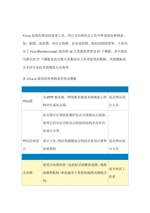
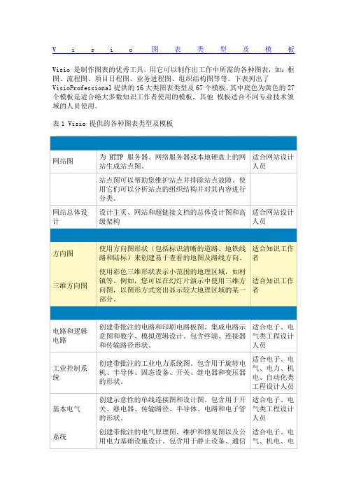
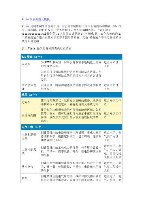
V i s i o图表类型及模板Visio 是制作图表的优秀工具,用它可以制作出工作中所需的各种图表,如:框图、流程图、项目日程图、业务进程图、组织结构图等等。
下表列出了VisioProfessional提供的16大类图表类型及67个模板,其中底色为黄色的27个模板是适合绝大多数知识工作者使用的模板,其他模板适合不同专业技术领域的人员使用。
表1 Visio 提供的各种图表类型及模板网站图为 HTTP 服务器、网络服务器或本地硬盘上的网站生成站点图。
适合网站设计人员站点图可以帮助您维护站点并排除站点故障。
使用它们可以分析站点的组织结构并对其内容进行分类。
网站总体设计设计主页、网站和超链接文档的总体设计图和高级架构适合网站设计人员方向图使用方向图形状(包括标识清晰的道路、地铁线路和陆标)来创建易于查看的地图及路线方向。
适合知识工作者三维方向图使用彩色三维形状表示小范围的地理区域,如村镇等。
例如,您可以在幻灯片演示中使用三维方向图,以图形方式突出显示较大地理区域的某一部分。
适合知识工作者电路和逻辑电路创建带批注的电路和印刷电路板图、集成电路示意图和数字、模拟逻辑设计。
包含终端、连接器和传输路径形状。
适合电子、电气类工程设计人员工业控制系统创建带批注的工业电力系统图。
包含用于旋转电机、半导体、固态设备、开关、继电器和变压器的形状。
适合电子、电气、电力、机电、自动化类工程设计人员基本电气创建示意性的单线连接图和设计图。
包含用于开关、继电器、传输路径、半导体、电路和电子管的形状。
适合电子、电气类工程设计人员系统创建带批注的电气原理图、维护和修复图以及公用电力基础设施设计。
包含用于静止设备、通信适合电子、电气、机电、电设备和固态设备的形状。
力类工程设计人员工艺流程图为管线工程系统(工业、制炼、真空、流体、水力和气体)、管线工程支持、材料配送和液体输送系统创建工艺流程图(PFD)。
适合工业、仪表类工程设计人员管道和仪表设备图为管线工程系统(工业、制炼、真空、流体、水力和气体)、管线工程支持、材料配送和液体输送系统创建管道和仪表设备图(P&ID)。
visio analog circuit 模板-回复Visio is a powerful tool that allows engineers and designers to create and visualize electrical and electronic circuit diagrams. With the help of Visio, professionals can easily and accurately represent analog circuits, helping them design, test, and analyze circuit components and systems.Analog circuits are widely used in various applications, including audio amplifiers, signal processing circuits, and control systems. These circuits process continuous signals, which vary in a smooth and continuous manner, unlike digital circuits that process discrete signals. Designing analog circuits requires a deep understanding of electronic components and their behavior in different configurations.To start creating an analog circuit diagram in Visio, follow these step-by-step instructions:Step 1: Launch Visio and open a new documentAfter launching Visio, select "New" from the "File" menu. In the template categories, choose "Circuit and Logic Diagrams" and then select the appropriate analog circuit template. Visio provides avariety of templates for different types of analog circuits, such as op-amp circuits, filter circuits, and oscillator circuits.Step 2: Drag and drop components from the stencil onto the drawing pageVisio provides a stencil library with a wide range of electronic components, including resistors, capacitors, transistors, and operational amplifiers. Drag and drop the required components onto the drawing page, positioning them according to the circuit arrangement. Use the gridlines and alignment tools in Visio to ensure neat and organized placement of the components.Step 3: Connect components using wires and busesUse the connector tool in Visio to draw wires between the component terminals. Visio provides different types of connectors, such as straight lines, curves, and orthogonal lines, allowing you to create well-organized circuit connections. You can also use buses to group related connections, simplifying the circuit diagram.Step 4: Label components and wiresTo make the circuit diagram more informative, add labels to components and wires. Visio enables you to insert text boxes andcaptions, which can be customized with different fonts, sizes, and styles. Labeling components with their values or designations helps in understanding the circuit, while properly annotating wires makes troubleshooting and maintenance easier.Step 5: Customize the appearance of the circuit diagramVisio allows you to customize the appearance of the circuit diagram by changing the line styles, colors, and thicknesses. Use different line styles to distinguish between power supply lines, signal lines, and ground connections. Adding a border and a title block to the diagram enhances its professional look.Step 6: Save and share the circuit diagramOnce the analog circuit diagram is complete, save it in an appropriate format, such as Visio's native .vsd format or other common image formats like JPEG or PNG. This ensures that the diagram can be easily accessed and shared with other team members or clients. Additionally, Visio allows you to export the circuit diagram to other software applications like Microsoft Word or PowerPoint, enhancing its usability in technical reports or presentations.In conclusion, Visio is an excellent tool for creating analog circuit diagrams. By following the above steps, engineers and designers can efficiently represent their circuit designs, aiding in the development of high-quality electronic systems. Visio'suser-friendly interface and extensive library of components make it a preferred choice for professionals in various fields, ensuring accurate and visually appealing circuit diagrams.。
集成电路visio元器件模板
在Visio中,您可以通过搜索并添加各种元器件模板来创建集
成电路的图示。
以下是一些常用的集成电路元器件模板:
1. 逻辑门:可用于创建各种逻辑电路,如与门、或门、非门等。
您可以搜索“逻辑门模板”来查找适合的模板。
2. 时钟和时序元件:用于创建时钟信号和时序电路,如振荡器、计数器等。
搜索“时钟元件模板”或“时序元件模板”来查找适合
的模板。
3. 存储器:用于创建存储和读取数据的元器件,如寄存器、RAM等。
搜索“存储器模板”来查找适合的模板。
4. 运算放大器:用于放大电压信号的元件。
搜索“运算放大器
模板”来查找适合的模板。
5. 传感器:用于检测和测量环境中的物理量。
搜索“传感器模板”来查找适合的模板。
这些只是一些基本的元器件模板示例,您可以根据具体需要在Visio中搜索更多集成电路元器件模板。