VAILLSON800系列温控器安装及使用说明书
- 格式:doc
- 大小:1.03 MB
- 文档页数:2
首先根据设计要求选择正确的温控器。
编号。
安装温控器之前,请确保配电系统故障。
操作恒温器后,将恒温器的带电导线和零线端子连接到
连接配电系统的带电线路和零线,然后将温度控制器的控制输出连接到电流连接热膜的热线并将热膜地板加热线转移到温度控制器上。
连接传感器连接器,然后将温度控制器安装到插入墙壁的胶带中,
用螺栓固定牢固;打开并调整温度控制器。
输入并试运行,检查并确认进入恒温器的电路是否泄漏
电气保护装置。
根据用户手册打开、测试和检查
系统是否正常。
电热膜发出大量波长在8-14微米之间的长红外线。
红外线照射后,能量被吸收并转化为热能,从而提高了受体的温度。
看起来像阳光。
电热膜地板温暖了供暖环境,使人体感觉更好。
远红外光束直接到达人体,平衡人体表面的热量排放。
表面和其他外壳,加热比空气加热快,使环境温度更高
平衡。
电热箔表面的材料发出远红外能量,大约十分钟后就会产生热量
身体和蓄热层达到热态重量,热能通过蓄热层缓慢地传递到空气中。
根据热风轻、冷风重的技术原理,加热后空气逐渐增加,
冷空气由电热膜地板连续加热,使其来回流动,最后形成空气
上下垂直对流效应可促进室温达到控温效果
固体热
更多资料关注民熔电气集团,回复“温控设备”获取更多行业资料。
温控器使用说明工作原理温度传感器就是将热电偶或热电阻传感器被测温度转换成电信号,再将该信号送入变送器的输入网络,该网络包含调零和热电偶补偿等相关电路。
经调零后的信号输入运算放大器进行信号放大,放大的信号一路经V/I转换器计算处理后以4-20mA直流电流输出;另一路经A/D转换器处理后到表头显示。
变送器的线性化电路有两种,均采用反馈方式。
对热电阻传感器,用正反馈方式校正,对热电偶传感器,用多段折线逼近法进行校正。
一体化数字显示温度变送器有两种显示方式。
LCD显示的温度变送器用两线制方式输出,LED显示的温度变送器用三线制方式输出。
特点温度传感器采用硅橡胶或环氧树脂密封结构,因此耐震、耐湿、适合在恶劣的现场环境安装使用。
现场安装在热电偶、热电阻的接线盒内使用,直接输出4-20mA、0-10mA的输出信号。
这样既节约了昂贵的补偿导线费用,又提高了信号远距离传输过程中的抗干扰能力;热电偶传感器具有冷端温度自动补偿功能;温度传感器适用范围广、既可以与热电偶、热电阻形成一体化现场安装结构,也可以作为功能模块安装在检测设备中和仪表盘上使用;智能型温度变送器可通过HART调制解调器与上位机通讯或与手持器和PC机对变送器的型号、分度号、量程进行远程信息管理、组态、变量监测、校准和维护功能;智能型温度变送器可按用户实际需要调整变送器的显示方向,并显示变送器所测的介质温度、传感器值的变化、输出电流和百分比例。
介绍温度传感器是现代工业现场、科研院所温度测控的更新换代产品,是集散系统、数字总线系统的必备产品。
一般由测温探头(热电偶或热电阻传感器)和两线制固体电子单元组成。
采用固体模块形式将测温探头直接安装在接线盒内,从而形成一体化的变送器。
温度传感器一般分为热电阻和热电偶型两种类型。
温度传感器具有结构简单、节省引线、输出信号大、抗干扰能力强、线性好、显示仪表简单、固体模块抗震防潮、有反接保护和限流保护、工作可靠等优点。
温度传感器的输出为统一的4~20mA信号;可与微机系统或其它常规仪表匹配使用。
新款温控器使用说明一、简介:二、外观:三、功能:1.温度测量:温控器配有高灵敏度的温度传感器,能够准确地测量环境温度,并将温度数值显示在液晶屏上。
2.温度显示:温控器的液晶屏上显示当前环境的温度,温度单位可以根据用户的需求进行切换,如摄氏度或华氏度。
3.温度控制:温控器具有温度控制功能,用户可以根据需要设置所需的温度范围,当环境温度超出设定的范围时,温控器将自动控制相应的设备开启或关闭,以保持温度在所设定的范围内。
4.报警功能:温控器配有报警器,当环境温度超出所设定的上下限时,温控器将发出声音或闪烁指示灯的警报,提醒用户进行相应的操作或调整。
四、操作说明:1.开机:将温控器插入电源插座,温控器将自动开启,液晶屏显示当前环境温度。
2.温度设置:按下设置按钮进入温度设置模式,在液晶屏上显示所设定的温度范围,通过上下按钮进行调整,确认设置后按下确认按钮保存设置。
3.温度控制:按下控制按钮进入温度控制模式,设置开启和关闭的温度范围,根据需要进行调整,确认设置后按下确认按钮保存设置。
4.报警设置:按下报警按钮进入报警设置模式,设置报警的上下限温度,根据需要进行调整,确认设置后按下确认按钮保存设置。
5.其他功能:温控器还具有其他常用功能,如温度单位切换、屏幕亮度调节等,通过菜单按钮进入相应的设置界面,按照界面上的指示进行操作即可。
五、注意事项:1.为保证测量的准确性,请将温控器安放在通风良好、无遮挡的位置,避免阳光直射。
2.请勿将温控器暴露在潮湿、高温或过于寒冷的环境中,以免影响其正常运行。
4.请注意温控器的电源供应,确保电源稳定并符合要求,避免电压过高或过低对温控器造成损坏。
六、总结:。
温控设备使用方法说明书一、产品概述本设备是一种用于控制温度的电子设备,适用于各种需要温度控制的场合。
该设备具有精度高、操作简便等特点,可广泛应用于工业生产、实验室等领域。
二、产品特性1. 精确控制:本设备采用高精度的温度传感器和控制芯片,能够实时感知环境温度,并根据设定的参数实现精准控制。
2. 多功能显示:设备面板配备液晶屏幕,能够显示当前温度、设定温度以及操作状态和故障码等信息。
3. 安全可靠:设备具备过温保护功能,在温度超过设定范围时会自动切断电源,确保设备和环境的安全。
4. 高效节能:设备采用先进的节能技术,在达到设定温度后能够自动切换到低功耗模式,保证节能效果。
5. 多种控制模式:本设备支持多种控制模式,可根据实际需求选择恒温、程序、循环等模式。
三、产品使用说明1. 设备安装:将本设备放置在平坦的表面上,确保通风良好,不与其他热源或易燃物接触。
保持周围环境清洁,避免尘埃或异物进入设备内部。
2. 设备连接:将电源线插入交流电源插座,并确保电源电压与设备要求相符。
设备须连接地线以确保安全。
3. 设备开机:将电源开关打开,设备将进入待机状态。
此时,液晶显示屏会显示当前室温。
4. 设备设置:按照设备使用场合的需要,通过屏幕上的按键进行参数设置。
根据具体说明书的内容,选择控制模式、设定温度、运行时间等参数。
5. 设备运行:确认参数设置无误后,按下启动键,设备将开始工作,并根据设定的温度进行自动控制。
6. 设备维护:定期清洁设备表面和内部,避免灰尘和杂质影响设备性能。
如发现设备出现故障,请及时断电并联系维修人员处理。
四、注意事项1. 请勿将设备长时间暴露在高温、潮湿或有腐蚀性气体的环境中,以免损坏设备。
2. 设备应放置在儿童无法触及的地方,以防不慎操作或触碰设备。
3. 设备故障时,请勿擅自拆卸修理,应联系售后服务中心或专业维修人员进行处理。
4. 设备在长时间不使用时,应断开电源并妥善保存,以延长设备寿命。
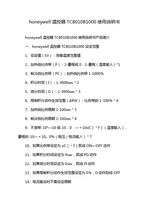
honeywell温控器TC8010B1000使用说明书honeywell温控器TC8010B1000使用说明书产品简介一、honeywell温控器TC8010B1000设定范围1、设定值(SV):同等温度范围值2、加热侧比例带(P):1-量程或0.1-量程(温度输入)*13、制冷侧比例带(PC):加热侧比例带1-1000%4、积分时间(I):1-3600sec*25、微分时间(D):1-3600sec*36、限制积分动作生效范围(ARW):比例带的1-100%*47、加热侧比例周期1-100sec*58、制冷侧比例周期1-100sec*69、不感带-10°—10或-10.0 —+10oC[*F](温度输入),量程的-10—+10。
0%(电压/电流输入)*710、如果比例带设定为oC[﹡F]即成ON—OFF动作11、如果积分时间设定为0sec,即成PD动作12、如果微分时间设定为0sec,即成PI动作13、如果限制积分动作生效范围设定为0%,D动作则成OFF14、电流输出时不需设定周期15、电流输出时不需设定周期16、如果不感带设定为负,则成重叠二、honeywell温控器TC8010B1000控制动作PID控制(ON—OFF.P.PI.PD控制)自动演算功能(AT)1、自调方式:限制周期法2、AT周期3、自主校正设定改变时,自主校正即建立加热/制冷PID控制动作除外,控制输出4、继电器接点输出:250VAC 3A(带负荷)1a连接电气性:超过300000次,额定负荷b)电压脉冲输出:0—12VDC(负荷电阻:超过600Ω)5、·电流输出:4-20maDC(负荷电阻:超过600Ω)6、闸流控制管驱动用触发器输出:零测法中容量驱动7、闸流控制管输出:额定0.5A(环境温度低于40℃)温度报警三、honeywell温控器TC8010B1000报警点:双报警(分别设定)报警种类:偏差报警(上限,下限,上下限,范围内)过程值输入报警(上限,下限)设定值输入报警(上限,下限)可以选择待机机能(设定值报警除外)控制环断线报警(LBA)LBA设定时间:0.1—200.0min不能设定为0.0minLBA不感带:0—9999oC[﹡F](温度输入)0—量程(电压/电流输入)如果设定为0,LBA不动作。
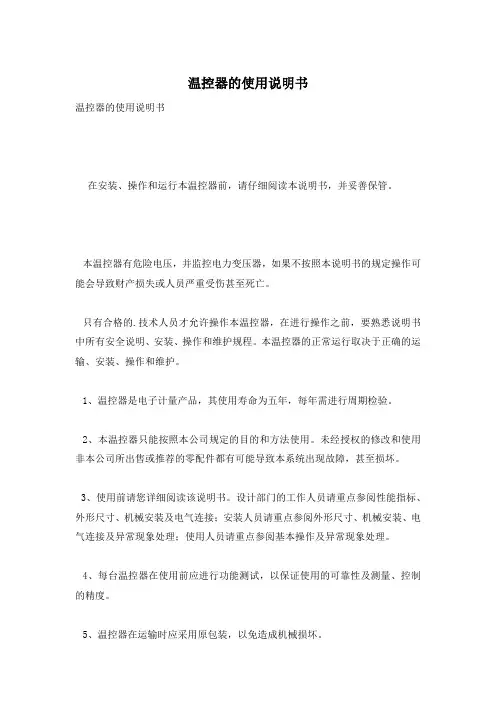
温控器的使用说明书温控器的使用说明书在安装、操作和运行本温控器前,请仔细阅读本说明书,并妥善保管。
本温控器有危险电压,并监控电力变压器,如果不按照本说明书的规定操作可能会导致财产损失或人员严重受伤甚至死亡。
只有合格的.技术人员才允许操作本温控器,在进行操作之前,要熟悉说明书中所有安全说明、安装、操作和维护规程。
本温控器的正常运行取决于正确的运输、安装、操作和维护。
1、温控器是电子计量产品,其使用寿命为五年,每年需进行周期检验。
2、本温控器只能按照本公司规定的目的和方法使用。
未经授权的修改和使用非本公司所出售或推荐的零配件都有可能导致本系统出现故障,甚至损坏。
3、使用前请您详细阅读该说明书。
设计部门的工作人员请重点参阅性能指标、外形尺寸、机械安装及电气连接;安装人员请重点参阅外形尺寸、机械安装、电气连接及异常现象处理;使用人员请重点参阅基本操作及异常现象处理。
4、每台温控器在使用前应进行功能测试,以保证使用的可靠性及测量、控制的精度。
5、温控器在运输时应采用原包装,以免造成机械损坏。
6、温控器不使用时,请进行防潮处理。
7、温控器使用时应注意电源等级(无特殊说明时,一般为AC220V)。
8、当您准备使用温控器时,请仔细阅读该说明书的电气连接部分,确认连接无误后再给温控器送电!9、为保证温控器输入信号质量,温控器正常运行前务必拧紧传感器插头。
10、在干式变压器进行耐压测试前,必须将传感器插头与温控器分离,以避免温控器被损坏。
11、切勿用打火机等明火对传感器探头进行模拟温升试验,否则会损坏Pt100传感器。
12、避免在含有二氧化硫(SO2)或其他腐蚀性气体的环境中使用本温控器,否则会使继电器的触点失效。
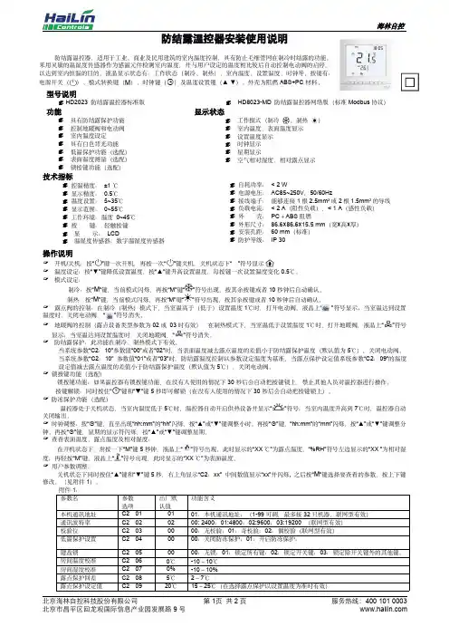
防结露温控器安装使用说明防结露温控器,适用于工业、商业及民用建筑的室内温度控制,具有防止毛细管网在制冷时结露的功能。
采用灵敏的温湿度传感器作为感温元件检测室内温度,并与用户设定的温度相比较后自动控制电动阀的启停,以达到室内恒温的目的。
液晶显示状态有:工作状态(制冷、制热)、室内温度、设置温度、时钟等。
按键有:电源开关()、模式转换键()、时钟键( )及温度设置键(▲▼)。
外壳为阻燃ABS+PC 材料。
型号说明 HD2023防结露温控器标准版HD8023-MD 防结露温控器网络版(标准Modbus 协议)功能显示状态具有防结露保护功能 控制地暖阀和电动阀 室内温度设定 具有白色背光功能 低温保护功能(选配) 表面温度测量(选配) 锁按键功能(选配)工作模式(制冷、制热) 室内温度、表面温度显示 设置温度显示 时钟显示 星期显示空气相对湿度、相对露点显示技术指标控温精度:±1℃ 显示精度:0.5℃ 温度设置:5~35℃ 显示范围:0~55℃ 工作环境:温度0~45℃ 按键:轻触按键 显示:LCD温湿度传感器:数字温湿度传感器自耗功率:<2W电源电压:AC85~250V ,50/60Hz接线端子:能够连接1根2.5mm 2或2根1.5mm 2的导线 负载电流:<2A (阻性负载),<1A (感性负载) 外壳:PC +ABS 阻燃外形尺寸:86.6×86.6×15.5mm (宽×高×厚) 安装孔距:60mm (标准)防护等级:IP 30操作说明✍开机/关机:按“”键一次开机,再按一次“”键关机,关机状态下“”符号显示。
✍温度设定:按“▼”键降低设置温度,按“▲”键升高设置温度,每按键一次设置温度变化0.5℃。
✍模式设定:制冷:按“”键,当前模式闪烁,再按“M”键“”符号出现,按其余按键或者10秒钟后自动确认。
制热:按“”键,当前模式闪烁,再按“M”键“”符号出现,按其余按键或者10秒钟后自动确认。
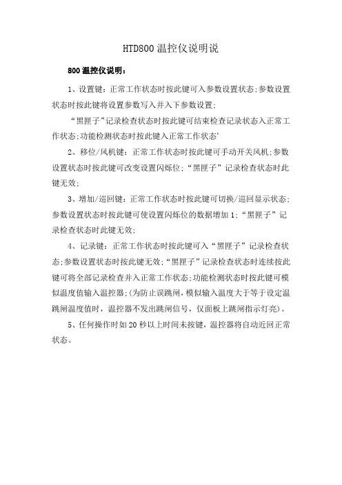
HTD800温控仪说明说
800温控仪说明:
1、设置键:正常工作状态时按此键可入参数设置状态;参数设置状态时按此键将设置参数写入并入下参数设置;
“黑匣子”记录检查状态时按此键可结束检查记录状态入正常工作状态;功能检测状态时按此键入正常工作状态'
2、移位/风机键:正常工作状态时按此键可手动开关风机;参数设置状态时按此键可改变设置闪烁位;“黑匣子”记录检查状态时此键无效;
3、增加/巡回键:正常工作状态时按此键可切换/巡回显示状态;参数设置状态时按此键可使设置闪烁位的数据增加1;“黑匣子”记录检查状态时此键无效;
4、记录键:正常工作状态时按此键可入“黑匣子”记录检查状态;参数设置状态时按此键无效;“黑匣子”记录检查状态时连续按此键可将全部记录检查并入正常工作状态;功能检测状态时按此键可模似温度值输入温控器;(为防止误跳闸,模似输入温度大于等于设定温跳闸温度值时,温控器不发出跳闸信号,仅面板上跳闸指示灯亮)。
5、任何操作时如20秒以上时间未按键,温控器将自动近回正常状态。
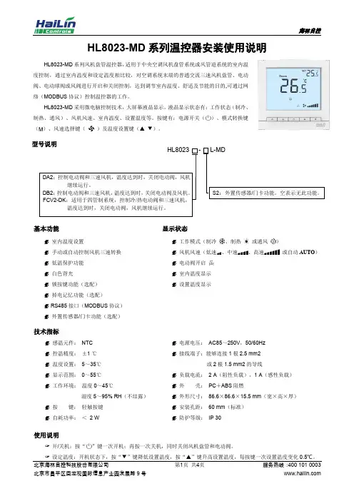
HL8023-MD 系列温控器安装使用说明HL8023-MD 系列风机盘管温控器,适用于中央空调风机盘管系统或风管道系统的室内温度控制,通过室内温度和设定温度相比较,对空调系统末端的普通交流三速风机盘管、电动阀、电动球阀或风阀进行开启和关闭控制,达到调节室内温度、舒适及节能的目的,可通过网络(MODBUS 协议)控制温控器的工作。
HL8023-MD 采用微电脑控制技术,大屏幕液晶显示,液晶显示状态有:工作状态(制冷、制热、通风)、风机风速、室内温度、设置温度等。
按键有:电源开关()、模式转换键()、风速选择键()及温度设置键(▲ ▼)。
基本功能 显示状态室内温度设置手动或自动控制风机三速转换 低温保护功能 白色背光锁按键功能(选配) 掉电记忆功能(选配) RS485接口(MODBUS 协议) 外置传感器/门卡功能(选配)工作模式(制冷、制热或通风)风机风速(低速、中速、高速或自动AUTO )电动阀开启室内温度显示 设置温度显示技术指标感温元件: NTC 控温精度: ±1 ℃ 温度设置: 5~35℃ 显示范围: 0~55℃ 工作环境: 温度0~45℃湿度5~95% RH (不结露)按 键: 轻触按键 自耗功率: < 2 W电源电压: AC85~250V ,50/60Hz 接线端子:能够连接1根2.5 mm2或2根1.5 mm2的导线负载电流: 2 A (阻性负载),1 A (感性负载) 外 壳: PC +ABS 阻燃外形尺寸: 86.6×86.6×15.5 mm (宽×高×厚) 安装孔距: 60 mm (标准) 防护等级: IP 30使用说明✍ 开/关机:按“”键一次开机;再按一次关机,同时关闭风机盘管和电动阀。
✍ 设定温度:开机状态下,按“▼”键降低设置温度,按“▲”键升高设置温度,每按键一次设置温度变化0.5℃。
型号说明HL8023 -L-MDDA2:控制电动阀和三速风机,温度达到时,关闭电动阀,风机继续运行。
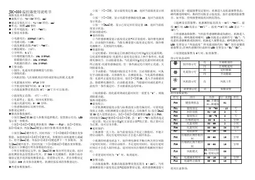
JDC-800温控器使用说明书规格及技术参数说明:◆面板尺寸:78×38(单位:mm)◆建议安装孔尺寸:71×30(单位:mm)◆外壳:阻燃ABS塑料◆工作环境温度:0℃~+60℃;◆主要技术参数:◇电源电压:220VAC±10%;◇电源功耗:≤3W;◇温度测量范围:-40℃~+90℃;◇测量精度:±l℃;◇分辩率:0.1℃;◇压缩机输出接点:10A 240VAC;除霜输出接点:10A 240VAC;风机输出接点:10A 240VAC;◆主要功能:◇制冷、化霜双传感器测量与控制;◇强制化霜;◇风机控制:与压缩机同启同停或持续运转模式选择◇化霜滴水时间:0-15分钟◇开机延时保护时间:0~9分钟◇高低温报警设置范围:O℃~20℃并可以取消;◇温度校正范围:-5℃~+5℃;◇化霜终止,温度、时间双重控制;◇最大化霜时间:0~99分钟;◇传感器故障后比例开停机。
参数设定操作:◆修改参数值操作:◇按住[Set]键3S进入参数项选择模式,设置指示灯亮;LED 显示某一参数项;◇按[︽]或[︾]键选择参数项(F00……F12),按[︽]增加,按[︾]减少,再按[Rst]键显示相应参数项的参数值;◇按住[Set]键不松手,同时再按一下[︽]键或[︾]键改变参数值,如连续按[︽]或[︾]键不放,参数值自动快速增大或减小;松开[Set]键,单按[︽]或[︾]键选择下一个参数项,按住[Set]键不松手,同时再按一下[︽]键或[︾]键改变参数值,重复以上步骤进行所有参数值的设定;◇所有参数设定完毕,按 [Set]键3S保存所有设定值,返回温度测量状态设置指示灯灭。
若30S后无键操作,机器自动存储设定值并返回温度测量状态,设置指示灯灭。
若在参数设定完成后30S内未保存就断电,机器仍按原来的参数值运行。
◆查看参数值操作:◇按一下[︽]键,显示温度设定值2S,返回当前温度显示状态;◇按一下[︾]键,显示化霜传感器温度值2S,返回当前温度显示状态;◇按一下[Rst]键,显示已设定回差设定值2S,返回当前温度显示状态。
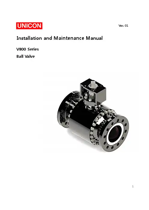
Installation and Maintenance ManualV800SeriesBall ValveVer.011Installation&Maintenance ManualTable of Contents1.Introduction2.Pre-Inspection3.Installation4.Operation5.Maintenance6.Disassembly/Reassembly7.Storage8.Packing9.Transport21-2Personnel qualification Transport,installation,commissioning,maintenance or repair must only be performed by trained or instructed personnel.WarningIn order to ensure successful and safe operation of our valves the entire operation manual must have been read through and understood prior to installation and commissioning.Under certain operating conditions,the use of damaged equipment could cause a degradation of the performance of the system which may lead to personal injury or death.If you have any questions about problems arise,contact UNICON office.Installation &Maintenance ManualTrunnion-Mounted Ball Seat RingSeat InsertSpring1-3Principle of OperationThe main function of the Trunnion Mounted Ball Valve is to cut off or connect the flow of fluid in a pipeline system.Via the manual hand wheel or other driving device,application of torque force allows the ball to rotate 90degrees,enough to align the ball bore to the centerline passage of the ball valve body,thus allowing fluid to pass through it.2.Pre-InspectionBefore installation of valve to the ‘Pipe Line’,it is recommended to inspect a valve closely as below.4Installation&Maintenance Manual2-1.Inspecting Valve&Accessory-Ensure any damage that might be occurred during the transportation.-Remove the protection cover of valve just before installation and clean a dust or harmfulparticles with an air blaster or smooth dust cloth/clean towel.-Check the tightness of all kinds of bolts and nuts.2-2.Inspecting Pipeline-Remove foreign materials such as a rust,welding chip,etc,which remain in the pipe orflange.-Make sure the clearness of pipe flange and gasket surface.Caution:When the fluid is flowing through the line,any foreign material is subject to scratch theseat and inner body,so that the scratch may cause leakage and shortening of the valvelifetime.To avoid product damage,inspect the valve before installation for any damage or anyforeign material that may have collected in the valve body.Also remove any pipe scale,welding slag,or other foreign material from the pipeline.3.InstallationIt is recommended to install valves on horizontal piping in a upright position.3-1Check the following items before valve mounting1.Service conditions should be within the valve specifications.2.Valve flanges should correspond with piping flanges.3.Gasket contact surfaces of pipes and valve flanges must be thoroughly inspected tomake sure no scratch or any other indication of flaw is found.4.The appropriate length should be kept between pipe flanges for the valve face-to-facedimensions including gasket thickness.5.The valve and pipe center should be aligned accurately.6.Bolt holes of flanges should be arranged symmetrically lined up against the center lineof flanges.57.Remove flange covers from valves just before installation.8.Check all stud bolts /nuts after installation and retighten them,if needed.Installation &Maintenance Manual Caution Before installation,the connecting pipes should be cleaned to remove any foreign object such as sand dust and welding spatters from the connecting pipe interior.CautionHandle valves carefully so that they may not fall or drop on the ground.Any extraordinary mechanical impact should be avoided.CautionPiping should be flushed before test operation,with valves open to assure removal of any foreign object that could damage valves.DO not operate valve during flushing.3-2Installation Procedure1.Make sure that pipes should be aligned accurately.2.The length between piping flanges should correspond with the valve face-to-face including gasket thickness.3.Place the valve between pipe flanges.Install two stud bolts at the bottom of the flanges lightly.4.Insert gaskets between valve and pipe flanges.5.Make sure the correct alignment of gaskets which are placed on bottom flange bolts between valve and pipe flanges.Figure 1.Installation6Installation&Maintenance Manual6.Stud bolts through the other bolt holes and tighten them lightly.7.Tighten bolts evenly,gradually and alternately in a star pattern as shown below.(See.Fig.2)The ends of all tightened bolts should protrude equally beyond the nuts.8.Raise the line temperature and pressure gradually on test operation Retighten the studbolts/nuts,if needed.Figure2.Flange Bolt Tightening SequenceWarningPersonal injury or system damage may result if the ball valve is installed where service conditions could exceed the limits given in the Specifications.Additionally,physical damage to the ball valve may result in personal injury or property damage due to escaping of accumulated fluid.To avoid such injury and damage,install the ball valve in a safe location.4.OperationThe valve is only intended to block or allow flow through the pipeline.The valve should only be used in either fully open or fully closed position.Do not use this valve to regulate flow by partially opening or partially closing the valve.The valve should not stay in a semi-open or semi-closed state for more than two minutes.Do not use the ball valve in process conditions where the pressure,temperature,media and other technical conditions exceeds the limitations set by the valve’s specification.WarningTo avoid possible personal injury,equipment damage,or leakage due to fluid,make certain the ball valve is installed as instructed in the Installation.7Installation &Maintenance ManualCaution 1.Wear the protective items such as goggle,gloves and working shoes.2.Take safely measures against the toxic,flammable or corrosive fluid.3.Reduce the line pressure to the atmospheric level before retightening packing gland and flange bolts and nuts.4.Operators should take protective measures to prevent direct exposure to the fluid.when the fluid spouts out from flange areas.5.Reduce theline pressuretotheatmosphericlevel,whenthe packing and gaskets arereplaced or bolts and nuts are loosened.Operator should take protective measures toprevent direct exposure to the fluid when the fluid spouts out from valves.6.Do not apply the lubricant to the pipes and valves which handle oxygen.Caution If the ball valve is equipped with test connection port,make sure that it is fully closedbefore pressurizing the valve.1.Check that proper installation is completed and any downstream equipment has beenproperly adjusted.2.Ensure that the pipeline system is free of foreign material before the startup.3.Make sure that the ball valve is fully turned to the open position before allowing fluidto pass through the valve.5.MaintenanceWarning Personal injury,equipment damage,or leakage due to escaping fluid may result if seals are not properly lubricated or maintained.Due to normal part wear or damage that may occur from external sources,ball valve should be inspected and maintained periodically.The frequency of inspection,maintenance,and replacement of parts depend upon the severity of service conditions or the requirements of local,state,and federal regulations.Ball valves that have been disassembled for repair must be tested for proper operationbefore returning it to service.In the maintenance process,take appropriate protective measures,such as wearing protective clothing,oxygenmasks,and gloves.Discharge the residual materials inside thevalve body before doing repair or maintenance.For electric,hydraulic or pneumatic valves,ensure that these lines are shut off before performing maintenance.8Installation &Maintenance ManualTrouble ShootingTrouble Possible Causes Remedial MeasureDisturbed valve operation Foreign objects mayhavechoked up the valve body cavity and stuck around the ball seat.Disassembleand inspect thevalve components.Excessive valve torque Foreign objects may have stuck to the stem.Remove the foreign object andcheck the valve Foreign objects may have choked up the valve body cavity and stuck around the ball seat.Flushthe valve bore with thefluid withthe valve slightly open to remove the built-upobjects or disassemble andinspect the valve The gland bolts may have been overly tightened.Once loosen thegland boltsand adequatelyretighten themto an extent that the leakage does not occur.Leakage from the packing box area Loose gland bolts.Retighten the gland bolts.Uneven tightening of the gland bolts.Onceloose the bolts andevenly retighten them.Damage on the packing part.Replace the packing part.Internal through-bone leakage Damage on the ball seats.Disassemble and inspect the valve Replace ball seats.Abnormal noise or vibration Loose bolts and nuts.Retighten the bolts and nuts.-Check the tightness of all nuts/bolts.-Regularly check if theball valve is set at the desired position whether fully open or fullyclosed.If the ball valve cannot be switched to either fully open or fully closed position,valve service is required.-Ensure the electrical continuity of the valve.(if needed)-Ensure that no leakage is being observed from the valve.-Frequent observation is recommended under extreme service condition.-It is advisable to maintain a record of the performance of the valve.-Mounting studs/nuts of the worm gearbox may be checked for tightness and retightened if necessary.-Do not use the valve as a ladder or pedestal when reaching equipment located above the valve.Do not hang additional weight to other related accessory of the valve.9Installation &Maintenance ManualFrequency of maintenance“Maintenance”means totally manage performance and function of valves and prevent from various damages.Frequency of maintenance depends on the below conditions.1.Shape of valve 2.Service temperature,class and materials used 3.External effects 4.Frequency of operate 5.Purpose of use 6.Maintenance methodsPart PurposeMethod ActionBody To Prevent for external leakage,seat leakage and wrong operation.Check the surface of seat and gasket for damages with the naked eyes.Overhaul REMARK :Repair by Lapping when the damage is small.If the damage of surface of seating and erosion are big,reprocess or replace it.Seat &Ball To Prevent for seat leakage and operation error.Check the surface of seat for damages with the naked eyes.Overhaul REMARK :Repair by Lapping when the damage is small.If the damage of surface of seating and erosion are big,reprocess or replace it.Stem To Prevent for external leakage and operation error. 1.Check scratches and seizing.2.Check the Gland packing-contact of stem for damage.Overhaul REMARK :If packing-contact of stem have damage or flexure or twisting,replace it.Bonnet Bolting To Prevent for loosing and separation of bolting and external leakage.Check the valve torque and tighten up bonnet bolting again if needed.Packing 1.To Prevent for operation error.2.To Prevent for external leakage by damage of stem.1.Check dry condition and cleanliness for threaded part of stem.2.If packing have damage,replace it.GasketTo Prevent for external leakage..Check loosing of bonnet bolting and tighten up it again if needed.REMARK :When valves are supplied to the client,it is optimal conditions that is satisfied with design requirements after inspection and test.But tightening of bolts can be affected by installation or test-run conditions.For the long operation,client definitely needs inspection as above to operate without leakage.Maintenance methods of valve10Installation&Maintenance Manual6.Disassembly/ReassemblyWarningTo avoid personal injury resulting from sudden release of pressure,isolate the ball valve from all pressure and cautiously release trapped pressure inside the valve chamber before attempting disassembly.Ensure that the middle chamber of the valve is fully depressurized before dismantling ormaintaining the valve.Pressure inside the pipe may be released,but the middle chambermay still have residual pressure.Open and close the valve several times to ensure that the pressure in the valve is completely released.If the media conveyed by the valve is toxic,inflammable,or explosive,make sure that there are no residual media left in the valveespecially in the middle chamber.Flush the valve with water or the appropriate cleaningsolvent to ensure the complete removal of the residual media.Open and close the valveseveral times while flushing the valve.Observe proper protective measures when dismantling the valve.If the media conveyed by the valve is toxic,inflammable,or explosive,always wear personal protective equipment to avoid any injury or accident.Keep the working site away from fire,sparks,or ignitionespecially if the media is combustible.To disassemble the valve,start disassembling with the last part as outlined in the assembly section.Place the dismantled parts on a soft mat.Do not allow it to have direct contactwith the ground.Mark the dismantled parts correctly to avoid confusion during the assembly.Do not dropor apply excessive force to the valve and its related parts to avoid damage or deformation of the components.if it will not be used for a long time,store the dismantled parts in asafe and dry area in order to protect it and prevent the formation of rust.6-1.Separation of Valve from the Pipe LineTo repair leaking valve,the valve must be removed from pipe line and then parts must be separated as below-Before removing the valve from the line,make sure that the line has been fully depressurized.-Drain all mediums from the pipe.-Remove the parts and remove the valve from the pipe.-Once the valve is removed,appropriate isolation of the pipe ends should be undertaken by the operator/contractor to prevent the creation of a combustible mixture where possible,and to prevent the introduction of dirt and debris into the system.-Mark the location of each part of valve and pipe in order to be installed at same places where they were.11Installation &Maintenance Manual6-2.Disassembly (See.Fig.4)-Unfasten the yoke bolt and then remove operator from body.-Refer to the appropriate operator instruction manual for actuator removal and replacement procedures.-Valve shall be positioned vertically by resting body side flanges on clean ground surface (preferably covered with rubber sheet).Ensuring no damage to the bottom /end face /threads as applicable.-Rotate the ball to fully open position.-Open the side flange joint by loosening the nuts in sequence.(See.Fig.2)Always tighten /loosen the bolts in flange bolt sequence.-Remove side flange,side flange gasket from body.-Remove O-ring or graphite(fire safety),spring,spring back-up ring from body.-Remove packing,packing box and packing flange by loosening bolt.-Remove bottom flange by loosening bolt.-Remove stem,ball,guide bush from body &side flange.-All the components should be stored in a clean place.Figure 3.Separation of Valve (RTJ Flange Type)FlangeMetal Ring Joint GasketValveMetal Ring Joint GasketFlange12Installation &Maintenance Manual6-3.Reassembly (See.Fig.4)-Body shall be positioned vertically by resting body side flanges on clean ground surface.(preferably covered with rubber sheet).-Apply suitable anti-seize grease to bolts.Warning Failure to properly follow the Assembly Instructions could result in ball valve damage,personal injury,and property.-Before reassembly,inspect the valve for any damage on side flange &all internals.-Ensure the cleanness of valve.-Damaged internals to be replaced by genuine &with recommended parts only.-New set of O-rings and gaskets shall be used once the valve is dismantled.-Assembly works in reverse order of disassembly.13Warning Failure to properly follow the Assembly Instructions could result in ball valve damage,personal injury,and property damage due to escaping process fluid during testing or after installing the ball valves in the pipe line.Before the performing the assembly work,clean all components of the ball valve and the working area.Ensure that there are no iron fi lings,rust,welding slag,and other debris inside the valve.keep all valve parts and the working area clean all throughout the assembly process.The working area must be padded with any soft material or mat.Do not allow the valve body,its components,or any of its assembled parts to have direct contact with the ground.Be careful with the lifting and moving of the ball valve’s components.Excessive force applied to the assembly may damage or deform the valve,its related parts,and its components which may cause the ball valve to malfunction.Installation &Maintenance ManualFigure 4.Ball Valve Assembly DrawingWrench boltWrench boltPacking BoxGasketPacking SetStem GuideStemGuide BushBearingBallSeat RingSpringSpring Back-up RingGasketStud &NutSide FlangeGasket Bottom FlangeStud &NutPacking FlangeO-ring or Graphite14Installation &Maintenance Manual7.StorageDuring storage,protect the valves from external effects and dirt.Avoid the formation of condensate through ventilation,desiccant or heating.Protect the connection openings to prevent entry of dirt or foreign matter.The storage room should be dry,dust-free and moderately ventilated.Storage temperature frost-free up to +25℃.8.PackingWarningValves that have come in contact with health-threatening media at the customer must be decontaminated prior to packaging.Valves that can be no longer be moved by hand must be transported with lifting equipment suitable for the weight to be moved.Transport the valves by using Eyebolts if available.Do not hook up lifting equipment to accessories such as hand wheels,control lines,pressure gages or flange bores.When using suspension belts,these must be placed around the valve body,providing edge protection and ensuring even weight distribution.Pack the valves so that any coatings or accessories such as plug-in devices,controllers and sensors cannot be damaged through subsequent transport.Protect connection openings to prevent the entry of e the packing material in accordance with the applicable regulations and observe country specific regulations.9.Transport15。
NO: TC-076M PRODUCT: E5EC-800, E5AC-800 Controllers DATE: October 2014 TYPE: Modification Notice
E5EC-800 and E5AC-800 Temperature Controllers Manual Modified with Valve Opening Monitor Instruction Effective Date: January 2015 production Reason for Modification: To show the location of the Valve Opening Monitor setting in the setup sequence.
Affected Parts Models Specification Models Specification E5EC-RX2ASM-800 AC 100-240V E5AC-RX1ASM-800 AC 100-240V E5EC-RX2DSM-800 AC/DC 24V E5AC-RX1DSM-800 AC/DC 24V E5EC-QX2ASM-800 AC 100-240V E5AC-QX1ASM-800 AC 100-240V E5EC-QX2DSM-800 AC/DC 24V E5AC-QX1DSM-800 AC/DC 24V E5EC-RR2ASM-800 AC 100-240V E5AC-RX3ASM-800 AC 100-240V E5EC-RR2DSM-800 AC/DC 24V E5AC-RX3DSM-800 AC/DC 24V E5EC-QR2ASM-800 AC 100-240V E5AC-QX3ASM-800 AC 100-240V E5EC-QR2DSM-800 AC/DC 24V E5AC-QX3DSM-800 AC/DC 24V E5EC-CX2ASM-800 AC 100-240V E5AC-CX1ASM-800 AC 100-240V E5EC-CX2DSM-800 AC/DC 24V E5AC-CX1DSM-800 AC/DC 24V E5EC-CR2ASM-800 AC 100-240V E5AC-CX3ASM-800 AC 100-240V E5EC-CR2DSM-800 AC/DC 24V E5AC-CX3DSM-800 AC/DC 24V E5EC-RR2ASM-808 AC 100-240V E5AC-RX3ASM-808 AC 100-240V E5EC-QR2ASM-808 AC 100-240V E5AC-QX3ASM-808 AC 100-240V E5EC-CR2ASM-804 AC 100-240V E5AC-CX3ASM-804 AC 100-240V E5EC-RR2DSM-808 AC/DC 24V E5AC-RX3DSM-808 AC/DC 24V E5EC-QR2DSM-808 AC/DC 24V E5AC-QX3DSM-808 AC/DC 24V E5EC-CR2DSM-804 AC/DC 24V E5AC-CX3DSM-804 AC/DC 24V E5EC-RR2ASM-810 AC 100-240V E5AC-RX3ASM-810 AC 100-240V E5EC-QR2ASM-810 AC 100-240V E5AC-QX3ASM-810 AC 100-240V E5EC-RR2DSM-810 AC/DC 24V E5AC-RX3DSM-810 AC/DC 24V E5EC-QR2DSM-810 AC/DC 24V E5AC-QX3DSM-810 AC/DC 24V
智享800太阳能热水器使用说明书
一.主要技术指标:
1.使用电源:220VAC 功耗:
2.测温精度:士2℃
3.测温范围:0-99℃
4.控温精度:士2℃
5.水位分档:五档环形显示
6.可控水泵或电热带功率:<500W
7.可控电加热功率:<1500W可选:3000W
8.漏电动作电流:<10mA/
9.电磁阀参数:直流DC12V,可选用有压阀或无压阀无压阀工作压力:,适用于水箱供水或低压供水
10.广域亮彩显示屏低功耗: 【主要功能】
1.北京时间:实时显示北京时间
2.水位预置:可预置加水水位 50、80、100%
3.水温预置:可预置加热温度范围:30℃-80℃,定时加热若不需要启动电加热
使用说明:
1、打开进水阀和水龙头,插上电源,按下热水器的开关按钮;
2、设置水温;
3、水烧开后先把阀门调至中间位置,试下水温合适即可使用;
4、使用完毕后,先关闭电热水器上的开关,等手擦干之后,再拔掉电源。
二.注意事项:
1、不要将仪表安装在能被水冲淋到的地方。
2、遇到雷雨天气时,请关闭电源并拔下水温水位传感器插
头,否则容易造成仪表的损坏。
3、为保护太阳能热水器及水温水位传感器,水箱内不得长期无水。
4、在安装和维护过程中,不得将硅胶帮传感器弯折,否则会造成传感器的损坏。
温度控制器使用说明书一、产品概述温度控制器是一种用于控制和调节温度的设备。
它可以实时监测环境温度,并按照预设的温度范围进行自动控制,以确保温度保持在设定值内。
二、产品组成1.主机:包含显示屏、按键和控制电路等组件,用于设置和监控温度控制器的工作状态。
2.传感器:用于感知环境温度的变化,并将其转化为电信号,传输给主机进行处理。
3.输出端口:用于连接外部设备,如加热器、冷却器等,以实现温度调节。
三、使用步骤1.连接电源:将温度控制器插入电源插座,并确保电源稳定。
2.连接传感器:将传感器插入温度控制器的传感器接口中,并确保连接牢固。
3.设置温度范围:按照产品说明书中的指引,通过按键设置所需的温度范围。
4.连接外部设备:根据需要,使用合适的电缆将外部设备连接至温度控制器的输出端口上。
5.开机:按下电源按钮,温度控制器将开始运行,并在显示屏上显示当前温度及工作状态。
6.调试和调节:根据实际需要,适时调整温度控制器的参数,以达到预期的温度控制效果。
四、注意事项1.请确保温度控制器在通风良好的环境中工作,避免遮挡或靠近高温的物体。
2.避免温度控制器长时间暴露在潮湿、尘土等有害环境中,以免影响正常使用寿命。
3.使用前请认真阅读产品说明书,并按照要求正确操作,以免因误操作导致设备损坏或操作失误。
4.在设置温度范围时,请合理选择上下限,避免因温度波动过大造成设备故障或无法达到所需温度。
5.如遇到温度控制器异常工作或其他问题,请及时联系售后服务中心进行咨询或维修。
五、常见问题解答1.温度控制器显示屏无法正常工作怎么办?答:请检查电源接口是否接触良好,确认电源供电充足,并检查是否有异常开关或损坏的部件。
2.温度控制器无法控制温度在设定范围内怎么办?答:请确认传感器连接是否正确,温度控制器和外部设备的连接是否稳固,并适时调整温度范围和控制参数。
3.温度控制器显示温度与实际温度不一致怎么办?答:请检查传感器的位置是否合理,避免受到外部干扰,如阳光直射或其他热源等。
操作说明书1.“舒适模式”和“日/周计划”模式温控器正常工作时处于预定的日计划或周计划模式下,按照预设的时间段工作。
如果某个预设时段的目标温度设为“oF”,则该时段停止加热,且屏幕关闭。
当温控器运行在日/周计划时,按【】键可以临时关闭加热,此时屏幕熄灭,直至下一个目标温度不为“oF”的时段来临,温控器会自动开启。
在屏幕熄灭状态下,按【】键可临时启动“舒适模式”,温控器按照舒适模式预设的目标温度运行,4小时后自动返回日/周计划模式。
自动返回的时间可在后台管理界面中设定,范围1~99小时。
2.解除锁定:温控器默认处于锁定状态(显示“”图标),在对温控器进行除设定时间以外的操作时,将提示输入4位密码。
按【】【】键调节当前位的密码(0~F),按【】切换到下一位,按【】键确定。
密码正确后,温控器解除锁定(“”图标消失),否则将返回并保持锁定状态。
解除锁定后,无按键操作30秒后会自动重新锁定,也可长按【】键手工锁定。
3.切换工作模式:在解锁后,按【】键可在“舒适”“日计划”“周计划”三种模式之间切换,按【】确定。
当温控器被切换到“舒适”模式时,将一直以预设的舒适温度运行,无法停止。
可按【】【】键调节舒适模式的目标温度,按【】确定。
当温控器切换到“日计划”或“周计划”时,可按【】键调节日计划或周计划的时段和温度,详见下节。
4.日计划时段和温度设置在已解锁且处于日计划模式下(即使屏幕熄灭也可设置),按【】键可调节日计划设置。
首先是时间栏显示00:00,设定温度闪烁,可按【】【】键调整从00:00开始的目标温度,目标温度设为oF 表示该时段关闭加热。
调整温度后按【】键,时间栏闪烁,可设定下一时段的起始时间;再按【】键,设定温度闪烁,可设定该时段的目标温度。
如上循环,直至将时段起始时间设为24:00,表示全天时段设定完成。
按【】键保存设定并返回。
5.周计划时段和温度设置在已解锁且处于周计划模式下(即使屏幕熄灭也可设置),按【】键可调节周计划设置。
VER1.0iDIN800干式变压器温控仪使用说明书广州智光自动化有限公司尊敬的用户,感谢您使用广州智光自动化有限公司的iDIN800干式变压器温控仪,为保证安全、正确、高效地使用本装置,请您详细阅读本说明书!!警告:☞ 注意需保证温度传感器探头及导线的安装时,与变压器的一次高压部分保留足够的电气绝缘距离,以免出现人员安全事故及设备损坏!☞ 在进行变压器耐压实验前,应先将传感器电缆插头与温控仪分离,以免损坏温控仪!!注意☞ 装置外壳要可靠接地。
☞ 禁止用明火烧烤测温探头,这样会损坏传感器或者降低传感器的使用寿命,若需要检测温控仪的输出功能,请使用温控仪的输出模拟检测功能。
☞ 外部接线时,请参照说明书中的电气接线图,注意接线端子是有源还是无源,并参考本说明书对继电器接点容量的说明。
☞ 若本说明书与装置有不对应的,请以装置为准。
目录1概述 (1)2装置特点 (1)3功能介绍 (1)3.1巡回和最高显示 (1)3.2监控功能 (2)3.3手动控制风机功能 (2)3.4风机定时检测功能 (2)3.5模拟输出控制功能 (2)3.6“黑匣子”功能 (3)3.7保护功能配置 (3)3.8通讯功能 (3)3.9模拟量输出功能 (3)3.10参数及定值设置功能 (3)4技术指标 (4)4.1测量范围 (4)4.2测量精度 (4)4.3使用条件 (4)4.4数字补偿范围 (4)4.5继电器触点输出 (4)4.6温控仪功耗 (4)4.7传感器 (4)4.8模拟量输出 (4)4.9通讯 (4)4.10执行标准 (5)4.11抗干扰性能满足JB/T7631《变压器用电阻温度计》标准要求 (5)4.12绝缘性能 (5)4.13防护等级 (5)4.14高温、低温和连续冲击要求 (5)5功能及型号分类 (6)6面板及后盖板外接线图 (6)6.1仪表面板 (6)6.2仪表后盖接线图 (6)7工作状态及按键功能 (7)7.1温控仪工作显示状态 (7)7.2按键功能 (8)8操作说明 (9)8.1温度参数设定 (9)8.2定时启动风机参数设定 (9)8.3通讯参数设定(可选) (10)8.4输出状态检测功能 (10)8.5“黑匣子”功能 (11)8.6厂家功能 (11)8.7用户数字补偿功能设置 (11)8.8装置信息 (12)9装置硬件原理 (12)10iDIN800-01C型通讯功能 (13)10.1功能特点 (13)10.2连接方法 (13)11iDIN800-01D型模拟量输出功能 (14)11.1功能特点 (14)11.24~20mA输出(DB9)插座引脚定义 (14)11.3电流输出技术标准 (14)12现场故障处理小常识 (15)13传感器总成 (16)14接线端子定义 (16)15安装 (17)1概述iDIN800系列智能型温控仪是专门为干式变压器安全可靠运行设计的一种多功能智能温度控制器。
npc800温度模块说明书
请问您需要关于npc800温度模块的什么具体内容的说明书呢?温度模块一般包含以下内容:
1. 产品概述:介绍npc800温度模块的基本特点、功能和适用
范围。
2. 技术参数:列出温度模块的主要技术参数,如测量范围、分辨率、精度、响应时间等。
3. 产品安装:说明温度模块的安装方式和步骤,包括连接电源、接线等。
4. 使用说明:详细介绍如何使用npc800温度模块进行温度测量,包括设置参数、测量方法等。
5. 故障排除:列举常见的故障现象和解决方法,帮助用户尽快解决问题。
6. 注意事项:提醒用户在使用npc800温度模块时需要注意的
事项,如使用环境、防护措施等。
7. 其他附加信息:根据产品实际情况,可能还需要包含一些其他附加信息,如维护保养、售后服务等。
请具体说明您需要哪方面的说明书,我将为您提供详细的说明。
TL-818H温控器安装及使用说明书
TL-818H系列温控器使用说明,用于分室温控和分户温控地暖系统,通过感应房间温度和设定温度的对比,来控制地暖系统的运行状态。
提高舒适度的同时,达到节能的目的。该系列温控器具有手动功能、可编程功能、状态记忆功能 双温双控功能。
显示状态 按键说明:
★ 工作模式: 手动功能标志 ,:时段编程控制 K1 开机或关机
★ 加热运行标志 K2 模式键,手动模式与编程模式切换
★ 显示室内温度 K3 短按设置时钟和星期,长按进入编程设置
★ 显示设置温度 K4 ▲ 向上键
K5 ▼ 向下键
技术规格
温度传感器 :NTC热敏电阻 电源电压:AC180~260V,50/60Hz
控制精度 :±1℃ 自耗功率:< 1W
温度设置 :5~35℃ 负载功率:< 2800W
显示范围 :0~71℃ 接线端子:能够连接2*1.5mm² 或1*2.5mm² 的导线
工作环境 :0~45℃ 外壳:PC+ABS阻燃
显示 :LCD 外形尺寸:86*86*13mm(宽*高*厚)
湿度 :5~95%RH(不结露) 安装孔距:60mm(标准)
操作说明
开关机
按“”键一次开机,再按一次关机。
温度设定 开机状态下,按“▼”键降低设置温度 ,按“▲”键升高设置温度,每按键一次温度变化1℃ 。
模式选择 开机状态下,按“”模式键 ,进行手动模式与编程模式切换。
显示地板温 度 当高级选项中传感器类型选择“AL”时,长按"▲"键, 显示地板温度,三秒后恢复之前显示(选配:双传感器配置时才有此项)
:时段编程控制
周编程循环,每天设置6个时段及每个时段相对应的温度,温控器根据编程运行; 编程功能按键切换
: 早上起床,第一时段 : 早上出门,第二时段 : 中午回家,第三时段
: 中午外出,第四时段 : 晚上回家,第五阶段 : 晚上睡觉,第六时段
长按“”键2秒进入一周编程模式。(见下附表)
调整顺序:周1~周5第一时段定时时间调节→周1~周5第一时段定时温度调节→…→周六周日第六时段时间调节→周六周日第六时
段定时温度调节. 每个参数设置好后按“”键切换各个选项和确认设置值
“▲”设定温度升温键或调节参数值 “▼”设定温度降温键或调节参数值
时段显示
工作日(周一至周五) 休息日(周六至周日)
时间 温度 时间 温度
6:00起床 20℃ 6:00起床 18℃
8:00工作 18℃ 8:00工作 20℃
11:30午休 15℃ 11:30午休 20℃
12:30工作 18℃ 12:30工作 20℃
16:30下班 20℃ 16:30下班 20℃
22:00休息 15℃ 22:00休息 15℃
高级选项设置:
在关机状态下按住“”键5秒以上,进入高级参数设定模式,可对温度进行校正及传感器选择、启动温差、低温保
护、过热保护、锁定选项、休息日选择进行设定,进入模式后可按“”切换各个选项。调整完开机自动确认
显示符号 选项内容 按"▲" 或 "▼"键进行调整
1 温度补偿 -9℃~+9℃
2 启动温差
1℃~5℃,当设定温度大于或等于室内温度加启动温差时,制热设备开启;当室内温度大于或等于
设定温度加启动温差时,制热设备关闭
3 传感器类型
IN:内置传感器(内传感器控温限温) OU:外置传感器(外传感器控温限温) AL:内外置传感器
(内控温,外限温)
4 低温保护设置
5℃~10℃,在最高设置温度10度时再按"▲"键,显示“- -”取消低温保护功能;如果室内温度低
于设定的低温保护温度,加热设备将被强制开启
5 过热保护设置
35℃~70℃,在最低设置温度35度时再按"▼"键,显示“- -”取消高温保护功能;如果室内温度
高于设定的高温保护温度,加热设备将被强制切断
6 按键锁定选项
0: 锁定状态下,按键锁定除开关机键
1:锁定状态下,所有按键锁定包括开关键
7 休息日选择 --无休:1234567 01单休:123456与7 02双休:12345与67
8 保留
9 地址码 01-FF 00为广播地址(带485计费功能时才有效)
安装示意图
1、安装时切断电源。配置电源开关,在非供暖时切断电源。
2、安装位置应距地1.4m左右,避免阳光直射、避风、远离热源,具有房间温度代表性的位置。
3、根据底壳接线图连接电路。如果使用的温控器与配备的安装图不相符,请与经销商或工厂联系。
4、根据标示电流配备负载,禁止超载。
5、请参照配备的接线图正确接线。
拆开主控板:用3.5mm 宽的一字改锥沿斜面伸到卡槽 取下排线中4mm,略用力向上撬起,即可打开卡钩子
按接线图,接到接线端子上,用螺丝拧紧
用螺丝将温控器底板固定在墙上的后盖上。 将 LCD板和电源板通过排线连接在一起 先成30度角挂上上面的两个挂钩稍用力按
下侧,卡住上壳,安装完毕
接线按底壳丝印接线图为准
安装使用事项:
1. 电源线务必安装正确,火线零线不能接反,以免损坏温控器。
2. 温控系统前端应加设电源控制开关或单独的电源插座,在不需要温控系统工作的时候应切断电源。
3. 液晶温控面板工作时需要稳定的电源支持,非正常断电和瞬间电源的闪断,都可能会导致温控面板的关闭或不正常工作。无论是何种
性质的断电后的再次来电,都可能会导致供暖系统的停止工作。因此当正常供暖期间发现面板关闭时请及时启动温控面板进入工作状
态。
4. 液晶温控面板具备自动记忆功能,可在动力电源被切断再次供电时,自动切换到断电前的工作状态。
5. 配备电热执行器的温控系统,在断电状态下,有保持供暖和切断供暖两种形式,应根据实际需要选配。
6. 温控器安装位置应有代表性并不受其他热源或流动空气的影响。
警告:接线一定按照电气接线图正确接线,切勿将水、泥浆等杂质进入温控器内,否则将会造成器件损坏!
保修(售后)服务:
本产品质量保修期限为两年,自产品售出之日起算,本公司产品均可按规定享受终身售后服务,但超过保修期或非质量问题引起的售后服
务,本公司将视情况收取一定费用。