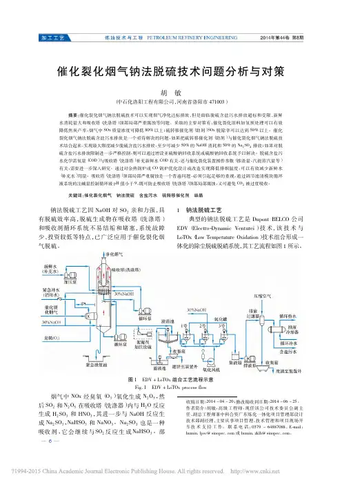
The FCC Flue Gas SOx Transfer Additive RFS Developed by RIPP
- 格式:pdf
- 大小:168.88 KB
- 文档页数:4
翻译部分英文原文Kinetic study of the reaction between sulfur dioxideand calcium hydroxide at low temperature in afixed-bed reactorAbstractA quantitative study of the influence of inlet sulfurdioxide concentration (600–3000 ppm),relative humidity (20–60%), reactortemperature(56–86℃)and different amounts (0–30 wt.%) ofinorganic additives(NaCl, CaCl2 andNaOH) on gas desulfurization has been carried out in acontinuous downflow fixed-bed reactor containing calcium hydroxide diluted with silica sand.Results show that the reaction rate does not depend on sulfur dioxide partial pressure (zero-order Kinetics) and that the temperature and the relative humidity have a positive influence on reactionrate. An apparent activation energy of 32 kJ/mol Ca(OH)2 has been estimated for the reaction.An empirical reaction rate equation at 71.5℃and 36.7% relative humidity that includes thetype and amount of additive is proposed. It has been found thatcalcium chloride is the bestadditive studied because it allows for a higher degree of sulfur dioxide removal. 2000 ElsevierScience B.V. All rights reserved.Keywords: Desulfurization; Sulfur dioxide; Calcium hydroxide; Kinetics; Inorganic additives1. IntroductionThe increasing concern during the last few years on the protection of the environmenthas had its influence on the design and operation of power plants, especially on thereduction of sulfur dioxide and nitrogen oxide emissions from them. They are the mainpollutants from coal and fuel-oil combustion in power plants. Both gases are responsiblefor acid rain.In USA and Europe, new power plants that use fuels with significant quantities ofsulfur have to meet severe standards to reduce these air pollutants. One of the majorproblems facing older power plants is that they were designed prior to the presentstandards for pollution control and therefore have no facilities on space to incorporatesuch controls.The technologies to control sulfur dioxide emissions can be distributed into threegroups by considering if the treatment is done before, during or after thecombustion. Itseems clear that the last group of technologies cited is the most advantageous, fromvarious points of view, for power stations which have been in operation for many years.These are called FGD technologies (Flue Gas Desulfurization),and among them, themost usedare: IDS (In-Duct Scrubbing, developed by General Electric); E-So x(developed by US EPA, Babcok and Wilcox, Ohio Coal Development Office and OhioEdison), EPRIHYPAS (Hybrid Pollution Abatement System, developed by ElectricPower Research Institute), DRAVO HALT (Hydrate Addition at Low Temperature,developed by Dravo), CONSOL COOLSIDE (developed by Consolidated CoalCom-pany)and ADVACATE(developed by Acurex and US EPA). These processes are basedon the injection of a solid sorbent plus water by spraying or injecting a slurry into theduct situated between the air preheater and the particulate collection system. Calciumhydroxide or limestone are usually used as sorbents to capture sulfur dioxide and acalcium sulfiter/sulfate mixture is obtained as the reaction product.Klingspor and Stromberg proposed a mechanism to explain the reactionbetween sulfur dioxide and calcium hydroxide or calcium carbonate in the presence ofwater vapor. According to them, when the relative humidity is low (below 20%), sulfurdioxide and water can be adsorbed on the solid surface, however, no reaction occursuntil there is at least a monolayer of water molecules adsorbed on the surface. As therelative humidity increases, less sulfur dioxide can be adsorbed on the surface becausewater adsorption on the solid occurs preferentially due to intermolecular forces. Thus,sulfur dioxide has to be absorbed on the adsorbed water, forming complexes where thesulfur atom isbound to the oxygen atom of water. This fact leads to the formation of apositive charged hydrogen atom that can combine with hydroxide or carbonate ions fromthe sorbent to form reaction intermediates and products. Experimental findings show thatthe reaction rates for lime and limestone are similar. Consequently, the complexformation SO2nH O is considered to be the rate-determining step, since all further reactions are different for the two types of sorbents. The initial rate of the process isindependent of sulfur dioxide concentration when the relative humidity is below 70%.Above this value, the reaction rate becomes gradually more and more dependent on thesulfur dioxide partial pressure. This fact can be attributed to the formation of stableconfigurations of water ligands around the sulfur dioxide molecules. Also, it has beenfound that the initial reaction rate is a very weak function of temperature but increasesexponentially with relative humidity, for both hydrated lime and limestone.Jorgensen also studied this reaction in a bench-scale sand bed reactor. Someof their conclusions point out that the calcium hydroxide conversion has a very strongdependence on relative humidity. The conversion rate is increased moderately withtemperature in agreement with activation energy of 25 kJ/mol. However, there is noclear indication of increasing conversion with increasing sulfur dioxide concentration.Ruiz-Alsop and Rochelle found that the relative humidity is the most importantvariable affecting the reaction of sulfur dioxide and calcium hydroxide. The chemicalreaction taking place at the surface of the unreacted calciumhydroxide presentszero-order kinetics in sulfur dioxide. At high relative humidity and/or high SO2concentration, the chemical reaction at the surface of the unreacted calcium hydroxidesolid controls the overall reaction rate. At low relative humidity and/or low sulfurdioxide levels, diffusion of sulfur dioxide through the solid product layer becomes therate-controlling step. The reaction rate has a weak temperature dependence. Theactivation energy of the reaction was estimated to be 12 kJ/mol.Experimental data by Krammer showed that the reaction ratedepends onthe sulfur dioxide concentration but only at low concentrations and not so obvious athigher concentrations. In contrast to other publications, they found that the influence ofSO2concentration on the reaction rate is rather linked to the conversion than to the 2relative humidity, which has a major impact on the conversion throughout the entirereaction as usually reported in literature. But they found out that the initial reaction rateseems to be independent of relative humidity and sulfur dioxide concentration, whichhad not been reported yet. They postulated that the reaction can be divided into thefollowing foursteps. During the initial stage, a chemisorption process of the sulfurdioxide on the particle surface seems to be important and the reaction rate decreasesexponentially with increasing conversion. Simultaneously, a nucleation processdominates the formation of the consecutive product layers where the reaction rateincreases with increasing relative humidity. The rate of reaction increases untilproduct layer diffusion takes over and reaction rate decreases again with conversion. Itshould be noted that only relative humidityhas an impact on product layer diffusion. Beyond a conversion of around 9%, reaction rate drops significantly, which can be dueto pore closure.Irabien consider the adsorption of sulfur dioxide on calcium hydroxideacting as a nonideal solid sorbent is the rate-limiting step. They use a parameterreferring to this nonideal behavior of the solid surface as independent of temperature butexponentially dependent on relative humidity. The authors obtained activationenergy of75 kJ/mol for the reaction.All published work thus far indicates that relative humidity has the greatest impact onthe reaction rate between sulfur dioxide and calcium hydroxide. The relative humidity isin turn correlated with the moisture content of the solids. Additives that will modify themoisture content of the calcium hydroxide solids in equilibrium with a gas phase of agiven relative humidity would then be expected to enhance the reactivity of calciumhydroxide towards sulfur dioxide in FGD processes.Organic and inorganic additives have been tested in spray dryer systems to improvethe desulfurization power of calcium hydroxide and calciumcarbonatew.It seems that inorganic hygroscopic salts such as barium, potassium, sodium and calciumchlorides and also cobalt, sodium and calcium nitrates would be the most effective ones.Some researchers also consider sodiumhydroxide as an effective additive due to itsalkaline and hygroscopic properties.Ruiz-Alsop and Rochelleindicated that deliquescence alone does notexplainthepositive effect of some salts. They contend that for an additive to be effective, it is alsonecessary that the hydroxide of the cation be very soluble, otherwise, the cation willprecipitate out as the hydroxide and the anion will form the calcium salt which could notbe hygroscopic. The effectiveness of a certain salt also depends on the relative humidity.This could be expected because when therelative humidity of the gaseous phase islower than the water activity in a saturated solution of the salt, it would not absorb waterand so, it would not enhance the calcium hydroxide reactivity. These researcherscontend that chlorides and sodium nitrate modify the properties of the product (half-hy-drated calcium sulfite) layer that is formed as the reaction takes place, therebyfacilitating the access of sulfur dioxide to unreacted calcium hydroxide, which remainsin the interior of the particle.The scope of the present work is to quantify the influence on the reaction rate ofsulfur dioxide concentration, relative humidity, temperature and type and amount ofadditive. An empirical equation, which relates the reaction rate with these variables, hasbeen obtained and an apparent activation energy value for the reaction has also beendetermined from kinetic constants at different temperatures by using the Arrhenius plot.2. Experimental sectionThis equipmentconsists of a continuous feeding and humidification system of a gaseous stream, afixed-bed reactor and an analytical system. The apparatus is operated with a personalcomputer using LabView software (NationalInstruments), which allows programmingand control of the experimental conditions, namely, nitrogen and sulfur dioxide flowrates, humidification temperature and electric resistance heating of the pipes to avoidcondensations and also provides the experimental data acquisition, in particular nitrogenand sulfur dioxide flow rates, reaction temperature, pressure, relative humidity andsulfur dioxide concentration, vs. reaction time.Simulated flue gas was obtained by mixing sulfur dioxide and nitrogen from separatecylinders in appropriate amounts using mass flow controllers Before mixing, pure nitrogenwas passed (by switching on valve 1 from thecomputer)through the humidificationsystemthat consisted of three cylindrical flasks with 200 ml of watereach submerged into a thermostatic bath. Each flask contains small glass spheres toimprove the contact between gas and water. After the humidification system, thetemperature and the relative humidity of the wet nitrogen were measured by using aVaisala HMP 235 transmitter .At the same location, the pressure was alsoMeasuredto calculate the flow rate of water vapour generated. Thewet nitrogen by-passed the reactor until the desired experimental conditionswerereached and then valve 2 was opened from the computer to allow thegaseous streamflow through the reactor. The bed was always humidified for 15 min while the sulfurdioxide analyser was set to zero. At this time, the desired flow of sulfur dioxide wasintroduced by a mass flow controller and the experiment began. Data generated duringthe experiment were stored in an EXCEL format computer file.The glass reactor, a jacketed Pyrex tube (450 mm height, 12 mm i.d.)with a porousplate to hold 1 g of dry calcium hydroxide (Probus, 99% purity and particle size smallerthan 0.05 mm in diameter)or calcium hydroxide–additive mixtures(all additives weresupplied by Fluka, 99% purity and particle size smaller than 0.05 mm in diameter) diluted with 8 g of silica sand (Merck;0.1–0.3 mm in diameter)to assure isothermaloperation and to prevent channelling due to excessive pressure drop, was thermostatedby pumping a thermal fluid (water–ethyleneglycol mixture) from an external thermostaticbath.The reacted flue gas is passed through a refrigeration systemin orderto remove water because it interferes with the SO2 analyser measurement.The output from the analyser was continu-ously collected by the computer for 1h (experiment time)and the concentration (ppm) of sulfur dioxide stored as a function of time (experimental curve). Each experiment wasconducted in the same manner except a reactive solid was substituted for the10 g ofinert silica(‘‘blank’’ experiment) to obtain a reference flow curve. The reaction rate wascalculated as SO2mol removed/h mol OH-from the area enclosed by the two curves (experimental and ‘‘blank’’). Some experiments were replicated to estimate the experimentalerror in reaction rate.3. ConclusionsIn this research, the quantitative influence of sulfur dioxide concentration, temperature,relative humidity and the type and amount of the three inorganic additives on thereaction rate between calcium hydroxide and sulfur dioxide have been determined.The SO2concentration (0–3000 ppm)was shown to have no significantinfluence on the reaction rate at a relative humidity of 38% and at 71.5℃. These results agree withthose of Ruiz-Alsop and Rochelle who indicated that sulfur dioxide concentrationdoes not influence the reaction rate at temperatures ranging from 30℃to 90℃; 17–90%relative humidity and sulfur dioxide concentration varying from 0 to 4000 ppm. Sinceour experiments are within the range of these experimental conditions, we assume thatsulfur dioxide concentration will not influence the reaction rate at our other experimentalconditions also.An empirical rate equation, which allows us to quantify the influence of temperatureand relative humidity on reaction rate has been developed and an apparent activationenergy of 32 kJ/mol Ca(OH)2 has been calculated. This value, relatively high, demonstrates the weak influence of temperature, but the reaction order of 1.2 withrespect to the relative humidity shows its strong influence on reaction rate.Three inorganic additives were tested to evaluate their quantitative influence onreaction rate. An empirical equation for each additive at 71.5℃and a relative humidityof 36.7% was developed.The kinetic rate constants for calcium chloride, sodium hydroxide and sodiumchloride were found to be respectively, 9, 5 and 0.81 times the rate constant for calciumhydroxide without any additive. The reaction orders for the weight ratio of the sameadditives were 0.6, 0.52 and y0.12, respectively. Calcium chloride is the best additivewhereas sodium chloride is an inhibitor.中文译文动力学研究与二氧化硫反应在低温和氢氧化钙在一固定床反应器摘要一个入口二氧化硫浓度(600-3000百万分之一),相对湿度(20-60%),反应器温度(影响的定量研究56-86℃)和不同的金额(0-30%重量)ofinorganic添加剂(氯化钠,氯化钙和氢氧化钠)对气体脱硫已进行acontinuous下行流了固定床反应器含有氢氧化钙与氧化硅sand.Results 稀释表明,反应速度不依赖于二氧化硫分压(零阶动力学),而温度和相对湿度对reactionrate积极的影响。
附录一Flue gas desulfurizationFlue gas desulfurization is commonly known as FGD and is the technology used for removing sulfur dioxide (SO2) from the exhaust flue gases of power plants that burn coal or oil to produce steam for the turbines that drive their electricity generators. The most common types of FGD contact the flue gases with an alkaline sorbent such as lime or limestone. [1][2][3] As sulfur dioxide is responsible for acid rain formation, stringent environmental protectionregulations have been enacted in many countries to limit the amount of sulfur dioxide emissions from power plants and other industrial facilities.Prior to the advent of strict environmental protection regulations, tall flue gas stacks (i.e., chimneys) were built to disperse rather than remove the sulfur dioxide emissions. However, that only led to the transport of the emissions to other regions. For that reason, a number of countries also have regulations limiting the height of flue gas stacks.For a typical conventional coal-fired power plant, FGD technology will remove up to 99 percent of the SO2 in the flue gases.∙Contents∙ 1 History∙ 2 FGD chemistry∙ 3 Types of FGD systemso 3.1 Spray towero 3.2 Spray-dryero 3.3 Dry sorbent injection∙ 4 Sulfur dioxide emission removal performance levels∙ 5 Facts and statistics∙ 6 Alternative methods of reducing sulfur dioxide emissions∙7 Sulfuric acid mist formation∙8 ReferencesHistoryMethods for removing sulfur dioxide from flues gases have been studied for over 150 years. Early concepts useful for flue gas desulfurization appear to have germinated in 1850 in England.With the construction of large-scale power plants in England in the 1920s, the problems associated with large volumes of SO2emissions began to concernthe public. The problem did not receive much attention until 1929, when the British government upheld the claim of a landowner against the Barton Electricity Works for damages to his land resulting from SO2 emissions. Shortly thereafter a press campaign was launched against the erection of power plants within the confines of London. This led to the imposition of SO2 controls on all such power plants.[4]During this period, major FGD installations went into operation in England at three power plants. The first one began operation at the Battersea Station in London in 1931. In 1935, the second one went into service at the Swansea Power Station. The third one was installed in 1938 at the Fulham Power Station. All three installations were abandoned duringWorld War II.Large-scale FGD units did not reappear in commercial operation until the 1970s, and most of the activity occurred in the United States and Japan.[4] As of June 1973, there were 42 FGD units, ranging in size from 5 to250 megawatts, in operation: 36 in Japan and 6 in the United States.[5]As of about 1999-2000, there were 678 FGD units operating worldwide (in 27 countries) producing a total of about 229 gigawatts. About 45% of that FGD capacity was in the United States, 24% in Germany, 11% in Japan and 20% in various other countries. Approximately 79% of the units, representing about 199 gigawatts of capacity, were using lime or limestone wet scrubbing. About 18% (or 25 gigawatts) utilized spray-dry scrubbers or dry sorbent injection systems.[6][7][8]FGD chemistrySO2 is an acid gas. Therefore, the most common large-scale FGD systems use an alkaline sorbent such as lime or limestone to neutralize and remove the SO2 from the flue gas. Since lime and limestone are not soluble in water, they are used either in the form of an aqueous slurry or in a dry, powdered form. When using an aqueous slurry of sorbent, the FGD system is referred to asa wet scrubber. When using a dry, powdered sorbent, the system is referred to as a dry system. An intermediate or semi-dry system is referred to asa spray-dry system.The reaction taking place in wet scrubbing using a CaCO3 (limestone) slurry produces CaSO3 (calcium sulfite) and can be expressed as:CaCO3 (solid) + SO2(gas) → CaSO3 (solid) + CO2 (gas)When wet scrubbing with a Ca(OH)2 (lime) slurry, the reaction alsoproduces CaSO3 (calcium sulfite) and can be expressed as:Ca(OH)2 (solid) + SO2(gas) → CaSO3 (solid) + H2O (liquid)When wet scrubbing with a Mg(OH)2 (magnesium hydroxide) slurry,the reaction produces MgSO3 (magnesium sulfite) and can beexpressed as:Mg(OH)2 (solid) + SO2(gas) → MgSO3 (solid) + H2O (liquid)Some FGD systems go a step further and oxidize theCaSO3 (calcium sulfite) to produce marketable CaSO4 · 2H2O(gypsum):CaSO3 (solid) + ½O2 (gas) + 2H2O (liquid) → CaSO4 · 2H2O (solid)Aqueous solutions of sodium hydroxide (known as causticsoda or simply caustic) may also be used to neutralize andremove SO2 from flue gases. However, caustic soda islimited to small-scale FGD systems, mostly in industrialfacilities other than power plants because it is moreexpensive than lime. It has the advantage that it forms asolution rather than a slurry and that makes it easier tooperate. It produces a solution of sodium sulfite or sodiumbisulfite (depending on the pH), or sodium sulfate that mustbe disposed of. This is not a problem in a paper mill forexample, where the solution can be recycled and reusedwithin the paper mill.Types of FGD systemsThe major types of large-scale, power plant FGD systemsinclude spray towers, spray dryers and dry sorbent injectionsystems.Spray towerThere are various types of wet scrubbers. For example, spraytowers, venturi scrubbers, packed towers and trayed towers. Slurries would cause serious erosion problems in a venturi scrubber because of the high speeds at the throat of the venturi section. Packed towers or trayed towers would plug up if handling slurries. For handling slurries, the spray tower is a good choice and it is in fact a commonly used choice in large-scale FGD systems.[3][9][10]Spray towers are used downstream of the particulate equipment (electrostatic precipitator or baghouse) where the flue gas contains very little, ifany, combustion fly ash. In a spray tower system, the sorbent slurry is simply injected via spray nozzles into a vertical tower where the slurry droplets are contacted with the upflowing flue gas.Part of the water in the slurry is evaporated by the hot flue gas and the flue gas becomes saturated with water vapor.The SO2 dissolves into the slurry droplets and reacts with the alkaline sorbent particles. The slurry falls to the bottom of the spray tower and is sent to a reaction tank where the reaction is completed and a neutral salt is formed. In a regenerable system, the residual slurry is recycled back for reuse in the spray tower. In a once-through system, the residual slurry is dewatered and either disposed of or oxidized to CaSO4 · 2H2O and sold as a by-product gypsum. Spray-dryerSpray-dryers are used upstream of the particulate removal equipment (electrical precipitator or baghouse) where the flue gas contains the combustion fly ash. In a spray-dryer system, the alkaline sorbent is usually lime slurry. The slurry is atomized and sprayed into a vessel as a cloud of fine bubbles where it contacts the hot flue gas. The water is completely evaporated by the hot gas and the residence time in the vessel (about 10 seconds) allows the SO2 and any other acid gases, such as SO3 and HCl, to react with the lime to form a dry powder of calcium sulfite, calcium sulfate and unreactedlime.[3][11][12]The dry powder is removed from the flue gas along with the combustion fly ash in the particulate removal equipment. Some of the solids from the particulate removal equipment (i.e., fly ash, calcium sulfite, calcium sulfate and unreacted lime) may be recycled and reused as part of the sorbent slurry.[12]Dry sorbent injectionThe dry FGD system simply injects powdered lime or limestone sorbent directly into the flue gas. As shown in the adjacent location diagram, the dry sorbent may be injected into any one of three locations: (1) the upper section of the steam generator, (2) the economizer section of the steam generator orthe ducting between the air preheater and the electrostaticprecipitator.[2][3][11][13]The powdered sorbent is pneumatically injected through lances designed to distribute the sorbent evenly across the flow path of the flue gas.When injected into the upper section of the steam generator, it should enter at a point where the temperature range is about 900 to 1200 °C. Injection into the economizer should be at a point where the temperature range is about 400 to 600 °C. Injection into the ducting between the preheater and the precipitator should be at point where the flue gas temperature is about 150 to 180 °C.[3][11] The SO2 reacts directly with the powdered sorbent and the spent sorbent is removed from the flue gas along with the combustion fly ash inthe particulate removal equipmentSulfur dioxide emission removal performance levelsPartial flue gas desulfurization (FGD) can achieve about 50-70 % removal of sulfur dioxide by the injection of dry limestone just downstream of the air preheater. The resultant solids are recovered in the electrostatic precipitators along with the fly ash.In power plants burning pulverized coal, wet flue gas desulfurization (FGD) that contacts the flue gases with lime slurries (in what are called wet lime scrubbers) can achieve 95% sulfur dioxide removal without additives and99+% removal with additives. Wet FGD has the greatest share of the FGD usage in the United States and it is commercially proven, well established technology.[14]The typical older FGD units in power plants burning pulverized coal within the United States achieve average sulfur dioxide emission levels of about 0.340 kg/MWh (0.22 lb SO2 /106Btu), which meets the level to which those units were permitted.The lowest demonstrated sulfur dioxide emission level (in 2005) for power plants burning pulverized high-sulfur coal within the United States was 1.08 kg/MWh (0.07 lb SO2 /106 Btu) and 0.046 kg/MWh (0.03 lb SO2 /106 Btu) for plants burning low-sulfur pulverized coal.[14]Facts and statisticsFlue gas desulfurization scrubbers have been applied to combustion units firing coal and oil that range in size from 5 MW to 1500 MW. ScottishPower are spending £400 million installing FGD at Longannet powerstation which has a capacity of over 2 GW. Dry scrubbers and sprayscrubbers have generally been applied to units smaller than 300 MW.Approximately 85% of the flue gas desulfurization units installed in the US are wet scrubbers, 12% are spray dry systems and 3% are dry injection systems.The highest SO2 removal efficiencies (greater than 95%) are achieved by wet scrubbers and the lowest (less than 80%) by dry scrubbers. However, the newer designs for dry scrubbers are capable of achieving efficiencies in the order of 90%.The capital, operating and maintenance costs per short ton ofSO2 removed (in 2001 US dollars) are:∙For wet scrubbers larger than 400 MW, the cost is $200 to $500 per ton∙For wet scrubbers smaller than 400 MW, the cost is $500 to $5,000 per ton∙For spray dry scrubbers larger than 200 MW, the cost is $150 to $300 per ton∙For spray dry scrubbers smaller than 200 MW, the cost is $500 to $4,000 per tonAlternative methods of reducing sulfur dioxide emissions An alternative to removing sulfur from the flue gases after burning is to remove the sulfur from the fuel before or duringcombustion. Hydrodesulfurization of fuel has been used for treating fuel oils.Fluidized bed combustion adds lime to the fuel during combustion. The lime reacts with the SO2 to form sulfates which become part of thecombustion ash.Sulfuric acid mist formationFossil fuels such as coal and oil contain significant amounts of sulfur.When burned, about 95 percent or more of the sulfur is generallyconverted to sulfur dioxide (SO2). This happens under normal conditions of temperature and of oxygen present in the flue gas. However, there are circumstances under which this may not be the case.For example, when the flue gas has too much oxygen and the SO2 isfurther oxidized to sulfur trioxide (SO3). Actually, too much oxygen is only one of the ways that SO3 is formed. Gas temperature is also an important factor. At about 800 °C, formation of SO3 is favored. Another way thatSO3 can be formed is through catalysis by trace metals in the fuel. This is particularly true for heavy fuel oil, where small amounts of vanadium are present. In whatever way that SO3 is formed, it does not behave likeSO2 in that it forms a liquid aerosolknown as sulfuric acid (H2SO4) mist that is very difficult to remove. Generally, about 1% of the sulfur dioxide will be converted to SO3. Since SO3 an acid gas, just as is SO2, it is also removed by the alkaline sorbents used in FGD systems.References1. ↑ Karl B. Schnelle and Charles A. Brown (2001). Air PollutionControl Technology>. CRC Press. ISBN 0-8493-9599-7.2. ↑2.02.1 SO2 Control Technologies (from website of the Institute ofClean Air Companies)3. ↑3.03.13.23.33.43.5 Air Pollution Control Technology Fact Sheet U.S.EPA publications EPA-452/F-03-0344. ↑4.04.1 Biondo, S.J. and Marten,J.C., A History of Flue GasDesulfurization Systems Since 1850, Journal of the Air PollutionControl Association, Vol. 27, No. 10, pp 948-961, October 1977.5. ↑ Beychok, Milton R., Coping With SO2, ChemicalEngineering/Deskbook Issue, October 21, 19746. ↑ Nolan, Paul S., Flue Gas Desulfurization Technologies forCoal-Fired Power Plants, The Babcock & Wilcox Company, U.S.,presented by Michael X. Jiang at the Coal-Tech 2000 InternationalConference, November, 2000, Jakarta, Indonesia7. ↑ Rubin, E.S., Yeh, S., Hounsell, D.A., and Taylor,M.R., Experience curves for power plant emission controltechnologies, Int. J. Energy Technology and Policy, Vol. 2, Nos. 1/2,20048. ↑ Beychok, Milton R., Comparative economics of advancedregenerable flue gas desulfurization processes, EPRI CS-1381,Electric Power Research Institute, March 19809. ↑ Wet FGD System Materials Cost Update, by M.G. Milobowski,Babcock & Wilcox (Presented at EPRI-DOE-EPA Combined UtilityAir Pollutant Control Symposium, August 1997)10. ↑ Air Pollution Control Technology Fact Sheet U.S.EPA publications EPA-452/F-03-01611. ↑11.011.111.2 IEA Clean Coal Center: Spray dry scrubbers forSO2 removal12. ↑12.012.1 Dry Flue Gas Desulfurization (FGD)Systems (FromBabcock and Wilcox website)13. ↑ Barbara Toole-O'Neil and Ohio Coal Development Office (Editors)(1998). Dry Scrubbing Technologies for Flue Gas Desulfurization.Springer. ISBN 0-7923-8346-X.14. ↑14.014.1 Dr. James Katzer et al and MIT Coal Energy StudyAdvisory Committee (2007).汉语翻译烟气脱硫烟气脱硫,就是泛指用烟气脱硫技术电厂燃烧煤、石油化工或其他工业废气中除去硫氧化物的技术。
垃圾焚烧发电厂生产流程英文回答:Waste-to-Energy (WtE) Power Plant Process Flow.Waste-to-energy (WtE) power plants convert non-recyclable waste into electricity and heat. The process involves several key stages:1. Waste Acceptance and Sorting: Waste is delivered to the plant and subjected to preliminary sorting to remove recyclable materials and hazardous substances.2. Waste Preparation and Storage: Non-recyclable waste is shredded or pulverized to reduce its size and increase its surface area. The shredded waste is then stored in bunkers or silos until ready for combustion.3. Combustion: The shredded waste is fed into a combustion chamber and burned at high temperatures in acontrolled environment. The combustion process generates heat and releases flue gases.4. Heat Recovery: The heat generated by combustion is captured by a boiler to produce steam. The steam is then used to drive a turbine generator to produce electricity.5. Flue Gas Cleaning: The flue gases produced during combustion contain pollutants such as particulates, sulfur oxides (SOx), and nitrogen oxides (NOx). These gases are cleaned using various technologies, such as scrubbers, electrostatic precipitators, and selective catalytic reduction (SCR) systems.6. Ash Handling: The combustion process produces bottom ash and fly ash. Bottom ash is removed from the combustion chamber and quenched with water. Fly ash is collected from the flue gas cleaning system. Both types of ash are disposed of or recycled.7. Energy Distribution: The electricity generated by the WtE plant is distributed to the power grid and can beused to power homes, businesses, and other consumers. The heat generated can also be used for district heating or other industrial purposes.中文回答:垃圾焚烧发电厂生产流程。

垃圾焚烧发电厂的脱硫脱硝工艺English Answer:Flue Gas Desulfurization (FGD) and De-nitrification (DeNOx) Techniques in Waste Incineration Power Plants.Incineration of waste materials, particularly municipal solid waste (MSW), generates flue gases that contain various pollutants, including sulfur oxides (SOx) and nitrogen oxides (NOx). To mitigate the environmental impact of these pollutants, flue gas treatment systems are employed in waste incineration power plants. This article provides an overview of the commonly utilized FGD and DeNOx technologies for controlling SOx and NOx emissions, respectively.Flue Gas Desulfurization (FGD)。
FGD systems are designed to remove sulfur dioxide (SO2) from flue gases. Sulfur dioxide is a harmful pollutant thatcan contribute to acid rain and respiratory problems. The most common FGD technologies include:Wet Scrubbing: This method utilizes a scrubbing liquid, typically limestone or lime slurry, to absorb SO2 from the flue gases. The scrubbing liquid is then treated to remove the captured sulfur.Dry Scrubbing: In this process, a dry sorbent, such as lime or sodium bicarbonate, is injected into the flue gases. The sorbent reacts with SO2 to form a solid product, whichis removed from the system.Spray Dry Absorption: This technique combines features of both wet and dry scrubbing. A scrubbing liquid issprayed into the flue gases, which then reacts with a dry sorbent to form a solid product that is removed.De-nitrification (DeNOx)。
Blue carbon is also called carbocoal ,coke powder, is made by using high quality Jurassic clean coal block teemed with ShenFu coalfield, as a kind of new type carbon materials, with its high fixed carbon, high specific resistance, high chemical activity, low ash content, low aluminum content, low sulfur content and low phosphorus characteristics, gradually replace metallurgical coke and widely used in calcium carbide, ferroalloy, ferrosilicon, Silicon carbide and other products production, become a kind of irreplaceable carbon materials.Blue carbon (people also say semicoke, coke), structure for massive, the grain size general above 3 mm, the pale black color, at present, blue carbon basically have two kinds of specifications: one is the soil refined blue carbon, the other is machine-made blue carbon. Although two specifications blue carbon uses the same quality coal refining into, but because of the different production technology and equipment, its cost and quality are different.Blue carbon dryer is mainly composed by the barrel, transmission device, riding wheel device, raising material plate, sealing equipment etc. Our company with many years of practical experience developed new high efficiency energy saving rotary dryer. Compared with the traditional rotary dryer, the drying efficiency is higher, energy consumption is lower, yield is higher, running is more stable, sealing is better, widely adaptive and deeply user’s praise and recognition.The main performance characteristics1, heat source select fluidized bed furnace:Fuel of this type wide adaptability, can use all sorts of coal, especially use almost no volatile coke or coke breeze. Combustion temperature is lower, inburning process can effectively control the emissions of Nox and Sox, is a "clean" combustion technology, burn-off rate is high, high thermal efficiency; great section thermal intensity, the bed layer’s heat transfer ability is high, can reduce the furnace hearth volume and steel consumption. Load regulation broad/covering a wide range, heating stability properties is good, Ignition convenient, damping-down time is long, lime-ash is not easy to soften or cementation, activity good, easy to comprehensive utilization.2, efficiently combination raising material plateAccording to the physical property changes in the drying process of the material, uses many kinds of structure of combination raising material plate, make the material in the cylinder to form even material curtain, and with the hot flue gas fully proceed heat transfer and mass transfer, as to the high humidity viscous material, will have the jam resistance materials and break to accumulate the ball chain device. As to good liquidity material, the spoon-type of arc plate, etc. So let the unit volume evaporation strength reach to 40 ~ 80 kg/m3. H, evaporation strength improve 50 ~ 100% than the traditional rotates dryer.3, “Adjust center” riding wheel deviceUsing bearing type and structure form which different from the traditional dryer’s riding wheel, riding wheel and tyre self-constrain and keep line contact, the friction surface contact more board and equilibrium, to ensure the service life of riding wheel and tyre, enhance the cylinder operation stability. And properly reduce included angle between riding wheels, reduce operation resistance, lower power consumption.4, reasonably adjust rotate speedAccording to differ physico-chemical properties of drying material, drying retention time are different, design adopts the best rotate speed operation, fullyguarantee the drying quality, general equip with electromagnetic speed regulation motor or frequency control motor speed motor.5, design of dust collecting tail coverAccording to the requirements of different dry material, enlarge cavity design tail cover and change the exhaust flow, let the tail cover to get primary role to collect dust, greatly reducing the collect dust pressure to subsequent dust collector.6, new type sealing deviceThe dryer’s before and after seal ring take example by rotary kiln seal device, composed by maze/ labyrinth device, heat resistance andwear-resisting, sealed performance is good, long service life, convenient installation and maintenance.technical parametersHZG2200X20 70Y225M-630 JZQ750 20000X3620X3570 36.07 HZG2400X24 63.3 3.85Y225M-630 JZQ850 14000X3860X3760 59.9HZG2800X24 147.8 Y225M-675 JZQ850 15000X4060X3960 97HZG320025 176.5 5Y225M-675 JZQ1000 25000x5000x4500 110。

0引言随着快速的经济增长和资源需求增加,中国正在面临一系列的环境污染问题,特别是燃煤产生二氧化硫污染环境问题。
由于受到经济的限制,大部分燃煤燃烧前不经过脱硫处理,严重污染了环境。
现在公认的脱硫过程是烟气脱硫过程,是控制二氧化硫污染的主要方式,石灰石(石灰)-石膏湿法脱硫技术采用廉价的石灰石或石灰作为脱硫吸附剂,因其具有脱硫效率高、运行稳定,运行费用低等特点,得到了广泛的应用。
脱硫石膏是石灰石(石灰)/石膏经湿法烟气脱硫基金项目:宁夏大学自然科学研究基金(ZR1340)。
第一作者简介:王静,女,1981年出生,山东烟台人,助理研究员,硕士,主要从事盐碱地改良与农业生态方面的研究。
通信地址:750021宁夏银川市西夏区贺兰山西路539号宁夏大学新技术应用研究开发中心,Tel :0951-*******,E-mail :wangjing@ 。
通讯作者:许兴,男,1959年出生,宁夏银川人,教授,博士,主要从事农业生理生态方面的研究。
通信地址::750021宁夏银川市西夏区贺兰山西路489号宁夏大学农学院,Tel :0951-*******,E-mail :xuxingscience@ 收稿日期:2015-03-06,修回日期:2015-07-23。
脱硫石膏对植物和土壤的影响王静1,2,肖国举1,许兴2(1宁夏大学新技术应用研究开发中心,银川750021;2宁夏大学农学院,银川750021)摘要:煤炭燃烧产生二氧化碳、氧化硫、氧化氮和各种副产物,包括粉煤灰,燃煤烟气,沉淀物等。
脱硫石膏是以钙基物质作为吸收剂,将SO 2以硫酸钙的形式固定下来,最终生成的一种烟气脱硫副产物。
脱硫石膏因其含有丰富的必需元素,尤其硼和硫元素含量丰富,影响着植物体的生长和土壤的物理化学性质,使得脱硫石膏在农业上的应用得到了广泛发展。
笔者简要概述了脱硫石膏的性质,及其对环境的影响,尤其现阶段脱硫石膏在盐碱地改良中的应用。
大量的田间试验表明脱硫石膏在农业生产中是有效而且安全的土壤改良剂,但是缺乏和过量施用脱硫石膏引起的生物学过程和相互作用还有待研究。
城市生活废弃物焚烧发电行业专业英语强化大纲(第一版)广州广日集团有限公司环境产业事业部2007年10月30日目录一、城市生活废弃物行业设备专用词汇/组二、城市生活废弃物行业相关词汇/组三、城市生活废弃物行业相关文章四、城市生活废弃物行业相关图片一、城市生活废弃物行业设备专用词汇/组The VølundSystems™ Waste Fired Power Plant System consists ofVølundSystems™ boiler & combustion technology for various Waste fuels: - VølundSystems™ boiler technology- VølundSystems™ waste combustion grate technology- VølundSystems™ pusher feeding technology- VølundSystems™ ash pusher technologyBoilerWater tube boiler incl. boiler drumSuperheatersEconomizersBoiler internal pipingWater injection valves and de-superheaterWaste charging stationWaste charging hopperWaste charging chuteCooling system for chuteWaste feeding damperFeeding pusherHydraulic cylinders for damper and feeding pusherWaste level detecting unit for chuteGrate combustion systemAir cooled combustion gratesHydraulic cylindersSNCR reagent InjectionSNCR reagent injection systemSteel construction. IncineratorSteel cassing, furnaceFrame for furnaceHoppers below grates and pusher Clinker chuteInspection doors in furnace Sealing between boiler and furnace Slag and sifting systemSlag pusherSifting wet conveyorsSlag vibration conveyorSlag distributorSealing plate for slag distributor Slag and metal chuteSlag pit screenMagnet separatorMetalic conveyorFansPrimary Air FanSecondary Air FanCooling Air Fan for pusher SilencersAirpreheater (combustion air) Airpreheater - air / sat water Arprejeater - air / steamAuxiliary Burner SystemOil burnerIgnition burnerOil pipesPumps and valvesTankDucts SystemPrimary air ductSecondary air ductCooling air ductDampersCompensatorsVenturiesFlue Gas DuctsDuct: Boiler - Precipitator -FGCDuct: FGC- ID fanDuct: ID fan - chimneyGalleries / StairsGalleries for boiler and incineratorSupportsBoiler structur and support (incl Eco-tower)Make up water systemMake up water pumpDearatorFeed water pumps.Pipe systemThe overall water/steam circuitHP steam pipes from boiler outlet to consumer (turbine, exchanger, ect….) Steam pipes for sootblowersCondensate pipes from turbine system to feed water tankFrom outlet feed water tank to boiler inlet box.Water injection pipesDrain and vent for the water/steam circuitDrain and vent for the boilerOther drain and vent pipesBlow down system and tankPipes for upstarts valves and safty valvesOil pipes and oil tanksCooling water systemPipework hangers and supportsValves etcAll valves for the water/steam circuitAll valves for the boiler systemAll valves for the oil systemAll valves for the cooling systemAll valves for the soot blowers systemSafty valves and silincers for boilerStart-up valves and silincers for boilerWater injection valves for boilerBleed test cooler and sampling system after FW-tank Bleed test cooler and sampling system after FW-pumps Bleed test cooler and sampling system after super heater Bleed test cooler and sampling system in boiler drum Boiler Cleaning SystemSoot blowers for eco partSoot blowers for boilerSoot blowers for super heatersRapping deviceFly Ash SystemWater cooled conveyor under 2 .passRotary sluice under 2. passRotary sluice under eco. passFly ash system from boilerFly ash transport system to ash siloHydraulicHydraulic systemCylinders at grates, waste feeding pusher and feeding damper Pipes incl. hosesRefractoryBoiler refarctoryFurnace refractoryInconelThermal insulation /claddingBoilerFlue gas ductsCombustion air ductsPipe line systemFinish PaintingPainting - completeFuel Handling System / CranesRefuse cranCrane chair etcPolygrabSkyclamber (for boiler inspection)Service cranesWater Treatment SystemWater Treatment System - completePneumatic SystemPneumatik System - completeChemical Dosing SystemChemical Dosing System - completeElectrical equipmentMotorsFrequency convertersMotor control center (MCC)Emergency diesel and UPSElectrical cablingGrounding and earthling protectionControl & InstrumentationDCS systemSafety systemCCTVField instrumentation for BWV scopeElectrical actuators for BWV scopePneumatic actuators for BWV scopeI/O list for feeding equipment, grate and slag pusher Control philosophy for automatic combustion control system PLC for boiler and grateSpare parts and toolsStrategic spare partsWear partsSpecial toolsSpare parts for BWV equipmentPID diagrams for the following systemsMass and heat balance for boiler systemDraf layout drawingOperation & maintenance manual for boiler and grate Documentation for boiler and grate control philosophy Training document for boiler and grateBasic drawings in 2D includering:Arrangement of boiler and economiserArrangement of boiler drumArrangement of backstaysStress calculation according to EN 12952 Specification of material according to EN 12952 Material list and weight listBoiler Pipe list.Boiler LoadsManufacturing drawingsTypical PID diagram/Basic designBasic designConceptual design dataBasic drawingsTypical PID Diagram/Conceptual designBasic drawingsConceptual design dataTypical PID diagramConceptual design dataTechnical guidelinesTypical PID diagramConceptual design dataOverall layout drawingBrief description of gallery placementSteel structure, basic drawingEquipment loadsPriliminar load planTypical PID diagram, SpecificationTypical PID diagram/Conceptual design data SpecificationsConceptual design data for grab capacity. Conceptual design and data for water qualityBasic requirementsStated at the PID diagram, SpecificationInstrumentation list.Stated at the PID diagram, SpecificationLogic diagramsPID diagramsSystem description1. Calculating instruction1.1. Thermal calculating instruction (every section of boiler, e.g. superheater, Economizer, airpreheater,evoporator,water-cooled wall)1.2. Resistance and pressure calculating instruction for fans (primary and secondary fan) and flue gas (from combustion room to eco.)1.3. Boiler erection instruction1.4. Boiler operation instruction1.5. Surface Temperature of Superheater calculating instruction1.6. De-superheater diathermancy (thermal or heat transfering) calculating instruction1.7. Capacity calculating of releasing steam of Safety valve1.8. Boiler water steam circuit and resistance calculating instruction1.9. Intensity(load limitation) of pressed parts and apparatus calculating instruction 1.10. Intensity(load limitation) of boiler steel structure calculating instruction1.11. Intensity(load limitation) of boiler drum support and suspend calculating instruction2. OVERALL drawings2.1 OVERALL boiler drawings2.2 OVERALL parts of superheater2.3 OVERALL parts of Eco. Drawings2.4 OVERALL parts of air preheater2.5 OVERALL parts of Boiler steel structure2.6 Load and burden of groundwork or foundation二、城市生活废弃物行业相关词汇/组Environmental impact analysisCivil buildingTendering/ biddingConstruction/ ErectionCommissionGenerationTurbinePower stationTrail runCommercial runMunicipal wasteBiomass/straw/wood chipsSludgeLandfillCompost/dunghillThe waste hierarchyDioxin reductionWaste reductionCo-generation from wasteWaste Fired Power Plant technologysolution for China’s mounting problems with waste Value concept tailored for low heating value waste fuel Minimum LHVDesign ValueMCR PointMaximum ValueNominal capacitySteam dataSteam generationFeed water temperatureElectricity outputTurbine GeneratorSymbolsAcronymsAbbreviationRelated Terms & GlossaryACC - Automatic Combustion Control system, a system that optimizes the combustion process.Acceleration - A vector quantity that specifies rate of change of velocity.APC - Air Pollution Control system. A system that reduces emissions =FGCBOO- Build Own OperateBOOT – Build Own Operate TransferCFD – Computational Fluid Dynamic is a numerical tool for calculating flow patterns, combustion, particle transport, thermal loads etc. inside a furnace and boiler.CHP – Combined Heat and Power a method of increasing overall efficiency of a WFPP by generating heat as well as power at the same time from the fuel.CMS – Control and Monitoring System.CO – Carbon monoxide.CO2- Carbon dioxide.Co-generation – see CHPCombustible waste- Waste which can be combusted.Combustion – the process of burning.Compost / composting – is a common name for humus, which is the result of thedecomposition of organic matter, Composting occurs naturally in most environments, such as in landfills.deNOX – NO x reductionDioxin – umbrella term for more than 200 organic compounds, 17 of which are highly toxic and are enriched in fatty tissueEPC – Engineer, Procure, Construct.ETS – Emissions Trading SystemEU – European UnionFGC – see Flue Gas CleaningFlue Gas – mixture of gases from combustion i.e. from the outlet of a boiler.Flue Gas Cleaning – a system of devices that removes substances like NO x, SO X and dioxins from a flue gas.Flue Gas Recirculation- method of decreasing the amount flue gas.Fly ash- Combustion residues which is transported with flue gases out of the boiler. GDP- Gross Domestic ProductGHG- Green House GasH2- HydrogenH2O- WaterHa- hectare(104 square meters)(unit)Hazardous waste- Waste that is toxic, carcinogenic, explosive of inflammableHCL- Hydrogen ChlorideHousehold waste- Waste coming from householdsIncineration- see WTEIndustrial waste- Waste arising through an industrial processIPP- Independent Power ProducerIPPC- Integrated Pollution Prevention and ControlIPPC- Integrated Pollution Prevention and Control, and EU directiveISWA- International Solid Waste OrganizationkWh- kilowatt-hourLandfill- A controlled site for depositing wasteLCV- Lower Calorific ValueLeaching- a process were soluble materials in a substance, such as minerals, chemicals, metals or salts are dissolved in soil or by watermg – milligramMJ- Megajoules (106 joules)MJ/Nm3- Megajoule per normal cubic meterMSW- Municipal; Solid Waste, see Household wasteMW- megawatt(106 Watt)(unit)MWe- megawatt electrical (106 Watt electrical)(unit)MWh- megawatt-hour(106 Watt-hour)(unit)MWth- megawatt thermal(106 Watt thermal)(unit)N2- NitrogenNGO S- Non-Governmental OrganizationsNH3- AmmoniaNi- NickelNIMBY- Not in My Back Yard, referred to as the syndrome that everybody can see the benefit of I,e. a sewage water cleaning facility, but few people want it placed near their home even though it is not a nuisance.NO X- nitrogen oxides are GHG and contribute to acid rain and reacts to form ground level ozone and smog. NO X are removed with SNCR and SCR.O2- OxygenPb- leadPCC- post combustion chamber.PDMS- Plant Design Management SystemPFI- Private Finance InitiativesPJ- petajoule(1015Joule)(unit)RDF- Refused Derived FuelRE- Renewable energyRefuse- another term for WasteRES- Renewable Energy SourcesSCR- Selective Catalytic Reduction, method for reduction and removal of NO X Sintering- the process where powder and small particles of metals and ceramics melts and solidify when heat is applied. Sintering is used to achieve a high density and low porosity material.Slag, bottom ash- material which is not combustible, for example, glass, scrap iron, and stone-like material. After separation of metals etc. and sieving the result is a product that can be reused as construction material.SNCR- Selective Non- catalytic Reduction, method for reduction and removal of NO X SO X- Sulphur oxides contribute to acid rain. Sox is removed with APC system. Staged Combustion- method of controlling combustion by design of furnace temperature, flow, velocity and the mixture of flue gasses, air and oxygen.Steam parameter- typically refers to the temperature and pressure of the steam generated in a boiler.Stoichiometric- a stoichiometric reaction is defined as a unique reaction in which all the reactants are consumed.SRF- Solid Recovered Fuel.t/d- tonnes per dayt/h- tonnes per hourTJ- terajoule(1012 Joule)(unit)TOC- Total organic carbon contentTWh- terawatt-hour(1012 Watt-hour)(unit)VoluMix TM- method of mixing flue gases by air injection in the combustion chamber for optimized gas blendingWaste- general term for normal waste. See also MSW.Waste- management- Methods and processes involving the collection, transport, recovery, and disposal of waste.WasteBoost TM- method of increasing the electrical efficiency on WFPP by increasing the steam parameters to the turbine.Waste-to-Energy- is a method of extraction of energy from waste, and defined as a combustion process in which the organic fraction of solid waste is combusted and thereleased heat is utilized to generate hot water, steam, and electric power, leaving the inorganic fraction (ash) as a residue.Water Injection- method of controlling the temperature in a furnace and boiler. WFPP- Waste Fired Power Plant.WTE- see Waste-to-EnergyZn- Zinc最基础、实用的专业词汇/组大纲 内部资料(保密)Edited by FGWaste Composition(%)MIXTUREORGANIC SUBSTANCERECYCLE OBJECTSINORGANICPOISO NItemDIAMETER < less than 10mm DIAMETER > more than10mmLeaf and Branch Wood and Bamboo Paper TextilePlastic Rubb er Met al Glas sBrick CellParamet er 6.39 37.6 14.82 1.98 8.95 8.43 15.14 1.63 0.23 1.33 3.43 0.07Summati on6.39 52.4234.69 3.43 0.07Ash and combustible Calorific value(kj/kg)Ultimate analysis of combustible(dry weight %)ItemDensity(kg/m3)H2O(%)ASH(DRY WEIGHT) COMBUSTIBLE(DRY WEIGHT)GROSS CALORIFIC VALUE(D RY WEIGHT)NET CALORIFIC VALUE(WET WEIGHT)C H N CLParameter 322.7 48.76 37.97 62.03 12674 4645 29.96 3.6290.860.63三、城市生活废弃物行业相关文章How does the Vølund air-cooled grate work?The grates is a modular design consisting of fixed and movable grate girders which, in a longitudinal and lifting movement, simultaneously transport the waste forward and level and rearrange it so that combustion and burn-out of all waste components is carried out with the correct injection of combustion air. Any holes which arise in the waste layer, where burn-out is faster, are filled again through the levelling movement.Low pressure loss and a consistent distribution of combustion airThe even distribution of the layer of waste makes it possible for the Vølundair-cooled step grate to operate with a relatively low pressure loss when combustion air flows through the grate, while still obtaining an even, sufficient and constant distribution of combustion air over the zones of the grate surface. The longitudinal and lifting movements agitate the waste and ensure that fresh and unburnt materials are continuously exposed to combustion air and heat. The low pressure drop results in less energy consumption for the primary air fan. Moreover low pressure drop results in fewer particles leaving the burning fuel bed cold and thereby minimizing the dioxin emission from the boiler.China’s financial development, has been 10% p.a., and has resulted in an 80 % increase in waste generation over the last 15 years. The poor waste handling threatens health and environment, concludes an OECD report. The report estimates the last 15 years development within a specific areas including: waste, water, and natural protection and posts 51 important recommendations on how China can improve the environment and secure a sustainable development.The report recognizes that China has tried to improve the environmental conditions, but states that the efforts have not been able to follow the financial development. The amounts of waste from private and the industry as well as hazardous waste far exceed the capacity for safe treatment. Thus large amounts of waste is stored at uncontrolled unsafe depots. The target of increasing the daily capacity to 150.000 ton/day has not been met and at the same time the volume is increased by 80 %.In China approximately 3 % of daily MSW is treated thermally and 5 % composted. OECD concludes, that the responsibility for safe waste handling is divided between to may administrative units, and that control and enforcement is inadequate.OECD concludes that economic development has priority over environmental problems. Thus more surveillance, inspection and control is needed as well as the principle of “the polluters shall pay”. China shall import the best available technologies from abroad to help solving these problems.Computational Fluid Dynamics, CFDDuring the past 20 years the numerical simulation of heat transfer and turbulent flow phenomena in combustion systems has developed rapidly concurrently with the development of new and more powerful computers.These mathematical models were originally used only within professional R & D environments such as universities. Among experts these programs are designated CFD codes/programs.Following this development, commercial CFD programs have been developed for use in project planning, optimizing and diagnostic tests of plants. The CFD programs are advanced calculation tools for computations of 3-dimensional turbulent flow with heat and mass transfer.•Temperature distribution•Heat transfer - radiation, convection and conduction•Gas velocity, flow distribution (velocity vector components)•Pressure distribution and turbulence•Combustion, concentrations•Particle trajectoriesWe use the CFD programs for a series of combustion processes:•Calculation of wall temperature and load in furnace and boiler room: shows the effect of water-cooled / refractory lined surfaces in thefurnace and which parts are under the greatest stress. Study of theimpact of comprehensive construction changes and the thermalconditions at the plant will be possible.•Design and optimization of flue gas recycling (FGR), which at the same time makes it possible to reduce excess air and control flue gastemperature in the furnace. This will result in a lower flue gas loss andconsequently higher total efficiency and lower NOx emissions.•Evaluate placement, number and design of nozzles for introduction of secondary combustion air and recycled flue gas for control of thefurnace temperature.•Design of post combustion chamber, e.g. for grates withunder-stoichiometric combustion or chemical incineration plants.•Analysis and documentation of dioxin requirements. Exactdetermination of residence times in limited temperature zones.•Design of nozzles for injection of ammonia/urea and additives into the DeNOx system.•Calculation of temperature and pressure loss in flue gas and air duct. •Diagnostic tests of plants with process and combustion technical problems, e.g. plants with inadequate flow conditions, poor mixing,insufficient combustion - carbon monoxide problems, thermally strained surfaces and corrosion problems.•The EU emission requirement calls for very low emissions of CO and TOC. To obtain this correct design of furnace and air injection is vital.Environment - thermal waste treatment and the environmentThe growing waste problemThe world’s population produces more than 1 billion tonnes of waste per year. The growing population and increasing consumption rates due to the increased standard of living mean that the world is facing a serious challenge.People everywhere must realise that less waste must be produced, and that what is produced must be treated in an environmentally safe manner.No easy solutionsThere is no easy or single solution for solving the world’s waste problems, but there are three major targets to aim for:•Limiting the amount of waste generated•Increasing reuse and recycling – separation and collection systems•Limiting the content of hazardous substances and emissions from waste treatment by means other than recycling, such as thermal andother treatments.Waste managementAfter collecting, recycling and reusing the various elements in collected waste, Babcock & Wilcox Vølund can provide thermal treatment as one of the ways of treating the remaining waste in an environmentally friendly way.Babcock & Wilcox Vølund is playing an active part in the development of waste-to-energy technologies and the construction of waste treatment plants. The technologies provided by Babcock & Wilcox Vølund comprise furnace and boiler plants for waste-to-energy. We constantly strive for the least possible environmental impact.Our technologies are based on research and development in thermal waste treatment over a period of more than 70 years. Our technologies are renowned for environmental safe operation with low emissions, high energy efficiency, and extremely safe and reliable plant operation.What are the benefits of thermal waste treatment?Compared to other methods of treating waste which cannot be reused or safely treated by other means, thermal treatment provides a safe and optimal way of extracting the energy and eliminating harmful substances. Thermal treatmentof waste can generate electricity and thermal energy which can be substituted for other scarce fossil energy resources.Environmental protection and emission reductionOur plants are known for their low emissionsWith increasing demands on environmental protection, emission reduction has become a crucial issue.The Babcock & Wilcox Vølund furnace designs offer you very low emissions. For example, NOx and CO emissions from our plants are exceptionally low. Emission reductionEmission from waste incineration plants is subject to government control. The EU and other authorities around the world have imposed a number of statutory requirements on the burners installed. These requirements partially ensure minimal residence time at high temperature in order to destroy dioxins in the flue gas.The flue gas is always cleaned by complex filters before being emitted to the atmosphere.The typical emissions standards for a waste-fired power plant in EU are much lower than for fossil-fired power plants.Types of emissionThree substances which will not be affected by flue gas cleaning are produced during combustion.CO: The level of carbon monoxide indicates the quality of combustion. If the gas phase combustion is complete, there will be no CO. The EU and other authorities have laid down regulations on periodic average values. The emission levels from our plants are typically 5-10 times below the limit values.CO2 + H20 : Carbon dioxide (weak greenhouse gas) and H20 (water) are the end products of the combustion process.The total amount of greenhouse gas (in CO2 equivalents) generated by combustion is less than 10% of the amount released by dumping the same quantity of waste in landfills.NO and NO2, (NOx) : Nitrogen oxide which will oxidise to form the strong greenhouse gas NO2. A BWV plant emits less NOx than typical w-t-e plants because of the furnace design and by controlling the elements in the combustion process (pyrolisis, gasification and combustion).Emission of nitrogen oxide can be further reduced by means of: •The SNCR-process: injection of NH3 or urea into the flue gas, or•The SCR-process: injection of NH3 and use of a catalyst.Any other substances are retained through the flue gas cleaning.The number of different substances depends on the composition of the waste.HCl and SO2 develop when the waste contains sulphur and chloride. When the flue gas comes into contact with strong bases in wet or dry form, solid compounds are formed which can be removed by means of flue gas cleaning. Dioxin and furan are extremely toxic and hard degradable substances which are not accepted in nature.Active carbon completely absorbs dioxin and furan, which can subsequently be burned or placed in a special dump. The catalyst in an SCR DeNOx process will destroy the dioxins and the furans.PAH (poly-aromatic hydrogens) are toxic gases which do not decompose with poor combustion. Like CO, the amount of PAH reflects the quality of combustion. It is thus subject to limitation in the form of:TOC (total organic carbon), which is the sum of combustible organic compounds. The figure is normally a weak echo of the CO value. Active carbon used for removal of dioxin and furan has a very high capacity ofabsorbing other substances such as PAH, CFC and gaseous metal compounds, e.g. mercury.Particle and metal emissionDuring cooling down of the flue gas, gaseous metal compounds are condensed on the fly ash particles. Comparable types of waste will thus normally show a relatively stable relationship between the quantity of particles and the quantity of metal.Particle filters in the flue gas purification system maintain the level of particle emission at the level required by current legislation.The level of particle emissions permitted by law is so low that the level applying to metal emissions is automatically observed as well.Engineering GroupA leading international technology positionThe main strategic aim of our Engineering Group at Babcock & Wilcox Vølund is to develop a leading international technology position for our main products: •Municipal Solid Waste (MSW) waste-to-energy systems•Biomass energy systems•Service & maintenance and refurbishment projectsWe operate in an extremely competitive market where the key parameters are price and technology. Our goal is to supply a modern, reliable technology which fulfills the requirements and minimises risks for investors, developers, and operators.Training, developing and maintaining competent technical staffWe are proud of our staff. To ensure a dynamic engineering team, we are focusing on maintaining and attracting highly qualified technical staff who can master advanced engineering tools.Our objective is to reflect and support this strategy. Our Engineering Group is divided into four departments - there are approximately 80 members in the group. Our more than 70 years of accumulated know-how and the many different work areas make Babcock & Wilcox Vølund a challenging and interesting workplace.Maintaining our leading positionOur strategy is the continual development of our key technologies in order to be among the technology leaders in the market.Combustion grate, furnace and boiler systems cover a substantial part of our product range. The Engineering Group is constantly working with product development projects in order to improve our present technology and maintain our leading position in waste-to-energy and biomass systems.Our research and development is concentrated in the following areas:•Advanced computer modeling of combustion systems and boilers - Computational Fluid Dynamics - CFD tools applied to waste incineration processes and biomass systems•Improvement of the water-cooled combustion grate for waste incineration•Improvement of the water-cooled vibration combustion grate for biomass•Water-cooled wear zone for waste furnaces•Advanced Combustion Control system (ACC systems)•Use of Plant Design Managers (PDMS)•Partner in a long-term basic research programme with the CHEC group at the Danish Technical University, DTU。
CERAMICSINTERNATIONALAvailable online at Ceramics International 40(2014)5357–5363Surfactant-assisted synthesis and catalytic activity for SO x abatementof high-surface-area CuMgAlCe mixed oxidesHai-Tao Kang,Cong-Yun Zhang,Kai Lv,Shi-Ling Yuan nKey Lab of Colloid and Interface Chemistry,Shandong University,250100Jinan,China Received 21September 2013;received in revised form 23October 2013;accepted 24October 2013Available online 1November 2013AbstractCuMgAlCe mixed oxides were prepared by a modi fied coprecipitation –calcination method using CTAB as surfactant template.All the precursors showed hydrotalcite-like layered structure and mixed oxides with mainly periclase phase were obtained after calcination.Catalytic activity for SO 2removal of mixed oxides was examined through adsorption –reduction cycles under the conditions similar to those of FCC units.The results showed that incorporation of both Ce and Cu could improve SO x oxidative chemisorption.CTAB/metal molar ratio during synthesis had a signi ficant in fluence on the structural properties of mixed oxides.Sample CuMgAlCe-0.1prepared by CTAB/metal molar ratio of 0.1had the highest speci fic area 142.2m 2/g and also presented the best SO 2adsorption rate and capacity.This behavior is mainly due to its exposed more adsorption sites provided by high speci fic surface area,facilitating SO 2diffusion and contact with active components.It still possessed excellent cyclic stability that is bene ficial for industrial application.&2013Elsevier Ltd and Techna Group S.r.l.All rights reserved.Keywords:High surface area;SO 2removal;Mixed oxides;Hydrotalcite1.IntroductionFluid catalytic cracking (FCC)is one of the most important processes converting heavy oil to light oil,however it brings not only large economic bene fit but also environmental problems,one of which is SO x pollution.After cracking reactions,it is necessary to burn off the coke deposited on the FCC catalyst in regenerator,and during this process burn-off of sulfur-containing coke will result in emission of SO x (about 80–90%SO 2and 10–20%SO 3)into atmosphere,directly leading to acid rain formation and ozone layer destruction [1–5].Along with the strengthening of people's eco-awareness and restriction of environmental laws,great attention has been focused on the ways to reduce SO x emissions in FCC units,mainly including flue gas scrubbing,hydrodesulfurization and SO x transfer catalyst.Among them,the use of SO x transfer additives is regarded as the most practical method,requiring no additional investment except forthe material cost,which is determined by its working process in FCC units:(1)the oxidation of SO 2to SO 3under the FCC regenerator conditions;(2)the adsorption of SO 3to form sulfates;(3)the reduction of sulfates to release H 2S,which will be treated through Claus process [6,7].The whole process can be described as following reactions:SO 2ðg ÞþO 2ðg Þ-SO 3ðg Þðin regenerator Þð1ÞMO ðs ÞþSO 3ðg Þ-MSO 4ðs Þðin regenerator Þð2ÞMSO 4ðs Þþ4H 2ðg Þ-MO ðs Þþ3H 2O ðg ÞþH 2S ðg Þðin reactor Þð3ÞMany efforts have been devoted to design effective SO x transfer additives and MgAl mixed oxides derived from hydrotalcite-like compounds have been regarded as desirable materials for SO x removal in FCC units [8–12].The precur-sors,hydrotalcites,known as layered double hydroxides (LDH),are a sort of typical anionic layered materials.The structure are similar to that of brucite [Mg(OH)2],consisting of positively charged metal hydroxide layers and anions that/locate/ceramint0272-8842/$-see front matter &2013Elsevier Ltd and Techna Group S.r.l.All rights reserved./10.1016/j.ceramint.2013.10.116nCorresponding author.Tel:þ8653188365896.E-mail address:shilingyuan@ (S.-L.Yuan).occupy the interlayer spacing along with water molecules.Thechemical formula can be expressed as [M II 1Àx M III x (OH)2]x þ[(A n À)x /n Ám H 2O]x Àwhere M II and M III represent divalent and trivalent cations respectively,A n Àis an n -valent anion (often carbonate ion).It has been reported that the physicochemical properties of hydrotalcite-like compounds can be easily tuned by changing the nature and amount of metal cations and anions and the most typical and widely used one is MgAl hydrotalcite [13,14].After calcination of MgAl hydrotalcites at 723–773K,MgAl mixed oxides with a poor crystallized MgO-type structure will be obtained.When the calcination temperature reaches 1100K or above,the formation of MgAl 2O 4spinel phase can also be observed [13,15].Early studies have proved that,MgAl mixed oxides derived from hydrotalcite precursors possess a large SO x adsorption capacity,forming moderately stable sulfates that can be decomposed in cracking zone (reactor).Further,incorporation of transition metal oxides such as those of Ce,Cu,Fe,Co,V and Cr as promoters (promote the oxidation of SO 2to SO 3that is easier to be adsorbed and the reduction of sulfates formed)to hydrotalcite precursors is also necessary.The calcined basic compounds with redox property,good thermal stability and abrasion resistance,have been considered as a class of promising SO x transfer materials [1–5,10,16,17].Many previous studies mainly focused on tuning species and content of active components of SO x transfer additives,however taking into account catalytic applications,properties such as high surface area,small crystallite size and more active sites are also very important.Preparation of porous,structu-rally ordered oxides using organic molecules as templates or structure-directing agents have been attracted much interest [18–25].Some of them showed an ordered,well-de fined pore size,even after calcination [18–21].Others had no regular pore system but a high surface area [22,23].By this approach,a lot of metal oxides with potential catalytic applications were prepared,including Al 2O 3[25],MgO [23],CeO 2[22],MgAl 2O 4[24]and so on.Cerium and copper have been proved to be excellent promoters in SO x transfer catalysts [26–32].In this research,on the basis of MgAl adsorbent,cerium and copper oxides were incorporated into the SO x transfer additives.Further,a modi fied precipitation method via CTAB surfactant assisted route for synthesis of high-surface-area porous CuMgAlCe mixed oxides was employed.After preparation,these samples were tested for catalytic SO 2removal under the conditionssimilar to those of FCC units and the in fluences of chemical composition and surfactant/metal molar ratio on the structural properties and further catalytic performance were investigated.For comparation,MgAl,MgAlCe and CuMgAl mixed oxides were also prepared.2.Experimental 2.1.MaterialsAluminum nitrate (Al(NO 3)3Á9H 2O),magnesium nitrate (Mg (NO 3)2Á6H 2O),Cetyltrimethylammonium bromide (CTAB)and sodium hydroxide (NaOH)were used as starting materials.2.2.Sample preparationCuMgAlCe samples were synthesized as following steps:stoichiometric amounts of magnesium nitrate,aluminum nitrate and desired amount of CTAB were added to well stirring deionized water.After that,with quick stirring,Na 2CO 3/NaOH solution was added dropwise to the slurry to produce the viscous liquid mixture (pH =10).The slurry was stirred for another 30min and then aged at 353K for 24h.The mixture was then cooled to room temperature,filtered and washed until the pH of wash water is 7.The solid product was dried at 373K for 24h and then calcined at 1023K for 4h.For comparation,MgAl,MgAlCe and CuMgAl mixed oxides were also prepared through a conventional coprecipitation method,also using Na 2CO 3/NaOH as precipitant.More information about molar ratios is described in Table 1.2.3.CharacterizationPowder X-ray diffraction patterns were obtained on a Rigaku D/MAX-rA diffractometer employing Cu K αradiation (the wavelength is 0.15406nm)operated at 40kV and 40mA.Surface area and pore distribution measurements were con-ducted by N 2adsorption –desorption in ASAP2020apparatus,using the Brunauer –Emmett –Teller (BET)method for surface area and Brunauer –Joyner –Hallenda (BJH)method for pore distribution calculation.Prior to the analysis,the samples were outgassed in a vacuum (10À5Torr)at 693K for 5h.Thermal decomposition of the as-synthesized hydrotalcite precursors was evaluated by TG/DTA analysis performed on a TATable 1Molar ratios of the prepared solids.Sample Mg/Al (mol/mol)Cu (wt%)Ce (wt%)CTAB/Metal (mol/mol)MgAl 3000MgAlCe 3080CuMgAl 3500CuMgAlCe-03580CuMgAlCe-0.053580.05CuMgAlCe-0.13580.1CuMgAlCe-0.23580.2H.-T.Kang et al./Ceramics International 40(2014)5357–53635358Thermobalance SDTQ600,operating under dry airflow at10K minÀ1heating rate up to1073K.2.4.Catalytic testThe SO2-uptake reaction was investigated in a microreactorcomprised of a quartz tube(i.d.¼10mm)and a tube furnaceused as a heating device.30mg catalyst with a particle sizefrom110to280m m wasfixed in the middle of tube with quartz fibers,and a stream of60mL minÀ1with3000ppm of SO2, 5.05%(v/v)O2and He balance was passed over it.Theadsorption cycle wasfinished after a time on stream of35min at1003K.For catalyst regeneration(reduction step),the system was reduced in a stream of60mL minÀ1of H2for10min at923K.To disclose reusability of the catalysts,fouradsorption–reduction cycles were carried out.SO2in effluentgas was selectively adsorbed by H2O2solution,in which SO2can be converted to sulfuric acid(H2SO4).The sulfuric acid wastitrated with sodium hydroxide standard solution using methylred-methylene blue as indicator,allowing us to get the SO2amount by calculating consumption of sodium hydroxide[33].3.Results and discussion3.1.Physicochemical characteristicsThe XRD patterns of as-synthesized precursors and oxidesare illustrated in Fig.1.Before calcination,the reflections aresharp and intense at low diffraction angles while less intense athigher angles,confirming the presence of hydrotalcite phasewith layered structure(LDH)in carbonate form(peaks close to2θ¼111,231,341,601,ascribed to diffraction by basal planes(003)(006)(012)and(110)respectively)[34].No Cu(OH)2orCuO phase was observed,suggesting the complete incorpora-tion of Cu into the layered crystalline structure.At2θ¼28.71,there is a specific diffraction attributed to CeO2formed fromCe(OH)3,indicating Ce3þwas not easily incorporated intohydrotalcite phase[7].Although CeO2is not comprised in thelayer structure,it still plays an important role in the catalyst.After calcination at1023K for4h,the hydrotalcite layered structure all collapsed and new crystalline phases formed.As reported earlier,when a MgAl hydrotalcite is calcined at the temperature above673K and below1273K,only the MgO (periclase)phase is detected[35],that has been proved again by XRD patterns in Fig.1(reflections at2θ¼36.8–371,42.9–43.11,62.4–62.61).Obviously,the incorporation of CTAB decreased the crystallinity,however amount of CTAB had no regular influence on the crystalline phase.The patterns of oxides also show that there are no characteristic XRD peaks associated with Cu species,indicating a good dispersion of CuO in the samples.Similarly,CeO2phase was detected again due to its segregation from main phase.Fig.2shows the TG/DSC curves of all hydrotalcite-like precursors and two weightlessness regions can be obviously observed.While below503K,only interlayer water,crystallization water and physical absorbed water are lost which has no obvious influence on layered structures of the hydrotalcite-like compounds. When heated to523–723K,OHÀin brucite-like sheets and CO32Àin interlayer space will be transformed to H2O and CO2,namely dehydroxylation and decarbonation,and layered structure would be destroyed above this temperature range[36,37].It can be observed that thefirst weightlessness stage occurs at498K(weight loss of 19.7%),484K(weight loss of13.5%),462K(weight loss of 12.1%)for MgAl,MgAlCe and CuMgAlCe-0respectively.In second weightlessness stage,maximum weight loss of MgAl, MgAlCe and CuMgAlCe-0appeared at665K(weight loss of 36.5%),662K(weight loss of32.1%)and637K(weight loss of 30.5%)paring with MgAl,lower endothermic peak temperature for MgAlCe and CuMgAlCe-0samples indicates that incorporation of Ce and Cu will slightly degrade thermal stability of hydrotalcite-like compounds,which may due to the abatement of interaction between sheets and interlayer spacing.As to CuMgAlCe-0.1,there are three major peaks,two of which are endothermic(consistent with former three samples)and the other is exothermic peak occurs at503K,which may be attributed to the oxidation of organic residues and decomposition of nitrates.The specific surface area,pore volume and average pore size of the calcined solids are summarized in Table2.All solids display high surface area and the pore diameter of allsamples Fig.1.XRD patterns of the hydrotalcite-like precursors and calcined oxides;(a)MgAl,(b)MgAlCe,(c)CuMgAl,(d)CuMgAlCe-0,(e)CuMgAlCe-0.05, (f)CuMgAlCe-0.1,(g)CuMgAlCe-0.2H.-T.Kang et al./Ceramics International40(2014)5357–53635359fell in the mesopore range.It can be seen that the molar ratio of surfactant to metal has a significant influence on the specific surface area and the highest is142m2gÀ1for sample CuMgAlCe with a surfactant/metal molar ratio of0.1.When the molar ratio is higher than0.1,the specific surface area would decrease while the pore size increase.That is because the much heat and gas from CTAB decomposition could destroy the pore walls and then increased the pore size,which led to a decrease in specific surface area.The N2adsorption–desorption isotherms of the calcined samples(Fig.3)show that all are of type IV,which are typical characteristic of mesoporous materials.No point B is observed in all samples,indicating that multilayer adsorption process took place at the beginning.According to IUPAC classifica-tion,the hysteresis loop belongs to type H3,due to the physical phenomenon of capillary condensation in mesopores. This type of hysteresis is usually found in materials consisted of aggregates or agglomerates of particles forming slit shaped pores(plates or edged particles like cubes).Fig.4shows the pore size distributions of these samples determined by BJH method employing adsorption branches. It is shown that in all cases the pore size largely fell in the range of10–100nm,exhibiting relatively broad distributions. As can be seen for CuMgAlCe calcined samples,the pore size distribution shifts to larger values with the increasing CTAB/ metal ratios,due to the destruction of the pore walls by the decomposition of CTAB as mentioned above[38].3.2.Catalytic testMixed gas(1.8L)was passed over30mg catalysts at aflow rate of60mL minÀ1at1003K and the reaction time is just 30min.The outlet gas was adsorbed by H2O2solution and tested by titration method.In order to disclose the reusability of solid samples,four adsorption–reduction cycles were carried out and the solid was reduced for10min with a H2flow (60mL minÀ1)at923K after every oxidativeadsorption.Fig.2.TGA/DSC analysis of the hydrotalcite precursors.Table2Structural properties of the calcined samples.Sample BET area(m2gÀ1)Pore volume(cm3gÀ1)Pore diameter(nm)Average particle size(nm) MgAl120.70.6821.3849.72MgAlCe127.80.7017.9046.96CuMgAl156.70.6112.4338.29CuMgAlCe-0133.80.6014.0944.85CuMgAlCe-0.05142.10.7216.4842.19CuMgAlCe-0.1142.20.7116.5242.18CuMgAlCe-0.2125.60.8622.0447.78H.-T.Kang et al./Ceramics International40(2014)5357–53635360The SO 2uptake capacity upon four oxidative adsorption of prepared material is shown in Table 3.It is found that adsorption is highly in fluenced by the chemical composition of catalysts.According to Cycle I data,the SO 2pickup capacity of MgAl is higher than CuMgAl and MgAlCe.However,regenerability of MgAl is very limited,achieving only 79%after the second cycle at 923K.This can also be signi ficantly re flected in adsorption capacity for Cycle III and Cycle IV,suggesting promotion effect of Ce or Cu oxides on SO 2adsorption capacity.Moreover,it can be observed that both incorporation of Ce and Cu slightly improved the capacity,comparing with MgAl.This may be due to the dual effects of structural properties and synergistic promotion.As to CuMgAlCe samples with different CTAB/metal ratios,the catalytic activity also shows difference.When CTAB/metal ratio reached 0.1,the SO 2uptake capacity reached the highest 4231.3m g (Cycle I),about removing 38%of SO 2in mixed gas.Its best bene ficial effect on oxidative adsorption can be assigned to the textural properties (Table 2).High speci fic surface area would provide more adsorption sites and exposed active sites,which is bene ficial for SO x adsorption and SO 2oxidationrespectively.Fig.3.N 2adsorption –desorption isotherms of calcinedoxides.Fig.4.Pore size distributions of calcined oxides.Table 3SO 2uptake upon four adsorption –reduction cycles.sampleTotal SO 2(m g/30min)Adsorbed SO 2(m g/30min)Regeneration (%)aCycle ICycle II Cycle III Cycle IV 123MgAl 11,1103079.22772.12187.61522.3907969MgAlCe 11,1102753.32676.32325.81862.7978780CuMgAl 11,1102933.12999.52708.42294.21009085CuMgAlCe-011,1103152.43133.52753.12360.9998886CuMgAlCe-0.0511,1104151.84214.93806.03234.81009085CuMgAlCe-0.111,1104231.34201.83653.23116.2998785CuMgAlCe-0.211,1103796.43805.73441.62890.91009084aRegeneration 1,2,and 3are calculated by CycleII/CycleI,CycleIII/CycleII,CycleIV/CycleIII,respectively.H.-T.Kang et al./Ceramics International 40(2014)5357–53635361However,higher CTAB/metal ratio could decrease the adsorption capacity due to the decrease of speci fic surface area.For the lifetime of a given additive,regenerability is very crucial,it can be seen that CuMgAlCe samples possess good regeneration capacity,especially for sample CuMgAlCe-0.1,the SO 2uptake capacity still reached 3116.2m g after the fourth oxidative adsorption.SO 2transfer additives used in FCC units must have high adsorption rates,to achieve suitable SO x adsorption in short time.For this,SO 2adsorption test was carried out again by contacting 30mg catalyst with the mixed gas (60mL min À1),and the SO 2instantaneous concentration in tail gas along with time is shown in Fig.5.Fig.5presents that almost all the samples exhibit the highest adsorption rate at about first 15min,which is desirable since catalyst's residence time in the regenerator of FCC process is very short (about 5–15min),depending on its operation mode (partial or total combustion respectively).Obviously,CuMgAlCe-0also shows the highest adsorption rate in first 15min comparing with MgAl,CuMgAl and MgAlCe.The SO 2adsorption rate decreased with elapsed time in accordance the progress of the chemisorption.The SO 2adsorption rate of all samples almost dropped to the same level,approximately 25–50m g SO 2min À1after 60min.For those catalysts synthesized by surfactant-assisted route,the CuMgAlCe-0.1displayed the highest SO 2adsorptionrate,and followed by CuMgAlCe-0.05,CuMgAlCe-0.2and CuMgAlCe-0.The catalytic behavior of the samples could be assigned to their textural properties determined by different synthetic conditions and CuMgAlCe-0.1with the best bene ficial structural properties could provide more chemisorption sites,which is desired for SO 2abatement.Fig.6presents the adsorption rate of CuMgAlCe-0.1upon three cycles.After third cycle the sample CuMgAlCe-0.1still shows a high SO 2uptake rate at first 15min,processing stable SO 2removal performance under FCC reaction and regeneration conditions.4.ConclusionsHigh-surface-area CuMgAlCe mixed oxides prepared by a surfactant-assisted method were proposed to be applied as SO x transfer additives for SO x removal in FCC units and the effects of surfactant (CTAB)to metal molar ratio on the structural properties and catalytic activity were investigated.The pre-cursors exhibited hydrotalcite-like structures,determined by XRD and TG/DSC characterization.N 2adsorption –desorption analysis showed that CuMgAlCe-0.1(the CTAB/metal molar ratio is 0.1)mixed oxide possessed the highest speci fic surface area and higher ratio would decrease the speci fic surface area.MgAl,MgAlCe,CuMgAl and CuMgAlCe mixed oxides (hydrotalcite-like precursors calcined at 1023K)were all tested for SO 2removal under the conditions similar to those of FCC units.CuMgAlCe-0mixed oxide with incorporation of both Ce and Cu showed highest adsorption capacity and rate than MgAl,CuMgAl and MgAlCe.Addition of CTAB during synthetic process also had a signi ficant in fluence on catalytic performance of CuMgAlCe mixed oxides and CuMgAlCe-0.1with the highest surface area presented the best SO 2removal performance probably due to its more chemisorption sites,which is bene ficial for SO 2abatement.Besides,these catalysts still have satisfactory SO 2removal performance after four adsorption –reduction cycles and desirable adsorption rate,which is very applicable for SO 2abatement in FCC units.AcknowledgmentsWe gratefully appreciate the financial support from Petro-China Innovation Foundation(2012D-5006-0401).Fig.5.SO 2adsorption curve of mixedoxides.Fig.6.SO 2adsorption rate of CuMgAlCe-0.1in successive three cycles.H.-T.Kang et al./Ceramics International 40(2014)5357–53635362References[1]W.C.Cheng,G.Kim,A.W.Peters,X.Zhao,K.Rajagopalan,Environ-mentalfluid catalytic cracking technology,Catal.Rev.Sci.Eng.40 (1998)39–79.[2]A.Corma,A.E.Palomares,F.Rey,Optimization of SO x additives of FCCcatalysts based on MgO–Al2O3mixed oxides produced from hydro-talcites,Appl.Catal.B:Environ.4(1994)29–43.[3]A.Corma,A.E.Palomares,F.Rey,E.Márquez,Simultaneous catalyticremoval of SO x and NO x with hydrotalcite-derived mixed oxides containing copper,and their possibilities to be used in FCC units, J.Catal.170(1997)140–149.[4]J.A.Wang,Z.L.Zhu, C.L.Li,Pathway of the cycle between theoxidative adsorption of SO2and the reductive decomposition of sulfate on the MgAl2–x Fe x O4catalyst,J.Mol.Catal.A:Chem.139(1999) 31–41.[5]A.A.Bhattacharyya,G.Woltermann,J.S.Yoo,J.A.Karch,W.E.Cormier,The role of magnesium aluminate spinel in the removal of SO x from Fluid Catalytic Cracking(FCC)flue gas,Ind.Eng.Chem.Res.27(1988)1356–1360.[6]W.P.Cheng,X.Y.Yu,W.J.Wang,L.Liu,J.G.Yang,M.Y.He,Synthesis,characterization and evaluation of Cu/MgAlFe as novel transfer catalyst for SO x removal,mun.9(2008)1505–1509.[7]M.Cantú, E.López-Salinas,J.S.Valente,SO x removal by calcinedMgAlFe hydrotalcite-like materials:effect of the chemical composition and the cerium incorporation method,Environ.Sci.Technol.39(2005) 9715–9720.[8]J.S.Yoo,A.A.Bhattacharyya,C.A.Radlowski,De-SO x catalyst:an XRDstudy of magnesium aluminate spinel and its solid solutions,Ind.Eng.Chem.Res.30(1991)1444–1448.[9]R.J.Bertolacini,E.H.Hirschberg,F.S.Modica,Composition for Remov-ing Sulfur Oxides from a Gas,U.S.Patent4497902,1985.[10]J.S.Yoo,A.A.Bhattacharyya,C.A.Radlowski,J.A.Karch,AdvancedDe-SO x catalyst:mixed solid solution spinels with cerium oxide,Appl.Catal.B:Environ.1(1992)169–189.[11]J.S.Yoo,C.A.Radlowski,Preparative Process for Alkaline Earth Metal,Aluminum-containing Spinels and Their Use for Reducing Sulfur Oxide Content in Gases,U.S.Patent4472678,1985.[12]J.Mooi,Preparative Process for Alkaline Earth Metal,Aluminum-containing Spinels,U.S.Patent4472532,1984.[13]D.Tichit,M.H.Lhouty,G.Alain,B.H.Chiche,F.Figueras,A.Auroux,D.Bartalini,D.Garrone,Textural properties and catalytic activity ofhydrotalcites,J.Catal.151(1995)50–59.[14]F.Cavani, F.Triffiro, A.Vaccari,Hydrotalcite-type anionic clays:preparation,properties and applications,Catal.Today11(1991)173–301.[15]F.Rey,V.Fornés,J.M.Rojo,Thermal decomposition of hydrotalcites:aninfrared and nuclear magnetic resonance spectroscopic study,J.Chem.Soc.Faraday Trans.88(1992)2233–2238.[16]C.M.S.Polato,C.A.Henriques,o,J.L.F.Monteiro,Synthesis,characterization,and evaluation of CeO2/Mg,Al-mixed oxides as catalysts for SO x removal,J.Mol.Catal.A:Chem.241(2005)184–193.[17]A.J.Garcia,R.Cuevas,L.F.Pedroza, A.A.Vargas,M.C.Salceda,B.Mar,J.Ramirez,Book of Abstracts18th North American CatalysisSociety Meeting,Cancun,Mexico,May,2003,pp.233.[18]M.Mandal,M.Kruk,Surfactant-templated synthesis of ordered silicaswith closed cylindrical mesopores,Chem.Mater.24(2012)149–154.[19]Y.Meng,D.Gu,F.Q.Zhang,Y.F.Shi,H.F.Yang,Z.Li,C.Z.Yu,B.Tu,D.Y.Zhao,Ordered mesoporous polymers and homologous carbonframeworks:amphiphilic surfactant templating and direct transformation, Angew.Chem.Int.Ed.44(2005)7053–7059.[20]Y.X.Zhou,Q.Zhang,J.Y.Gong,S.H.Yu,Surfactant-assisted hydro-thermal synthesis and magnetic properties of urchin-like MnWO4micro-spheres,J.Phys.Chem.C112(2008)13383–13389.[21]K.Zhang,H.L.Chen,B.Albela,J.G.Jiang,Y.M.Wang,M.Y.He,L.Bonneviot,High-temperature synthesis and formation mechanism of stable,ordered MCM-41silicas by using surfactant cetyltrimethylammo-nium tosylate as template,Eur.J.Inorg.Chem.1(2011)59–67. [22]S.A.Hassanzadeh-Tabrizi,Optimization of the synthesis parameters ofhigh surface area ceria nanopowder prepared by surfactant assisted precipitation method,Appl.Surf.Sci.257(2011)10595–10600. [23]M.Rezaei,M.Khajenoori,B.Nematollahi,Synthesis of high surface areananocrystalline MgO by pluronic P123triblock copolymer surfactant, Powder Technol.205(2011)112–116.[24]N.A.Esmaeil,R.Mehran,N.A.Hassan,Synthesis of mesoporousnanocrystalline MgAl2O4spinel via surfactant assisted precipitation route, Powder Technol.198(2010)275–278.[25]Z.F.Zhu,H.Liu,H.J.Sun,D.Yang,Surfactant assisted hydrothermaland thermal decomposition synthesis of alumina microfibers with mesoporous structure,Chem.Eng.J.155(2009)925–930.[26]M.O’Conell,M.A.Morris,New ceria-based catalysts for pollutionabatement,Catal.Today59(2000)387–393.[27]A.Trovarelli,C.Leitenburg,M.Boara,G.Dolcetti,The utilization ofceria in industrial catalysis,Catal.Today50(1999)353–367.[28]J.A.Wang,L.F.Chen,C.L.Li,Roles of cerium oxide and the reducibilityand recoverability of the surface oxygen species in the CeO2/MgAl2O4 catalysts,J.Mol.Catal.A:Chem.139(1999)315–323.[29]T.Zhu,A.Dreher,M.Flytzani-Stephanopoulos,Direct reduction of SO2to elemental sulfur by methane over ceria-based catalysts,Appl.Catal.B 21(1999)103–120.[30]R.M.Ferrizz,R.J.Gorte,J.M.Vohs,TPD and XPS investigation of theinteraction of SO2with model ceria catalysts,Catal.Lett.82(2002) 123–129.[31]G.Centi,S.Perathoner,Behavior of SO x-traps derived from ternary Cu/Mg/Al hydrotalcite materials,Catal.Today127(2007)219–229. [32]W.P.Cheng,J.G.Yang,M.Y.He,Evaluation of crystalline structure andSO2removal capacity of a series of MgAlFeCu mixed oxides as sulfur transfer catalysts,mun.10(2009)784–787.[33]M.B.Jacobs,The Chemical Analysis of Air pollutants,Interscience,Newyork,1960.[34]S.S.Pollack,W.P.Chisholm,R.T.Obermyer,S.W.Hedges,M.Rarmanathan,P.A.Montano,Properties of copper/alumina sorbents used for the removal of sulfur dioxide,Ind.Eng.Chem.Res.27(1988) 2276–2282.[35]E.Kanezaki,Thermal behavior of the hydrotalcite-like layered structureof Mg and Al-layered double hydroxides with interlayer carbonate by means of in situ powder HTXRD and DTA/TG,Solid State Ion106 (1998)279–284.[36]G.H.Christopher,P.J.Holliman,J.Willian,Studies of the effects ofsynthetic procedure on base catalysis using hydroxide-intercalated layer double hydroxides,Catal.Today114(2006)397–402.[37]H.A.Prescott, A.J.Li, E.Kemnitz,Application of calcined Mg–Alhydrotalcites for michael additions:an investigation of catalytic activity and acid-base properties,J.Catal.234(2005)119–130.[38]E.N.Alvar,M.Rezaei,H.N.Alvar,Synthesis of mesoporous nanocrystal-line MgAl2O4spinel via surfactant assisted precipitation route,Powder Technol.198(2010)275–278.H.-T.Kang et al./Ceramics International40(2014)5357–53635363。
130石油炼制与化工2021年第51卷ANALYSIS OF HIGH COD IN WASTEWATER FROM FCC FLUEGAS DeSOx/DeNOx UNIT AND MEASURESLiNing(SINOPEC Hainan Refining&Chemical Company^Danzhou,Hainan578101/Abstract:Aiming at the problem of high COD in the wastewater discharged from the RFCC unit ofSINOPEC Hainan Refining and ChemicalCo.Ltd.,thefactorssuch asthe COD ofthefresh water,the water replenishment of the washing tower,the SO2mass concentration in the flue gas at the outlet of the waste heat boiler,the C5+component volume fraction in the fuel gas,the operation conditionso thewasteheatboiler,andtheoxidationtimeo the waste water were analyzed,and the influence of the light gasoline of reforming on oxidation reactions of sulfite and hydrosulfite was investigatedbyaddingitintoRFCCsurry.Throughcomprehensiveanaysis,itisconsideredthatthe excessiveSO2mass concentration in f ue gas and the C5+hydrocarbonsin wastewaterinhibitedthe oxidationofsufiteandhydrosufite,whicharethereasonsforhigh CODin wastewater.Measures suchasreducingtheratioof Omancrudeoi in processedcrudeoi,adjustingthereaction depth of residual oil hydrotreating unit to reduce the sulfur mass fraction in FCC feedstock to less than0.4%, and contro ing the vo ume fraction of C5+component in fue gasnotmorethan0.5%weretakento ensure the stab e discharge of COD in wastewater up to the standard.Key Words:fuidcatayticcracking;DeSOxDeNOx;COD;C5+hydrocarbons♦♦♦♦♦♦♦♦♦♦♦♦♦♦♦♦♦♦♦♦♦♦♦♦♦♦♦♦♦♦♦♦♦♦♦♦♦♦♦♦♦♦♦♦♦♦♦♦♦♦♦♦♦♦♦♦♦♦♦♦♦♦♦♦♦♦♦♦♦♦♦♦♦♦♦♦♦♦♦♦♦♦♦♦♦♦♦♦♦♦♦♦♦♦♦♦Pertamina公司将采用UOP公司技术在印度尼西亚生产先进的生物燃料Pertamina公司将在Plaju炼油厂采用UOP公司的Renewable Jet Fuel Process™技术、在Cilacap炼油厂采用UOP公司的Ecofining TM技术生产先进的生物燃料。
利用转炉烟气协同处置焦化废水标准体系的探究■ 孙阳阳 刘淑萍 高 鹏 吴艳艳(山东省标准化研究院)摘 要:本文分析了我国利用转炉烟气协同处置焦化废水工艺现状,并对我国利用转炉烟气协同处置焦化废水标准化现状进行了梳理,通过探索构建相应的标准体系,积极引导和促进转炉烟气协同处置焦化废水行业的健康、有序发展。
关键词:转炉烟气,焦化废水,标准,标准体系DOI编码:10.3969/j.issn.1002-5944.2020.12.015Research on the Standards System of Co-processing Coking WastewaterUsing Converter Flue GasSUN Yang-yang LIU Shu-ping GAO Peng WU Yan-yan(Shandong Institute of Standardization)Abstract: This paper summarizes the status quo of the co-processing of coking wastewater using converter flue gas in China, and its standardization. Through exploring and constructing a corresponding standards system, it helps guide and promote the healthy and orderly development of the converter flue gas co-processing coking wastewater industry. Keywords: converter flue gas, coking wastewater, standard, standards system学术研讨1 引 言焦化工业是重污染行业,炼焦生产过程中排放大量的有毒有害物质,主要的有机和无机污染物SO2、氮氧化物、挥发酚、氰化物、苯、CODCr等对人身健康危害严重,引起了社会的高度重视[1]。
利用三效助剂(TUD)降低催化裂化烟气污染物排放颜军文;张伟【摘要】分析了蓝色烟羽和硫酸铵盐产生的原因及应对措施,介绍了TUD三效助剂在中国石油化工股份有限公司镇海炼化分公司3.4 Mt/a催化裂化联合装置上的应用情况.结果表明:TUD三效助剂能有效降低锅炉出口烟气中的SO3,NOx和外排烟气中硫酸雾含量,锅炉出口烟气SO3和外排烟气硫酸雾的质量浓度分别从加剂前72.0~83.3,103.8 ~127.1mg/m3,下降到优化期的3.0 ~15.3,4.6 ~ 38.2mg/m3.三效助剂加入后,烟气下沉现象基本消失,蓝色烟羽颜色明显变淡,而且助剂加入前后装置产品分布无明显变化,再生器稀密相温差变化不大,助剂助燃性能较好,对装置操作无不利影响.%The causes of blue smoke plume and ammonium sulfate and corresponding countermeasures are analyzed.The application of tri-functional additive TUD in the 3.4 MM TPY FCCU in SINOPEC Zhenhai Refining & Chemical Co.,Ltd.is introduced.The results demonstrate that,the TUD can effectively reduce the SO3,NOx content of boiler exit flue gas and sulfuric acid mist content of stack.The concentrations of SO3 in boiler flue gas and sulfuric acid mist are reduced from 72.0 ~ 83.3 mg/m3 and 103.8 ~ 127.1 mg/m3 to 3.0 ~ 15.3 mg/m3 and 4.6 ~ 38.2 mg/m3 respectively,and the smoke sinking has disappeared,and blue smoke plume has faded.The addition of the additive has no impact on the distribution of products of the unit,and there is little variation in the temperature in the dense bed of regenerator.The additive has a good promoting performance and has no negative impact on unit operation.【期刊名称】《炼油技术与工程》【年(卷),期】2017(047)010【总页数】5页(P60-64)【关键词】催化裂化;三效助剂;脱硝;SO3;硫酸雾;烟气;污染物排放【作者】颜军文;张伟【作者单位】中国石油化工股份有限公司镇海炼化分公司,浙江省宁波市315207;中国石油化工股份有限公司镇海炼化分公司,浙江省宁波市315207【正文语种】中文中国石油化工股份有限公司镇海炼化分公司催化裂化联合装置处理能力为3.4Mt/a,原料油为罐区蜡油、精制蜡油和渣油混合原料,系统催化剂藏量约300 t。
国内引进催化裂化再生烟气脱硫装置存在问题及对策刘发强 齐国庆 刘光利(中国石油化工研究院兰州化工研究中心 兰州730060) 摘 要 对国内引进杜邦Belco公司E DV湿法洗涤脱硫系统治理催化裂化再生烟气运行过程进行分析,指出EDV湿法洗涤脱硫系统存在的问题;并结合中国石油化工研究院开发的10000m3/h催化裂化烟气脱硫、脱硝、除尘一体化技术提出了解决措施,以满足《石油炼制企业污染物排放标准》中催化裂化催化剂再生烟气排放限值。
关键词 催化裂化 烟气 脱硫 脱硝 除尘Problems Existed and Solutions of FCC R egeneration F lue Gas D esulfurization Equipm ent IntroducedLIU Faqiang QI Guoqing LIU Guangli(Lanzhou Petrochemical Research Center,CNPC Chemical Engineering Research Institute Lan zhou730060) Abstract This paper anal yzes the operation procedures of EDV wet desulphurization s ystem introduced from Belco Corp.for the treatment of FCC regeneration flue gas,and points out problems existed in this system.Also s olutions which combinestechnologies of10000m3/h FCC flue gas desulfurization and denitrification and dust removal developed by China Petro-chemical Research Institute are put forward to meet the emission limits of FCC regeneration flue gas in《E mission Standardfor Pollutants from Petroleum Refinin g Enterprises》.Key Words fluidized catal ytic crack(FCC) flue gas des u1furization denitrification dust removal0 引言催化裂化再生器(FCC)烟气含有大量的SO X、NO X、颗粒物等,已经成为重要的大气污染源。