柏林之声011前级放大器中文说明书
- 格式:docx
- 大小:43.85 KB
- 文档页数:9

Operating Instructions Busch-AudioWorld®MDRC amplifier 8208-500 Busch-AudioWorld®1Safety (3)2Intended use (3)2.1Environment (3)3Technical data (4)4Setup and function (4)4.1Features of function and equipment (4)4.2Possible combinations (5)5Installation and electrical connection (6)5.1Requirements for the electrician (6)5.2General mounting instructions (7)5.3Mounting (7)5.4Electrical connection (8)5.4.1Connecting terminals and LED displays (8)5.4.2Installation / connection possibilities (9)1 SafetyWarningElectric voltage!Risk of death and fire due to electrical voltage of 230 V.– Work on the 230V supply system may only be performed by authorised electricians!– Disconnect the mains power supply prior to installation and/or disassembly!2 Intended useThe device is part of the Busch-AudioWorld® system and is to be used exclusively with the components that are supplied and licensed as described in the "Structure and Function" chapter. The device must only be installed in dry indoor rooms.Consider the protection of the environment!Used electric and electronic devices must not be disposed of with domestic waste.– The device contains valuable raw materials which can be recycled. Therefore, dispose of the device at the appropriate collecting depot.All packaging materials and devices bear the markings and test seals for proper disposal. Always dispose of the packaging material and electric devices and their components via the authorized collecting depots and disposal companies.The products meet the legal requirements, in particular the laws governing electronic and electrical devices and the REACH ordinance.(EU Directive 2002/96/EC WEEE and 2002/95/EC RoHS)(EU REACH ordinance and law for the implementation of the ordinance (EC) No.1907/2006)Operating InstructionsBusch-AudioWorld®Technical data 3 Technical dataDesignation ValueRated voltage 230 V AC, ±10%, 50 / 60 HzSupply current 1.5 A, 15 V, SELVOutput power 2 x 10 W or 1 x 20 W bridgedLoudspeaker impedance 2 – 16 ohm stereo4 – 16 ohm monoNumber of loudspeakers No. 8222 EB 8224 EB in parallel operation• Mono 4 units• Stereo 2 x 8 unitsMounting method DIN rail: (VDE 50022)Cable cross-section top 2 wires each with max. 6 mm2Cable cross-section bottom 2 wires each with max. 4.5 mm2Protection type IP 20Temperature range 5 °C … 40 °CDimensions 7 TE à 18 mmLine type audio bus J-Y(ST)Y n x 2 x 0.84 Setup and function4.1 Features of function and equipmentThe MDRC amplifier is used when the power output of the Busch-Audioworld® is not adequate and needs to be raised, e.g. for larger rooms.It is also used when an independent public address system is planned.Operating InstructionsBusch-AudioWorld ®Setup and function4.2 Possible combinations8208-5008208-5001751-2xX8214 UX1751-7xX8218 UX1751-8xX8221 UX2147 U-xX822X EBX8210 UX8223 UX8211 UX5 Installation and electrical connectionWarningElectric voltage!Risk of death due to electrical voltage of 230 V during short-circuit in the low-voltage line.– Low-voltage and 230 V lines must not be installed together in a flush-mounted socket!5.1 Requirements for the electricianWarningElectric voltage!Install the device only if you have the necessary electrical engineering knowledge and experience.• Incorrect installation endangers your life and that of the user of the electrical system.• Incorrect installation can cause serious damage to property, e.g. due to fire.The minimum necessary expert knowledge and requirements for the installation are as follows:• Apply the "five safety rules" (DIN VDE 0105, EN 50110):1. Disconnect from power;2. Secure against being re-connected;3. Ensure there is no voltage;4. Connect to earth and short-circuit;5. Cover or barricade adjacent live parts.• Use suitable personal protective clothing.• Use only suitable tools and measuring devices.• Check the supply network type (TN system, IT system, TT system) to secure the following power supply conditions (classic connection to ground, protective earthing, necessaryadditional measures, etc.).5.2 General mounting instructions• Terminate all branches of the wiring system via a connected bus device (e.g., indoor station, outdoor station, system device).• Do not install the system controller directly next to the bell transformer and other power supplies (to avoid interference).• Do not install the lines of the system bus together with 230 V- lines.• Do not use common cables for the connecting wires of the door openers and wires of the system bus.• Avoid bridges between different cable types.• Use only two wires for the system bus in a four-core or multi-core cable.• When looping, never install the incoming and outgoing bus inside the same cable.• Never install the internal and external bus inside the same cable.5.3 MountingThe MDRC must only be installed on mounting rails according to DIN EN 500022. The MDRC is latched onto the mounting rail.5.4 Electrical connection5.4.1 Connecting terminals and LED displays1 System bus |2 LED displays |3 Power supply |4 Loudspeaker | 5System busDesignation AssignmentN ext. Neutral conductor when operating without 8201 / 8202R 1 Signal input from audio bus (right channel 1)NC Supporting terminal (nc)L +/- Signal input (controlled)LED displaysNo. AssignmentON Lights during operationSTANDBY Mute can be activated only by a music signal.Power supplyNo. AssignmentN 230 V AC, ±10%, 50 / 60 HzLLoudspeakerNo. Assignment10 W + 10 W20 WLS: +L / +R Loudspeaker: right / leftDesignation Assignment1 – 10 V5.4.2 Installation / connection possibilitiesFig. 1: Circuit diagramFig. 2:DevicesA 8201 / 8202B 0213C 8211 UD 8208-500Fig. 3: Installations / connection possibilitiesDevicesA 8210 UB 8208-500C Potentiometer 2112 / 6550Fig. 4: Mono modeOperating InstructionsBusch-AudioWorld ®1473-1-8311 | R e v . 01 | 17.12.2012A member of the ABB GroupBusch-Jaeger Elektro GmbH PO box58505 LüdenscheidFreisenbergstraße 2 58513 Lüdenscheid Germany ***************.comCentral sales service:Phone: +49 (0) 2351 956-1600 Fax: +49 (0) 2351 956-1700NoticeWe reserve the right to at all times make technical changes as well as changes to the contents of this document without prior notice. The detailed specifications agreed to at the time of ordering apply to all orders. ABB accepts no responsibility for possible errors or incompleteness in this document.We reserve all rights to this document and the topics and illustrations contained therein. The document and its contents, or extracts thereof, must not be reproduced, transmitted or reused by third parties without prior written consent by ABB.Copyright© 2012 Busch-Jaeger Elektro GmbH All rights reserved。
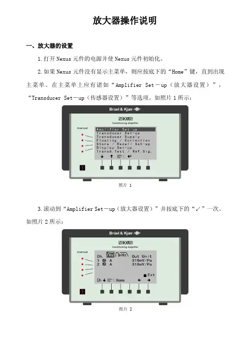
放大器操作说明一、放大器的设置1.打开Nexus 元件的电源并使Nexus 元件初始化。
2.如果Nexus 元件没有显示主菜单,则应按底下的“Home ”键,直到出现主菜单。
在主菜单上应有诸如“Amplifier Set -up (放大器设置)”,“Transducer Set -up (传感器设置)”等选项。
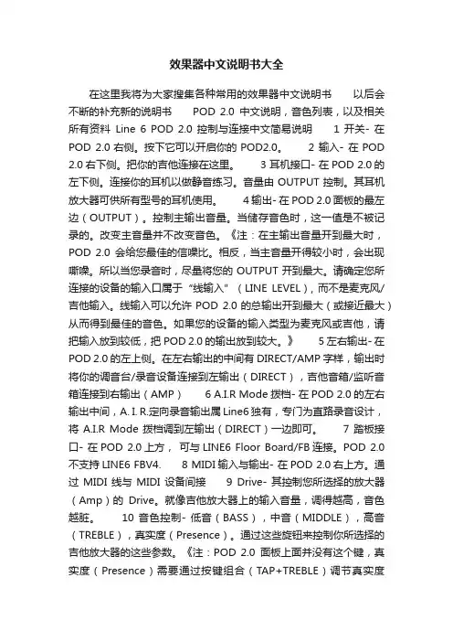
如照片1所示:3.滚动到“Amplifier Set -up (放大器设置)”并按底下的“↙”一次。
如照片2所示:照片 1照片 24.在“Amplifier Set -up (放大器设置)”菜单下,应通过在底下箭头键来滚动到“Hz ”,以确保“Hz ”显示加亮。
一旦“Hz ”显示加亮,则按 “Ch ↓”键。
随后应用“+”和“-”按键来设置Hz (频率)为A 。
一旦通道1设置为A ,则应按 “Ch ↓”键,并对通道2,3和4作同样的工作。
如果是2通道Nexus 元件,那么只需要编程两个通道。
当所有通道设置为A 时,按“Home ”键返回。
如照片3所示:然后,用“→”键移动到“Out (输出)”。
一旦“Out (输出)”被显示加亮,使用“Ch ↓”键和“+”与“-”键把每个通道都设置为316mV/Pa 。
当所有通道都设置为316mV/Pa 后,按“Home ”键返回。
最后回顾一下菜单,确保所有的通道都被分别设置在A 下,“Out ”输出为316 mV/Pa 。
当所有设置项都设置正确后,按“Home ”键返回。
如照片4所示:照片 3滚动到“Transducer Set -up (传感器设置)”下并按底下的“↙”一次。
如照片5所示:(此步可以省略,因为麦克风的灵敏度是自动识别的不用设置)编辑此菜单需要声学传感器的校准数值。
当得到校准数值后,滚动到“Sensitivity (灵敏度)”并按“Ch ↓”键。
如照片6所示:照片 4照片 5随后将处在显示加亮的十进制数值的通道#1。
用“+”与“-”键把此数值设置为对应于此通道/声学传感器的校准/灵敏度数值。
效果器中文说明书大全在这里我将为大家搜集各种常用的效果器中文说明书以后会不断的补充新的说明书POD 2.0中文说明,音色列表,以及相关所有资料Line 6 POD 2.0 控制与连接中文简易说明 1 开关- 在POD 2.0右侧。
按下它可以开启你的POD2.0。
2 输入- 在POD 2.0右下侧。
把你的吉他连接在这里。
3 耳机接口- 在POD 2.0的左下侧。
连接你的耳机以做静音练习。
音量由OUTPUT控制。
其耳机放大器可供所有型号的耳机使用。
4 输出- 在POD 2.0面板的最左边(OUTPUT)。
控制主输出音量。
当储存音色时,这一值是不被记录的。
改变主音量并不改变音色。
《注:在主输出音量开到最大时,POD 2.0会给您最佳的信噪比。
相反,当主音量开得较小时,会出现嘶噪。
所以当您录音时,尽量将您的OUTPUT开到最大。
请确定您所连接的设备的输入口属于“线输入”(LINE LEVEL), 而不是麦克风/吉他输入。
线输入可以允许POD 2.0的总输出开到最大(或接近最大)从而得到最佳的音色。
如果您的设备的输入类型为麦克风或吉他,请把输入放到较低,把POD 2.0的输出放到较大。
》 5 左右输出- 在POD 2.0的左上侧。
在左右输出的中间有DIRECT/AMP字样,输出时将你的调音台/录音设备连接到左输出(DIRECT),吉他音箱/监听音箱连接到右输出(AMP) 6 A.I.R Mode拨档- 在POD 2.0的左右输出中间,A. I. R.定向录音输出属Line6独有,专门为直路录音设计,将A.I.R Mode拨档调到左输出(DIRECT)一边即可。
7 踏板接口- 在POD 2.0上方,可与LINE6 Floor Board/FB连接。
POD 2.0不支持LINE6 FBV4. 8 MIDI输入与输出- 在POD 2.0右上方。
通过MIDI线与MIDI设备间接9 Drive- 其控制您所选择的放大器(Amp)的Drive。
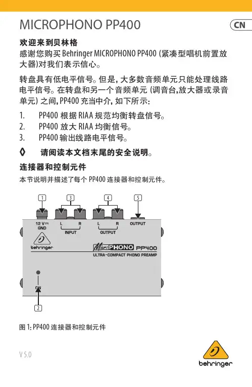
MICROPHONO PP400V 5.0欢迎来到贝林格感谢您购买 Behringer MICROPHONO PP400 (紧凑型唱机前置放大器)对我们表示信心。
转盘具有低电平信号。
但是, 大多数音频单元只能处理线路电平信号。
在转盘和另一个音频单元 (调音台,放大器或录音单元) 之间, PP400 充当中介, 如下所示:1. PP400 根据 RIAA 规范均衡转盘信号。
2. PP400 放大 RIAA 均衡信号。
3. PP400 输出线路电平信号。
◊ 请阅读本文档末尾的安全说明。
连接器和控制元件本节说明并描述了每个 PP400 连接器和控制元件。
图 1: PP400 连接器和控制元件2MICROPHONO PP400(1) 12 伏连接器: 要将电源设备连接到 PP400, 请使用12 V 连接器。
将电源设备连接到电源会自动打开 PP400。
要断开设备与电源的连接, 请拔出电源线插头。
(2) 在 LED: 将设备连接到电源后, ON LED 点亮。
(3) 输入(左和右) 连接器:要将转盘信号发送到 PP400, 您需要 RCA 音频电缆 (立体声)。
使用此电缆连接:• 转盘上的左侧输出到 PP400 上的L(左侧)输入• 转盘上的右侧输出到 PP400 上的R(右侧)输入PP400 可以通过以下连接器之一输出线路电平信号:• RCA ((4)输出 L 和 R )• ¼" TRS ((5)输出)◊ 请勿同时使用两个 PP400 OUTPUT 。
(4) 输出(左和右)连接器: 要使用这些 RCA 连接器, 您需要一条 RCA 音频电缆 (立体声)。
使用此音频电缆连接:• PP400 上的L(左) 输出到放大器, 记录单元或混音器上的左输入。
(在调音台上, 使用 CD 或 TAPE 输入。
)• PP400 上的R(右) 输出到放大器, 录音单元或混音器上的右输入(5) 输出 连接器: 要使用此 ¼" TRS (立体声) 连接器, 您需要音频电缆。

STARLINE SeriesMB1001 GHzAmplifierFor cable operators looking to ensure maximum backwards compatibility and scalability and protect network investments, ARRIS offers solutions that deliver new services with minimal CAPEX, enhance network efficiency, and increase subscriber satisfaction. The ARRIS 1 GHz MB100 Amplifier enables cable operators to increase forward capacity while maintaining current amplifier spacing of existing 750 and 870 MHz systems. The MB100is available as a complete unit for greenfield deployments or as a drop‐in RF module for 1 GHz upgrades to legacy STARLINE MB75 and MB87 amplifiers.PRODUCT OVERVIEWFEATURES•Simplify plant upgrades with modular RF design and 1.2 GHzcapable housing•Improve amplifier reach with optional GaN technology andincreased station tilt•Maintain current amplifier spacing with high output GaAstechnology•Expand return path bandwidth with plug‐in diplex filter supportto 85 MHz•Minimize RF drift over temperature with optional analog orQAM ADUForward PathThe standard MB100 configuration is equipped with second‐generation Enhanced Gallium Arsenide (E‐GaAs) technology with two driven RF outputs, which provides superior distortion performance over standard silicon and competing GaAs technologies. If operators require longer reach, the MB100 can be configured with optional Gallium Nitride (GaN) hybrid technology, which allows for a 3 dB increase in output level over the standard GaAs option.To provide additional system flexibility, easy installation and maintenance, the MB100 is compatible with standard accessories such as attenuators, equalizers, ADUs or QADUs, automotive fuses, and FTEC crowbar circuits. The amplifier maintains output level via an optional plug‐in drive unit. In addition, operators can control level manually, thermally with the TDU (thermal drive unit) accessory, or electronically with the automatic drive unit (ADU). The ADU can support either analog or QAM pilot channels.The MB100 uses modular diplex filters, which operators can change to increase return bandwidth. The following filters are available for use with all US‐style STARLINE RF distribution amplifiers (models BLE, MB/MBV3, BT):•K‐split (5 to 42 MHz/54 to 1003 MHz)•A‐split (5 to 65 MHz/85 to 1003 MHz)•N‐split (5 to 85 MHz/104 to 1003 MHz)Return PathThe MB100comes standard with a high‐gain return amplifier. Operators can select SRE return path equalizers ranging from 0 to 12 dB.Backward CompatibilityOperators can make the MB100 electronics package backward compatible with the 10‐Amp MB*/* housing by installing theMB‐15AII Kit. These kits contain 50 mil gold plated platform assemblies, which make it possible for the amplifier to carry 15 Amperes continuous through its input or output ports.COMPATIBILITYPlatform MB‐550MB‐750D MB‐750SH MB86MB87 Upgrade to MB100No No Yes*Yes*Yes* Requires MB‐15AII KitRELATED PRODUCTSADU/QADU MBV3BLE100BT100SFE/SRE EQ Installation ServicesFlex Max®RF AmplifiersSpecifications –E‐GaAsSpecifications Units Forward ReturnFrequency split1MHz K (54 –1003)A (85 –1003)N (104 –1003)19K (5 –42) A (5 –65) N (5 –85)Flatness 2,19dB±0.75±0.5 Minimum Full Gain 3dB4620 Operation Gain 4dB42NA Manual Bode Slope Control Range 5dB±4NA Noise Figure 6dB98 Standard Slope Reference Frequency MHz1003/550/5435 (flat) Reference Output Level dBmV51/44/37—Operating Interstage Slope7dB14 ±1NA Standard Slope DistortionChannels, Number of NTSC17Composite Triple Beat (CTB) 8,16Cross Modulation (XM) 9,16Composite Second Order(CSO) 8,10,16 Carrier to Intermodulation Noise (CIN)21 Channels, Number of 256 QAMCarrier to Intermodulation Noise (CIN)20,21dBcdBcdBcdBdB7976.568.57165154656807081———Test Point 11dB20 (±1.0 dB)20 (±1.0 dB) Return Loss 12dB14.515 Hum Modulation @ 12A dBc< 60< 60 Hum Modulation @ 15A 12dBc< 60< 65 DC Voltage VDC24Current DC Max. 13mA1600Power Consumption Max.W52AC Input Voltage Range VAC38–90AC Current Draw Max.@ 90 VAC@ 60 VAC@ 38 VAC A0.580.921.45AC Bypass Current (all ports) 14A15Group Delay 15K‐split55.25 to 58.83 MHz nSec52NA Group Delay 15A‐split86.25 to 90.68 MHz nSec28NA Group Delay 19N‐split109.25 to 112.83 MHz 112.25 to 116.68 MHz nSecnSec149NANAOperating Temperature Range °C°F–40 to +60–40 to +140Housing Dimensions, L x W x D InchesMm15.4 x 9.6 x 5.5292 x 244 x 140Weight lbKg156.8Specifications –E‐GaNSpecifications Units Forward ReturnFrequency split1MHz K (54 –1003)A (85 –1003)N (104 –1003)19K (5 –42) A (5 –65) N (5 –85)Flatness 2,19dB±0.75±0.5 Minimum Full Gain 3dB46NA Operation Gain 4dB4220 Manual Bode Slope Control Range 5dB±4NA Noise Figure 6dB98 Ultra Slope Reference Frequency7MHz1003/550/5435 (flat) Reference Output Level dBmV57/48/39—Operating Interstage Slope dB18 ±1NA Ultra Slope DistortionChannels,Number of NTSC17Composite Triple Beat (CTB) 8,16Cross Modulation(XM) 9,16Composite Second Order(CSO) 8,10,16 Carrier to Intermodulation Noise (CIN)21 Channels, Number of 256 QAMCarrier to Intermodulation Noise (CIN)20,21dBcdBcdBcdBdB7970626958154586807081———Standard Slope Reference Frequency 7MHz1003/550/5435 (flat) Reference Output Level dBmV51/44/37—Operating Interstage Slope 6dB14 ±1NA Standard Slope DistortionChannels, Number of NTSC17Composite Triple Beat (CTB) 8,16Cross Modulation (XM) 9,16Composite Second Order(CSO) 8,10,16 Carrier to Intermodulation Noise (CIN)21 Channels, Number of 256 QAMCarrier to Intermodulation Noise (CIN)20,21dBcdBcdBcdBdB7975667166154666807081———Test Point 11dB20 (±1.0 dB)20 (±1.0 dB) Return Loss 12dB14.5 15 Hum Modulation@ 12A dBc< 60<60 Hum Modulation @ 15A 18dBc< 60< 65 DC Voltage VDC24Current DC Max. 13mA1600Power Consumption Max.W52AC Input Voltage Range VAC38–90Specifications –E‐GaN(continued)Specifications Units Forward ReturnAC Current Draw Max.@ 90 VAC@ 60 VAC@ 38 VAC A0.580.921.45AC Bypass Current (all ports) 14A15Group Delay 15K‐split55.25 to 58.83 MHz nSec52NA Group Delay 15A‐split86.25 to 90.68 MHz nSec28NA Group Delay 19N‐split109.25 to 112.83 MHz 112.25 to 116.68 MHz nSecnSec1412NANAOperating temperature range°C°F –40 to +60–40 to +140Housing dimensions, L x W x D inchesmm 15.4 x 9.6 x 5.5 292 x 244 x 140Weight lbkg 15 6.8Notes:1.Operating passband of station. Diplex filters are plugged into the electronic chassis.2.Referenced to the average gain across the passband.3.Minimum full gain at 1003 MHz includes loss of equalizer but Bode slope reserves have not been set. Return gain includes loss of SRE‐*‐4 return equalizer. Measured at Fmaxreturn.4.Includes loss of gain reserves as well as equalizer.5.From midpoint (typical setting is –4 dB at 1003 MHz @ 25 °C). This control should not be used for gain reduction.6.Specified at the housing cable entry facility over temperature and includes the loss of 1 dB for the pre‐stage equalizer. The return noise figure includes the station loss preceding theRF hybrid.7.Amount of slope created and cable equivalence of fixed, plug‐in interstage equalizer.8.Measured with CW carriers and spectrum analyzer over specified temperature range. References the worst‐case channel.*9.Measured with wave analyzer and synchronous, 100% depth modulated channels. References the worst‐case channels over specified temperature range.*10.Refers only to beat clusters that fall 0.75 MHz and 1.25 MHz above the subject picture carrier.11.Test points should be used with GFAL adapter.12.Match measurement at the station input and output, cable‐entry facilities, at the specified passband for operational gain.13.Current draw at 24 VDC.14.Stated in RMS continuous.15.Specified for standard NTSC video, where delay is the delta from picture carrier to 3.58 MHz color subcarrier. Reverse delay is in a 1.5 MHz bandwidth.16.Worst‐case over temperature in a cascade.17.NTSC 79 Channel forward, 75 QAM carriers –6dB relative to analog CW carriers. 6 Channel return.18.Specification is 55 from 5 to 10MHz at 15A.19.For N‐split (5–85/104–1003MHz) roll‐off from 105 MHz to 102 MHz < 1.0 dB. Group delay from 103.25 MHz to 105.25 MHz is < 22 ns.20.154 QAM carriers 54‐1002 MHz. Carriers are ‐6dB relative to virtual analog levels.21.Room temperature performance.* Specifications are compliant with the test methods as stated in NCTA Recommended Practices for Measurements on Cable TelevisionNote: Specifications are subject to change without notice.Copyright Statement: ©ARRIS Enterprises, Inc. 2015 All rights reserved. No part of this publication may be reproduced in any form or by any means or used to make any derivative work (such as translation, transformation, or adaptation) without written permission from ARRIS Enterprises, Inc. (“ARRIS”). ARRIS reserves the right to revise this publication and to make changes in content from time to time without obligation on the part of ARRIS to provide notification of such revision or change. ARRIS and the ARRIS logo are all registered trademarks of ARRIS Enterprises, Inc. Other trademarks and trade names may be used in this document to refer to either the entities claiming the marks and the names of their products. ARRIS disclaims proprietary interest in the marks and names of others. The capabilities, system requirements and/or compatibility with third ‐party products described herein are subject to change without notice.MB100_DS_27OCT141 GHz MB Ordering GuideRequired AccessoriesPart NumberModelDescription535723‐001‐00531124‐001 to ‐022531161‐001 to ‐010SFE ‐100‐0SFE ‐100‐1 to ‐22SCS ‐1 to SCS ‐10Forward 1003 MHz equalizer (0 dB) ‐or ‐Forward 1003 MHz equalizer (values 1 to 22 dB 1n 1 dB steps)‐or ‐Cable simulator (values 1 to 10 dB in 1 dB steps)531163‐XXX ‐00SRE ‐*‐*Return equalizer, 5‐42 MHz (K ‐split), 5‐65 (A ‐split), 5‐85 (N ‐split), values 0 to 12 dB 1n 2 dB steps 531186‐XXX ‐00JXP ‐*BPlug ‐in attenuator/pad (values 0 to 26 dB in 1 dB steps)Optional AccessoriesPart NumberModelDescription531230‐001‐00SP100Splitter (1 GHz) to activate third output ‐or ‐531230‐002‐00DC100/8Directional coupler (1GHz)to activate third output (8dB)531230‐003‐00DC100/10Directional coupler (1GHz)to activate third output(10dB)531230‐004‐00DC100/12Directional coupler (1GHz)to activate third output (12dB)594742‐002‐00QADU ‐609.00/S ‐R 609 MHz QAM Automatic Drive Unit 594742‐001‐00QADU ‐711.00/S ‐R 711 MHz QAM Automatic Drive Unit 531236‐003‐00ADU ‐499.25/S ‐R 499.25MHz Automatic Drive Unit 531344‐002‐00MB ‐15AII ‐KIT15 Amp kit to upgrade 10 Amp platforms(rev 10-2014) Customer CareContact Customer Care for product information and sales:•United States: 866‐36‐ARRIS •International: +1‐678‐473‐5656Notes:1.Not all combinations in the ordering guide are available. This is a guide only.2.FTECs are included in all models as standard.。
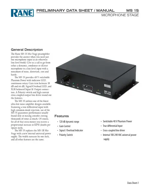
Data Sheet-1MS 1SMICROPHONE STAGEGeneral DescriptionThe Rane MS 1S Mic Stage preamplifier provides the answer when you need just one microphone input in an otherwise line-level world. Give us a call to go from either a dynamic, condenser or electret microphone to a line-level input with a minimum of noise, distortion, cost and hassle.The MS 1S provides 48 V switchable Phantom Power with indicator LED, continuous rotary Gain trim between 18 dB and 66 dB, Signal/Overload LED, and XLR balanced Input & Output connec-tors. A Polarity switch and high-current cross-coupled output line driver round out the features.The MS 1S utilizes one of the finest ultra low noise amplifier designs available. Featuring a true differential input with high common-mode rejection, use of the MS 1S guarantees performance usually found only in mixing consoles costing thousands of times as much. Of course, for all of that extra money you receive a proportional increase in KPSI (knobs per square inch).The MS 1S replaces the MS 1B Mic Stage with a new internal universal power supply. The width increases by one inch, and all other features are the same.Features• 120 dB dynamic range • Gain Control• Signal / Overload Indicator • Polarity SwitchPRELIMINARY DAT A SHEET / MANUAL • Switchable 48 V Phantom Power • True differential Input • Cross-coupled line driver• Internal 100-240 VAC universal powersupplyMS 1S MICROPHONE STAGEFeatures and SpecificationsParameter Specification Limit Units Conditions/CommentsInput Impedance10k1%ΩBalanced 5k + 5kGain Range18 to 66typ.dBPhantom Power+484%V10 mA max...........Impedance 6.81k1%ΩEach leg..........Load Regulation0.1typ.%0 to 14 mA..........RMS CM Noise.003typ.%% of Vout (10 Hz to 10 kHz)Max. Input Level+10 / -32min.dBu Gain 18 / 60, balanced outputEquivalent Input Noise-128typ.dBu20 kHz BW, Rs=150 Ω, Gain = 60 dB Signal to Noise Ratio96typ.dB20 kHz BW, Rs=150 Ω, Gain = 18 dB, re 4 dBu Dynamic Range120 / 95typ.dB Gain 18 / 66CMRR80typ.dB Rs=150 Ω, 120 Hz, Gain = 60 dB Frequency Response..........Gain 60 dB45 to 200k typ.Hz+0, -3dB..........Gain 18 dB30 to 200k typ.Hz+0, -3dbTHD+Noise (gain 60 dB).007 (Output=+20 dBu)typ.%55 Hz to 20 kHz, 20 kHz BW, Rl=10 kΩTHD+Noise (gain 18 dB).001 (Output=+20 dBu)typ.%50 Hz to 20 kHz, 20 kHz BW, Rl=10 kΩLine Driver Active Cross-coupled Gain 5.2 / 6 dB typ. unbalanced / balanced Max. Output Level+22 / +27min.dBu Unbalanced / Balanced, 2 kΩ loadOutput Impedance501%ΩEach LegSignal Indicator 2 / 8typ.dBu Unbalanced / Balanced output, Green LED Overload Indicator14 / 20typ.dBu Unbalanced / Balanced output, Amber LED Output Cable Length1000 feet / 300 meters typ.Belden 8451 or equivalentUnit: Agency Listing UL/cUL/CE PendingMaximum Power3WUniversal Line Voltage100-240VAC50/60 HzPower Cord C5 cord to C6 inlet IEC 60320-1Unit Size 1.64"H x 6.8"W x 4.26"D(4.2 cm x 17.3 cm x 10.8 cm) ..........Weight 1 lb 1 oz(0.5 kg)Shipping Size 3.6"H x 11.75"W x 7.2"D(9.5 cm x 30 cm x 18 cm) ..........Weight 4 lb(1.8 kg)Data Sheet-2Data Sheet-3MS 1SMICROPHONE STAGEBlock DiagramApplication InformationUses and applications for the MS 1S should be obvious. But then again, it’s obvious to us our taxes are too high and nothing is being done about that. With this in mind, perhaps a few words on us-ing the MS 1S might not be wasted.BALANCED USEThe MS 1S provides a true cross-coupled balanced output. This is equivalent to an electronic simulation of a transformer output. Rane follows the AES standard of pin 2 = hot.When running a long cable back to the mixer, run a line-level balanced line rather than a mic-level line. The compact MS 1S can mount closer to the micro-phone, provide a local volume control (or not, just pull the knob off), while the stronger signal minimizes RF and hum irritations.UNBALANCED USEBalanced use is recommended to mini-mize noise. Unbalanced lines are usually quiet under 10 feet (3 meters), but longer runs will introduce the hum and interfer-ence you are trying to avoid. When you must drive an unbalanced device with the MS 1S's balanced output, keep the cable short, and connect pin 2 to the “+” or “hot” lead, and tie pin 3 and ground together at the shield .MIXINGThe MS 1S is designed to fill the need for adding a microphone channel to line-level mixers, such as the Rane SM 26S or SM 82S. Many installations using either of these products invariably wind up with one unused input that would do the job perfectly if only it could operate at mic-level. In rides the MS 1S to the rescue.MIC 12-60 dBDIGITAL RECORDING AND SAMPLING Another handy use for the MS 1S is in recording applications. Many popular products do not have a high enough qual-ity mic preamp to suit the resolution of the digital processing electronics. Such irony. Using the ultra low noise MS 1S to bring the mic inputs up to extremely high quality line-level is an easy and affordable solution for this dilemma. No garbage in; no garbage out. Clippity-clop; clippity-clop.MICROPHONE TYPESThe available gain and large input range of the MS 1S allows the use of virtually any type of microphone. True 48V phantom power guarantees the MS 1S works with every microphone. The better the mic, the better the MS 1S sounds.Ah, the sound of the thundering hoofs is deafening.Data Sheet-4MS 1SMICROPHONE STAGEAll features & specifications subject to change without notice. DOC 104514©Rane Corporation 10802 47th Ave. W., Mukilteo WA 98275-5098 USA TEL 425-355-6000 FAX 425-347-7757 WEB Architectural SpecificationsThe microphone preamplifier shall be a single channel stand-alone unit with a removable IEC power cord. The unit shall accept voltages from 100 to 240 VAC. The input and output shall be fitted with XLR connectors. A polarity inverting switch shall be included. Phantom power of no less than 48 volts shall be provided in compliance with IEC 60268-15 and be controlled by a slide switch with an LED indicator. A gain control shall be provided with 18-66 dB adjustment range. Power, system signal and overload indicators shall be provided. High current cross-coupled active output line driver shall be standard, as well as input RFI filter protection.The unit shall be a Rane MS 1S Micro-phone Stage.Dimensions。

1 用户使用手册
前置扩音器011(型号)
柏林之声
耳边的艺术
高端产品,德国制造
柏林之声音响设备有限公司.柏林 kolonnens街 30号.邮编10829 电话+49/30/787968-0 传真+49/30/787968-68 网址
www.burmester.de
2
尊敬的音响发烧友,
感谢您选择此款柏林之声音响配置设备。
我们由衷的感激您对我们(产品)的
信任。
您选择了一款高保真,高制作工艺,高技术创新,以及(在接配操作上)具有
很强灵活性的前置扩音器。
我们强烈建议您完整在首次安装调试011号设备前完整的阅读此操作手册。
它
会让您更好的机器的效果发挥到极致。
如还有问题,请向销售商或我们(制造商)直接联系。
(预祝)您享受(视)听新感觉。
柏林之声团队
6
7
9 (其他)一般操作指令
设备技术标准
耗能关闭(但连接):6瓦
待机:6瓦
打开:25瓦
线增益低:12分贝
高:15分贝(当Vol=60)
大小尺寸(宽x高x深)482x95x345毫米
重量9.6千克
注意尺寸不包括接线所需要的空间。
1DSP 数字前级放大器AS-V1整机特点:■ 高质量的数字效果器,尽显专业水平;■ 音乐信号激励,增强音乐的动感,更有身临其境的感觉; ■ 话筒输入三段均衡,中频扫描; ■ 全平衡话筒输入,抗干扰能力更强; ■ 话筒音色调整;■ 重低音输出,并带扫频功能; ■ 多功能遥控,可外接专用功能控制器。
前面板控制:1.话筒输入插口MIC ,MIC2,MIC3为全平衡6.3mm 标准输入插口。
2.话筒输入增益控制调节对应的电位器,可分别控制MIC1,MIC2,MIC3的输入增益。
3.话筒EQ低频音调:调节该电位器,可改变话筒低频的提升/衰减量,变化量为±15dB 。
中频音调:调节该电位器,可改变话筒中频的提升/衰减量,变化量为±15dB 。
中频扫描:调节该电位器,可改变中频扫描的频率,频率范围250HZ-6KHZ 。
高频音调:调节该电位器,可改变话筒高频的提升/衰减量,变化量为±15dB 。
4.低通滤波器(DSP )显示部分低通滤波器频率范围为8KHZ~18KHZ 连续可调。
5,12. DSP 效果上下滚动按键 内含55种常用OK 效果 6.变调处理按下对应的开关,可对音乐信号进行降调,原调,升调处理。
7. 主音量声象控制:调节该电位器,可将信号以不同量分配到左、右声道上。
主音量高频音调:调节该电位器,可改变主音量高频的提升/衰减量,变化量为±15dB 。
主音量低频音调:调节该电位器,可改变主音量低频的提升/衰减量,变化量为±15dB 。
8.MIC 输出音量控制调节该电位器,可改变话筒输出信号大小。
9.DSP 效果输出音量控制调节该电位器,可改变DSP 效果输出信号大小。
10.主音量输出控制调节该电位器,可改变主音量输出信号大小。
11.电源开关压下电源开关,电源指示灯“ON”点亮,整机进入工作状态。
后面板控制:1.电源输入与市电进行连接,为整机提供电源,请注意市电是否与本机的工作电源相符。
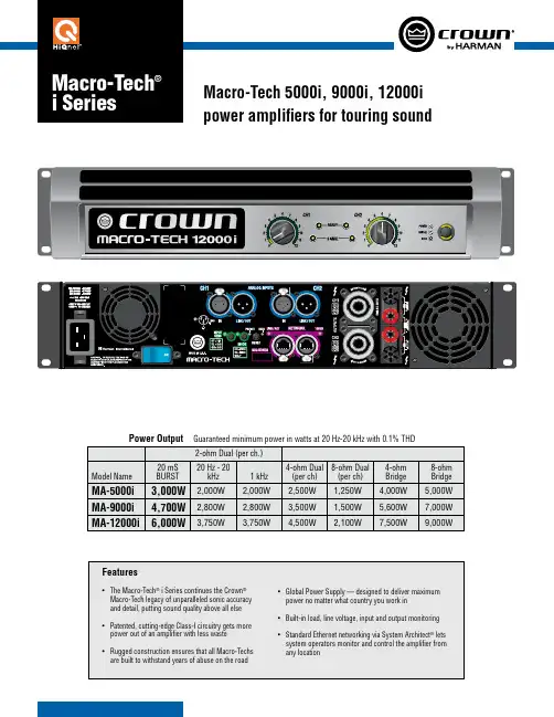
Guaranteed minimum power in watts at 20 Hz-20 kHz with 0.1% THDCrown International 1718 W. Mishawaka Rd.Elkhart, IN 46517-9439 TEL: 574-294-8200 FAX: 574-294-8FAXCustomer Service: 800-342-6939 or 574-294-8200. 5/09 140535-4SpecificationsPerformanceFrequency Response (at 1 watt, 20 Hz - 20 kHz into 8 ohms): ±0.25 dB.Signal to Noise Ratio (below rated full-bandwidth power, A-weighted): > 112 dB.Total Harmonic Distortion (THD) (at 2 watts into 8 ohms): < 0.1%.Total Harmonic Distortion (THD) Plus Noise (at full rated power): < 0.1%, 20 Hz to 20 kHz.Intermodulation Distortion (IMD) (60 Hz and 7 kHz at 4:1, from full rated output to –30 dB): < 0.35%.Damping Factor (20 Hz to 100 Hz at 8 ohms): > 5000.Crosstalk (below rated power, 20 Hz to 1 kHz): > 80 dB.Common Mode Rejection (CMR) (20 Hz to 1 kHz): >70 dB typical.DC Output Offset (shorted input): < ± 3 mV.Input Impedance (nominal): 20 kilohms balanced, 10 kilohms unbalanced.Maximum Input Level: +20 dBu work: Onboard HiQnet™, compatible with standard 100 Mb Ethernet hardware.Load Impedance: (Note: Safe with all types of loads)Stereo: 1/2/4/8/16 ohms. Bridge Mono: 2/4/8 ohms.Input Sensitivity (referenced to 8 ohm rated output): 1.4V, 32 dB gain, and 26 dB gain.Voltage Gain (referenced to 8 ohm rated output): MA-5000i: 37.1 dB to 22.2 dB MA-9000i: 37.9 dB to 23.0 dB MA-12000i: 39.3 dB to 24.5 dBRequired AC Mains: Universal AC input, 100-240VAC (±10%), 50/60 Hz. Maximum AC mains voltage 264VAC.AC Line Connector: Five cordsets supplied with amplifier (USA, UK, European, Australia, India).Front Panel Controls and IndicatorsBridge Mode Indicator: Amber LED illuminates when the amplifier is set to Bridge-Mono mode. Ready Indicator: Green LED, one per channel.On (bright): Ready.On (dim): Onset of compression. Off: Thermal protection.Signal Indicators: One green LED per channel.Solid green: Input signal is above –40 dBu.Bright green: Channel’s output signal has reached the onset of audible clipping.Power Indicator: Blue LED indicates amplifier has been turned on and AC power is available. TheLED will flash when the AC line voltage is 10% above or below the nominal rated value.Data Indicator: Yellow LED on front panel indi-cates network data activity. Data indicator flashes only when the amplifier is polled for data, or is polled to see whether it is onlinePower Switch: Push-on/push-off switch with built-in green AC mains present indicator.Volume Control: Precision detented attenuator with 31 steps, press-and-hold mute function.Volume Control LED Ring: A ring of green LEDs around each volume control show the position of the control. Entire ring flashes when channel is muted. Can be converted to be a level meter.Back Panel Controls, Indicators and ConnectorsPower Cord Connector: Detachable 20 amp IEC inlet. Cord locks with supplied cord retention clip. Voltage range is indicated above IEC inlet.Reset Switch/Circuit Breaker: If the current draw of the amplifier exceeds safe limits, this breaker automatically disconnects the power supply from the AC mains. The switch resets the circuit breaker.Output Connectors: Two high-current, 50A Neu-trik ® Speakon ® NL4MLP (mates with NL4FC or NL4), one per channel. Ch 1 Speakon ® is wired with Ch 1 and Ch 2 outputs for use with single 4-conductor cable. Two pairs of high-current, 60A color-coded 5-way binding posts (for banana plugs, spade lugs or bare wire).Analog Input Connectors: A 3-pin female XLR connector for each channel.Analog Loop Thru Connectors: Two male XLR passive analog loop through.Mode Switch/Indicator: Sets amplifier to Stereo, Bridge, or Input Y mode. OFF=Stereo, YEL=Bridge, GRN=Y.Network Connectors: This Neutrik ® EtherCon ® connector accepts an RJ-45 connector forHiQnet™ networking. Next to the connector is a yellow LINK ACT indicator that shows network activity, and a green 100Mb indicator that shows a 100Mb network connection.Data Indicator: Yellow LED on back panel indi-cates network data activity. Data indicator flashes only when the amplifier is polled for data, or is polled to see whether it is online.Preset Indicator: Green/yellow LED flashes to signal the number of the current preset. LED is green if current preset is active, or is yellow if cur-rent preset is modified.Input Sensitivity Switch: Three-position switch providing 1.4V, 32 dB, and 26 dB settings for both channels.Firmware/SoftwareFirmware can be downloaded at .Software features: User Presets, Clip EventMonitor, Input Signal Level Monitor, Output Signal Level Monitor, Thermal Headroom Level Monitor, Power/Standby Control, Signal Mute, Polarity Inverter, Input Signal Fader, Amplifier Information, User and Channel Labels, Amplifier Mode, Ampli-fier Output Mode, Line Voltage Monitor, Error Reporting, Auto Standby, Input Signal Compres-sor/Limiter, Peak Voltage Limiter, Average Power Limiter, Clip Eliminator, Thermal Limiter, Limiter Tie, Load Supervision.ConstructionCooling: Dual-zone, microprocessor controlled, continuously variable speed fans, front-to-back airflow.Front Panel: Cast aluminum with integrated handles.Dimensions: 19 in. (48.3 cm) W x 3.5 in. (8.9 cm) H x 16.2 in. (41.1 cm) D.Weight: 28 lbs (12.7 kg) net, 36 lbs (16.3 kg) shipping.Protection: Amplifier is protected against reactive loads, faults and shorts. If one channel experi-ences a catastrophic failure, the entire amplifier will shut down.Included Accessories: Rear rack ears, rackscrews, operation manual, power cords, foam air filter.Note: All measurements apply to units in Stereo mode with 8-ohm loads and rated input sensitivity unless oth-erwise specified.Specifications subject to change without prior notice. Latest information available at .Crown, Macro-Tech and Crown Audio are registeredtrademarks. HiQnet is a trademark of Harman International Industries, Inc. Other trademarks are the property of their respective owners. Printed in U.S.A.© 2008 Crown Audio ® Inc。
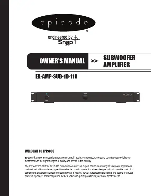
EA-AMP-SUB-1D-110WELCOME TO EPISODEEpisode® is one of the most highly regarded brands in audio available today. We stand committed to providing our customers with the highest degree of quality and service in the industry.The Episode® EA-AMP-SUB-1D-110 Subwoofer Amplifier is a superb choice for a variety of subwoofer applications and work well with almost every type of home theater or audio system. It has been designed with advanced technologicalcomponents that produce astounding sound effects in movies, as well as recreating the heights and depths of all typesof music. Episode® amplifiers provide the best value and quality possible for your home theater needs.pg.2EA-AMP-SUB-1D-110 Installation and Users ManualWARNING : To reduce the risk of fire or electric shock, do not expose this apparatus in or near rain or moisture.1. Read and keep these instructions for future reference.2. Do not use this apparatus near water.3. Clean only with a dry cloth.4. Do not block any ventilation openings. Install according to manufacturer’s instructions.5. Do not install near any heat sources such as radiators, heat registers, stoves or other apparatus(including amplifiers) that produce heat.6. Do not override the safety purpose of the polarized or grounding-type plug. A polarized plug has two blades -one wider than the other. A grounding type plug has two blades and a third grounding prong. The wide bladeor the third prong is provided for your safety. If the provided plug does not fit into your outlet, consult anelectrician for replacement of the obsolete outlet.7. Protect the power cord from being walked on or pinched particularly at plug, convenience receptacles, andthe point where it exits from the apparatus.8. Only use attachments/accessories specified by the manufacturer.9. Use only with a cart, stand, tripod, bracket or table specified by the manufacturer,or sold with the apparatus. When a cart is used, use caution when moving thecart/apparatus combination to avoid injury from tip-over.10. Unplug this apparatus during lightning storms or when unused for long periods of time.11. Refer all servicing to qualified service personnel. Servicing is required when the apparatus has been damagedin any way, such as when the power-supply cord or plug is damaged, liquid has been spilled or objects have fallen into the apparatus, the apparatus has been exposed to rain or moisture, does not operate normally, or hasbeen dropped.12. To completely disconnect this equipment from the AC mains, disconnect the power supply cord plug fromthe AC receptacle13. This is CLASS II apparatus with double insulation, and no protective earth provided.The lightning flash with arrowhead symbol, within an equilateral triangle, is intended to alert the user to the presence of uninsulated dangerous voltage within the product’s enclosure that may be of sufficient magnitude to constitute a risk of electric shock to persons. The exclamation point within an equilateral triangle is intended to alert the user to the presence of important operatingand maintenance (servicing) instructions in the literatureaccompanying the appliance.IMPORTANT SAFETY INSTRUCTIONS© 2011 Episode EA-AMP-SUB-1D-110 Installation and Users Manualpg.3FEATURES1. Power Switch a. RED – Off/Standby b. Blue – On/Operating2. Output Volume Control1. AUDIO INPUTS a. Connect the Right Female RCA input to an LFE output connection on a receiver or pre-amp processor.b. Connect the Left and Right Female RCA input to the Left and Right front output. connections on a receiver or pre-amp processor.NOTE: Both inputs have been calibrated to the same sensitivity level. When using stereo pre-amp outputs, both connections should beused to maintain proper input gain.2. 12V Trigger In a. Connect the 12V trigger output of the AV receiver to turn amp on when a 12V signal is received. When using a 12V trigger, the Power Mode settings do not apply. See System Connections for more information.3. POWER MODES a. ON – Always On b. Signal Sense – On, triggered via signal sense; when signal is off, amp will stay on for approximately 15 to 20 minutes.4. CROSS-OVER Crossover frequency setting of the Low Pass Filter can be adjusted from 40 to 140 Hz.NOTE: When using the LFE input, set to LFE so the preamplifier or receiver can control the crossover frequency.5. PHASE The phase of the subwoofer can be adjusted to fine tune the alignment of subwoofer signals and with those from the main speakers. Adjust the phase, listening for an increase in mid bass in the crossover region.6. SPEAKER OUTPUTS a. Connect the speaker wires to the Binding Posts. NOTE: Red is Positive and Black is Negative. Bridged output, do not ground. b. Use Bare Speaker Wire, Spade Lugs, or Banana Plugs to terminate the speaker wire.7. AC POWER a. Input voltage setting selects the appropriate 115V or 230V setting. b. IEC Power Cordpg.4EA-AMP-SUB-1D-110 Installation and Users ManualINSTALLATION – FIRST STEPSPOSITIONING YOUR EPISODE AMPLIFIER Episode amplifiers are designed to help deliver a great audio experience that makes your music come alive for years to come. However, where you place the amplifier can have a large effect on the performance that you receive and the life of the unit.• Be sure that the unit is in a well-ventilated area that provides adequate cooling.• Do not block the cooling vents located on both sides of the unit.• Do not place the unit on carpeting or any similar material.• Do not install the unit near a source of heat, or in an extremely humid or wet location.• If your installation lacks good air flow (such as solid cabinet doors or wall-mounted racks), it may be necessary tocreate ventilation to allow outside air into the space.• Allow a minimum of 5” of free air space above the unit.• Allow a minimum of 3” of free air space on either side of the unit. (Does not apply to rack mounting)VENTILATIONDo not block ventilation holes, or impede air flow by placing objects on oraround the amplifier. Do not place the amplifier on carpeting or any similarmaterial. Do not install the amplifier near a source of heat, or in anextremely humid or wet location.RACKMOUNT INSTALLATION1. Remove the amplifier’s four feet from the bottom of the chassis.2. Attach the included rack-mount ears to the front sides of the amplifier chassis.3. Securely mount the amplifier into the 19” equipment rack. The amplifier willoccupy 1U of rack space.4. Even though the amplifier produces very little heat, it is always wise to leaveventilation between components.When placing on a cabinet shelf, position the unit with all feet resting on a solid level surface.© 2011 EpisodeEA-AMP-SUB-1D-110 Installation and Users Manualpg.5SYSTEM CONNECTIONSCAUTION: All connections and switching must be done with the amplifier’s power switch positioned to ‘Off’ (LED will be RED). Connect the power cord last to be sure that the amplifier is off during all of your connections and set up.For line level connections, use high-quality RCA cables that feature low impedance, shielding and high-quality connectors.SPEAKER OUTPUTSUse 14-18 gauge stranded two-conductor loudspeaker wire for all high level connections. At each loudspeaker-level connection, ensure that at least 2 inches of each conductor are separated. Strip away 1/4 inch of insulation from each conductor. Connect the appropriate conductor to each screw terminal, observing correct polarity.pg.6EA-AMP-SUB-1D-110 Installation and Users Manual12V DC Trigger The EA-AMP-SUB-1D-110 is equipped with a 12V trigger input to turn the amplifier off, saving power consumption when not in use. When this input receives a 12V signal, the amplifier will turn ON and will turn OFF when the signal goes away.• Connect the 12V trigger output of the AV receiver to the 12V trigger input of the EA-AMP-SUB-1D-110using a high-quality 3.5mm (1/8”) mono cable.FINE TUNINGAfter making all the connections and calibrating the loudspeakers, set up your Episode subwoofer using the following steps:NOTE: When using an AV receiver and the LFE input, set the subwoofer calibration level to the factory setting1. Ensure that the subwoofer is plugged in.2. Set the following controls and switches to positions that will enable tuning for maximum performance.a. VOLUME knob set to 50%, or 12 o’clockb. CROSSOVER knob set to 120 Hz or 12 o’clockc. PHASE switch set to 0º3. During initial setup, it may be helpful to set the MODE switch to the ‘ON’ position. Once calibration is complete, switch it to ‘AUTO’ to enable the automatic power-saving mode.4. Play a movie scene or music track and set the system volume to an average level. Listen to the bass level from your favorite listening position. Adjust the VOLUME control as desired.5. If deeper bass is desired, adjust the CROSSOVER control toward the lower frequencies. Experiment with different frequency settings until you find one that sounds best.NOTE: When using the LFE input, set to LFE and make any crossover adjustments in the preamplifier or receiver crossover settings.6. Continue listening to your favorite music and movie sources using the settings chosen for volume and crossover.Now, try experimenting with the PHASE switch until you find the best setting for the installation. Depending on your subwoofer’s placement, the bass may sound louder or deeper when the phase has been optimized. In some cases, adjusting phase will make no discernible difference.• If the receiver does not have a 12V trigger output, using a 12V power supply plugged into a switched outlet on the receiver provides the same functionality.12V DC Pinout(Tip)© 2011 Episode EA-AMP-SUB-1D-110 Installation and Users Manual pg.7Continuous Power Output 68 watts RMS at 8 ohms110 watts RMS at 4 ohmsInput Sensitivity 195 mv for full output, 110 watts, with level control set to max.Frequency Response 35 - 200 HzDistortion .10% THD+N 1W/2W 100 HzAuto On Sensitivity 3.5 mvExternal Trigger Voltage 9.5 V - 20 VDimensions 16.9˝ W (18.9˝ including rack mounts)1.75˝ H (1.9˝ including feet)8.5˝ D (knob to rear chassis) 9.3” D (knob to rear speaker connector)Weight 19.7 lbs.Certification ETL Listed and tested under UL/EN60065 for US and CanadaNo audio output • Power cable to the amplifier is incorrectly connected or pluggedinto an outlet that does not have power. Check connections andverify power at the outlet.• Audio cable to the source component is not connected properly,connected to output or the cable is defective. Check connectionsor replace cable with one that has been verified as good.• Amplifier is in standby mode, and needs to be turned on “BLUE LED”.• Check the connections of the speaker wire at both the speaker and amplifier.• The level adjustment is turned down. Turn it to the right slowly toraise the volume.Hum or buzzing sound is heard • Check RCA input cables by removing them one at a time (poweringdown the amplifier before disconnecting) and verify connections.Amplifier will not turn on • The amplifier must be plugged into a live outlet.• The Power Switch on the front panel must be on.• The Power Mode switch may be set to the wrong mode for your system.SPECIFICATIONSTROUBLE SHOOTINGThis amplifier is designed to function trouble-free. Most problems that occur are due to simple issues.If you have trouble, check the list of simple fixes below. If the problem persists, contact your authorizedEpisode dealer or Episode technical support at 866-838-5052.WARRANTY 2-Year Limited WarrantyEpisode™ Amplifier Products have a 2-Year Limited Warranty. This warranty includes parts and labor repairs on all components found to be defective in material or workmanship under normal conditions of use. This warranty shall not apply to products which have been abused, modified or disassembled. Products to be repaired under this warrantymust be returned to the SnapAV or a designated service center with prior notification and an assigned return authorization number (RA).111004 © 2011 Episode。
柏林之声音响使用说明嘿,朋友们,今天咱们聊聊“柏林之声音响”的使用方法。
这个声音响,可不是一般的声音响,它就像你生活中的小精灵,随时准备给你带来音乐的盛宴和清晨的第一缕阳光。
先别急,慢慢来,让我带你们一起探索这玩意儿到底怎么玩。
拿到手的第一步,别忘了充电。
听起来简单吧,但我跟你说,没电就像老虎没有爪子,啥也干不了。
所以,找到那个充电器,插上去,等它充个满。
就像你早上要喝杯咖啡一样,充电是个必须的仪式,没电的声音响可比没咖啡的早晨难受多了。
充好电后,别急着急着打开它,先给它点时间,让它也缓一缓,毕竟好东西都得慢慢来。
打开它的电源。
哎呀,这一刻可真重要,按下去的时候就像打开了新世界的大门,随之而来的音效简直能让人热泪盈眶。
你会看到一个小指示灯亮起,那就是它在跟你打招呼。
哦,真是太有情感了,不是吗?现在,想听什么就得考虑一下了,给你一个推荐,早上来一首《小幸运》,瞬间清醒,感觉整个人都被阳光包围了。
连接蓝牙。
现在是个科技的时代,连声音响都得跟上潮流。
打开你的手机,进入设置,找到蓝牙,点击连接。
这一步,简单得就像穿鞋子。
别紧张,有时候连接会需要一点耐心,就像你等着煮水一样。
连接成功后,嘿,恭喜你,你的声音响已经准备好为你服务了!可以尽情享受音乐的魅力,随心所欲播放你的播放列表。
你想唱就唱,想跳就跳,家里那一小块地方瞬间变成了你的舞台。
听歌的时候,调节音量也是个技术活。
记得哦,调音量可不能像开玩笑,太大了邻居会来敲门,太小了自己听不见。
找到合适的音量,就像在调制一杯鸡尾酒,得有个好比例,才能让人耳朵享受。
然后,试着用它放一些经典老歌,听听那熟悉的旋律,真的是让人怀念。
每个音符都像是时间的胶囊,把你带回到那些无忧无虑的日子。
哦,对了,有时候还会有个小功能,叫做“音效调节”。
根据你的心情来选择不同的模式。
有时候想要嗨起来,可以选择“摇滚模式”,简直要让整个房间都跟着节奏震动。
又或者,有时候想静静,那就选个“轻音乐”,让一切都变得温柔细腻。
FOCAL SW1000BE 中文说明书
型式:主动式超低音喇叭
单元組成:11“:”W“三文治低音
使用单体:11吋W振膜低音单体×1
內建扩大机:BASH 350瓦(最大450瓦)
頻率响应:29Hz-150Hz
重量:25 kg
尺寸:430×422×402mm(高×宽×深)
FOCAL SW 1000 Be低音炮是Electra Be低音炮经过重新设计的版本,以确保与Sopra系列中其他扬声器兼容。
它配备一个13(33cm) W椎体音响驱动(高刚性,即使在高音量下也不易失真),一台高功率600WRMSBASH®放大器以及一个前层流倒相管(没有动态低音压缩)。
24位数字处理器(DSP)提供了一个大的控制面板,其中带有各种设定,让低音炮能适应各种听音室。
SW1000Be性能极高,低音截止频率为18 Hz,同时SPL为118dB。
可连接多个SW1000Be低音炮。
DCD-A110 SUPER AUDIO CD PLAYER 操作说明书附件4安装电池5遥控器的操作范围5部件名称与功能6前面板6显示屏8后面板9遥控器10连接方法连接放大器14连接带有数字音频输入端子的设备15连接定时器设备16连接电源线17播放基本操作19开启电源19切换电源至待机19切换显示屏亮度20切换纯直入模式20设置超级音频CD的最优先播放层21播放CD/超级音频CD22播放CD/超级音频CD22以特定顺序播放曲目(编程播放)24播放DATA CD和DATA DVD26播放文件27使用定时器播放功能29设置设置自动待机模式30提示提示32故障诊断33电源无法开启/电源自动关闭34使用遥控器无法执行操作35本机显示屏不显示内容35不发出声音36声音中断或出现噪音36无法播放光碟37保修和修理38附录可播放的媒体39光碟39音乐文件的播放顺序41关于光碟和文件42使用媒体的注意事项43装入光碟43关于媒体的使用44清洁光碟44术语解释45规格48索引51感谢您购买本Denon产品。
为了确保正确操作,请在使用本品前认真阅读本操作说明书。
阅读之后,请务必妥善保管以备将来参考。
附件请检查并确认本产品附带下列部件。
安装电池12按照指示将两节电池正确插入电池匣内。
3装上后盖。
注0为防止损坏电池或电池漏液 :0请勿将新旧电池混合使用。
0请勿使用两种不同类型的电池。
0如果打算长时间不使用遥控器,请取出遥控器中的电池。
0如果电池漏液,须仔细地擦去电池匣内的漏液,然后装入新电池。
遥控器的操作范围操作遥控器时应将其指向遥控感应窗。
部件名称与功能前面板有关详情,请参阅下一页。
A 电源操作(X )键开启/关闭电源。
(v 第19页)B 电源指示灯根据电源状态,指示灯如下所示 :0通电: 白色0待机 : 熄灭0电源关闭 : 熄灭C Ultra AL32 Processing 指示灯当本机用于以下途径时, Ultra AL32 Processing 将被激活,该指示灯点亮。
XTZ SUB AMP1低音放大器用户手册© 2009XTZ AB , 重要防护措施1.阅读防护措施—在使用设备前,请仔细阅读用户手册中所有相关警告信息。
2.遵循使用说明—操作使用本产品时,请遵循用户手册中相关说明,请勿违反。
3.远离灰尘与潮湿—不可将设备放在靠近水的地方,如浴缸、脸盆、水池、洗衣机等;也不能在高温高湿环境下使用,如潮湿的地下室等。
避免在多尘的地方使用本产品。
4.清洁—请勿用液体清洁剂和雾状清洁剂,用干布擦拭即可。
清洁设备前请先将电源插头拔下。
5.电源—请参照产品使用标示选择电源。
应合理布置走线,请勿踏线、拉扯电源线等,以免造成破坏。
本机断电装置为电源开关、插头等,机器应放在易插拔的位置。
6.通风—本产品外壳留有通风孔。
为确保产品使用性能可靠,应避免设备过热。
请不要遮挡或覆盖设备。
不要在类似床、沙发、地毯等表面使用本产品。
报纸、桌布、窗帘或其他物体都可能遮住通风孔。
不要将设备放在可能挡住通风孔的窗帘旁边。
如果设备是内置式安装,如书柜或机架等,请确保有足够的通风。
设备两侧、上面、后面各保持10cm(4”)的距离。
设备支架或上方遮板的后边缘应距离后面板或墙壁10cm(4”),留出通风散热的空间。
7.热力—使产品远离热源,如散热器、火炉等能产生热能的物体,包括功率放大器。
8.异物或液体—应防止物体或液体透过洞孔落入或泻入机内,否则可能接触到带电部分,导致火灾或电击。
本产品不能被雨淋或置于水溅之处,也不能将装水容器,如花瓶等放在产品上。
9.雷电—在雷雨天气,需要保护设备,请将电源线拔掉,防止雷电冲击。
10.保护—长时间不使用本产品时,请拔下电源插头。
良好的接地可以防止本机受到破坏。
11.维修—用户自己不要打开设备的外壳,以免触电。
在以下情况,需要维修服务,请将产品送到我司指定地点进行维修。
a)异物、液体进入机内b)设备被淋雨c)产品工作异常d)产品跌落或机体损坏12.电池—注意环保,不要随意丢弃用过的废旧电池。
* 输出插孔同时还作为电源开关。
将插头插入输出插孔电源开启。
* 插/拔插头到输出插孔时,可能听到噪音。
当戴耳机时请不要插拔插头。
* 确认主机与控制器互相连接。
* 为了防止故障或损坏扬声器与其它设备,进行连接前,请关小音量,并关闭所有设备电源。
* 如果设备中装有电池,同时使用交流变压器,线路电压中断时正常如果你喜欢用电池,请使用按照指定顺序开启各种设备电源。
如果开启设备顺序错当所使用的导线具有电阻时,声音电平可能非电池电量过低,* 主机内建的麦克当音量旋钮开得太大时,可能会拾取外部声音。
遇到这种情况时,通过音量旋钮调节。
■使用效果器使用效果器1. 按一个效果键(混响,延时,八度,合唱)。
输出声音被加上效果,相应的指示灯亮起。
* 每按一次效果键,效果在开启与关闭间切换。
2. 转动效果器旋钮调节您需要的声音。
使用调音表使用调音表■如何调音如何调音1. 按TUNER键两秒以上。
调音表指示灯亮起,乐器切换到调音模式。
与此同时,输出静音。
2. 演奏空弦音进行调音。
音高指示灯闪烁显示与正确音高的差距。
指示灯闪烁越慢与正确音高差距越大。
3. 进行调音,直到所有音高指示灯长亮。
4. 按TUNER键两秒以上返回正常模式。
■变化调音变化调音除了标准D-A调音,您也可以使用其它三种调音方法。
1. 按TUNER键两秒以上进入调音表模式。
2. 按一个效果键(合唱,八度,延时)。
效果指示灯闪烁并开启变化调音。
按 键键里弦外弦TUNER(标准调音) D ACHORUS A EOCTAVE C GDELAY G D* 关闭电源返回到D-A(标准)调音。
3. 按照“如何调音”中步骤2至4为乐器调音。
■改变调音表参考音高改变调音表参考音高您可以改变调音表模式中的参考音高到442Hz。
* 默认设定为440Hz。
1. 按TUNER键两秒以上进入调音表模式。
2. 按混响键。
■3. 按TUNER使用腰带夹关于弱音器关于弱音器如果使用耳机等静音练习,要减轻二胡的声音时,请使用弱音器。
1 用户使用手册
前置扩音器011(型号)
柏林之声
耳边的艺术
高端产品,德国制造
柏林之声音响设备有限公司.柏林 kolonnens街 30号.邮编10829 电话+49/30/787968-0 传真+49/30/787968-68 网址
www.burmester.de
2
尊敬的音响发烧友,
感谢您选择此款柏林之声音响配置设备。
我们由衷的感激您对我们(产品)的
信任。
您选择了一款高保真,高制作工艺,高技术创新,以及(在接配操作上)具有
很强灵活性的前置扩音器。
我们强烈建议您完整在首次安装调试011号设备前完整的阅读此操作手册。
它
会让您更好的机器的效果发挥到极致。
如还有问题,请向销售商或我们(制造商)直接联系。
(预祝)您享受(视)听新感觉。
柏林之声团队
6
7
9 (其他)一般操作指令
设备技术标准
耗能关闭(但连接):6瓦
待机:6瓦
打开:25瓦
线增益低:12分贝
高:15分贝(当Vol=60)
大小尺寸(宽x高x深)482x95x345毫米
重量9.6千克
注意尺寸不包括接线所需要的空间。