SLC存储器说明精编版
- 格式:docx
- 大小:45.14 KB
- 文档页数:5
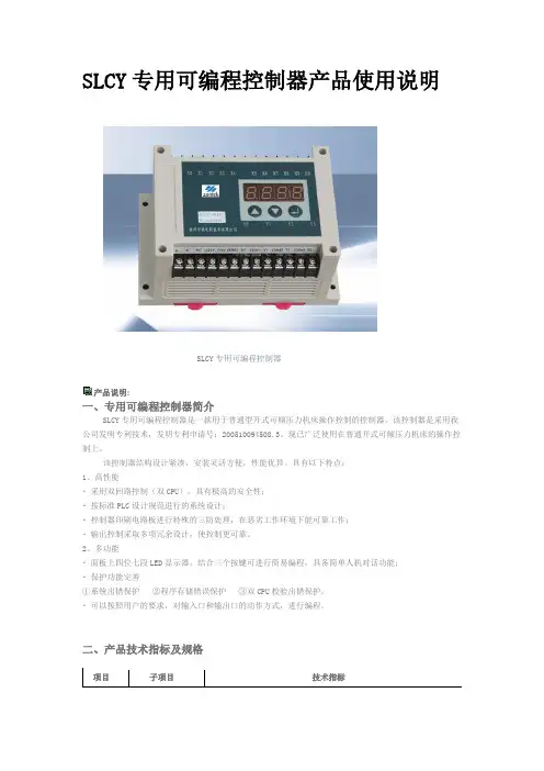
SLCY专用可编程控制器产品使用说明SLCY专用可编程控制器产品说明:一、专用可编程控制器简介SLCY专用可编程控制器是一款用于普通型开式可倾压力机床操作控制的控制器,该控制器是采用我公司发明专利技术,发明专利申请号:200510094508.3。
现已广泛使用在普通开式可倾压力机床的操作控制上。
该控制器结构设计紧凑,安装灵活方便,性能优异。
具有以下特点:1、高性能▪采用双回路控制(双CPU),具有极高的安全性;▪按标准PLC设计规范进行的系统设计;▪控制器印刷电路板进行特殊的三防处理,在恶劣工作环境下能可靠工作;▪输出控制采取多项冗余设计,使控制更可靠。
2、多功能▪面板上四位七段LED显示器,结合三个按键可进行简易编程,具备简单人机对话功能;▪保护功能完善①系统出错保护②程序存储错误保护③双CPU校验出错保护。
▪可以按照用户的要求,对输入口和输出口的动作方式,进行编程。
二、产品技术指标及规格附:产品使用说明书序言谢谢您采用我公司生产的安全型压力机自适应控制器(以下简称控制器)。
该控制器是采用我公司发明专利技术,自主开发的安全性压力机自适应控制器,发明专利号:200510094508.3。
该控制器结构设计紧凑,安装灵活方便,性能优异。
具有以下特点:● 高性能― 能够自动适应不同型号的压力机,可以自动设置压力机单次操作的时间;― 采用双回路控制(双CPU),具有极高的安全性;― 按标准PLC设计规范进行的系统设计;― 控制器印刷电路板进行特殊的三防处理,在恶劣工作环境下能可靠工作;― 输出控制采取多项冗余设计,使控制更可靠。
● 多功能― 控制器除提供单次和连续工作模式外,最新推出拉伸工作模式。
― 面板上四位七段LED显示器,结合三个按键可进行简易编程,具备简易人机对话功能;― 保护功能完善① 系统出错保护② 接近开关失效保护③ 程序存储错误保护④ 双CPU校检出错保护⑤ 电磁铁动作出错保护1、SLCY1004B型号说明2、产品技术指标及规格项 目子项目 技术指标输入额定电压单相:AC110V ,50HZ/60HZ 变动容许值电压:-20%~+20%电压矢衡率:<3% 频率:±5%输出额定开关容量 AC125V,10A 环境使用场合周围空气中无导电尘埃、酸、盐、腐蚀性及爆炸性气体周围环境温度 -10℃~+40℃相对湿度 40℃时不超过50%,20℃以下时不超过90% 振动 最大振动加速度应不超过5.9m/s² 结构冷却方式自然风冷安装方式壁挂式,柜内安装3、端子说明输入端接线输出端接线4、操作方法显示窗:用于显示控制器的工作模式及各种信息。
智能节能照明控制器“保瓦博士”S L C系列安装及使用手册广州保瓦电子科技有限公司目录一、安全注意事项 (1)二、概述 (2)三、功能 (2)3.1 控制 (2)3.2 保护 (3)3.3 界面 (3)3.4 通讯 (4)四、技术指标 (4)五、安装 (5)六、推荐接线图 (6)七、典型工作曲线 (11)八、菜单结构 (12)九、指示灯及按键功能 (13)十、操作说明 (14)10.1 查询与设置模式之间切换 (14)10.2 设置模式切换界面与参数编辑 (15)10.3 光控/时控 (16)10.4 时控输出 (18)10.5 时间设置 (18)10.6 天文设置 (19)10.7 启动设置 (20)10.8 输出设置 (20)十一、常见故障排除 (21)附录一:城市经纬度 (22)附录二、上位机数据通道表 (33)一、安全注意事项1.由于SLC系列智能节能照明控制器采用半导体功率器件,因此不能作为检修时的电气隔离使用,线路上应使用空气开关或带熔断器的刀闸作为电气隔离。
2.在接入电源的状况下,不管SLC系列智能节能照明控制器处在任何状态,均不得触摸SLC系列智能节能照明控制器的任何端子,否则将有触电危险!3.在SLC系列智能节能照明控制器的配线回路上必须使用相应容量的快速熔断器或断路器作为短路保护元件。
4.对于带有补偿电容的灯具,请将功能开关中的单灯补偿开关打开,并设置预热时间应大于5分钟。
5.光控探头应安装在不易被人为光源干扰的位置。
6.SLC系列智能节能照明控制器任何状态下都能设置参数,参数设置完毕后须将SLC系列智能节能照明控制器保持运行。
7.在停止状态下SLC系列智能节能照明控制器不起控制作用。
1二、概述SLC系列智能节能照明控制器是以微处理器技术和现代电力电子先进技术为基础开发的高性能产品,能有效的降压及限压,延长灯具的使用寿命,减少维护费用,降低维护人员的工作量,节能效果达10%-35%,投资少见效快。
罗克韦尔A-B公司不同型号的PLC所支持的指令有差异,但是基本逻辑指令却是大家所共有的(SLC500、ML1000与PLC5的基本指令大致相同)在梯形图中用基本逻辑指令代替继电器-接触器控制的硬件逻辑电路。
基本编程指令共分为三类:位指令、计时器指令和计数器指令。
位指令是对数据的单个位进行操作,用于监控数据表中的位状态,如输入位、输出位或者计时器控制字的位等存储器所有空间上的位。
在处理器运行时,可以根据其所在梯级的逻辑条件使某位位置位或复位状态。
应用程序可以根据需要对一位进行多次访问。
但是不推荐多条输出指令用同一个位地址。
1.数据文件的表示格式在对位指令编程时,会涉及到下列数据文件,其表示格式分别为:1)输出和输入数据文件(文件O:0和I:1)这些数据文件表示外部的输出与输入,在文件1中的各位表示外部输入。
文件0中的各位表示外部输出。
输出和输入的地址格式如表1所示。
表12)状态文件(文件S2:)状态文件允许用户监控操作系统的工作状况,并可指挥操作系统按要求进行工作。
这些功能均可通过使用状态文件设置相应的控制位,监控硬件和软件故障及其它的状态信息来实现。
注意:如果你要向状态文件写入数据,必须首先完全了解状态文件的功能。
状态文件地址格式如表2所示:举例:S:1/15 元素1,位15。
这是“首次扫描"位,用户可以在程序中使用它初始化指令。
S:3 元素3。
这一元素的低位字节是当前扫描时间。
高位字节是看门狗扫描时间。
3)位文件(B3:)文件3是位文件,主要用于位(继电器类逻辑)指令,移位寄存器和顺序器指令。
可以通过指定元素号和元素内的位编号(0到15)来访问位。
也可以通过位的顺序编号直接访问位。
用户也可以只访问该文件的元素。
位地址格式如表3所示:4)计时器和计数器文件(T4:和C5:)赋值给计时器和计数器的地址分别用Tf:e.s/b和Cf:e.s/b表示。
计时器和计数器文件的具体含义表4与表5所示:表55)控制文件(R6:)有些指令使用不同的控制位。
S L C使用说明及编程软件文件管理序列号:[K8UY-K9IO69-O6M243-OL889-F88688]S7-200P L C使用说明一、PLC的结构与工作原理PLC的结构PLC的类型繁多,功能和指令系统也不尽相同,但结构与工作原理则大同小异,通常由主机、输入/输出接口、电源、编程器扩展器接口和外部设备接口等几个主要部分组成。
1.主机主机部分包括中央处理器(CPU)、系统程序存储器和用户程序及数据存储器。
CPU是PLC的核心,它用以运行用户程序、监控输入/输出接口状态、作出逻辑判断和进行数据处理,即读取输入变量、完成用户指令规定的各种操作,将结果送到输出端,并响应外部设备(如编程器、电脑、打印机等)的请求以及进行各种内部判断等。
PLC的内部存储器有两类,一类是系统程序存储器,主要存放系统管理和监控程序及对用户程序作编译处理的程序,系统程序已由厂家固定,用户不能更改;另一类是用户程序及数据存储器,主要存放用户编制的应用程序及各种暂存数据和中间结果。
2.输入/输出(I/O)接口I/O接口是PLC与输入/输出设备连接的部件。
输入接口接受输入设备(如按钮、传感器、触点、行程开关等)的控制信号。
输出接口是将主机经处理后的结果通过功放电路去驱动输出设备(如接触器、电磁阀、指示灯等)。
I/O接口一般采用光电耦合电路,以减少电磁干扰,从而提高了可靠性。
I/O点数即输入/输出端子数是PLC的一项主要技术指标,通常小型机有几十个点,中型机有几百个点,大型机将超过千点。
3.电源图中电源是指为CPU、存储器、I/O接口等内部电子电路工作所配置的直流开关稳压电源,通常也为输入设备提供直流电源。
4.编程器编程器是PLC的一种主要的外部设备,用于手持编程,用户可用以输入、检查、修改、调试程序或监示PLC的工作情况。
除手持编程器外,还可通过适配器和专用电缆线将PLC与电脑联接,并利用专用的工具软件进行电脑编程和监控。
5.输入/输出扩展单元I/O扩展接口用于连接扩充外部输入/输出端子数的扩展单元与基本单元(即主机)。
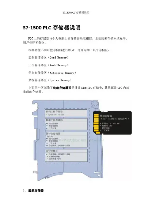
S7-1500 PLC存储器说明PLC上的存储器与个人电脑上的存储器功能相似,主要用来存储系统程序、用户程序和数据。
根据功能不同可把存储器进行细分,可分为如下几个存储区:装载存储器区(Load Memory)工作存储器区(Work Memory)保存存储器区(Retentive Memory)系统存储器区(System Memory)上面四个区域除了装载存储器区是外插SIMATIC存储卡,其他都是CPU内部集成的存储器。
1、装载存储器在S7-300/400系列PLC中装载存储器也就是外插的MMC卡,这个卡是Flash Memory,断电后卡中的信息不会丢失。
对于S7-1500 CPU的装载存储器,只能通过外插存储卡扩展,容量最大支持到32G。
装载存储器主要存储项目中的程序块、数据块、工艺对象、硬件配置,就是你用博途编写程序和组态硬件产生的所有数据。
在你下载程序的过程中,首先是存储到装载存储器中,然后再复制到工作存储器中,程序和数据在工作存储器中运行。
对CPU的任何操作都不会让SIMATIC存储卡的用户程序丢失,也不会损坏程序。
所以无论你CPU怎么损坏,用户程序是不会丢失的,但是没有了SIMATIC存储卡,即使你买再多的CPU,依然要重写程序。
装载存储器类似电脑的硬盘。
在S7-300/400 PLC中,装载存储器不存储项目中的符号和注释等信息,但是S7-1500 PLC的装载存储器可以保存变量的符号、注释信息以及PLC的数据类型。
西门子SIMATIC存储卡的知识以后专门介绍,这篇文章你知道所谓装载存储器就是S7-300/400上的MMC卡,S7-1500上这张卡叫做SIMATIC存储卡。
2、工作存储器工作存储器是集成在CPU内部的RAM存储器,容量根据型号确定,不能扩展。
所以在选择CPU时除了要考虑指令的处理速度,还要考虑最终程序的大小。
如果写完程序发现CPU没法运行,就比较麻烦了。
可分为代码工作存储器和数据工作存储器,分别用来保存与程序运行有关的代码(OB/FC/FB)和数据块(DB)。
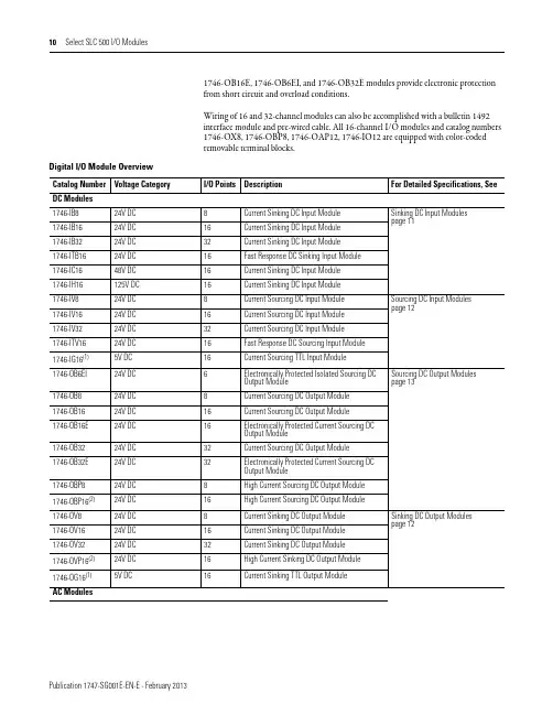
1746-OB16E, 1746-OB6EI, and 1746-OB32E modules provide electronic protectionfrom short circuit and overload conditions.Wiring of 16 and 32-channel modules can also be accomplished with a bulletin 1492interface module and pre-wired cable. All 16-channel I/O modules and catalog numbers1746-OX8, 1746-OBP8, 1746-OAP12, 1746-IO12 are equipped with color-codedremovable terminal blocks.Digital I/O Module OverviewCatalog Number Voltage Category I/O Points Description For Detailed Specifications, See DC Modules1746-IB824V DC8Current Sinking DC Input Module Sinking DC Input Modulespage111746-IB1624V DC16Current Sinking DC Input Module1746-IB3224V DC32Current Sinking DC Input Module1746-ITB1624V DC16Fast Response DC Sinking Input Module1746-IC1648V DC16Current Sinking DC Input Module1746-IH16125V DC16Current Sinking DC Input Module1746-IV824V DC8Current Sourcing DC Input Module Sourcing DC Input Modulespage121746-IV1624V DC16Current Sourcing DC Input Module1746-IV3224V DC32Current Sourcing DC Input Module1746-ITV1624V DC16Fast Response DC Sourcing Input Module1746-IG16(1)5V DC16Current Sourcing TTL Input Module1746-OB6EI24V DC6Electronically Protected Isolated Sourcing DCOutput Module Sourcing DC Output Modules page131746-OB824V DC8Current Sourcing DC Output Module1746-OB1624V DC16Current Sourcing DC Output Module1746-OB16E24V DC16Electronically Protected Current Sourcing DCOutput Module1746-OB3224V DC32Current Sourcing DC Output Module1746-OB32E24V DC32Electronically Protected Current Sourcing DCOutput Module1746-OBP824V DC8High Current Sourcing DC Output Module1746-OBP16(2)24V DC16High Current Sourcing DC Output Module1746-OV824V DC8Current Sinking DC Output Module Sinking DC Output Modulespage121746-OV1624V DC16Current Sinking DC Output Module1746-OV3224V DC32Current Sinking DC Output Module1746-OVP16(2)24V DC16High Current Sinking DC Output Module1746-OG16(1)5V DC16Current Sinking TTL Output ModuleAC ModulesVoltage, Off-State Input, max. 5.0V DC 10V DC 20V DC5V DC Nominal Input Current 8 mA @ 24V DC 5.1 mA @ 24V DC 4.1 mA @ 48V DC2.15 mA @ 125V DC 2.25 mA @ 132V DC 8 mA @ 24V DC Current, Off-State Input, Max. 1 mA 1.5 mA 0.8 mA 1.5 mA Signal On Delay, Max 8 ms max 3 ms max 4 ms max 9 ms max 0.30 ms max Signal Off Delay, Max8 ms max3 ms max4 ms max9 ms max0.50 ms max(1)If the input module is connected in parallel with an inductive load, use surge suppression across the load to protect the input module from damage caused by reversevoltage. Refer to the SLC 500 Modular Hardware Style User Manual, publication 1747-UM011, for more information on surge suppression.(2)Maixumum Points ON Simultaneously: 16 @ 146V DC and 30 °C (86 °F); 12 @ 146V DC and 50 °C (122 °F); 14 @ 132V DC and 55 °C (131 °F); 16 @ 125V DC and60 °C (140 °F).Sinking DC Input ModulesSpecifications1746-IB81746-IB161746-IB321746-IC161746-IH16(1)1746-ITB16Sourcing DC Input ModulesSpecifications 1746-IG161746-IV81746-IV161746-IV321746-ITV16Number of inputs 168163216Points per common 16816816Voltage category 5V DC 24V DC 24V DC24V DC24V DC Operating voltage range 4.5…5.5V DC (1)10…30V DC 15…30V DC@ 50 °C (122 °F)15…26.4V DC@ 60 °C (140 °F)10…30V DC Backplane current (mA) @ 5V 140 mA 50 mA 85 mA 50 mA 85 mA Backplane current (mA) @ 24V 0 mA 0 mA 0 mA 0 mA 0 mA Voltage, off-state input, max.2…5.5V DC 5.0V DC 5.0V DC5.0V DC 5.0V DC Nominal input current 3.7 mA @ 5V DC 8 mA @ 24V DC5.1 mA @ 24V DC 8 mA @ 24V DC Current, off-state input, max. 4.1 mA 1 mA 1.5 mA 1.5 mA Signal on delay, max 0.25 ms max 8 ms max 3 ms max 0.30 ms max Signal off delay, max0.50 ms max8 ms max3 ms max0.50 ms max (2)(1)50 mV peak-to-peak ripple (max.)(2)Typical signal delay for this module: ON = 0.1 ms, OFF = 0.25 ms @ 24V DC.Sinking DC Output ModulesSpecifications 1746-OG161746-OV81746-OV161746-OV321746-OVP16(5)Number of outputs 168163216Points per common 168161616Voltage category 5V DC24V DCOperating voltage range 4.5…5.5V DC (2)10…50V DC 5…50V DC20.4…26.4V DC Backplane current (mA) @ 5V180 mA 135 mA 270 mA 190 mA 250 mA Backplane current (mA) @ 24V0 mA0mA0 mA0 mA0 mAVoltage drop, on-state output, max.—************************************Load current, min.0.15 mA1 mA 1 mA 1 mA 1 mA Leakage current, off-state output,max 0.1 mA 1 mA (3) 1 mA (3) 1 mA (3) 1 mA (3)Signal On Delay, max (resistive load)0.25 ms 0.1 ms 0.1 ms 0.1 ms 0.1 ms (6)Signal Off Delay, max (resistive load)0.50 ms 1.0 ms1.0 ms1.0 ms1.0 msContinuous current per moduleN/A 8.0 A @30 °C (86 °F)4.0 A @60 °C (140 °F)8.0 A @ 0…60 °C (32…140 °F) 6.4 A @ 0…60 °C (32…140 °F)Continuous current per point24 mA 1.0 A @30 °C (86 °F)0.5 A @60 °C (140 °F)0.50 A @30 °C (86 °F)0.25 A @60 °C (140 °F)(4)0.50 A @ 30 °C 0.25 A @ 60 °C 1.5 A @30 °C (86 °F)1.0 A @60 °C (140 °F)(7)Surge current per point for 10 ms (1)N/A3.0 A1.0 A @30 °C (86 °F)1.0 A @60 °C (140 °F)4.0 A (8)(1)Repeatability is once every 1 s @ 30 °C (86 °F). Repeatability is once every 2 s @ 60 °C (140 °F).(2)50 mV peak to peak ripple, max.(3)To limit the effects of leakage current through solid-state outputs, a loading resistor can be connected in parallel with your load. For transistor outputs, 24V DC operation,use a 5.6 K Ω, 1/2 W resistor.(4)Recommended surge suppression: For transistor outputs, when switching 24V DC inductive loads, use a 1N4004 diode reverse-wired across the load. Refer to the SLC 500Modular Hardware Style User Manual, publication 1747-UM011, for more information on surge suppression.(5)The 1746-OVP16 module features a fused common and blown fuse LED indicator.(6)Fast turn-off modules provide fast OFF delay for inductive loads. Fast turn-off delay for inductive loads is accomplished with surge suppressors on this module. Asuppressor at the load is not needed unless another contact is connected in series. If this is the case, a 1N4004 diode should be reverse wired across the load. This defeats the fast turn-off feature. Comparative OFF delay times for 1746-OB8, 1746-OV8 and fast turn-off modules, when switching Bulletin 100-B110 (24 W sealed) contactor, are: 1746-OB8 and 1746-OV8 modules OFF delay = 152 ms; fast turnoff modules OFF delay = 47 ms.(7)Fast off-delay for inductive loads is accomplished with surge suppressors on the 1746-IB6EI and 1746-OBP8 series B and later, 1746-OB16E series B and later, 1746-OBP16and 1746-OVP16 modules. A suppressor at the load is not needed unless another contact is connected in series. If this is the case, a 1N4004 diode should be reverse-wired across the load. This defeats the fast turn-off feature.(8)Surge current = 32 A per module for 10 ms.Sinking DC Output ModulesSpecifications 1746-OG161746-OV81746-OV161746-OV321746-OVP16(5)Sourcing DC Output ModulesSpecifications1746-OB6EI1746-OB81746-OB161746-OB16E1746-OB321746-OB32E1746-OBP8(4)1746-OBP16Number of outputs 6 ElectronicallyProtected 81616 Electronically Protected 3232 Electronically Protected 816(5)Points per common Individually isolated 816161616416Voltage category24V DCOperating voltage range10 …30V DC 10…50V DC 10…30V DC 5…50V DC 10…30V DC 20.4…26.4V DC Backplane current (mA) @ 5V46 mA 135 mA 280 mA 135 mA 190 mA 135 mA250 mA Backplane current (mA) @ 24V0 mA 0 mA0 mA0 mA0 mA0 mA 0 mA0 mAPre-Wired Cables for 1746 Digital I/O ModulesThese pre-wired cables have a pre-wired removable terminal block (RTB) on one end to connect to the front of a Bulletin 1746 digital I/O module and a connector on the other end to plug into a 20- or 40-terminal IFM/XIM. Y ou must first select the IFM/XIM from one of the preceding selection tables.Relay Master and Expander 40-Terminal XIMsDescription Catalog Number I/O Module Catalog Number 1746-IB32IV32OB32OB32E OV32Relay Master40-pin master with eight (8) 24V DC relays 1492-XIM4024-8R ––H H –40-pin master with sixteen (16) 24V DC relays 1492-XIM4024-16R ––H H –40-pin master with sixteen (16) 24V DC relays with fusing1492-XIM4024-16RF––HH–Relay ExpanderExpander with eight (8) 24V DC relays 1492-XIM24-8R ––(1)(1)–Expander with eight (8) 120V AC relays1492-XIM120-8R–––––Expander with sixteen (16) 24V DC relays with fusing 1492-XIM24-16RF ––(2)(2)–Fusible Expander8-channel expander with 24V DC blown fuse indicators1492-XIMF-F24-2––(1)(1)–8-channel expander with 120V AC blown fuse indicators1492-XIMF-F120-2–––––Feed-through ExpanderExpander with eight (8) feed-through channels 132V AC/DC max1492-XIMF-2––(1)(1)–(1)Two or three expanders can be connected to a master to provide a total of 32 outputs. An extender cable is included with each expander to connect it to the master.(2)Can have one expandable module per master.Cable Catalog Number Standard Cable Lengths Build to Order Available Number of Conductors Mating I/O Module Catalog Number 1492-CABLE (1)A 0.5, 1.0, 2.5, 5.0 m Yes 201746-IA16, -IM161492-CABLE (1)B 0.5, 1.0, 2.5, 5.0 m Yes 201746-IB16, -IH16, -IN16, -ITB16, -ITV161492-CABLE (1)C 0.5, 1.0, 2.5, 5.0 m Yes 201746-OA161492-CABLE (1)CR 0.5, 1.0, 2.5, 5.0 m Yes 201746-OA161492-CABLE (1)D 0.5, 1.0, 2.5, 5.0 m Yes 201746-OW16, -OX81492-CABLE (1)E0.5, 1.0, 2.5, 5.0 mYes201746-IG16, -OB16, -OB16E, -OBP16, -OG16, -OV16, -OVP161746-ITV1685 mA 0 mA 0.200 W 0.425 W 3.625 W 1746-IV850 mA 0 mA 0.200 W 0.250 W 1.90 W 1746-IV1685 mA 0 mA 0.200 W 0.425 W 3.60 W 1746-IV32106 mA0 mA0.200 W0.530 W6.90 W(1)Power supply loading for series D and later modules.Digital Input ModulesCatalog Number Backplane Current (mA) @ 5V Backplane Current (mA) @ 24V Watts per point Thermal dissipation, min.Thermal dissipation, max.Digital Output ModulesCatalog Number Backplane Current(mA) @ 5V Backplane Current (mA) @ 24V Watts per point Thermal dissipation, min.Thermal dissipation, max.1746-OA8185 mA 0 mA 1.00 W 0.925 W 9.00 W 1746-OA16370 mA 0 mA 0.462 W 1.85 W 9.30 W 1746-OAP12370 mA 0 mA 1.00 W 1.85 W 10.85 W 1746-OB8135 mA 0 mA 0.775 W 0.675 W 6.90 W 1746-OB16280 mA 0 mA 0.338 W 1.40 W 7.60 W 1746-OB32(1)190 mA 0 mA 0.078 W 2.26 W 4.80 W 1746-OBP8135 mA 0 mA 0.300 W 0.675 W 3.08 W 1746-OBP16250 mA 0 mA 0.310 W 1.25 W 6.21 W 1746-OB16E 135 mA 0 mA 0.338 W 1.40 W 7.60 W 1746-OB32E 190 mA 0 mA 0.078 W 2.26 W 4.80 W 1746-OG16180 mA 0 mA 0.033 W 0.90 W 1.50 W 1746-OV8135 mA 0 mA 0.775 W 0.675 W 6.90 W 1746-OV16270 mA 0 mA 0.338 W 1.40 W 7.60 W 1746-OV32(1)190 mA 0 mA 0.078 W 2.26 W 4.80 W 1746-OVP16250 mA 0 mA 0.310 W 1.25 W 6.21 W 1746-OW445 mA 45 mA 0.133 W 1.31 W 1.90 W 1746-OW885 mA 90 mA 0.138 W 2.59 W 3.70 W 1746-OW16170 mA 180 mA 0.033 W 5.17 W 5.70 W 1746-OX885 mA90 mA0.825 W2.59 W8.60 W(1)Power supply loading for series D and later modules.。
小源科普SLC、MLC、TLC、QLC究竟是什么意思?固态硬盘颗粒介绍更新时间:2021-07-30我们都知道固态硬盘的数据是储存在NAND闪存中的,我们的资料、媒体、程序等等均以二进制的0和1储存在NAND闪存中。
我们再微观一点去看每一个Cell是如何储存数据的。
在SLC中(Single Level Cell)中,一个Cell可以有两个电位,即每个电位都可以表达0或者1,即1bit信息。
而在MLC(Multi Level Cell)中单个Cell则可以储存更多的数据,即00、01、10、11四种,即2bit信息。
而在TLC(Triple Level Cell)中则可以储存3bit信息,以此类推QLC (Quadruple Level Cell)则是单个Cell可以储存4Bit的信息。
而随着晶体管制造工艺的提升PLC在某个时间节点也一定会到来。
从SLC到目前普及开来的TLC,单个Cell储存密度的提升带来一个显而易见的好处,就是固态价格大幅下降,准确点说是每G价格的大幅下降。
在2013年的时候,一块120G的固态硬盘往往就需要600-700元的价格。
那个时候大家还只是将系统和一些必要软件装在固态里面,像把大型单机装在固态里面还属于“土豪”行为,而今一块1TB的固态也仅仅需要不到700元。
相信大家日常使用中,固态会全方位得到应用,机械硬盘反而将成为了比较少见的硬件。
但是随着密度的逐步提升,寿命也成为了大家非常关心的问题。
了解固态的朋友应该都知道,NAND芯片是存在理论寿命的。
以SLC 颗粒为例,它的擦除(P/E)寿命大概是1万-10万次全盘,而MLC则是3000-5000次。
TLC则下降到了1000-3000次。
但是大家需要了解的一点是,在日常使用中,大多是读取的操作,比如我安装了一个游戏,然后我在玩游戏的过程中实际上是读取硬盘中的游戏,而这个过程对寿命几乎没有影响!而且现在主控都有自己的均衡策略,即保障硬盘所有的NAND芯片使用雨露均沾,避免某一个NAND芯片提前损坏!在算法的加持下,其实正常使用固态的寿命是根本用不完的!另外随着工艺的提升,或许未来密度大寿命低的问题也将持续得到改进。
闪存指南金士顿® 是全球领先的独立内存产品制造商,提供各种利用闪存芯片存储数据的闪存卡、USB 闪存盘和固态硬盘 (SSD)(统称为闪存设备)。
本指南旨在介绍现有的各种技术和闪存产品。
注意:由于闪存技术不断变化,本文档所述规格可能随时更改,恕不另行通知。
1.0 闪存:助力新一代闪存设备东芝于 20 世纪 80 年代发明了闪存,这项新存储器技术让存储器设备在断开电源时也能保留已存储的数据。
从那时起,闪存技术逐步发展成为各种消费类及工业设备的首选存储介质。
在消费类设备领域,闪存广泛应用于:••笔记本电脑••个人电脑••平板电脑••数码相机••全球定位系统•(GPS)••手机••固态音乐播放器,例如•••电子乐器•MP3•播放器••电视•••便携式和家庭视频游戏机闪存还应用于许多工业应用领域,其中断电情形中的可靠性和数据保持性是两项关键要求。
这些领域包括:••安保系统/网路摄影机••军事系统••嵌入式计算机••机顶盒••网络和通信产品••无线通信设备••零售管理产品••销售点设备•((例如手持扫描器))请注意:大多数金士顿闪存产品经过精心设计和严格测试,可兼容消费类设备。
对于超出标准日常消费类用途的工业应用或特殊用途应用,建议您直接联系金士顿。
这可能需要特殊配置,特别是对于严重影响闪存单元耐久性的应用(参见第•3.0•章)。
2.0 SSD、闪存卡和 USB 闪存盘容量闪存设备上所列容量有部分会用于格式化及其他功能,并非全部用于数据存储。
在设计和生产闪存设备时,需要采取相应的步骤,以确保设备能够可靠地工作并允许主机设备(计算机、数码相机、平板电脑、手机等)访问存储器单元,即存储和检索位于闪存设备上的数据。
格式化包括以下操作:1.•测试闪存设备中的每个存储器单元。
2.•找出所有有问题的单元,并采取相应的步骤确保不会对有故障的单元进行数据写入或读取。
3.•保留部分单元作为“备用”。
闪存单元拥有很长的寿命,但也是有限的。

S MART L OAD C ELL USER’S MANUAL Smart Load Cell TRQ1/TPLtorque / top load tester familySerial numbers:TRQ1 torque tester: ST-E……TPL-….. Top Load tester: ST-E……Date of purchase: ……………………...Warranty: 3 yearsTRQ1 TORQUE- AND TPL TOP LOAD TESTER KITINSTALLDownload: www.suretorque.eu / Support / Downloads / SmartLoadCell_Single – v_1.9.1 – apkhttp://www.suretorque.eu/media/wysiwyg/download/slc_s_v1.9.1.apkSystem requirements: Android 4.4 or higher, 1 GB RAM, 1 GHz Processor, 4 GB ROM Install the SmartLoadCell Android application on your device!SETUP – QUICK OVERVIEWPersonalize your settings: Enter menu / setupPair your SmartLoadCell with your device and connect. When pairing, all the important SmartLoadCell parameters will be uploaded to the phone from the SmartLoadCell’s memory (calibration data, load cell type, measuring range, etc.)TPL3 & TPL4 SETUPTPL3&TPL4 are having digital displacement control. This means that the displacement of the unit is measured and a displacement stop trigger can be defined for the test.We recommend to use TPL3&TPL4 with the following settings:DOING A TEST1.Make sure the unloaded value is 0. If not, hit TARE button2.Tap the diagram area to start recording3.Perform your testContinuous and multiple tests can be stopped by tapping the diagram area again.Single and Double peak tests will stop automatically.4.After the test you may add a comment to the test. You can also add the samecomment to more test with checking “Remember” field in the comment window5.You may save the result with the save button (unless you have selected auto save)TRQ1When changing adapters on the TRQ1 (cap fitment support or neck fitment) the mounting bolt torque should be 1.5-2 Nm!TPLWhen testing with the TPL make sure the TPL unit is in level and centered!Never lay the TPL unit directly on the spikes to avoid the erosion of the spikes –use plastic or aluminum spacers like the ones we provide:Flat base disc Stepped base disk (A)Head plate (B) for bigger chucks Usually there is about 1 mm height difference between the starwheel and the neck guide – This difference must be equalized with spacers under the TPL unit We recommend to use 2 plastic spacers, whereof the one that comes on the spike is 1 mm thinner.TPL3&TPL4With the above settings of the TPL3&4 the test will be performed as:-Tap the graph area to start the test-When starting to lift the chuck the test willbe started when force exceeds the FORCETRIGGER (eg. 1 kg) and this triggers thestart of the displacement measurement.-When the displacement is changed by thepreset Stop trigger displacement (eg 3 mm–set in the Advanced setup) themeasurement is stopped-Force result is going to be the Forcemeasured at the maximum presetdisplacement (2 mm in our example)-During the test you will see that the test letsay at 1,5 mm and will be stopped at 4,5mmSETUP – A LIITLE MORE IN THE DETAILSMeasuring modes:Continuous – records all measuring points from start to stopResult: maximum value.This mode is ideal for monitoring longer procedures with several peaks as chuck torque testingSingle peak – Measurement stopsautomatic after the 1st peak. Result: maximum valueThis mode is ideal for monitoring short procedures with only 1 peak as cap release torque testingDouble peaks – Measurement stops automatic after the 2nd peak. Results: Max1, Max2 Multiple peaks – Records only the maximum values of the test cycles – 1 test cycle is represented by 1 point on theThis mode is ideal for monitoring short procedures with 2 discrete peaks as cap release and warranty ring break torque testing diagram. This test is generally used for testing hundreds of cyclesResult: maximum of the peaks1. Select measuring unit2. Set trigger level – Trigger level is a load level that starts and stops themeasurement recording - “start -stop signal” of the measurement. As long as the measured value is under the trigger, recording will not be started. Measurement will be stopped (or paused), if the measured value drops under the trigger level. Recommended level is between 2-15% of the expected maximum value.If you need range checking, set high and low limits. Values will be displayed with different colors: blue – under range green – in range red – over range(by 2-channel unit select the “primary” channe l too)It is possible to switch on a sound signal for the exceeding of the high limit with the ring button.3. Set time out (relevant only in double peaks mode) – This time defines how long theinstrument waits for the start of the second peak’s measurement. If time out elapses without value over the trigger, MAX2 will be 0.4. Set Y scale for the diagram’s scaling (default setting is the maximum of the cell,recommended value is a little above your expected maximum) 5. Select sample rate (6,25 – 400 Hz, recommended: 50-200 Hz) 6. Set turn off time (for automatic shut down after disconnecting) 7. Check Auto save box if you want to save all results automaticFURTHER FEATURESCLEAR button on the main screen will clear the screenCLEAR button on the SETUP screen will clear all the setup parameters including the SmartLoadCell pairing.Status LED – Status LED has 3 states:- Green flashing – unit is ready to use, but unconnected - Blue flashing – unit connected - Red - chargingMenu /History – All saved results can be reviewed. Results can be deleted one by one (or in bulk with hitting the trash button longer). Diagrams can be scrolled and zoomed.Menu/Export to XML will create an export_11111_22222.xml file in the Download folder of your android device. Download file can be forwarded to PC via Bluetooth, email, internet or USB cable.SHUTTING DOWNShutting down the SmartLoadCell – To turn off select the turn off button on the main screen or keep the power button pushed for 10 seconds on the SmartLoadCell unit.CHARGINGCharging – SmartLoadCells can be charged with any micro USB charger. While charging the status led on the unit will be red. Battery state can be monitored by hitting the battery icon on the main screen. Battery is enough for about 10 hours of operation.Please note that when battery is almost discharged, it is possible that you experience some spikes in the measurement. It is recommended not to discharge batteries under 10%.DATA MANAGER PROGRAMData manager program for pc can be downloaded in zip form from:www.suretorque.eu / Useful information / Support / SLC_DAQ_1.1link: http://www.suretorque.eu/media/wysiwyg/download/SLC_Single_DAQ_2_1_2.zipWith the program you may view all the measurement results saved in the xml. Results can be exported in csv format or printed in report form.CALIBRATIONLoad cells’ calibration should be generally checked (verified) every year. Frequency of the calibration check may be higher or lower upon the application and the stress of the load cell. Load cell must be recalibrated only in the case, if the measured values are outside of the tolerance range during the calibration check.Calibration check / calibration of the TRQ1:1.Assemble the calibration kit2.Mount the TRQ1 on the calibration stand3.Apply the calibration bar in the place of the torque fitment. Mounting bolt torque:1.5-2.0 Nm4.Stress the load cell first –apply about 20 LbIn(2Nm) torque changing to bothdirection for 5-6 times5.Make sure the unloaded torque reading is 0 – if not, hit TARA6.Apply torque by hanging the weight on both sides to different positions and repeatat least 3 times7.If the measured values are within the tolerance range (+/-1%), calibration is ok. Ifnot, load cell must be recalibratedRecalibration with loads:1.Make sure all the calibration accessories are present and the SmartLoadCell is inthe calibration position2.Set sample rate to 50Hz3.Enter the Calibration menu with typing the calibration password4.Make sure the UNIT and the FULL LOAD are set correctly5.Apply the +MAX load and press OK6.Remove load and press OK again7.If your SmartLoadCell requires negative load calibration too, repeat the last 2 stepswith the negative load calibration too!Advanced recalibration with mV/V values1.Enter the advanced load calibration password2.Make sure the UNIT and the FULL LOAD are set correctly3.Enter the provided mV/V value to the +MAX, +ZERO (and –MAX, -ZERO ifprovided)!4.Hit Save to save the modified calibration data’s!Calibration password: 10562348Advanced calibration password: __________________UNITS & CONVERSATIONTORQUEinlb: inch-poundftlb: foot-poundNm: Newton-meterdNm: deci newton-meter - 0,1 NmNcm: Newton-cm, - 0,01 NmLbfIn LbfFt Nm dNm Ncm Kgfcm1 0.083 0.113 1.13 11.3 1.152112 1 1.356 13.56 135.613.82558.851 0.738 1 10 10010.19720.885 0.074 0.1 1 10 1.01970.089 0.007 0.01 0.1 10.10200.867960.0720.09807 0.98066 9.80661 1FORCEN: NewtonLb: Pounds forceKg: Kilograms forceT: TonN Kg Lbf Ton1 0.102 0.2250.00019.807 1 2.2050.0014.448 0.454 10.000459806.81 1000 2204.6 1TROUBLESHOOTINGSmartLoadCell unit connected, but is seems not measuring:It may happen that the pairing is not successful at the first time. In this case disconnect and connect again.If it won’t help: enter MENU/SETTINGS and CLEAR the settings, then select Smart Cell again and wait until the cell data’s are uploaded (Range value will be filled and status led turns from green to blue)SmartLoadCell application freezes:Enter settings/apps in on your Android device and force stop the application. If this doesn’t help it is recommended to uninstall the application and then reinstall it again. Application was developed with English language settings. If you experience malfunction with different language setting, close the application, change language to English and run the application again.MAINTENANCESmatLoadCells are precisions measuring devices, handle them with care! In normal case SmartLoadCells will not require any preventive or systematic maintenance.Battery is to be changed if it wears out. Battery type: Nokia BL-5C, 1000 mAh. Battery is located under the cover of the SmartLoadCell unit. If cover is sealed, pay attention on sealing it with clear silicone when reclosing the cover!CONTACTManufacturing and distribution:Sure Torque Europe ltd.H-1134 Budapest, Rozsafa u. 13., HUNGARYTel.: +36.1.3917389Fax: +36.1.3917310******************www.suretorque.eu。
SLC 500 System OverviewThe Allen-Bradley SLC 500 is a small chassis-based family of programmable controllers, discrete, analog, and specialty I/O, and peripheral devices. The SLC 500 family delivers power and flexibility with a wide range of communication configurations, features, and memory options. The RSLogix 500 ladder logic programming package provides flexible editors, point-and-click I/O configuration, and a powerful database editor, as well as diagnostic and troubleshooting tools to help you save project development time and maximize productivity.Typical SystemsWith up to 64 K of configurable data/program memory available and over 60 types of I/O modules, as well as a choice of networking options, the SLC system provides apowerful solution for stand-alone or distributed industrial control.TopicPage Select SLC 500 I/O Modules 2Select Network Communications 2Select an SLC 500 Processor 69Select an SLC 500 Chassis 75Select SLC 500 Power Supplies 79Select Programming Software 91Summary101System Overview 3 Local SystemsAt minimum, a modular hardware SLC 500 control system consists of a processor module and I/O modules in a single 1746 chassis with a power supply.You can configure a system with one, two, or three local chassis, for a maximum total of 30 local I/O or communication modules. You connect multiple local chassis together with chassis interconnect cables to extend the backplane signal lines from one chassis to another.Distributed SystemsMore complex systems can use:•distributed I/O.4 System Overview•multiple controllers joined across networks.•I/O in multiple platforms that are distributed in many locations and connectedover multiple I/O links.Choose the processor module with the on-board communication ports you need. Youoptionally add modules to provide additional communication ports for the processor. ForI/O in locations remote from the processor, you can choose between a ControlNet,DeviceNet, or Univeral I/O link. A communication interface module is required in boththe local and remote chassis.Depending upon the communication ports available on your particular SLC controlsystem, you can select operator interfaces that are compatible.Laying Out the SystemLay out the system by determining the amount of I/O necessary, the networkconfigurations, and the placement of components in each location. Decide at this timewhether each chassis will have its own controller or a networked solution.SLC 500 processors are available with a large range of memory sizes (1 K…64 K) and cancontrol up to 4096 input and 4096 output signals. All modular processors except theSLC 5/01 processor are capable of controlling remotely located I/O. By adding an I/Oscanner module, you can use these processors to control/monitor these remotely locatedI/O across ControlNet, DeviceNet, and Universal Remote I/O links.System Overview 5 SLC 500 processors are single-slot modules that you place into the left-most slot of a 1746 I/O chassis. For I/O in a location remote from the processor, the I/O adapter is a single-slot module that you place in the left-most slot of the I/O chassis. SLC 500 modular systems provide separate power supplies which must be mounted directly on the left end of the 1746 I/O chassis.The 1746 I/O chassis are designed for back-panel mounting and available in sizes of 4, 7, 10, or 13 module slots. The 1746 I/O modules are available in densities up to a maximum of 32 channels per module.CommunicationsEvaluate what communications need to occur. Knowing your communications requirements will help you determine which processor and which communications devices your application might require.An SLC processor communicates across the 1746 backplane to 1746 I/O modules in the same chassis in which the processor resides. Various models of SLC processors have various on-board ports for communication with other processors or computers. Also, separate modules are available to provide additional communication ports for communication with other processors, computers, and remotely located I/O.Each processor has one or two built-in ports for either EtherNet/IP, DH+, DH-485, or RS-232 (DF1, ASCII, or DH-485 protocol) communication.In addition to the on-board ports available with SLC processors, you have the option of providing another communication port for an SLC processor by adding a communication module.Adapter modules for 1746 I/O are available for ControlNet and Universal Remote I/O links. An I/O adapter module in a chassis with I/O modules interfaces the I/O modules with the I/O link for communication with a scanner port for a processor at another location.SLC 500 Common Specifications The following specifications apply to all SLC 500 modular components unless noted. Environmental SpecificationsAttribute ValueTemperature, operating IEC 60068-2-1 (Test Ad, Operating Cold),IEC 60068-2-2 (Test Bd, Operating Dry Heat),IEC 60068-2-14 (Test Nb, Operating Thermal Shock):0…60 °C (32…140 °F)Temperature, nonoperating IEC 60068-2-1 (Test Ab, Unpackaged Nonoperating Cold),IEC 60068-2-2 (Test Bb, Unpackaged Nonoperating Dry Heat),IEC 60068-2-14 (Test Na, Unpackaged Nonoperating Thermal Shock):-40…85 °C (-40…185 °F)Relative humidity IEC 60068-2-30 (Test Db, Unpackaged Damp Heat):5…95% without condensation6 System OverviewVibration, operating IEC 60068-2-6 (Test Fc, Operating):1 g @ 5…2000 Hz Vibration, nonoperating 2.5 g @ 5…2000 HzShock, operating30 g (3 pulses, 11 ms) – for all modules except relay contact10 g (3 pulses, 11 ms) – for relay contact modules 1746-OWx and 1746-IOx combo Shock, nonoperating 50 g, 3 pulses, 11 msFree fall (drop test)Portable,2.268kg(5lb)*************(30in.),sixdropsPortable,2.268kg(5lb)**************(4in.),threeflatdrops Isolation voltageIsolation between communication circuits: 500V DC Isolation between backplane and I/O: 1500V ACCertificationsCertifications when product is marked (1)(1)See the Product Certification link at /products/certification/ forDeclarations of Conformity, Certificates, and other certification details.ValueUL UL Listed for Class I, Division 2 Group A,B,C,D Hazardous Locations. See UL File E10314.c-UL UL Listed for Class I, Division 2 Group A,B,C,D Hazardous Locations, certified for Canada. See UL File E10314.CEEuropean Union 2004/108/EC EMC Directive, compliant with:EN 61000-6-2; Industrial Immunity EN 61000-6-4; Industrial EmissionsEN 61131-2; Programmable Controllers (Clause 8, Zone A & B)European Union 2006/95/EC LVD, compliant with:EN 61131-2; Programmable Controllers (Clause 11)C-Tick Australian Radiocommunications Act, compliant with:AS/NZS CISPR 11; Industrial EmissionsKCKorean Registration of Broadcasting and Communications Equipment, compliant with:Article 58-2 of Radio Waves Act, Clause 3Environmental SpecificationsAttribute ValueSystem Overview 7SLC 500 System Checklist Use the following Checklist as a guide to completing your own system specification.✓Step Seepage91 Select I/O Modules•consider using an interface module or pre-wired 1492cables•use a spreadsheet to record your selectionspage512 Select Communication Modules/Devices•determine your network communication requirementsand select the necessary communicationmodules/devices•include appropriate communication cables•record your module/device selections on the systemspreadsheetpage693 Select an SLC 500 Processor•choose a processor based on memory, I/O, performance,programming requirements, and communication options4 Select an SLC 500 Chassispage75•determine the number of chassis and any interconnectcables required based on the physical configuration ofyour systempage795 Select an SLC 500 Power Supply•use the power supply loading worksheet to ensuresufficient power for your system•consider future system expansion when selecting apower supplypage916 Select Programming Software•select the appropriate package of RSLogix 500Programming Software for your application1746-OB16E, 1746-OB6EI, and 1746-OB32E modules provide electronic protectionfrom short circuit and overload conditions.Wiring of 16 and 32-channel modules can also be accomplished with a bulletin 1492interface module and pre-wired cable. All 16-channel I/O modules and catalog numbers1746-OX8, 1746-OBP8, 1746-OAP12, 1746-IO12 are equipped with color-codedremovable terminal blocks.Digital I/O Module OverviewCatalog Number Voltage Category I/O Points Description For Detailed Specifications, See DC Modules1746-IB824V DC8Current Sinking DC Input Module Sinking DC Input Modulespage111746-IB1624V DC16Current Sinking DC Input Module1746-IB3224V DC32Current Sinking DC Input Module1746-ITB1624V DC16Fast Response DC Sinking Input Module1746-IC1648V DC16Current Sinking DC Input Module1746-IH16125V DC16Current Sinking DC Input Module1746-IV824V DC8Current Sourcing DC Input Module Sourcing DC Input Modulespage121746-IV1624V DC16Current Sourcing DC Input Module1746-IV3224V DC32Current Sourcing DC Input Module1746-ITV1624V DC16Fast Response DC Sourcing Input Module1746-IG16(1)5V DC16Current Sourcing TTL Input Module1746-OB6EI24V DC6Electronically Protected Isolated Sourcing DCOutput Module Sourcing DC Output Modules page131746-OB824V DC8Current Sourcing DC Output Module1746-OB1624V DC16Current Sourcing DC Output Module1746-OB16E24V DC16Electronically Protected Current Sourcing DCOutput Module1746-OB3224V DC32Current Sourcing DC Output Module1746-OB32E24V DC32Electronically Protected Current Sourcing DCOutput Module1746-OBP824V DC8High Current Sourcing DC Output Module1746-OBP16(2)24V DC16High Current Sourcing DC Output Module1746-OV824V DC8Current Sinking DC Output Module Sinking DC Output Modulespage121746-OV1624V DC16Current Sinking DC Output Module1746-OV3224V DC32Current Sinking DC Output Module1746-OVP16(2)24V DC16High Current Sinking DC Output Module1746-OG16(1)5V DC16Current Sinking TTL Output ModuleAC ModulesVoltage, Off-State Input, max. 5.0V DC 10V DC 20V DC5V DC Nominal Input Current 8 mA @ 24V DC 5.1 mA @ 24V DC 4.1 mA @ 48V DC2.15 mA @ 125V DC 2.25 mA @ 132V DC 8 mA @ 24V DC Current, Off-State Input, Max. 1 mA 1.5 mA 0.8 mA 1.5 mA Signal On Delay, Max 8 ms max 3 ms max 4 ms max 9 ms max 0.30 ms max Signal Off Delay, Max8 ms max3 ms max4 ms max9 ms max0.50 ms max(1)If the input module is connected in parallel with an inductive load, use surge suppression across the load to protect the input module from damage caused by reversevoltage. Refer to the SLC 500 Modular Hardware Style User Manual, publication 1747-UM011, for more information on surge suppression.(2)Maixumum Points ON Simultaneously: 16 @ 146V DC and 30 °C (86 °F); 12 @ 146V DC and 50 °C (122 °F); 14 @ 132V DC and 55 °C (131 °F); 16 @ 125V DC and60 °C (140 °F).Sinking DC Input ModulesSpecifications1746-IB81746-IB161746-IB321746-IC161746-IH16(1)1746-ITB16Sourcing DC Input ModulesSpecifications 1746-IG161746-IV81746-IV161746-IV321746-ITV16Number of inputs 168163216Points per common 16816816Voltage category 5V DC 24V DC 24V DC24V DC24V DC Operating voltage range 4.5…5.5V DC (1)10…30V DC 15…30V DC@ 50 °C (122 °F)15…26.4V DC@ 60 °C (140 °F)10…30V DC Backplane current (mA) @ 5V 140 mA 50 mA 85 mA 50 mA 85 mA Backplane current (mA) @ 24V 0 mA 0 mA 0 mA 0 mA 0 mA Voltage, off-state input, max.2…5.5V DC 5.0V DC 5.0V DC5.0V DC 5.0V DC Nominal input current 3.7 mA @ 5V DC 8 mA @ 24V DC5.1 mA @ 24V DC 8 mA @ 24V DC Current, off-state input, max. 4.1 mA 1 mA 1.5 mA 1.5 mA Signal on delay, max 0.25 ms max 8 ms max 3 ms max 0.30 ms max Signal off delay, max0.50 ms max8 ms max3 ms max0.50 ms max (2)(1)50 mV peak-to-peak ripple (max.)(2)Typical signal delay for this module: ON = 0.1 ms, OFF = 0.25 ms @ 24V DC.Sinking DC Output ModulesSpecifications 1746-OG161746-OV81746-OV161746-OV321746-OVP16(5)Number of outputs 168163216Points per common 168161616Voltage category 5V DC24V DCOperating voltage range 4.5…5.5V DC (2)10…50V DC 5…50V DC20.4…26.4V DC Backplane current (mA) @ 5V180 mA 135 mA 270 mA 190 mA 250 mA Backplane current (mA) @ 24V0 mA0mA0 mA0 mA0 mASelect SLC 500 I/O Modules 171746-SIM Input SimulatorThe 1746-SIM Input Simulator is designed for use on 16-channel 24V DC sinking and sourcing modules with removable terminal blocks, including 1746-IB16, 1746-ITB16, 1746-IV16, 1746-ITV16, and 1746-IN16 modules. The input simulator provides 16 switches for simulating inputs to the SLC 500.1746 Analog I/O ModulesAnalog I/O modules feature user-selectable voltage or current inputs, backplane isolation, removable terminal blocks, and diagnostic feedback.The 1746-NI4, 1746-NIO4I, and 1746-NIO4V input channels are filtered to reject high frequency noise and provide 14- to 16-bit (range-dependent) resolution.All 4-channel analog output modules provide 14-bit resolution and a 2.5 ms conversion rate.The 1746-FIO4I and 1746-FIO4V modules have less input filtering and can sense more rapidly changing inputs. However, their input resolution is only 12-bit. Because the input filter on the 1746-FIO4I or 1746-FIO4V module may pass more electrical noise, you should thoroughly ground and shield the input transducer, its power supply, and cables.The 1746-NI8 module provides high accuracy and fast analog signal conversion. The 1746-NI8, 1746-NI16I and 1746-NI16V modules are high density analog input modules that are software configurable.The 1746-NO8I (current output) and 1746-NO8V (voltage output) modules are high density, analog output modules that provide 8 individually configurable output channels with 16-bit resolution.Combination I/O ModulesSpecifications 1746-IO41746-IO81746-IO121746-IO12DC Number of inputs 2466Number of outputs 2466Points per common 2466Voltage category120V AC (inputs)100/120V AC (relay contact outputs)10…30V DC (inputs)5…265V AC @ 47…63 Hz / 5…125V DC (outputs)Operating voltage range85…132V AC @ 47…63 Hz (inputs)5…265V AC @ 47…63 Hz / 5…125V DC (outputs)10…30V DC (inputs)5…265V AC @ 47…63 Hz / 5…125V DC (outputs)Backplane current (mA) @ 5V 30 mA 60 mA 90 mA 80 mA Backplane current (mA) @ 24V 25 mA45 mA70 mA60 mAContinuous current per point See Relay Contact Ratings for 1746-OW4 on page 16See Relay Contact Ratings for 1746-OW16 on page 16Continuous current per module4 A8 A8 A8 A46 Select SLC 500 I/O ModulesI/O Module-Ready Cables for 1746 Digital I/O ModulesThe I/O module-ready cables have a pre-wired RTB on one end to plug onto the front of a Bulletin 1746 I/O module and 20 or 40 individually colored #18 AWG conductors on the other end. These cables provide the convenience of pre-wired connections at the I/O module end, while still allowing the flexibility to fieldwire to standard terminal blocks of your choice.1492-CABLE (1)G 0.5, 1.0, 2.5, 5.0 m Yes 201746-OA161492-CABLE (1)H 0.5, 1.0, 2.5, 5.0 m Yes 201746-IB32, -IV32, -OB32, -OB32E, -OV321492-CABLE (1)N 0.5, 1.0, 2.5, 5.0 m Yes 201746-OW16, -OX81492-CABLE (1)S0.5, 1.0, 2.5, 5.0 mYes201746-OX8(1)Cables are available in standard lengths of 0.5 m, 1.0 m, 2.5 m, and 5.0 m. To order, insert the code for the desired cable length into the cat. no. (005 = 0.5 m, 010 = 1.0 m,025 = 2.5 m, and 050 = 5.0 m). Example: Cat. No. 1492-CABLE005N is for a 0.5 m cable that could be used to connect a catalog number 1492-IFM20D24N IFM to a Catalog Number 1746-OW16 I/O module. Build-to-order lengths are also available.Cable Catalog Number Standard Cable Lengths Build to Order Available Number of Conductors Mating I/O Module Catalog Number I/O Module-Ready Cables for 1746 Digital I/O ModulesCable Catalog Number Standard Cable Lengths Build to Order Available Number of Conductors Mating I/O Module Catalog Number 1492-CABLE (1)N3 1.0, 2.5, 5.0 m Yes 401746-IB32, -IV32, -OB32, -OV32, -OB32E1492-CABLE (1)RTBB 1.0, 2.5, 5.0 m Yes 201746-IB16, -IC16, -IG16, -IH16, -IN16, -ITB16, -ITV16, -IV16, -OB16, -OB16E, -OBP8, -OBP16, -OG16, -OV16, -OVP161492-CABLE (1)RTBO 1.0, 2.5, 5.0 m Yes 201746-OW16, -OX81492-CABLE (1)RTBR1.0,2.5, 5.0 mYes201746-IA16, -OA16, -OAP12, -IM16(1)Cables are available in standard lengths of 0.5 m, 1.0 m, 2.5 m, and 5.0 m. To order, insert the code for the desired cable length into the cat. no. (005 = 0.5 m, 010 = 1.0 m,025 = 2.5 m, and 050 = 5.0 m). Example: Cat. No. 1492-CABLE005N is for a 0.5 m cable that could be used to connect a catalog number 1492-IFM20D24N IFM to a Catalog Number 1746-OW16 I/O module. Build-to-order lengths are also available.IMPORTANTThe following I/O Modules do not have RTBs: 1746-IA4, 1746-IA8, 1746-IB8, 1746-IM4, 1746-IM8, 1746-IV8, 1746-OA8, 1746-OB8.Publication 1747-SG001E-EN-E - February 2013Select SLC 500 Power Supplies 851746-ITV1685 mA 0 mA 0.200 W 0.425 W 3.625 W 1746-IV850 mA 0 mA 0.200 W 0.250 W 1.90 W 1746-IV1685 mA 0 mA 0.200 W 0.425 W 3.60 W 1746-IV32106 mA0 mA0.200 W0.530 W6.90 W(1)Power supply loading for series D and later modules.Digital Input ModulesCatalog Number Backplane Current (mA) @ 5V Backplane Current (mA) @ 24V Watts per point Thermal dissipation, min.Thermal dissipation, max.Digital Output ModulesCatalog Number Backplane Current(mA) @ 5V Backplane Current (mA) @ 24V Watts per point Thermal dissipation, min.Thermal dissipation, max.1746-OA8185 mA 0 mA 1.00 W 0.925 W 9.00 W 1746-OA16370 mA 0 mA 0.462 W 1.85 W 9.30 W 1746-OAP12370 mA 0 mA 1.00 W 1.85 W 10.85 W 1746-OB8135 mA 0 mA 0.775 W 0.675 W 6.90 W 1746-OB16280 mA 0 mA 0.338 W 1.40 W 7.60 W 1746-OB32(1)190 mA 0 mA 0.078 W 2.26 W 4.80 W 1746-OBP8135 mA 0 mA 0.300 W 0.675 W 3.08 W 1746-OBP16250 mA 0 mA 0.310 W 1.25 W 6.21 W 1746-OB16E 135 mA 0 mA 0.338 W 1.40 W 7.60 W 1746-OB32E 190 mA 0 mA 0.078 W 2.26 W 4.80 W 1746-OG16180 mA 0 mA 0.033 W 0.90 W 1.50 W 1746-OV8135 mA 0 mA 0.775 W 0.675 W 6.90 W 1746-OV16270 mA 0 mA 0.338 W 1.40 W 7.60 W 1746-OV32(1)190 mA 0 mA 0.078 W 2.26 W 4.80 W 1746-OVP16250 mA 0 mA 0.310 W 1.25 W 6.21 W 1746-OW445 mA 45 mA 0.133 W 1.31 W 1.90 W 1746-OW885 mA 90 mA 0.138 W 2.59 W 3.70 W 1746-OW16170 mA 180 mA 0.033 W 5.17 W 5.70 W 1746-OX885 mA90 mA0.825 W2.59 W8.60 W(1)Power supply loading for series D and later modules.。
GOODRAM Industrial microSD Memory Card SLC type Gold/DiamondDATASHEETDocument number:Version: 1.2Date: January 2018Micro SD Card for Industrial ApplicationsWilk Elektronik S.A.Mikołowska 4243-173 Łaziska Górne, PolandTel.: +48 32 736 90 00, Fax.: +48 32 736 90 01E-mail:*****************All rights are strictly reserved. Any portion of this paper shall not be reproduced, copied or translated to any other forms without permission from Wilk Elektronik S.A.This document is subject to change without any notice.Please contact your Wilk Elektronik S.A. sales representative for details as to environmental matters such as the RoHS compatibility of Product. Please use Product in compliance with all applicable laws and regulations that regulate the inclusion or use of controlled substances, including without limitation, the EU RoHS Directive. Wilk Elektronik S.A. assumes no liability for damages or losses occurring as a result of noncompliance with applicable laws andregulations.REVISION HISTORYTABLE OF CONTENTSREVISION HISTORY (3)PRODUCT OVERVIEW (5)PRODUCT DETAILS (6)GENERAL DESCRIPTION (6)PIN ASSIGNMENT MICROSD CARD (6)FLASH MANAGEMENT (7)PERFORMANCE AND POWER CONSUMPTION (9)ELECTRICAL SPECIFICATIONS (9)PHYSICAL DIMENSION (10)PRODUCT ORDERING INFORMATION (10)STANDARDS & REFERENCES (11)SAFETY PRECAUTIONS (11)NOTES ON USAGE (12)PRODUCT OVERVIEWNotes:1.Please see “Power Consumption” for details.2.In new product3.This function is enabled by customer requirement.4.According to IEC-60068-2-1/2/14/38 standard.PRODUCT DETAILSGENERAL DESCRIPTIONThe Micro Secure Digital (microSD) card version 3.0 is fully compliant to the specification released by SD Card Association. The Command List supports [Part 1 Physical Layer Specification Ver3.01 Final] definitions. Card Capacity of Non-secure Area, Secure Area Supports [Part 3 Security Specification Ver3.0 Final] Specifications.The microSD 3.0 card is based on 8-pin interface, designed to operate at a maximum operating frequency of 50MHz or 100MHz. It can alternate communication protocol between the SD mode and SPI mode. It performs data error detection and correction with very low power consumption. PIN ASSIGNMENT MICROSD CARDFLASH MANAGEMENTGOODRAM microSD card utilizes all the state of art technologies to ensure full reliability until the specified NAND Flash program/erase cycles parameter is reached. These technologies include but are not limited to:Error Correction Code (ECC)Flash memory cells will deteriorate with use, which may generate random bit errors in the stored data. To ensure the highest reliability, GOODRAM microSD card applies the BCH ECC Algorithm, which can detect and correct errors that occur during read process, to ensure data is read correctly, as well as protected from corruption.Wear LevellingStorage devices based on NAND flash memory, can only undergo a limited number of program/erase cycles, and due to various usage scenarios, data may not be distributed evenly between NAND flash chips. If a certain area gets updated more frequently than others, the lifetime of the device will be reduced significantly. Wear Levelling algorithm used in GOODRAM microSD cards is used to extend the lifespan of NAND Flash by evenly distributing write and erase cycles across the whole storage area. Moreover, by utilizing both dynamic and static Wear Levelling algorithms, the life expectancy of GOODRAM microSD cards can meet the listed specification.Bad Block ManagementBad blocks are blocks that include one or more invalid bits, and their reliability is not guaranteed.Blocks that are identified and marked as bad by the manufacturer are referred to as “Initial Bad Blocks”. Bad blocks that are developed during the lifespan of the flash are named “Later Bad Blocks”.GOODRAM microSD card uses an efficient bad block management algorithm to detect all types of bad blocks, which further prevents data being stored into them and improves the data reliability. SMART FunctionSMART, an acronym for Self-Monitoring, Analysis and Reporting Technology, is a special function that allows a memory device automatically monitor its health.Auto-Read RefreshAuto-Read Refresh is especially applied on devices that read data mostly but rarely write data. When blocks are continuously read, then the device cannot activate wear levelling since it can only be applied while writing data. Thus, errors will accumulate and become uncorrectable. Accordingly, to avoid errors exceed the amount ECC can correct and blocks turn bad, firmware will automatically refresh the bit errors when the error number in one block approaches the threshold, ex. 24 bits.Embedded ModeEmbedded mode is a function specially designed for operating systems that not utilize FAT. Often under non Windows OS, for example Linux or customized host, wear levelling mechanism will be affected or even disabled in some cases. With embedded mode activated, wear levelling mechanism can operate normally to keep the usage of bloc ks even throughout the card’s life cycle. COMPARING SD3.0 AND SD3.0 SDHCPERFORMANCE AND POWER CONSUMPTION1.Data transfer mode is single channel. ELECTRICAL SPECIFICATIONSPHYSICAL DIMENSIONDimensions: 15mm (L) * 11mm (W) * 1mm (H)PRODUCT ORDERING INFORMATIONSTANDARDS & REFERENCESThe following table is to list out the standards that have been adopted for designing the product.SAFETY PRECAUTIONSDo not bend, crush, drop, or place heavy objects on top of the Product. Do not use tweezers, pliers or similar items that could damage the Product. Take particular care when inserting or removing the Product. Stop using the Product when the Product does not work properly. Failure to follow these instructions could result in fire, damage to the Product and/or other property, and/or personal injury including burns and electric shock.Keep out of reach of small children. Accidental swallowing may cause suffocation or injury. Contact a doctor immediately if you suspect a child has swallowed the Product.Do not directly touch the interface pins, put them in contact with metal, strike them with hard objects or cause them to short. Do not expose to static electricity.Do not disassemble or modify the Product. This may cause electric shock, damage to the Product or fire.NOTES ON USAGEThe Product contains non-volatile semiconductor memory. Do not use the Product in accordance with a method of usage other than that written in the manual. This may cause the destruction or loss of data.To protect against accidental data loss, you should back up your data frequently on more than one type of storage media. Wilk Elektronik S.A. assumes no liability for destruction or loss of data recorded on the Card for any reason.When used over a long period of time or repeatedly, the reading, writing and deleting capabilities of the Product will eventually fail, and the performance speed of the Product may decrease below the original speed specific to the Product's applicable class.If the Product is to be transferred or destroyed, note that the data it contained may still be recoverable unless it is permanently deleted by third-party deletion software or similar means beforehand. Product is intended for use in general electronics applications and selected industrial applications and any other specific applications as expressly stated in this document. Product is neither intended nor warranted for use in equipment or systems where failure may cause loss of human life, bodily injury, serious property damage or serious public impact (“Unintended Use”). Unintended Use includes, without limitation, equipment used in nuclear facilities, equipment used in the aerospace industry, medical equipment or equipment used to control combustions or explosions. Do not use Product for Unintended Use unless specifically permitted in this document.No parts of this document may be reproduced, stored in a retrieval system, or transmitted, in any form or by any means, mechanical, electric, photocopying, recording or otherwise, without permission of Wilk Elektronik S.A.Wilk Elektronik S.A does not make any warranty, express or implied, with respect to this document, including as to licensing, Non-infringement, merchantability or fitness for a particular purpose.。
Installation InstructionsExperience In Motion Interseal SLC Series Self contained single cartridgeheavy duty slurry sealTM1 General Seal Installation InstructionsThe following instructions are designed to simplify the installation of a typical SLC Cartridge Slurry Seal. See Figure 1. By reading this manual and following its guide-lines, seal performance can be improved by reducing the chances of premature failure attributed to improper installation. In addition to these instructions, consult the seal assembly drawing included for your specific seal design, materials of construction, critical dimensions, and any auxiliary piping connections. If any problems arise during installation, Do Not Try to Force Anything.These instructions are written for trained, experienced technicians who are familiar with the basic principles and tools involved in the installation, care and service of mechanical seals.A complete reading of these instructions by personnel in contact with the equipment is essential to safety. Incorrect installation, operation or maintenance can result in personal injury or death to personnel and damage to the equipment.For special problems encountered during installation, contact your nearest Flowserve Sales and Service Representative or Authorized Distributor.Typical SLC Cartridge Figure 1The images of parts shown in these instructions may differ visually from the actual 2parts due to manufacturing processes that do not affect the part function or quality.2 Equipment Preparation for Mechanical Seal Installation2.1 Follow plant safety regulations prior to equipment disassembly:• lock out motor/driver and valves.• wear designated personal safety equipment.• relieve any pressure in the system.• consult plant MSDS files for hazardous material regulations.• vent and drain equipment before any work is performed in thefield or removed to a maintenance facility.2.2 Disassemble and clean all equipment to allow access to seal installation area. 2.3 When converting from a packed stuffing box, replacement equipment parts maybe required such as taper bore covers, liners, and high efficiency impellers.These items should specifically be designed for use with mechanical seals.3 Equipment Checks3.1 Radial and thrust bearings should be in new condition. If not, new ones shouldbe installed into the equipment.3.2 The saddle fits of the bearing assembly should be checked for abnormal wearand reconditioned if worn.3.3 Ensure that all fit locations on the pedestal and adapter are clean and free fromburrs.3.4 Ensure that the bearing assembly is mounted correctly (central and square) tothe pump pedestal and securely fastened.3.5 Clean dried product, rust, and oils from the pump shaft or shaft sleeve. Removeall burrs and sharp edges from the shaft and shaft sleeve including sharp edges of keyways and threads.3.6 Replace worn shaft or shaft sleeve. Ensure that the shaft or shaft sleeve has a1.57 mm (0.062 inch) x 30 degree chamber on the leading edge to help preventO-ring damage during seal installation.3.7 The axial end float of the equipment shaft must be set to the manufacturer’sspecifications. As a guide 0.05 mm (0.002 inch) per inch of shaft diameter to amaximum of 0.40 mm (0.016 inch) FIM. See Figure 2. Addition of shims or ma-chining adjustments to the bearing end cover may be required to limit end play. Check Axial Shaft Travel Figure 2Acceptable Axial Movement33.8 Shaft radial run out should be less than 0.13 mm (0.005 inch) FIM (TIR).See Figure 3. Turn shaft 360° and observe the movement. Excessivemovement may indicate a bent or warped shaft that needs replacement.Figure 3Check Radial Shaft Deflection3.9 Make sure all seal housing bores, mounting surfaces, and fluid line connectionsare clean and free of burrs and sharp edges that might damage secondary seal-ing elements (O-rings, V-rings, or gaskets).4 Wet (impeller side) Cartridge InstallationThis section describes the installation of the seal cartridge from the wet or impeller side of the equipment case. If your cartridge is designed to install from the dry or bear-ing side of the equipment case, skip to section 5.4.1 Bolt seal adapter plate to equipment case/pedestal (hand tighten only).4.2 Locate the seal fit of the adapter to the shaft by use of a dial indicator or center-ing jig. The equipment shaft must be concentric to the seal adapter bore towithin 0.25 mm (0.010 inch) FIM (TIR). See Figure 4. Seal life can vary withimproper alignment; poor shaft alignment will yield poor seal life.Center Adapter Plate to Shaft Figure 4454.3 For adapters provided with a centering jig, simply insert the centering jig into the adapter and tighten adapter bolts, alternately adjusting the cover location until the centering jig can be removed by hand.Adapter Plate Mounting Surface Perpendicular to Shaft Figure 54.4 Dial indicate rear face of seal fit in the adapter plate. This fit must be perpendic -ular to the shaft within 0.25 mm (0.010 inch) FIM (TIR). See Figure5. If surface is out of tolerance, correct by machining the faces of the locating fits. Be sure to have all fits clean of dirt, rust and/or paint.4.5 Apply a light coating of O-ring lubricant to the index finger and thumb and pull seal sleeve and flange/gland O-ring elements through fingers to inspect for nicks or cuts. Install O-rings in their proper groove locations. This process will prevent an excessive amount of lubricant from being applied to O-ring elements (non-petroleum based grease must be used with EPDM materials).Caution: Do not apply anti-seize or other lubrication to the equipment shaft or shaft sleeve. Keep shaft or shaft sleeves clean and dry. The use of lubricants will cause improper clamping pressure by the seal split clamp/drive collar.4.6 With the seal split clamp/drive collar pointing toward the bearing assembly, slide the complete cartridge over the equipment shaft or shaft sleeve. Push seal flange/gland back toward adapter plate. See Figure 6.Important: Do not hammer or push against rotary face housing or seal sleeve.or Seal SleeveInstall Wet Side Cartridge Figure 64.7 Slide retaining bolts through the rear face of the adapter plate and screw intoseal flange/gland. Evenly tighten retaining bolts to pull the seal into the adapter fit. See Figure 7.Draw Cartridge into Adapter Using Attachment Bolts Figure 74.8 Once the seal flange/gland has started into the adapter fit, remove the retainingbolts and insert the spacer ring. Continue even tightening of the bolts until theseal flange/gland is properly seated. See Figure 7. Some seals do not requirethe use of the spacer rings; consult job drawing.4.9 If seal is directly mounted on shaft and not on the pump sleeve install impellerspacer hook sleeve (possibly modified), impeller, and suction cover.4.10 Make any necessary impeller adjustments.Loosen bearing assembly and drive belts only enough to makeImportant:adjustment. Fully tighten bearing assembly bolts after adjustment. Torque Value Chart N-m (ft-lb) Figure 8Split Clamp/ Group 4-5 TaperDrive Cap Ring Clamp/ Drive CollarScrews Drive Cap Screws Set Screws Fastener Alloy Alloy Stainless AlloySize Steel Steel Steel Steel5/16” 33 - 35 27 - 30 14 - 16 18 - 20(24 - 26) (20 - 22) (10 - 12) (13 - 15 )3/8” 54 - 61 33 - 37 20 - 23 30 - 34(40 - 45) (24 - 27) (15 - 17) (22 - 25)1/2” 122 - 136 - 43 - 49 68 - 75(90 - 100) (32 - 36) (50 - 55)64.11 For installations with a 2 piece seal split clamp/drive collar; align the seal clamp/drive collar split lines and alignment key with the seal sleeve slots. This willensure maximum clamping force. See Figure 14.4.12 Evenly tighten the split clamp/drive collar SHCS (group 1-3 standard), the 3piece tapered ring SHCS (group 4-5 standard), or the cup point drive set screws (special use with non-hardened shaft or shaft sleeve) to the proper torque val-ues. See Figure 8.4.13 Remove centering/setting plate locking bolts. With a screwdriver, pry centering/setting plates clear of seal flange/gland. Turn centering/setting plates over andswing outward and secure with locking bolts. Keep centering/setting plates with seal at all times. See Figure 9.ment for free shaft rotation by manually turning by hand 1-2 revolutions. This isalso a good time to check for the proper motor rotation when electrical wires are being connected. If hard rubs occur or for any subsequent impeller or bearingadjustments, reverse steps 4.13, 4.12, 4.11, make adjustments, and then repeat steps 4.11, 4.12, and 4.13. Motor coupling can be reconnected (or drive beltstightened).Seal installation is complete. Skip forward to section 6 for any optional features of your seal.5 Dry (bearing side) Cartridge InstallationThis section describes the installation of the seal cartridge from the dry or bearing side of the equipment case. This type of cartridge is commonly used on ANSI or back pull out bearing equipment designs. If your cartridge is designed to install from the wet or impeller side of the equipment case, consult section 4.75.1 Apply a light coating of O-ring lubricant to the index finger and thumb and pullseal sleeve and flange/gland O-ring element through fingers to inspect for nicks or cuts. Install O-rings in their proper groove locations. This process will helpprevent an excessive amount of lubricant from being applied to the O-ring ele-ments (non-petroleum based grease must be used with EPDM materials).Caution:Do not apply anti-seize or other lubrication to the equipment shaft or shaft sleeve. Keep shaft or shaft sleeves clean and dry. The use of lubricants will cause improper clamping pressure by the seal split clamp/drive collar.5.2 With the seal split clamp/drive collar pointing toward the bearing assembly,slide the complete cartridge over the equipment shaft or shaft sleeve. Push seal flange/gland back toward bearing housing. See Figure 10.Important: Do not hammer or push against rotary face housing or seal sleeve.85.3 Bolt seal adapter plate to equipment casing/pedestal (hand tighten only).5.4 Locate the seal fit of the adapter to the shaft by use of a dial indicator or center-ing jig. The equipment shaft must be concentric to the seal adapter bore towithin 0.25 mm (0.010 inch) FIM (TIR). See Figure 11. Seal life can vary withimproper alignment; poor shaft alignment will yield poor seal life.Install Dry Side Cartridge Figure 10Center Adapter Plate to ShaftFigure 115.5 For adapters provided with a centering jig, simply insert the centering jig into theadapter and tighten adapter bolts, alternately adjusting the cover location untilthe centering jig can be removed by hand.5.6 Dial indicate front face of seal fit on the adapter plate. This fit must be perpen-dicular to the shaft within 0.25 mm (0.010 inch) FIM (TIR). See Figure 12. Ifsurface is out of tolerance, correct by machining the faces of the locating fits. Be sure to have all fits clean of dirt, rust and/or paint.Figure 12Adapter Plate Mounting Surface Perpendicular to Shaft5.7 If seal is directly mounted on shaft and not on the equipment sleeve, installimpeller spacer hook sleeve (possibly modified) and impeller.5.8 Slide seal flange/gland towards adapter to engage into the locating bore of theadapter plate. Insert retaining bolts through flange/gland holes and screw intofront face of the adapter plate. Evenly tighten retaining bolts to pull the seal up to the adapter fit. See Figure 13.Figure 13Bolt Cartridge to Adapter Plate Face95.9 Install bearing assembly into equipment case. Make any necessary impelleradjustments.Important: Loosen bearing assembly and drive belts only enough to make adjustment. Fully tighten bearing assembly bolts after adjustment.5.10 For installations with a 2 piece seal split clamp/drive collar; align the seal clamp/drive collar split lines and alignment key with the seal sleeve slots. This willensure maximum clamping force. See Figure 14.5.11 Evenly tighten the seal split clamp/drive collar SHCS (group 1-3 standard), the 3piece tapered ring SHCS (group 4-5 standard), or the cup point drive set screws (special use with non-hardened shaft or shaft sleeve) to the proper torque valueslisted. See figure 8.5.12 Remove centering/setting plate locking bolts. With a screwdriver, pry centering/setting plates clear of seal flange/gland. Turn centering/setting plates over and swing outward and secure with locking bolts. Keep centering/setting plates with seal at all times. See Figure 9.With motor coupling disconnected (or drive belts loosened) check equip- Note:ment for free shaft rotation by manually turning by hand 1-2 revolutions. This is also a good time to check for the proper motor rotation when electrical wires are being connected. If hard rubs occur or for any subsequent impeller or bearing adjustments, reverse steps 5.12, 5.11, 5.10, make adjustments, and then repeat steps 5.10, 5.11, and 5.12. Motor coupling can be reconnected (or drive beltstightened).116.2 Quench out should be connected to plant drain.6.3 Quench water must flow at all times when pump is in operation.Note: Water flow must be regulated to 0.016 - 0.032 liter/sec at 35 kPa maxi -mum (0.25 - 0.50 gpm at 5 psi maximum).7 Normal Operation ProceduresThe SLC relies on the product pumpage for seal face lubrication since it is typically-operated without external flush water.7.1 Equipment Start UpThe equipment cavity must be completely full of liquid before start up.• Open the discharge washout/bleed valve to release any air that may be trapped in the piping. Close the valve after a steady stream of liquid flows from it. If little or no liquid appears, do not start equipment. This means that part of the piping system is blocking off with solidified product. • Open suction valve.• Partially open the discharge valve to ensure that water hammer or cavitation does not occur at start up.• After start up, slowly open the discharge valve. This will keep a false head on the equipment until the lines completely fill.7.2 Normal OperationNever allow equipment to run dry during operation, as this will certainly result in pre-mature seal failure.• Do not allow equipment to cavitate, as this will shorten seal life.• Do not induce water hammer in the pipeline, as this can place undo strain on the seal components.• Do not allow the seal chamber pressure to drop below 5 psi while equip ment is in operation as this may prevent lubrication from reaching the seal faces.7.3 Equipment Shut DownAll products that will solidify in lines or equipment when idle should be purged from the system.• Stop the equipment.• Close the discharge valve. • Close the suction valve.• Open the discharge washout/bleed valve. Close the valve after a steady stream of clear liquid flows from it.For special problems encountered during installation, contact your nearest Flowserve Sales and Service Representative or Authorized Distributor.TO REORDER REFER TO B/M #F.O .FIS125eng REV 09/2018 Printed in USA To find your local Flowserve representative and find out more about Flowserve Corporation, visit Flowserve Corporation has established industry leadership in the design and manufacture of its products. When properly selected, this Flowserve product is designed to perform its intended function safely during its useful life. However, the purchaser or user of Flowserve products should be aware that Flowserve products might be used in numerous applications under a wide variety of industrial service conditions. Although Flowserve can provide general guidelines, it cannot provide specific data and warnings for all possible applications. The purchaser/user must therefore assume the ultimate responsibility for the proper sizing and selection, installation, operation, and maintenance of Flowserve products. The purchaser/user should read and understand the Installation Instructions included with the product, and train its employees and contractors in the safe use of Flowserve products in connection with the specific application.While the information and specifications contained in this literature are believed to be accurate, they are supplied for informative purposes only and should not be considered certified or as a guarantee of satisfactory results by reliance thereon. Nothing contained herein is to be construed as a warranty or guarantee, express or implied, regarding any matter with respect to this product. Because Flowserve is continually improving and upgrading its product design, the specifications, dimensions and information contained herein are subject to change without notice. Should any question arise concerning these provisions, the purchaser/user should contact Flowserve Corporation at any one of its worldwide operations or offices.© Copyright 2013 Flowserve Corporation8 RepairThis product is a precision sealing device. The design and dimension tolerances are critical to seal performance. Only parts supplied by Flowserve should be used to repair a seal. To order replacement parts, refer to the part code and B/M number. A spare backup seal should be stocked to reduce repair time.When seals are returned to Flowserve for repair, decontaminate the seal assembly and include an order marked "Repair or Replace." A signed certificate of decontamination must be attached. A Material Safety Data Sheet (MSDS) must be enclosed for any product that came in contact with the seal. The seal assembly will be inspected and, if repairable, it will be rebuilt, tested, and returned.USA and Canada Kalamazoo, Michigan USA Telephone: 1 269 381 2650Telefax: 1 269 382 8726Europe, Middle East, AfricaEtten-Leur, the Netherlands Telephone: 31 765 028 200Telefax: 31 765 028 487Asia Pacific SingaporeTelephone: 65 6544 6800Telefax: 65 6214 0541Latin America Mexico CityTelephone: 52 55 5567 7170Telefax: 52 55 5567 4224。
S7-1500 PLC 存储器说明PLC 上的存储器与个人电脑上的存储器功能相似,主要用来存储系统程序、 用户程序和数据。
根据功能不同可把存储器进行细分,可分为如下几个存储区: 装载存储器区(Load Memory ) 工作存储器区(Work Memory 保存存储器区(Retentive Memory ) 系统存储器区(System Memory)上面四个区域除了装载存储器区是外插SIMATIC 存储卡,其他都是CPU 内部 集成的存储器。
1、装载存储器I r*I 代耐工作那他“在S7-300/400系列PLC中装载存储器也就是外插的MM(卡,这个卡是Flash Memory断电后卡中的信息不会丢失。
对于S7-1500 CPU勺装载存储器,只能通过外插存储卡扩展,容量最大支持到32G装载存储器主要存储项目中的程序块、数据块、工艺对象、硬件配置,就是你用博途编写程序和组态硬件产生的所有数据。
在你下载程序的过程中,首先是存储到装载存储器中,然后再复制到工作存储器中,程序和数据在工作存储器中运行。
对CPU勺任何操作都不会让SIMATIC存储卡的用户程序丢失,也不会损坏程序。
所以无论你CPU怎么损坏,用户程序是不会丢失的,但是没有了SIMATIC 存储卡,即使你买再多的CPU依然要重写程序。
装载存储器类似电脑的硬盘。
在S7-300/400 PLC中,装载存储器不存储项目中的符号和注释等信息,但是S7-1500 PLC的装载存储器可以保存变量的符号、注释信息以及PLC的数据类型。
西门子SIMATIC存储卡的知识以后专门介绍,这篇文章你知道所谓装载存储器就是S7-300/400上的MM(卡,S7-1500上这张卡叫做SIMATIC存储卡。
2、工作存储器工作存储器是集成在CPU内部的RAMff储器,容量根据型号确定,不能扩展。
所以在选择CPU时除了要考虑指令的处理速度,还要考虑最终程序的大小。
如果写完程序发现CPU没法运行,就比较麻烦了。
Release Note SLC 5/03, SLC 5/04, and SLC 5/05 Processors Operating System Series C, FRN 10Purpose of This DocumentRead this document before using SLC 5/03 (OS302), SLC 5/04 (OS401), and SLC5/05 (OS501) Series C, FRN 10 operating system firmware. Keep this document with your SLC 500 Instruction Set Reference Manual, publication 1747-RM001.This document directs you to information on the series C, FRN 10 features. New FeaturesFor information on the following features, refer to the SLC 500 Instruction Set Reference Manual, publication 1747-RM001. To view and download a pdf, go to Literature Library at . To order a printed copy, contact you local Allen-Bradley Distributor or Rockwell Automation sales office.The new features include:•SLC 5/05 DHCP capability•SLC 5/05 EtherNet/IP Explicit Message (EEM) instruction•DeviceNet Explicit Message (DEM) instruction•ControlNet Explicit Message (CEM) instruction•Read Program Checksum (RPC) instruction•Secure processor via RSAssetSecurityRSLogix 500 programming software, version 7.10 or higher, is required to configure and program these new features.Publication 1747-RN012A-EN-P - January 2006Publication 1747-RN012A-EN-P - January 2006PN 40071-211-01(1)Supersedes Publication 1747-RN010B-EN-P - October 20031747-RN011A-EN-P - November 2004, and 1747-RN009C-EN-P - March 2005Copyright © 2007 Rockwell Automation, Inc. All rights reserved. Printed in Singapore .Rockwell Automation SupportRockwell Automation provides technical information on the web to assist you in using its products. At , you can findtechnical manuals, a knowledge base of FAQs, technical and application notes, sample code and links to software service packs, and a MySupport feature that you can customize to make the best use of these tools.For an additional level of technical phone support for installation, configuration and troubleshooting, we offer TechConnect Support programs. For more information, contact your local distributor or Rockwell Automation representative, or visit .Installation AssistanceIf you experience a problem with a hardware module within the first 24 hours of installation, please review the information that's contained in this manual. You can also contact a special Customer Support number for initial help in getting your module up and running:New Product Satisfaction ReturnRockwell tests all of its products to ensure that they are fully operational when shipped from the manufacturing facility. However, if your product is notfunctioning and needs to be returned:Allen-Bradley, RSLogix 500, RSAssetSecurity, SLC, and SLC 500 are trademarks of Rockwell Automation, Inc.Trademarks not belonging to Rockwell Automation are property of their respective companies.United States1.440.646.3223Monday – Friday, 8am – 5pm EST Outside United States Please contact your local Rockwell Automation representative for any technical support issues.United States Contact your distributor. You must provide a Customer Support case number (see phone number above to obtain one) to your distributor in order to complete the return process.Outside United StatesPlease contact your local Rockwell Automation representative for return procedure.。
U盘和固态硬盘中使用SLC、MLC和TLC三种存储介质的区别SLC、MLC和TLCX3(3-bit-per-cell)架构的TLC芯片技术是MLC和TLC技术的延伸,最早期NAND Flash技术架构是SLC(Single-Level Cell),原理是在1个存储器储存单元(cell)中存放1位元(bit)的资料,直到MLC(Multi-Level Cell)技术接棒后,架构演进为1个存储器储存单元存放2位元。
2009年TLC架构正式问世,代表1个存储器储存单元可存放3位元,成本进一步大幅降低。
如同上一波SLC技术转MLC技术趋势般,这次也是由NAND Flash大厂东芝(Toshiba)引发战火,之后三星电子(Samsung Electronics)也赶紧加入战局,使得整个TLC技术大量被量产且应用在终端产品上。
TLC芯片虽然储存容量变大,成本低廉许多,但因为效能也大打折扣,因此仅能用在低阶的NAND Flash相关产品上,象是低速快闪记忆卡、小型记忆卡microSD或随身碟等。
象是内嵌世纪液体应用、智能型手机(Smartphone)、固态硬碟(SSD)等技术门槛高,对于NAND Flash效能讲求高速且不出错等应用产品,则一定要使用SLC或MLC芯片。
2010年NAND Flash市场的主要成长驱动力是来自于智能型手机和平板计算机,都必须要使用SLC或MLC芯片,因此这两种芯片都处于缺货状态,而TLC 芯片却是持续供过于求,且将整个产业的平均价格往下拉,使得市调机构iSuppli 在统计2010年第2季全球NAND Flash产值时,出现罕见的市场规模缩小情况发生,从2010年第1季43亿美元下降至41亿美元,减少6.5%。
U盘MP3中使用的SLC、MLC、TLC闪存芯片的区别:SLC = Single-Level Cell ,即1bit/cell,速度快寿命长,价格超贵(约MLC 3倍以上的价格),约10万次擦写寿命MLC = Multi-Level Cell,即2bit/cell,速度一般寿命一般,价格一般,约3000---10000次擦写寿命TLC = Trinary-Level Cell,即3bit/cell,也有Flash厂家叫8LC,速度慢寿命短,价格便宜,约500次擦写寿命,目前还没有厂家能做到1000次。
S L C存储器说明
集团企业公司编码:(LL3698-KKI1269-TM2483-LUI12689-ITT289-
S7-1500P L C存储器说明PLC上的存储器与个人电脑上的存储器功能相似,主要用来存储系统程序、用户程序和数据。
根据功能不同可把存储器进行细分,可分为如下几个存储区:
装载存储器区(LoadMemory)
工作存储器区(WorkMemory)
保存存储器区(RetentiveMemory)
系统存储器区(SystemMemory)
上面四个区域除了装载存储器区是外插SIMATIC存储卡,其他都是CPU内部集成的存储器。
1、装载存储器
在S7-300/400系列PLC中装载存储器也就是外插的MMC卡,这个卡是FlashMemory,断电后卡中的信息不会丢失。
对于S7-1500CPU的装载存储器,只能通过外插存储卡扩展,容量最大支持到32G。
装载存储器主要存储项目中的程序块、数据块、工艺对象、硬件配置,就是你用博途编写程序和组态硬件产生的所有数据。
在你下载程序的过程中,首先是存储到装载存储器中,然后再复制到工作存储器中,程序和数据在工作存储器中运行。
对CPU的任何操作都不会让SIMATIC存储卡的用户程序丢失,也不会损坏程序。
所以无论你CPU怎么损坏,用户程序是不会丢失的,但是没有了SIMATIC存储卡,即使你买再多的CPU,依然要重写程序。
装载存储器类似电脑的硬盘。
在S7-300/400PLC中,装载存储器不存储项目中的符号和注释等信息,但是S7-1500PLC的装载存储器可以保存变量的符号、注释信息以及PLC的数据类型。
西门子SIMATIC存储卡的知识以后专门介绍,这篇文章你知道所谓装载存储器就是S7-300/400上的MMC卡,S7-1500上这张卡叫做SIMATIC存储卡。
2、工作存储器
工作存储器是集成在CPU内部的RAM存储器,容量根据型号确定,不能扩展。
所以在选择CPU时除了要考虑指令的处理速度,还要考虑最终程序的大小。
如果写完程序发现CPU没法运行,就比较麻烦了。
可分为代码工作存储器和数据工作存储器,分别用来保存与程序运行有关的代码(OB/FC/FB)和数据块(DB)。
工作存储器类似个人电脑中的内存条,断电时数据会丢失,恢复供电时CPU会从装载存储器复制数据到工作存储器。
3、系统存储器
系统存储器与工作存储器一样,都是集成在CPU内部的RAM存储器,数据掉电丢失,容量不能扩展。
系统存储器主要包括:
输入过程映像区(I区)
输出过程映像区(Q区)
位存储区(M区)
定时器区(T区)
计数器区(C区)
局部数据区(L区)
I/O外设存储器
以上存储区如果你不理解什么意思,自己找资料看看,都是基础知识,不赘述了。
系统存储器是CPU系统运行用来处理数据的,编程的时候很少能操作系统存储器,所以知道有这么个存储器就可以了。
4、保持存储器
保持存储器是集成在CPU内部的非易失存储器,通过参数设置可以使一部分数据掉电不丢失。
M、T、C和数据块内的数据,默认情况掉电会复位,可通过参数设置成可保持,那么在掉电时数据会保存到保持存储器中。
下图是如何设置保持存储器,简单看以下,以后还会专门讲解。
设置M/T/C存储器的保持性
设置DB块保持性
5、查看存储器
这些存储器在博途软件中,可通过项目树中的“程序信息”下查看相关信息。
在“资源”选项卡中,能显示存储区总空间大小和已分配存储空间的信息。
对于S7-1500CPU,可在下拉列表中指定装载存储器的总大小。
以上就是S7-1500存储器相关的知识,如果你学习过《计算机
原理》,理解这些应该很简单。
没有基础的多看遍,像这样的基础
知识掌握扎实了,会在编程时避免很多错误。
老工程师除了解决问题的能力较强外,还能通过牢固的知识和经验,能规避掉80%常识性错误,这就是为什么同样一个项目,别人能很顺利的完成,而你做时就步步是坑。
说明:
因作者能力有限,在教程中难免有不足之处,有时甚至写错。
当你觉得教程有疑问时,欢迎在留言区写下你的意见。
我会在以后的时间里对每篇教程进行逐步改进。