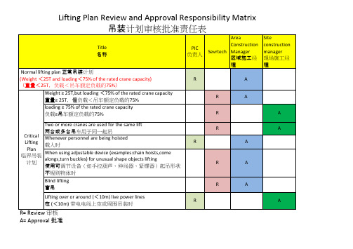
Lifting or Rigging plan
- 格式:xls
- 大小:40.00 KB
- 文档页数:1
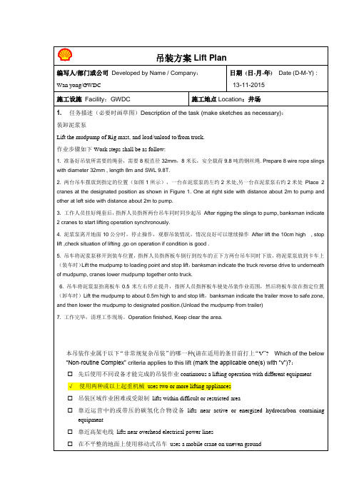
2.起重设备能力校验the verification of the capacity of lifting equipment:吊车的位置position of crane(s)在下方画草图标示吊车位置,被吊物初始和最终的位置,以及吊装过程中吊车工作幅度的变化(注意:在规划吊车位置时,要充分考虑吊装现场的实际空间和被吊物的尺寸大小,以便有足够的工作幅度)make sketch(s) below to illustrate the position of crane(s), and the initial / final positions of the lifted equipment and the change of lifting radius during lifting (note: site space and size of lifted equipment shall be considered to plan the position(s) of crane(s) so as to ensure sufficient lifting radius is available.图1 Figure1吊车受力校验(注意:请使用所选型号吊车的负荷表,并将其附在本吊装方案之后)The verification of the capacity of crane(s) (Note: use the load chart of the crane to be used, and attached the load chart to this lift plan)吊车1 crane No 1规格/ 型号specification / model:QY70K承受的负荷load = 24.33T最大吊装半径时的参数(parameters when at the greatest working radius)工作幅度lifting radius = 6 m(按照最差情况考虑)吊臂长度length of boom = 15.7 m额定负荷rated capacity = 37 T承受的负荷/额定负荷load / rated capacity = 65.76%吊车2 crane No 2规格/ 型号specification / model:QY100K承受的负荷load = 29.74T最大工作幅度时的参数(parameters when at the greatest working radius)工作幅度lifting radius = 6 m吊臂长度length of boom = 17.2 m额定负荷rated capacity = 44 T承受的负荷/额定负荷load / rated capacity = 67.59 %吊索具受力校验The verification of the capacity of lifting accessories在下方画草图以说明吊索具的布置,绑扎方法并计算施加在每个吊索具上的负荷make sketch below to illustrate the arrangement and rigging method of lifting accessories and calculate load applied on each lifting accessory图2 Figure2每台吊车分别用四根直径32mm,8米长,安全载荷9.8吨的钢丝绳与底座两端的指定吊点相连,如图2所示。
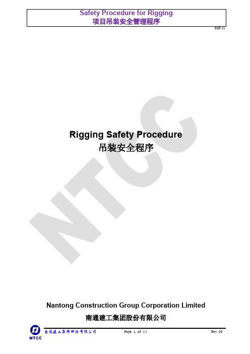


Published in July 2011 by the Workplace Safety and Health Council in collaboration with the Ministry of Manpower.All rights reserved. This publication may not be reproduced or transmitted in any form or by any means, in whole or in part, without prior written permission. The information provided in this publication is accurate as at time of printing.All cases shared in this publication are meant for learning purposes only. The learning points for each case are not exhaustive and should not be taken to encapsulate all the responsibilities and obligations of the user of this publication under the law. The Workplace Safety and Health Council does not accept any liability or responsibility to any party for losses or damage arising from following this publication.This publication is available on theWorkplace Safety and Health Council Website: www.wshc.sgEmail: contact@wshc.sgYear of issue: 2011 First revision: 2014Contents1. Introduction and Background 22. Common Systematic Lapses Involving Lifting Activities 33. Roles and Responsibilities of Lifting Supervisors 44. Common Hazards Associated with Unsecured/ Slippage of Loads 55. Common Hazards Associated with Lifting OperationsInvolving Mobile Cranes 66. Lifting Plans 77. Risk Assessment and Permit-to-Work 88. Statutory Inspection of Lifting Equipment 109. Pre-use Inspection of Lifting Equipment 1110. Selection of Lifting Gears for Lifting Operations 1211. Estimation of Weight of Load 1312. Recommended Rigging and Slinging Methods 1513. Recommended Crane Signals 1814. Annex A: Sample Basic Lifting Plan 1915. Useful References 231. Introduction and BackgroundAccident statistics have shown that fatalities and dangerous occurrences 1 at workplace involving lifting equipment such as cranes has been on an uptrend over the last few years (see Chart 1). Such accidents include failures or toppling of heavy lifting equipment such as cranes during lifting activities, as well as workers being struck by falling or swinging objects while being lifted. From these statistics, there is still much to be done to improve our crane and lifting safety practices at our workplaces. The safe execution of lifting activities is a multi-party effort. Every stakeholder in the value chain (i.e., manufacturers, crane contractors, engineers and designers, project managers, lifting supervisors, operators and workers) has a stake in the lifting operation and must do their part to ensure the safe operation of the lifting work at all times.The role of the lifting team, which comprises the lifting supervisor, crane operator, rigger and signalman, is crucial to ensure safe lifting activities at workplaces. Many of these past accidents had shown that proper planning, co-ordination and supervision of the lifting work could have prevented the accidents and the needless loss of lives. In particular, the role of the lifting supervisor is key especially given the collaborative nature of the work and the importance of ensuring that the various parties are trained and competent, and that they carry out their roles safely and effectively. This Guidebook for Lifting Supervisors is developed to provide greater practical guidance for lifting supervisors to ensure safe supervision of lifting work at the workplace. The Guidebook not only provides guidelines on the roles and responsibilities but also information on common hazards associated with lifting, Lifting Plans, Risk Assessment (RA), Permit-to-Work (PTW) System and Safe Work Procedures (SWP), and recommended rigging and crane signals.Chart 1: Crane-related fatalities and dangerous occurences, 2007-2012.1Dangerous occurrences are incidents involving collapse or failure of a crane, derrick, winch, hoist, piling frame or other appliance used in raising or lowering persons or goods, or any load bearing part thereof (except breakage of chain or rope slings), or the overturning of a crane.2. Common Systemic Lapses Involving Lifting ActivitiesAccidents involving lifting activities occur due to many reasons. However, investigations into such accidents often reveal that the primary causes could be attributed to poor planning, supervision and co-ordination of the lifting operations. Effective implementation of a comprehensive Lifting Plan which comprises comprehensive RA, clear method statement/ SWP , use of suitable lifting equipment, competent lifting team, and PTW system will ensure safe lifting operations at all workplaces. The following is a list of common systemic lapses that often lead to accidents involving lifting activities.• Absence or lack of RA prior to lifting operation.• Lack of implementation of relevant control measures identified in RA.•Absence or lack of proper Lifting Plan for each lifting operation.• Absence or lack of a PTW system to manage the lifting operation.• Failure to adopt a proper rigging method for the lifting operation.• Poor maintenance of lifting equipment (e.g., safety devices, lifting gears).•Poor site control (e.g., failure to maintain a “safe exclusion zone” with barricades/ barriers so that workers not involved in the lifting operation are prohibited from entering the lifting area).3. Roles and Responsibilities of Lifting SupervisorsLifting supervisors appointed for tower or mobile cranes at the worksites must complete the Lifting Supervisors Safety Course conducted by an accredited training provider. They must also have relevant experience in lifting operations for at least one year.The duties and responsibilities of a lifting supervisor include:•co-ordinating and supervising all lifting activities in accordance with the Lifting Plan;•briefing all lifting team members (i.e., crane operators, riggers and signalmen) on the Lifting Plan, risk control measure and safe lifting procedure before the commencement of any lifting operation;•ensuring that only registered crane operators, appointed riggers and appointed signalmen participate in any lifting operation involving the use of mobile and tower cranes;•ensuring that the ground conditions are safe for any lifting operation to be performed by mobile cranes;•be present during all lifting operations; and•if unsafe conditions are reported to him, to take suitable measures to rectify the conditions so that the lifting operation can be conducted safely.Many accidents occurred due to unsecured loads or loads that slipped off during lifting. The following are some common hazards associated with lifting of loads:•defective or damaged lifting gears such as slings,hooks, inserts, eyes, shackles;•improper rigging of loads;•lack of proper receptacles for loose loads such asbricks; or•under capacity of lifting gears.4. Common Hazards Associated withUnsecured/ Slippage of LoadsFigure 1: Defective or damagedcrane hooks.5. Common Hazards Associated with Lifting Operations InvolvingMobile CranesAccidents involving mobile cranes are one of the more common types of crane-related incidents. Many accidents occurred due to either structural failure of the load bearing part of the crane or toppling or collapsing of cranes when they became unstable. The following are some common hazards associated with lifting operations involving mobile cranes.(a) Structural failure of crane component such as the boom, jib, hydraulic rams or wire ropedue to the crane being loaded beyond its loading capacity.(b) The stability of the cranes can be affected by:•poor ground conditions (e.g., unstable ground);•failure to use or fully extend outriggers or stabilisers;•failure to level the crane;•rapid derricking, slewing or manoeuvring;•overloading of cranes;•bypassing of safety devices; or•high wind conditions.(c) Contact or collision due to insufficient safe clearance space between mobile crane andother buildings or structures (e.g., other cranes, overhead power lines, etc).(d) Falling objects as a result of improper securing of loads during lifting operations, orduring erecting or dismantling activities. Falling objects present a risk of injury to workers and the public.The purpose of a Lifting Plan is to facilitate common understanding amongst the lifting team for a safe lifting operation. A typical basic Lifting Plan incorporated with PTW as shown in Annex A is recommended for use at the workplaces. It addresses some key factors affecting safe lifting operations such as:•details of the load;•details of the lifting equipment/ lifting gears used;•means of communications;•personnel involved in the lifting operation;•physical and environmental considerations;•sequence/ special precautions; and•sketch of the zone of operation.Lifting supervisors must brief the lifting team members, which typically consists of the crane operator, rigger and signalmen, on the Lifting Plan before commencement of any lifting operation. The lifting supervisor must stop the lifting operation immediately if it deviates from the Lifting Plan that has been approved by the project manager.6. Lifting Plans7. Risk Assessment and Permit-to-Work ArrayRisk assessment (RA) is the process of evaluating the probability and consequences of injuryor illness arising from exposure to an identified hazard, and determining the appropriate riskcontrol measures. The three basic steps of RA are:1) Hazard IdentificationIdentify the hazards associated with each work activity and the type of potential accidents/incidents that can result from the hazards. Some of the examples of hazards associated withlifting operations are poorly maintained wire ropes, defective safety devices of cranes, improperrigging methods, and so on.2) Risk EvaluationThe process of estimating the risk levels of the identified hazards in terms of the severity of anyinjuries/ damage if an accident were to occur and the likelihood of its occurrence. For example,the risk level of workers working underneath a suspended pre-cast component should beassessed as high risks as the consequences of the load dropping could result in killing theworkers underneath it.2) Risk ControlIdentify appropriate risk control measures to reduce the risk level to an acceptable level. Usingthe last example of a suspended pre-cast component, an appropriate risk control measurewould be the establishment of “safe exclusion zones” to prohibit workers from workingdirectly underneath a suspended load. The exclusion zone should also be demarcated toprevent any unauthorised entry.Permit-to-Work (PTW) System is a system to manage and control certain types of hazardouswork including lifting operations. The contractor’s supervisor co-ordinating the liftingoperation is to apply for the PTW to carry out the lifting operation. In the application for PTW,he should state the scope and conditions in which the lifting operation is to be carried out. Anindependent inspection is then conducted on-site to verify that appropriate control measureshave been taken to mitigate any foreseeable risks. After confirming that the measures haveindeed been taken, the application would then be approved by an authorised person (typicallythe project manager).Lifting supervisors must ensure that a permit is issued by the project manager before heinstructs the lifting team to carry out any lifting operation at the worksite. Table 1 illustrates atypical workflow for the application and approval of a PTW for a lifting operation.Table 1: Workflow for the application and approval of a permit for a lifting operation.8. Statutory Inspection ofLifting EquipmentUnder the WSH (General Provisions) Regulations, lifting equipment such as cranes, lifting appliances and lifting gears shall be inspected by an authorised examiner:•at least once every 12 months; or•at least once every six months for lifting equipment carrying persons.An authorised examiner must also be engaged to inspect the lifting equipment:•after modification or repairs of its load bearing components;•when there is a change in equipment configuration, such as alteration of the boom length or tower crane height; or•after an incident or accident involving the lifting equipment.9. Pre-use Inspection of Lifting Equipment Lifting supervisor must ensure that the crane operator conduct pre-use inspection before eachlifting operation to ensure that the equipment is suitable, safe and correctly installed for thelifting operation. The pre-use checks must include:•visual inspection of the lifting equipment;•functional test of the lifting equipment;•functional test of the safety system and devices; and•functional test of the emergency stop device.Lifting gears must also be inspected to ensure that they are free of any faults or defects before any lifting operation can begin.Lifting supervisor must not allow the lifting operation to be carried out if any defects are spotted during the pre-use checks by the crane operator until all the faults of the cranes are fully rectified. Similarly, lifting gears must not be used if defects are spotted and reported by the riggers.Factors affecting the choice of lifting gear for each lifting operation are:• weight and type of load;• available lifting points;•position of the centre of gravity of load;• mode of use (See Table 2 for a sample chart of Mode Factors which lists the appropriatetypes of sling and methods of securing loads to slings.); and •environment factors (e.g., wind speed conditions).10. Selection of Lifting Gears for Lifting OperationsTable 2: A sample Mode Factors chart.11. Estimation of Weight of LoadThe following may be used as a general guidance to estimate the weight of load going to be lifted in the lifting operation.• Check if the weight is marked on the load.• Check if the weight is indicated on any documentation (e.g., shipping documents).• Check if the weight is indicated on the construction drawing of the load.•If the load is still on a trailer or truck, weigh it physically over a bridge.• Estimate the weight using Table 3 or the formulae in Figure 2 (note that factors such assite conditions, water content, decomposition, irregular shapes and residues in vessels can affect the accuracy of load weight to be estimated).1,000 kgs = 1 tonTable 3: Average weight of various materials.Figure 2: Volumes of common shapes.12. Recommended Rigging andSlinging MethodsThe Included Angle of Slings• It is important to be aware of the increased loadings on the slings when lifting at larger included angles or smaller sling angles. For rigging configurations with two-legged slings, the included angle should not exceed 90° as this will reduce the SWL of the slings.• The slings must sit in the base of the hook and be clear of the latch to prevent fouling of the latch.Rig to the Centre of Gravity (C.G.)Figure 4: Good load control starts with rigging the load to the centre of gravity directly below the load hook.Figure 3: The working load limit is valid for a single leg or multiple legs.Hinge Points Chain SlingsFigure 5: Use a single master link for a single and two-legged chain slings.Figure 6: Use a master link with sub-links forthree- or four-legged chain slings. Hinge Points Wire Rope and Synthetic SlingsFigure 7: Use a single master link instead of placing wire rope slings directly on the load hook.Figure 8: Use a master link with sub-links forall three- or four-legged wire rope slings.Figure 9: Prevent fouling of safety latchon load. Sling in base of hook.Fouling of LatchFigure 10:Sling fouled on latch. Connection of Slings to ShacklesFigure 12: Use a shackle that is large enoughto prevent pinching of the synthetic slings. Figure 11: Use a shackle with diametergreater than wire rope diameter if there is nothimble in the eye.161713. Recommended Crane SignalsFigure 13: Recommended crane signals.14. Annex A: Sample Basic Lifting Plan Sample Basic Lifting Plan181920212223• Code of Practice on Safe Lifting Operation in the Workplace, First revision 2013.• SS536: 2008 Code of Practice for the Safe Use of Mobile Cranes.• SS559: 2010 Code of Practice for the Safe Use of Tower Cranes.• SS343 – Part 1: 2001 Specification for Lifting Gear – Wire Rope Slings.• SS343 – Part 2: 1989 Specification for Lifting Gear – Hooks.•SS343 – Part 3: 1990 Specification for Lifting Gear – Shackles.• SS497: 2002 Specification for Design, Safe Use and Maintenance of Overhead Travelling Cranes.• Lifting Equipment - A User’s Pocket Guide published by LEEA, UK.• The Lifting Engineers Handbook published by LEEA, UK.• Best Rigging Practices by Crosby Group Inc.• Worker’s Safety Handbook for Crane Operator, 2011.• Worker’s Safety Handbook for Rigger and Signalman, 2011.•Worker’s Safety Handbook for Lorry Crane Operator, 2012.15. Useful ReferencesNote:1. This is only a sample Lifting Plan, the content is by no means comprehensive. Users would have toinclude key critical document and information such as load capacity chart, range diagram, rigging method, sling angle, etc to ensure safe lifting operations. 2. Further guidance can be obtained from the following collaterals:• Guidebook for Lifting Supervisors • Worker’s Handbook for Crane Operator •Worker’s Handbook for Rigger and SignalmanThis page is meant to be blank This page is meant to be blank2425This page is meant to be blank26。
1-877-MAX-LIFTGTC-20001-877-MAX-LIFTMarch 2022. Unless otherwise specified, all information in this brochure refers to a standard crane equipment, and it is intended as general information only. No liability is assumed. Errors reserved. Product specifications and prices are subject to changes without notice. The p hotographs and/or drawings in this brochure are for illustrative purposes only. For correct and safe crane operation, the original operating manual and lifting capacity charts are essential. Failure to follow the corresponding Operator’s Manual when using our equipment or f ailure to otherwise act responsibly may result in property damage, serious injury or death. The sole warranty applicable with respect to oure quipment is the standard warranty as per general terms and conditions of sales and service (ask your local Tadano dealer for details), and Tadano makes no other warranty, express or implied. All rights reserved. Any use of the trademarks, logos, brand names and model names used herein is prohibited.© Tadano Ltd. 20222 | GTC-2000Contents7 Specifications (8)9 Transportation...............................................................................................................................10-12 Transport variants .. (13)15 Speeds and gradeability (16)Main boom (17)Slewing (17)Hoist (17)Hook Blocks (17)HA: Main boom .............................................................................................................................18-53 HAV: Folding swing-away jib ..............................................................................................................54-121 HAV-HY: Hydraulic swing-away jib .......................................................................................................122-188 Notes to Lifting Capacity . (189)191 Basic machine ..............................................................................................................................192-193 Optional Equipment (non-exhaustive) . (194)GTC-2000| 34 | GTC-2000 CounterweightT rackR adiusM ain boomF olding swing-away jibH ydraulic swing-away jibR oll/list angleW ind speed in ft /s (feet per second)T rack shoeH ook blockH oist 1H oist 2T ravel speedG radeabilityS lewingB oom telescoping B oom elevationW orking speedsM ax. line pull R ope diameter R ope length H ook block (capacity-sheaves-rope diameter) N umber of lines P ossible load of hook block N umber of sheaves in boom head D istance head sheave axle – hook ground W eight of hook blockGTC-2000 | 5T rack leftT rack rightE xtension beamB ase craneC entral ballastT ruck pay loadC ounterweight base plateC ounterweight plateA ssembly weightT ransport variantHighlights196.9 ft pinned boom; 16.4 ft to 75.5 ft jib (tiltable from 0° to 36°)Lifting capacities up to 4° roll/list angle, all …Pick & Carry“, jib capacities up to 1° roll/list angle Double hook operation with rooster sheave or jibPowerful hoists with 1.02 in. rope (30,640 lb pull / 456 ft/min. speed)Powerful, robust and versatile undercarriage with smart and comprehensive access concept Fully self rigging operationRemote control for all rigging and operating functionsBest in class traction force (326,000 lbf)6 | GTC-2000Specifications8 | GTC-2000Transportation* 107,990 lb with Hyd Jib / 107,660 lb with Mech Jib10 | GTC-2000GTC-2000| 1140,800 lb*12 | GTC-2000* Hydraulic version1,010 lb1,900 lb 1,040 lb 1,650 lb / 1,980 lb*5,070 lb16,540 lb16,540 lb1 x 11,025 lb4 x 22,050 lb** 2-bar shoeGTC-2000| 13Notes14 | GTC-200016 | GTC-2000GTC-2000 | 17* Heavy lift sheave required** Heavy lift sheave and 7 sheaves hook block requiredHook BlocksSlewing1,6 rpm18 | GTC-2000+ 33,100 lb**Heavy lift sheave and 7 sheaves hook block required*** Max. crane capacity – with additional special equipment**** over front/rear1)C apacities with horizontal boomGTC-2000| 19+ 33,100 lb126.0 ft20 | GTC-2000+ 33,100 lb**Heavy lift sheave and 7 sheaves hook block required 1)C apacities with horizontal boom+ 33,100 lb126.0 ft+ 33,100 lb**Heavy lift sheave and 7 sheaves hook block required 1)C apacities with horizontal boom+ 33,100 lb126.0 ft+ 33,100 lb**Heavy lift sheave and 7 sheaves hook block required 1)C apacities with horizontal boom+ 33,100 lb126.0 ft+ 33,100 lb**Heavy lift sheave and 7 sheaves hook block required 1)C apacities with horizontal boom+ 33,100 lb126.0 ft+ 33,100 lb1)C apacities with horizontal boom+ 33,100 lb+ 33,100 lb**Heavy lift sheave and 7 sheaves hook block required 1)C apacities with horizontal boom+ 33,100 lb126.0 ft+ 33,100 lb1)C apacities with horizontal boom+ 33,100 lb126.0 ft+ 33,100 lb1)C apacities with horizontal boom+ 33,100 lb126.0 ft+ 33,100 lb1)C apacities with horizontal boom+ 33,100 lb126.0 ft+ 33,100 lb1)C apacities with horizontal boom+ 33,100 lb126.0 ft+ 33,100 lb+ 33,100 lb+ 33,100 lb+ 33,100 lb126.0 ft+ 33,100 lb+ 33,100 lb126.0 ft+ 33,100 lb+ 33,100 lb126.0 ft+ 33,100 lb+ 33,100 lb126.0 ft。
16.2、Lifting plan吊装方案I、Generals of Work工程概况There are 248 sets of equipment with different weights. Lifting of large equipments concerned is mainly concentrated in Production Building B, Mixing Pots T-202, T-210 are the heaviest equipments, with monomer weight of 27 tons. 120T Truck Crane Model ATF 120-5 shall be employed. 100T, 50T, 25T cranes may be used according to different volumes and weights respectively and forklift and chain blocks plus roller bars will also be used to locate equipment in place. The manufacturer shall be responsible for transporting equipment to the site of Ecolab Taicang Jade Project. The authorized party shall be responsible for mobilization of vehicle and personnel and coordination and communication with the Owner at site. We will pay highly attention to construction and get organized elaborately, arranged thoughtfully, work done carefully to ensure the lifting of equipment in place without any risks.本项目共有设备248台,设备重量不等,涉及的大型设备吊装主要集中在生产车间B,其中以混合釜T-202、T210为最重,单重为27吨。