SIMCO HBA离子风枪产品介绍
- 格式:pdf
- 大小:753.83 KB
- 文档页数:3

1.2. 3.5. ■作用原理 1. ・产品特点 2. ・技术参数 3. 6悬挂式风机 4. ■作用原理 5. ・产品特点 1. ・产品用途 2. ・技术参数 3. ・灭菌原理 4. ・注意事项 5. 7保养方案离子风机编辑锁定离子风机的主要作用是除静电,具有出众的除静电性能,防止静电污染及破坏。
是电子生产线,维修台等个人型静电防护区域的理想设备。
是专为局部区域而设计的。
具有体积小,重量轻,安装方便等特点。
可采用积木式安装,适用于各种场所。
一般离子风机可分为台式离子风机,卧式离子风机,悬挂式离子风机,微型离子风机。
中文名离子风机外文名IONIZINGBLOWER供电电压220V目录1. 1产品简介2. 2主要指标3. 3作用原理4.4电离器件离子风机产品简介编辑4.・产品特点 ■产品用途 ・技术参数5卧式离子风机静电消除器是将电离了的空气输送到较远的地方去消除静电的一种静电消电器。
其主要由电晕放电器、高压电源和送风系统组成。
离子风机静电消除器是将电离了的空气输送到较远的地方去消除静电的一种静电消电器。
其主要由电晕放电器、高压电源和送风系统组成。
它是根据尖端放电和正负电“中和”原理设计制造的。
它可消除绝缘材料及物品上的静电。
离子风机静电消电器风量大小可以调节,使得消电空间范围更大。
离子风机主要指标编辑静电中和速率:>400V/s作用距离:0.3〜0.8m消电效率优于98%电源功率<30W,连续工作;臭氧浓度v0.003ppm离子风机作用原理编辑台式离子风机,离子风机能够在各种工作环境中(包括净化室)提供大范围的除静电区域、快速的除静电时间和稳定的离子平衡电压。
台式离子风机可产生大量的带有正负电荷的气流,可以将物体上所带的电荷中和掉。
当物体表面所带电荷为负电荷时,它会吸引气流中的正电荷;当物体表面所带电荷为正电荷时,它会吸引气流中的负电荷。
等量正负电荷接触时,即可达到电性中和。
离子风机离子风机电离器件编辑电离器件在高压发生器产生的低电流高电压作用下,形成一个稳定的高强电场,电离空气形成离子体,由气流带出到达物体表面,达到中和静电和除尘目的。

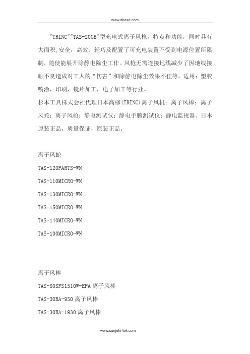
"TRINC""TAS-20GB"型充电式离子风枪,特点和功能,同时具有大面积,安全,高效、轻巧及配置了可充电装置不受到电源位置所限制,随使能展开除静电除尘工作。
风枪无需连接地线减少了因地线接触不良造成对工人的“伤害”和除静电除尘效果不佳等,适用;塑胶喷涂,印刷,镜片加工,电子加工等行业。
杉本工具株式会社代理日本高柳(TRINC)离子风机;离子风棒;离子风蛇;离子风枪;静电测试仪;静电手腕测试仪;静电监视器。
日本原装正品,质量保证,原装正品。
离子风蛇TAS-120PARTS-WNTAS-110MICRO-WNTAS-130MICRO-WNTAS-150MICRO-WNTAS-140MICRO-WNTAS-100MICRO-WN离子风棒TAS-80SFS1510W-EPA离子风棒TAS-30BA-950离子风棒TAS-30BA-1930离子风棒TAS-31 BA离子风棒TAS-30BA-1510离子风棒TAS-30BA-390离子风棒TAS-301BA离子风棒TAS-801SFS离子风棒TAS-801SFS离子风棒;静电测试仪TAS-160MONS静电测试仪TAS-161MONS静电测试仪TAS-162MONS静电测试仪TAS-1630MONS静电测试仪TAS-164MONS静电测试仪TAS-165MONS静电测试仪TAS-166MONS静电测试仪离子风枪TAS-100BL-16-0400离子风枪TAS-140POWDER离子风枪AS-20GL离子风枪TAS-20GB离子风枪TAS-20GL-EPA离子风枪离子风机型号TAS-02C离子风机TAS-183CUTE离子风机TAS-130SBC离子风机TAS-500离子风机DIT离子风机TAS-181离子风机TAS-04D离子风机TAS-201WAGON离子风机TAS-182NWM离子风机TAS-182-C离子风机TAS-502DIF离子风机如有需要请联系我们杉本。


SIMCO进口风机,风枪,风棒等产品详细资料另看日本SIMCO系列西姆卡风机系列:卧式离子风机悬挂式三孔离子风机台式离子风机悬挂式双孔离子风机等多孔离子风机西姆卡风枪系列:TOP GUN 离子风枪SC-004 离子风枪SC-004H大头离子风枪西姆卡静电棒系列:SC-040离子风铝棒卧式离子风机,西姆卡防静电设备卧式离子风机是一种大风量,宽范围的离子消除器。
中和时间快,离子风覆盖面积大,特别适用于电子,塑胶等行业。
风量可在70---120CFM范围内调节,离子平衡电压为0V+/-10V.特点:本身固有的平衡功能;风速连续可调;交流技术,离子发生指示;应用:医药设备制造;电子组装生产线;微电子制造等行业Specification(技术参数)Decay Tdst Results(测试结果)备注:1.测试距离单位为毫米,中和时间单位为秒。
2.测试数据以用FMX-003静电测试仪测试结果为准。
3.测试的数据会因测试时的环境空气温湿度而有所变化西姆卡三头悬挂式离子风机,可提供平衡离子气流的、宽范围集中区域的离子消除器。
可消除或中和宽范围集中目标或不易接触区域的静电荷。
是精密电子产品,电子组装,医药制造组装,包装和细小产品成型的理想的静电消除器。
特点:本身固有的平衡功能;三束离子风输出;风速连续可调;交流技术,离子发生指示;可加装加热器和灯光照明;应用:医药设备制造;电子组装生产线;微电子制造等行业;Specification(技术参数)Decay Tdst Results(测试结果)备注:1.测试距离单位为毫米,中和时间单位为秒。
2.测试数据以用FMX-003静电测试仪测试结果为准。
3.测试的数据会因测试时的环境空气温湿度而有所变化西姆卡单头台式离子风机,可提供平衡离子气流的、宽范围集中区域的离子消除器。
可消除或中和宽范围集中目标或不易接触区域的静电荷。
是精密电子产品,电子组装,医药制造组装,包装和细小产品成型的理想的静电消除器。

ShakmatDual Dagger6HP Eurorack Module Built & designed in PAN LP PAN HPThe Dual Dagger is a double-sided weapon, carefully sharpened to chop stereo signals. The module gives independent control over low-pass and high-pass cutoff frequencies, and an assignable resonance is shared on one control. The Linkfunction turns the dual filter into a band-pass filter, with control over frequency, bandwidth and band edges resonance! The module is carefully calibrated to share the exact same parame-ters on both audio channels and thanks to the pan function, it is easy to break up the cutoff frequencies of each side up, which leads to a whole new territory of stereo treatments!IntroductionThe Dual Dagger requires a standard 2x5 pin eurorack power cable. Make sure the red stripe on the cable matches the -12V side of the Dual Dagger power header.InstallationLow-pass potentiometer Link switchResonance potentiometer High-pass resonance switch Low-pass resonance switch High-pass potentiometerLow-pass CV input Resonance CV input High-pass CV input Pan CV inputs Inputs OutputsBasicsDespite its little size, the Dual Dagger contains four differentanalogue filters: two low-pass and two high-pass filters, all with a -24dB/octave slope. The LPF potentiometer [A] and CV input [1] control the cutoff frequency of the two low-pass filters. The HPF potentiometer [F] and CV input [3] control the cutoff frequency of the two high-pass filters.The Resonance potentiometer [C] and CV input [2] control the low-pass filters resonances if the low-pass resonance switch [D] is engaged. When the high-pass resonance switch [E] is engaged, the Resonance potentiometer controls the high-pass filters’ resonance. When both resonance switches are engaged, the resonance is affecting both the high and low-pass.Fig. 01 — Dual Dagger simplified architectureHPF1IN1IN2OUT1OUT2LPF1HPF2LPF2HPF Freq.(Pot. and CV input)HPF Res.Resonance(Pot. and CV input)LPF Res.Audio PathLPF Freq.(Pot. and CV input)Frequency controlResonance controlLink switchThe Link switch [B] turns the module into a powerful 8th order stereo bandpass filter with CV control over frequency and bandwidth. When engaged, the Link function makes the low-pass filters follow the high-pass filters. Therefore, the control of the high-pass moves the four filters and the low-pass control only affects the low-pass section. In a bandpass perspective,high-pass control is now the bandpass (lowest) frequency and the low-pass control is the filter’s bandwidth. Resonance still acts selectively on the high-pass edge and/or the low-pass edge according to the switches.Fig. 02 — Bandpass filtering with Link switch engagedLevelFrequencyLevelFrequencyLevelFrequencyThe Dual Dagger has CV inputs that allow to diffirentiate the cutoff frequencies of each channel, leading to a whole new territory of stereo effects. When a positive voltage is received in the Pan inputs [4], the corresponding filter cutoff frequency of the firstchannel increases as the second one decreases. In short, sending a positive voltage in the PAN LP input will cause the left filter to open and the right filter to close.When a negative voltage is received, the first channel filter cutoff frequency decreases as the second channel filter cutoff frequency increases. It is of course possible to combine the use of Pan inputs with the Link function and thus creating great stereo bandpass filtering effects!PanningThe jumper on the back of the module allows to set the resonance potentiometer range. In "Lo" position the range is limited, avoiding the filter to self-oscillate. In "Hi" position the resonance can go much higher, allowing self-oscillation.JumperLevelFrequencyLPF 1LPF 2LevelFrequencyFig. 03 — Positive voltage sent to PAN LPBesides all obvious stereo treatment and filtering, the Dual Dagger can used in many creative ways, here are some ideas.Patch ideasWe know a sinewave can be easily turned into a kick drum sound when being FMed by a decaying envelope. Based on that, the Dual Dagger leads to a wide range of kick drums : mix both outputs and use the pan input to detune sections, try with both sections set to be highly resonant, use the resonance input instead of a VCA,...Kick DrumUse a mono source and mix both outputs, you now have a double peak high pass and low pass filter - with resonance engaged, use the pan inputs to control the "distance" between two resonant peaks!Summing OutputsWhile using only one channel, use the high pass section as a sine wave VCO tracking V/Oct over a few octaves (resonance at max will cause the filter to self-oscillate). In order to create more complex waveforms, use the second channel to fm the PANhp. Now that you have a lot of harmonics, the low pass section will be handy to smooth out the harsh timbre. Another trick is to mix both channels and to use the PANhp as a "detune" parameter between the two sine VCOs.Simple VoiceOur SumDif module is a great companion for this filter as it allows to convert left right stereo to mid side stereo ! Combined with the Dual Dagger you can explore peculiar panning effects while using the pan section which will offset the cut off frequency of the centre signal from the side signal.LR & MSSpecificationsSize 6 HP Depth 29 mm Audio Inputs -5 to 5V Current Draw 65 mA @ +12V 80 mA @ -12V。
- For the application of architectural paints and coatings -The following Warnings are for the setup, use, grounding, maintenance and repair of this equipment. The exclamation point symbol alerts you to a general warning and hazard symbols refer to procedure-specific risks. Refer back to these Warnings. Additional, product-specific warnings may be found throughout the body of this manual where applicable.SKIN INJECTION HAZARDHigh-pressure fluid from gun, hose leaks, or ruptured components will pierce skin. This may look like just acut, but it is a serious injury that can result in amputation. Get immediate surgical treatment.•Do not point gun at anyone or at any part of the body.•Do not put your hand over the spray tip.•Do not stop or deflect leaks with your hand, body, glove, or rag.•Do not spray without tip guard and trigger guard installed.•Engage trigger lock when not spraying.•Follow Pressure Relief Procedure in this manual, when you stop spraying and before cleaning, checking, or ser-vicing equipment .FIRE AND EXPLOSION HAZARDFlammable fumes, such as solvent and paint fumes, in work area can ignite or explode. To help prevent fire and explosion:•Use equipment only in well ventilated area.•Eliminate all ignition sources; such as pilot lights, ciga-rettes, portable electric lamps, and plastic drop cloths (potential static arc).•Keep work area free of debris, including solvent, rags and gasoline.•Do not plug or unplug power cords, or turn power or light switches on or off when flammable fumes are present.•Ground all equipment in the work area. See Grounding instructions.•Use only grounded hoses.•Hold gun firmly to side of grounded pail when triggering into pail.•If there is static sparking or you feel a shock, stop oper-ation immediately. Do not use equipment until you identify and correct the problem.•Keep a working fire extinguisher in the work area.EQUIPMENT MISUSE HAZARDMisuse can cause death or serious injury.•Do not operate the unit when fatigued or under the influ-ence of drugs or alcohol.•Do not exceed the maximum working pressure or tem-perature rating of the lowest rated system component. See Technical Data in all equipment manuals.•Use fluids and solvents that are compatible with equip-ment wetted parts. See Technical Data in all equipment manuals. Read fluid and solvent manufacturer’s warn-ings. For complete information about your material, request MSDS forms from distributor or retailer.•Check equipment daily. Repair or replace worn or dam-aged parts immediately with genuine manufacturer’s replacement parts only.•Do not alter or modify equipment.•Use equipment only for its intended purpose. Call your distributor for information.•Route hoses and cables away from traffic areas, sharp edges, moving parts, and hot surfaces.•Do not kink or over bend hoses or use hoses to pull equipment.•Keep children and animals away from work area.•Comply with all applicable safety regulations.PRESSURIZED ALUMINUM PARTS HAZARD Do not use 1,1,1-trichloroethane, methylene chlo-ride, other halogenated hydrocarbon solvents or flu-ids containing such solvents in pressurized aluminumequipment. Such use can cause serious chemical reaction and equipment rupture, and result in death, serious injury, and property damage.PERSONAL PROTECTIVE EQUIPMENTYou must wear appropriate protective equipment when operating, servicing, or in the operating area of the equipment to help protect you from serious injury. This equipment includes but is not limited to:•Protective eyewear•Clothing and respirator as recommended by the fluid and solvent manufacturer •Gloves•Hearing protectionWARNINGS312830MI n s t r u c t i o n s /P a r t s2312830MPressure Relief ProcedureFollow this Pressure Relief Procedure whenever instructed to relieve pressure, stop spraying, check or service equipment, or install or clean spray tip.1.Turn OFF power and turn sprayer pressure control to low-est pressure setting.2.Hold gun against side of flushing pail. Trigger gun into pail to relieve pressure.If you suspect spray tip or hose is clogged or that pressure has not been fully relieved after following the steps above, VERY SLOWLY loosen tip guard retaining nut or hose end coupling to relieve pressure gradually, then loosen completely. Clear hose or tip obstruction.Gun Trigger LockTo prevent injury when the gun is not in use, always set the gun’s trigger lock if unit is being shut down or left unattended.SetupMake sure sprayer is turned off and unplugged from powersource. Refer to your sprayer instruction manual for priming and spray instructions.Connect Gun to Sprayer1.Attach supply hose to sprayer fluid outlet.2.Attach other end of supply hose to gun swivel (5). Use two wrenches (one on the swivel (5) and one on the hose), totighten all connections securely.3.Refer to sprayer instruction manual for priming instructions.Installing Tip (26) and Guard (25) on Gun1.If equipment has recently been operated, relieve pressure . Set trigger lock.ing a pencil or similar object, insert seal(24) into back of guard (25).3.Install guard (25) over end of gun (1).4.Insert tip (26) in guard (25). Tighten retaining nut.OperationSpraying1.Unlock trigger lock.2.Be sure the arrow shaped tip (26) faces forward (spray).3.Hold gun perpendicular and approximately 12-inches (30 cm) from surface. Move gun first, then pull gun trigger (3) to spray a test pattern.4.Slowly increase pump pressure until coverage is uniform and even (see sprayer instruction manual for additional information).Aligning Spray1.Relieve pressure . Set trigger lock.2.Loosen guard retaining nut.3.Align guard (25) horizontally tospray a horizontal pattern.4.Align guard (25)vertically to spray a vertical pattern.Clearing Clogs1.Relieve pressure . Set trigger lock.2.Rotate tip (26) 180°. Unlock trigger lock. Trigger gun into pail or onto ground to remove clog.3.Set trigger lock. Rotate tip (26) 180° back to spray position.CleanupFlush gun after each work shift and store in a dry location. Do not leave the gun or any parts in water or cleaning solvents.WARNINGWARNINGWARNINGTrigger LockedTrigger Unlocked(spray)ti11308aWARNINGWARNINGWARNING(4) Vertical(3) Horizontal ti11564a ti11563a312830M 3Parts1c *Kit 288817 repairs both series A and B guns.1a replaces these three components of series A.Ref.Part DescriptionQty.1288817KIT, repair, gun (includes 1a, 1b, 1c)11a SEAT, valve 11b NEEDLE, gun11c 131477NUT, lock13243639TRIGGER, repair kitincludes 10, 32, 334195495GUARD, trigger 15238817KIT, swivel1195384ADAPTER, gun inlet (SG2)16 288749FILTER, gun 1CAN085FILTER, gun 17 179733SEAL, sleeve 18195395CAP, end110115484PIN, actuator222113409RETAINER, guard 123195393HANDLE, gun (SG2)1195788HANDLE, gun (SG3, SG3-E)1195920HANDLE, gun (SG3-A)124115485O-RING12617R014HOUSING, fluid 132177538STUD, trigger 133131476NUT, lock, hex 1Replacement Warning labels, tags and cards are available at no cost.Keep these spare parts on hand to reduce down timeRef.Part Description Qty.Ref Part Description Qty 24243004Single seal TRU 1CAN004Single seal TRU1243281OneSeal ™, RAC 5 (5-pack)1246453OneSeal ™, RAC X (5-pack)117P501KIT, gasket, FFLP, LP (5-pack)125237859GUARD, TRU 1CAN001GUARD, TRU 1243161GUARD, RAC 51246215GUARD, RAC X and LP 226TRU515TIP, spray 515, TRU 1CAN515TIP, spray 515, TRU 1286515TIP, spray 515, RAC 51LTX515TIP, spray 515, RAC X 1TRU517TIP, spray 517, TRU 1CAN517TIP, spray 517, TRU 1262515TIP, spray 515, RAC 51LP519TIP, spray, 519, LP 1For complete warranty information contact your local Graco distributor, call Graco customer service:1-800-690-2894 or visit our website: .All written and visual data contained in this document reflects the latest product information available at the time of publication.Graco reserves the right to make changes at any time without notice.For patent information, see /patents.Original instructions. This manual contains English. MM 312830Graco Headquarters: MinneapolisInternational Offices: Belgium, China, Japan, KoreaGRACO INC. AND SUBSIDIARIES • P.O. BOX 1441 • MINNEAPOLIS MN 55440-1441 • USA Copyright 2008, Graco Inc. All Graco manufacturing locations are registered to ISO 9001. Revised M, August 2020MaintenanceBefore performing any maintenance on gun, read all warnings on frontcover of this manual and relieve pressure .Cleaning/Replacing Filter (6)1.Relieve pressure . Set trigger lock2.Disconnect fluid hose from gun at swivel (5).3.Disconnect trigger guard (4) from guard retainer (22).4.Unscrew handle (23) from gun (1).5.Remove filter (6) through top of handle (23).6.Clean filter (6). Use a soft brush to loosen and remove excess debris.7.Insert clean filter (6) into handle (23).8.Reattach handle (23) to gun (1). Tighten securely.9.Reconnect trigger guard (4) to guard retainer (22).Translated ManualsRepairReplacing Needle1.Relieve pressure . Set trigger lock.2.Remove tip (26) and guard (25) from gun (1).3.Disconnect fluid hose from gun at swivel (5).4.Squeeze trigger while unscrewing diffuser.5.Remove locknut and end cap.6.Tap out needle.e a soft brush to clean out internal passages of gun.8.Grease o-rings of new needle using a non-silicon grease.9.Guide new needle (15b) through front of gun .10.Install end cap and locknut, loosely.11.For needle housing (15a), apply medium strength (blue) threadsealant to threads.12.Squeeze trigger while installing needle housing. Torque to 26-32 ft-lb (35-43 N•m).13.Hold gun with nozzle facing up.14.Set trigger lock.15.Turn locknut (a) clockwise until you see and feel trigger (3) raise slightly.16.Turn locknut (a) 3/4 turn counter-clockwise.NOTE: When needle is properly adjusted, trigger will move freely.17.Connect fluid hose. Install tip (26) and guard (25).18.Prime sprayer. See sprayer instruction manual.19.Trigger gun into bucket until fluid flows from gun.20.Release trigger (3). Fluid flow should stop immediately.21.Set trigger lock.22.Aim gun into bucket. Trigger gun. No fluid should flow.23.If the gun fails tests, steps 19 and/or 21, relieve pressure and disconnect hose. Readjust needle. Repeat tests.Technical DataWARNINGFrench - 312831Estonian - 312845Spanish - 312832Latvian - 312846Dutch - 312833Lithuanian - 312847German - 312834Polish - 312848Italian - 312835Hungarian - 312849Turkish - 312836Czech - 312850Greek - 312837Slovakian - 312851Croatian - 312838Slovenian - 312852Portuguese - 312839Romanian - 312853Danish - 312840Bulgarian - 312854Finnish - 312841Chinese - 312855Swedish - 312842Japanese - 312856Norwegian - 312843Korean - 312857Russian - 312844WARNINGMaximum working pressure 3600 psi (248 bar, 24.8 MPa)Fluid orifice size 0.125 in. (3.18 mm)Weight (with tip and guard)22 oz. (630 g)InletMaximum material temperature 120 F (49 C)Wetted Parts Stainless steel, polyurethane, nylon, aluminum, tungsten carbide, brass *Noise Level: Sound power 87 dBaSound pressure 78 dBa*Measured at 3.1 ft (1m) while spraying water-based paint, specific gravity 1.36, through a 517 tip at 3000 psi (207 bar, 20.7 MPa) per ISO 3744Translated manuals can be requested through a distributor or at .。
思美高SIMCOFMX-004静电场测试仪使用说明书思美高SIMCO FMX-004静电场测试仪使用说明书思美高SIMCO FMX-004静电场测试仪使用说明书是一种手持式静电测试仪器,采用的震动电容感应技术,使仪器体积小,重量轻。
采用四个按钮结构,操作简便,容易掌握。
本静电测试仪*大量程为30KV(30,000)测试结果为2时,显示一条竖条,POWER开/关机;ZERO调仪器归零;MODE为测试模式选择;HOLT按钮锁定读数,并保持测试结果在LCD上。
仪器前端设有两个LED,用来帮助测试人员保持测试仪器跟测试目标之间的距离。
但当测试空气中离子的平衡度时,这两个灯是不亮的。
由于本仪器采用导电材料制作,所以有很强的抗干扰的能力思美高SIMCO FMX-004静电场测试仪使用说明书功能特点:*容易读数,操作简便*轻巧的设计*测试范围宽,重复测试精度高*自动量程转换30KV(30,000)(距离25mm)*数字和竖条同时显示*五分种自动关机功能*四种测量模式(AUTO(自动),Hi(高量程),Low(低量程),Ionblance(离子平衡))具体参数测范围: 0.00--3.00kV(Low低量程)0.0--30.0KV(Hi高量程)0--300V(Ion离子平衡度测试)0—30KV(AUTO自动模式)测量距离:25mm0.5mm两LED作为测量参考。
距离为仪器到测试目标之间的距离。
响应时间:,1s测量精度:10%LCD刷新速度:5次/秒工作条件:10Cº-40Cº,0-60%RH显示特性:两边竖条显示。
蓝的是显示负电,红的显示正电。
竖条显示精度:低测量范围时0.1KV,高测量范围时1.5KV,测量离子平衡时15V。
数显读数:AUTO(自动模式)X.XX=0.001.49KV(低量程)XX.X=1.0KV-30.0KV(高量程)Hi(高量程)X.X=0.0-30.0kVLow(低量程) X.XX=0.00-3.00kV离子平衡模式时显示(IB)XXX=0-300V模拟电压输出:AUTO 3.00V(2.0KV=0.2V)HI 3.00V(1.0KV=0.10V)LOW 3.00V(2.0KV=0.2V)Ionblance 3.00V(200KV=2.00V)蜂鸣器响声特点:在下列情况下能听到蜂鸣器响声开机:滴一声响自动关机:无任何操作时五分钟自动关机响三次,每次两声超出测量范围时:发出连续的叫声自动关机功能:本机无操作时,五分钟自动关机,节省电池使用电源:9V方型电池电池寿命:30小时外型尺寸:123(MM)×73(MM)×25(MM)重量:170g思美高SIMCO FMX-004静电场测试仪使用说明书各功能的操作,使用FMX-004使用9V方型电池,电池寿命大概30小时,当机器打开的时候,会有电池电量指示(如下图所示)注*图中黑色部分表示电量电池的更换:1,打开机器后面的电池盖。
基恩士sj离子风棒说明书基恩士(Inno-Technology)是一家日本的研发、生产、销售及服务于全球医疗器械行业的公司。
基恩士(Sinno-Technology)总部位于日本新潟县,在中国、韩国等国家均设有分公司。
自199年成立以来,基恩士始终致力于开发全球市场,凭借卓越的品质和技术,在世界各地拥有数百家销售服务机构。
而基恩士Sinno-Technology还是一个“具有高创新能力、具有全球竞争力和持久竞争力的中国企业”。
1.使用前将样品放在干燥的环境中,然后在距离样品1 cm 处进行测量;在风管内部放置一支长为2 cm左右的电,接上充电电源。
根据使用说明定期进行清洗,确保无杂质。
使用后将电容量表取下,将样品放入回风口(温度为60℃左右)。
电底部将离子线绕成螺旋状;使用前将电移至远离吹风口处。
2.如果样品的湿度较大,请使用本仪器,然后再检查是否有干燥的现象,如果发现该现象,请及时清除;如果发现湿度过大,请使用本仪器,然后再检查是否有干燥的现象,如果发现该现象,请及时清除;如需再次使用本仪器,请重复上述步骤。
本仪器一般使用干燥的软纸盒包装,如果打开后,有水珠或滴水现象,请立即用水冲洗干净;如使用蒸馏水或纯净水,请按下“样品”键;如在使用纯净水时,有水珠滴落的现象,可用棉签擦拭干净;如样品中有水珠、液体或其他物质时,请先用棉签擦干净,然后再用纯净水冲洗干净和干燥。
3.在距离样品1 cm处测量的温度通常不会超过100℃,因此使用本仪器时应将室温保持在40℃左右;如果需要将样品放置在离子风中进行测量,则应保证距离样品1 cm处没有其他物体的干扰。
而基恩士公司作为世界上最早进行离子风棒研发的企业之一,一直以来都在为用户提供优质的产品。
对于新产品的研发,基恩士公司也一直保持着高标准的态度和方法。
除此之外,为了确保基恩士公司在离子风棒领域内所具备的优势与经验,在过去数年中基恩士Sinno-Technology一直积极和其他地区之间进行着息交流。
SIMCO HBA 离子离子风枪产品介绍风枪产品介绍风枪产品介绍::
SIMCO HBA 离子风枪具有通用的除尘、除静电效果。
可用于电讯制造、电子、半导体、医用设备制造等工厂生产线、设备和常用工具的静电防护中。
SIMCO HBA 离子风枪产品特点离子风枪产品特点::
1:轻巧
2:易于操作
3:无震动空气输出
4:附加压缩空气管
SIMCO HBA 离子风枪产品规格离子风枪产品规格:: 型号
HBA 材質
铝 颜色(实体部)
银 使用环境温度(℃)
0~46 使用环境湿度(%RH)
80以下 电极构造
直接连结型 电缆类型
成对电缆 高压电缆的长度(m)
3 输入气压(MPa)
0~0.7 离子消耗量(约Nl/min)(在0.5MPa 的时
候)
120 离子接缝部的螺钉尺寸(简单的操作接
缝)
PT1/8 适应离子管外径(mm)
6 使用高电压(kVac)
3.7 带电減衰时间(秒)
1秒以下(0.5MPa 以上) 离子平衡电路 无(可与电源装置HA-4连接)
(补偿电压)
适用电源装置HBA,HA-4
离子风枪产品分解图:
:
SIMCO HBA离子风枪产品分解图
※离子风枪,离子风咀是非防爆商品。
※带电衰变时间:500V逐渐减少时需要带电板20pF,带电板电压5KV时带电板和各电极的设置距离150mm,MPa是测量时的离子压力.
※离子平衡:使用阳极显示器,距离50mm,以离子压0.4MPa测量
※各数据是测量值不是保证值.
:
离子风枪产品特点:
SIMCO HBA离子风枪产品特点
1:轻巧
2:易于操作
3:无震动空气输出
4:附加压缩空气管
:
SIMCO HBA离子风枪产品规格
离子风枪产品规格:
型号HBA
材質铝
颜色(实体部)银
使用环境温度(℃)0~46
使用环境湿度(%RH)80以下
电极构造直接连结型
电缆类型成对电缆
高压电缆的长度(m)3
输入气压(MPa)0~0.7
离子消耗量(约Nl/min)(在0.5MPa的时
120
候)
离子接缝部的螺钉尺寸(简单的操作接
PT1/8
缝)
适应离子管外径(mm)6
使用高电压(kVac) 3.7
带电減衰时间(秒)1秒以下(0.5MPa以上)
离子平衡电路
无(可与电源装置HA-4连接) (补偿电压)
适用电源装置HBA,HA-4。