计时器使用说明
- 格式:docx
- 大小:618.88 KB
- 文档页数:3
选篮球竞赛24秒计时器设计的说明书引言:本说明书旨在介绍选篮球竞赛所需的24秒计时器的设计功能和操作步骤。
该计时器旨在帮助裁判员和球员准确掌握比赛时间,提供公正的判断依据,确保比赛的公平进行。
1. 介绍:篮球竞赛24秒计时器是一种用于控制进攻方进攻时间的装置。
在篮球比赛中,每次球队进攻有24秒的时间。
该计时器可以提供直观的数字显示,提醒球员控制出手时间,同时也方便裁判员判断进攻是否超时。
2. 主要功能:- 数字显示:该计时器通过数字屏幕实时显示剩余进攻时间,数字清晰可见,便于球员和裁判员观察。
- 启动/停止按钮:裁判员使用该按钮来控制进攻时间的启动和停止。
- 警示信号:当剩余进攻时间不足5秒时,计时器会发出警示音,提醒球员作出快速决策。
- 可调整时间:该计时器允许裁判员根据比赛需要调整进攻时间上限,最长不能超过24秒。
3. 操作步骤:以下是使用篮球竞赛24秒计时器的操作步骤:- 确保计时器已经连接到电源,并处于工作状态。
- 在开始进攻时,裁判员按下启动按钮,计时器开始倒计时,显示剩余时间。
- 当队伍成功进行进攻或24秒时间用尽时,裁判员按下停止按钮,计时器停止倒计时。
- 若球队未在规定时间内完成进攻,计时器会发出警示音并显示超时标识,裁判员应中断进攻并控球转到对方队伍。
4. 注意事项:- 确保计时器正常工作并准确显示时间。
- 在比赛开始前进行全面的测试,确保计时器的准确性和稳定性。
- 调整计时器时间上限时,确保不超过24秒以保持公平。
- 维护人员应定期检查和维修计时器,确保其可靠性和正确性。
结论:篮球竞赛24秒计时器是一项重要的装置,用于确保篮球比赛的公正性和公平性。
本说明书介绍了该计时器的设计功能和操作步骤,希望能够对相关人员的使用提供指导和帮助。
任何人在使用该计时器时都应熟悉本说明书的内容,并按照操作步骤正确操作。
全适电子计时器使用说明书1.设计内容简介2.设计原理3.分部电路图及原理4.实验所用元器件5.电路安装与调试6.心得体会7.参考文献8.接线总图电子计时器一:设计内容简介1:安装调试四位BCD码译码器显示电路2:设计、安装、调试脉冲发生器电路3:设计、安装、调试六十进制计数器电路4:设计、安装、调试报时电路(59分53秒、59分55秒、59分57秒报时低声,59分59秒报时高声)5:设计、安装、调试校分、清零电路,校分电路要防抖动,清零电路任意状态可以清零。
6:连接1——5各项设计电路实现一小时整点报时的电子计时器电路。
7.设计正确,布局合理,排线整齐,功能齐全。
二.设计原理电子计时器是一个对标准频率进行计数的计数电路。
由于计数的起始时间与所需要的起点可能会不相同,所以需要在电路上加一个校分电路,以便将分时刻跳到想要的时刻。
为了使标准的1Hz时间信号准确并且稳定,实验中我们使用了石英晶体振荡器构成脉冲发生电路。
为了使电路更加简单,实验中我们使用了两片CD4518对计时器的秒、分位进行计数,由于所使用的计数器都有异步清零端,故可通过简单的电路就可以使电路具有随时清零功能。
三.分部电路图及原理1:脉冲发生电路脉冲发生电路是构成数字式计时器的核心,他保证了时钟走时的准确及稳定。
需要产生1Hz、2HZ、500HZ、1000HZ的脉冲信号。
其中1HZ 频率用于计时器电路,2HZ频率用于校分、清零电路,500HZ和1KHZ用于整点报时电路。
为此,需将对振荡器的输出信号进行分频,这里采用NE555集成电路和分频器CD4040构成。
555定时器不仅体积小,而且用它来构成多谐振荡器,波形稳定,上升沿和下降沿小,振幅大,占空比可调,因此越来越广泛地被用作振荡器。
而后通过CD4040产生几种频率供后面使用。
2:计时电路计时电路中的计数器,可以采用二-十进制加法计数器CD4518实现。
60秒为1分,将分和秒的个位、十位分别在七段数码显示器上显示出来,从0分0秒到59分59秒,然后重新计数。
星巴克计时器闹钟冰箱贴说明书星巴克计时器闹钟冰箱贴使用说明书1. 产品简介星巴克计时器闹钟冰箱贴是一款功能强大的电子计时器,外观设计时尚可爱,贴在冰箱上既方便使用,又能增添您的厨房或办公室的装饰风格。
2. 产品特点(1)多功能计时器:具备日常倒计时和计时功能,可满足您的各种需求,如煮饭、烘焙、运动计时等。
(2)大屏幕显示:清晰易读的液晶显示屏,数字清晰可见,方便老年人和视力有限的用户使用。
(3)三种定时模式:倒计时、计时和时钟模式,灵活应对不同的使用场景。
(4)报警提醒功能:倒计时结束或计时到达设定时间后,将发出清脆的提醒音,确保您不会错过重要时刻。
(5)磁性底座:配备强力磁性底座,可牢固吸附在冰箱等金属表面,不易掉落,方便携带和存放。
3. 使用方法(1)倒计时模式:a. 按下“倒计时”按钮,屏幕将显示默认倒计时时间,您可按照所需时间自行调整。
b. 按下“开始/暂停”按钮开始倒计时,屏幕上的数字将缓慢减少,直至倒计时结束。
c. 倒计时结束后,闹钟将自动发出提醒音,请按下任意按钮关闭。
(2)计时模式:a. 按下“计时”按钮,屏幕将显示“00:00”,表示计时从零开始。
b. 按下“开始/暂停”按钮开始计时,屏幕上的数字将逐渐增加,显示经过的时间。
c. 您可按下“停止”按钮结束计时,屏幕将冻结在当前时间。
(3)时钟模式:a. 按下“时钟”按钮,屏幕将显示当前的时间。
b. 您可按下“调整时间”按钮校准当前时间。
c. 时钟模式下,计时器功能将被禁用。
4. 注意事项(1)请勿将计时器暴露在高温、潮湿的环境中,以免损坏内部电子元件。
(2)使用时请避免强烈撞击或摔落,以保护屏幕和内部零件不受损坏。
(3)请勿在计时器上涂写或附加其他物品,以免影响正常使用。
(4)请勿将计时器水洗,只需用干布轻擦即可清洁表面。
(5)如长时间不使用,请取下电池,以免电池漏液损坏计时器。
本使用说明书详尽介绍了星巴克计时器闹钟冰箱贴的功能和使用方法,希望本产品能为您的生活带来便捷和趣味。
学生自律计时器使用说明
1、请使用1024×768分辨率方可使该产品达到最佳显示效果,在使用前请先使用“计时演示”将声音和图象文件导入内存,以免正式使用时出错。
时间紧迫时也可不导入,不会有较大的影响。
2、请大家在使用时确保声音文件与学生自律计时程序同在一个文件夹中,以免影响学生自律计时提示音。
3、本程序由XXX提供;软件制作由XXX完成。
4、本程序为免费产品,欢迎大家使用,谢谢您对我们的支持!
注意:对于新加入的盘问或攻辩阶段计时,点击总计时的“开始”按钮后,“提问分计时”会自动开始,计时人员只需要在提问一方提问结束或提问时间到时按“回答计时”按钮即可。
在回答方时间到或回答完毕时,计时人员需按“分计时重置”按钮,恢复分计时系统的计算时间并且分计时器会自动开启提问计时,此时请主席提示提问方尽快作答。
全过程操作可以用键盘回车键进行控制。
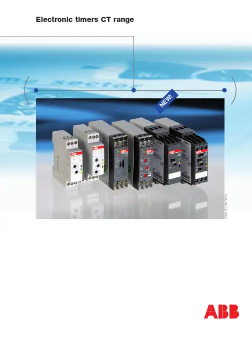
2C D C 255 056 F 0006Electronic timers CT rangeNE W!21S V C 110 000 F 05071S V C 110 000 F 0506Connecting screws in M3 (Pozidrive 1)Easy actuation of thec onnecting combination screws, with pozidrive, pan- or cross-head screwdriver.Remote p otentiometerconnectionThe CT -S range offers thep ossibility of connecting a r emote potentiometer for the fi ne adjustment of the time delay. When an externalp otentiometer is connected, the internal, frontface potentiometer is disabled.or many years, ABB’s CT range of electronic timers has been used in applications world-wide and has proven its excellent functionality in daily use, even under harshest environmentalc onditions. T hree ranges of electronic timers provide timing functions for all applications: T he highly sophisticated CT-S range is ideallys uitable for universal use. The CT-D range with modular design in only 17.5 mm wide enclosures.And the CT-E range offers an excellent price/performance ratio and is an ideal s olution for serial applications. Make use of ABB’s e xcellent competence in i ndustry e lectronics.FElectronic timers CT rangeCT-D rangeNE W : 2c /o c o n t a c t s32C D C 255 056 F 00062C D C 253 065 F 00062C D C 253 010 F 00032C D C 253 011 F 00032C D C 253 064 F 00062C D C 253 062 F 00062C D C 253 132 F 0006Direct reading scalesDirect setting of the time delay without any additionalc alculation provides accurate time delay adjustment.SafetyThe “real distance” is hidden.Our products‘ air and creepage distances exceed international standards, and substantiallyi ncrease the safety of these products.LEDs for status indicationAll actual operational states are displayed by frontface LEDs, thus simplifying commissioning and troubleshooting.Sealable transparentc over Protection against u nauthorized changes of time and t hreshold values. Available as ana ccessory.Integrated marker labelsIntegrated markers allow the product to be marked quickly and simply. No additional marking labels are required (CT -S range).Time range preselection and fi ne adjustmentDirect assignment of the pre-selected time range to the fi ne adjustment potentiometer scale by multicolor scales.42C D C 256 059 F 00062C D C 253 022 F 0004multifunctionalOperating controls➀ LEDs for status indication U - green LED:c ontrol supply voltage applied timingR - yellow LED:output relay energized ➁ Time range adjustment➂ Fine adjustment of the time delay ➃ Preselection of the timing functionElectronic timers CT -D range: The modular timerssingle-functional➂➁ ➀➂➁ ➃NE W : 2c /o c o n t a c t s52C D C 255 058 F 00062C D C 252 047 F 00062C D C 252 048 F 00062C D C 253 066 F 00062C D C 253 132 F 00062C D C 253 033 F 00042C D C 253 021 F 000417.5 mm*partly pendingModular – CT -D rangeDirect reading scalesDirect setting of the time delay without anyadditional calculation provides accurate time delay adjustment.LEDs for status indicationAll actual operational states are displayed byfrontface LEDs, thus simplifying commission-ing and fault troubleshooting.Connecting terminalsWide terminal spacing allows connection of wires:– 2 x 1.5 mm² (2 x 16 AWG) with wire end ferrules or– 2 x 2.5 mm² (2 x 14 AWG) without ferrules.Width 17.5 mmWith their width of 17.5 mm, the CT -D range t imers are ideally suited for i nstallation in distribution p anels.Switching currentsThe CT -D range timers allow an output load of up to 6 A on devices with 1 c/o contact and up to 5 A on devices with 2 c/o contacts.Control input: Voltage-r elated triggering,non-polarized, capable ofs witching a parallel load.1S V C 110 000 F 05031S V C 110 000 F 0500➀➁ ➂➃6multifunctional Operating controls➀ LEDs for status indication U – green LED:control supply voltage applied R – red LED:output relay energized ➁ Time range adjustment➂ Fine adjustment of the time delay ➃ Preselection of the timing functionElectronic timers CT -E range: The economic timerssingle-functional2C D C 255 011 F 00051S V C 110 000 F 05081S V C 110 000 F 050672C D C 255 011 F 0005Economy – CT -E rangeConnecting screws in M3(Pozidrive 1)Easy and fast tightening and release of the connecting screws with pozidrive, pan- or crosshead screwdriver.Direct reading scalesDirect setting of the time delay without any additional calculation provides accurate time delay adjustment.LEDs for status indicationAll actual operational states are displayed by frontface LEDs, thus simplifyingc ommissioning and troubleshooting.82C D C 256 060 F 00062C D C 256 061 F 0006➄➁ ➂ ➀➃Electronic timers CT -S range: The high-end timersmultifunctional Operating controls➀ LEDs for status indication U/T – green LED:control supply voltage applied timingR/R1/R2 – yellow LED:1. /2. output relay energized ➁ Time range adjustment➂Fine adjustment of the time delay➃ Preselection of the timing function ➄ Set the 2nd c/o contact as an instantaneous contactsingle-functional92C D C 255 057 F 00061S V C 110 000 F 05072C D C 253 010 F 00032C D C 253 063 F 00062C D C 253 062 F 0006 High end – CT -S rangeIndication of operational statesAll actual operational states are displayed by front-face LEDs, thus simplifyingc ommissioning and troubleshooting.Double-chamber cage connectingt erminals Double-chamber cage connecting terminals provide connection of wires up to 2 x 2.5 mm 2(2 x 14 AWG), rigid or fi ne-strand, with orwithout wire end ferrules. Potential distribution does not require additional terminals.Connection of remote p otentiometersAn external potentiometer can be connected to the CT -S devices to make fi ne adjustments to the time ranges. The internal potentiometer switches off automatically when an external one is connected.Control input with volt-free 3) or voltage-related 4)t riggering 1)The new CT -S range offers two types of devices:one with volt-free and one with voltage-related triggering.The control inputs of the devices with voltage-related triggering are capable of switching parallel load and are not polarized. They can be powered either by the control supply voltage applied to A1 or by another voltage out of the rated control supply voltage range.NE W!1) selected devices 2) pending3) volt-free = dry/fl oating4) voltage-related = wet/non-fl oatingSelection guides and order references for electronic timers pe* with gold contactsControl input with voltage-related (wet/non-fl oating) triggeringControl input with volt-free (dry/fl oating) triggering Accessories: Sealable cover in 22,5 mm width: 1SVR 430 005 R 0100 Product Diameter Protection Resistance Ordercode Remote potentiometer 30.5 mm IP65 50 kΩ1SVR 700 800 R1000 Remote potentiometer 22.5 mm IP65 50 kΩ1SVR 701 800 R1000 Remote potentiometer 10.5 mm IP65 50 kΩ1SVR 214 017 R0900 EW!10CT-E range1) Functions: ON-delay, OFF-delay, impulse-ON, fl asher starting with ON or OFF, pulse shaper Control input with voltage-related (wet/non-fl oating) triggering2) Non-polarized, not capable of switching a parallel load11/12CT -D range, CT -E range, CT -S rangeCT -E range, solid state output1) contactless, function and time range selection via external jumpers 2) Functions: ON-delay (AC/DC), Impulse-ON (AC only), Flasher starting with ON (AC only), Flasher starting with OFF (AC only)1) 20...100 ms in 10 ms increments13Conversion table CT-S range 1SVR 430 ... -> 1SVR 630 ... CT-S rangeType old Order code old Type new /alternative Order code new / a lternativeMultifunctional timersCT-MFS1SVR 430 010 R0200CT-MVS.21CT-MFS.211SVR 630 010 R0200 1SVR 630 010 R0200CT-MVS1SVR 430 023 R0200CT-MVS.221SVR 630 020 R3300CT-MBS1SVR 430 010 R1200CT-MVS.22CT-MBS.221SVR 630 020 R3300 1SVR 630 010 R3200CT-MBS1SVR 430 012 R0200CT-MVS.22CT-MBS.221SVR 630 020 R3300 1SVR 630 010 R3200CT-MBS1SVR 430 011 R2200CT-MVS.231SVR 630 021 R2300CT-MBS1SVR 430 010 R1100CT-MVS.12CT-MBS.221SVR 630 020 R3100 1SVR 630 010 R3200CT-MBS1SVR 430 013 R0100CT-MVS.12CT-MBS.221SVR 630 020 R3100 1SVR 630 010 R3200CT-MBS1SVR 430 011 R2100CT-MVS.231SVR 630 021 R2300ON-delay timersCT-ERS1SVR 430 100 R1100CT-ERS.211SVR 630 100 R0300 CT-ERS1SVR 430 102 R0100CT-ERS.121SVR 630 100 R3100 CT-ERS1SVR 430 101 R2100CT-MVS.231SVR 630 021 R2300CT-ERS1SVR 430 103 R0100CT-MVS.21CT-MFS.211SVR 630 010 R0200 1SVR 630 010 R0200CT-ERS1SVR 430 100 R1200CT-ERS.211SVR 630 100 R0300 CT-ERS1SVR 430 103 R0200CT-ERS.221SVR 630 100 R3300 CT-ERS1SVR 430 101 R2200CT-MVS.231SVR 630 021 R2300ROFF-delay timersCT-AHS1SVR 430 113 R0100CT-APS.12CT-AHS.221SVR 630 180 R3100 1SVR 630 110 R3300CT-AHS1SVR 430 113 R0200CT-APS.22CT-AHS.221SVR 630 180 R3300 1SVR 630 110 R3300CT-APS1SVR 430 183 R0300CT-APS.221SVR 630 180 R3300 CT-ARS1SVR 430 120 R0100CT-ARS.221SVR 630 120 R3300 CT-ARS1SVR 430 120 R0300CT-ARS.121SVR 630 120 R3100 CT-VBS1SVR 430 261 R6000CT-VBS.171SVR 430 261 R6000 CT-VBS1SVR 430 261 R5000CT-VBS.181SVR 430 261 R5000ON- and OFF-delay timersCT-EAS1SVR 430 173 R0100CT-MXS.221SVR 630 030 R3300 CT-EAS1SVR 430 173 R0200CT-MXS.221SVR 630 030 R3300 CT-EVS1SVR 430 193 R0100CT-MXS.221SVR 630 030 R3300Type old Order code old Type new /alternativeOrder code new /a lternative Impulse-ON relaysCT-VWS1SVR 430 132 R0100CT-WBS.221SVR 630 040 R3300 CT-VWS1SVR 430 133 R0200CT-WBS.221SVR 630 040 R3300 Impulse-OFF relaysCT-AWS1SVR 430 143 R0100CT-MVS.121SVR 630 020 R3100 CT-AWS1SVR 430 143 R0200CT-MVS.121SVR 630 020 R3100 FlasherCT-EBS1SVR 430 152 R0100CT-WBS.221SVR 630 040 R3300 CT-EBS1SVR 430 153 R0200CT-WBS.221SVR 630 040 R3300 Pulse generatorsCT-TGS1SVR 430 163 R0100CT-MXS.221SVR 630 030 R3300 CT-PGS1SVR 430 253 R0100CT-MXS.221SVR 630 030 R3300 Star-delta change-over timerCT-YDAV1SVR 430 203 R0200CT-SDS.221SVR 630 210 R3300 CT-YDAV1SVR 430 201 R2300CT-SDS.231SVR 630 211 R2300 CT-YDEW1SVR 430 213 R0200CT-SDS.221SVR 630 210 R3300 Switching relaysCT-IRS1SVR 430 220 R9100CT-IRS.161SVR 430 220 R9100 CT-IRS1SVR 430 220 R8100not replaced-CT-IRS1SVR 430 221 R7100CT-IRS.141SVR 430 221 R7100 CT-IRS1SVR 430 220 R9300CT-IRS.261SVR 430 220 R9300 CT-IRS1SVR 430 220 R8300not replaced-CT-IRS1SVR 430 221 R7300CT-IRS.241SVR 430 221 R7300 CT-IRS1SVR 430 230 R9300CT-IRS.261SVR 430 220 R9300 CT-IRS1SVR 430 231 R7300CT-IRS.241SVR 430 231 R7300 CT-IRS1SVR 430 220 R9400CT-IRS.361SVR 430 220 R9400 CT-IRS1SVR 430 220 R8400not replaced-CT-IRS1SVR 430 221 R1400CT-IRS.351SVR 430 221 R1400D r u c k s c h r i f t -N r . 2C D C 110 003 B 0203 (04/06) P r i n t e d i n t h e F e d e r a l R e p u b l i c o f G e r m a n yABB STOTZ-KONTAKT GmbHPostfach 10 16 80, 69006 Heidelberg Eppelheimer Straße 82, 69123 Heidelberg GERMANY/lowvoltage –> Control Products –> Electronic Relays。
anytime棋钟说明书摘要:1.引言2.产品简介3.安装与设置4.使用方法5.注意事项6.结论正文:【引言】Anytime 棋钟是一款专业的围棋、象棋、国际象棋等多功能计时器,适用于比赛、训练和日常娱乐。
本文将为您详细介绍如何使用Anytime 棋钟,帮助您更好地享受棋类游戏的乐趣。
【产品简介】Anytime 棋钟采用高清晰度的LCD 显示屏,具有良好的触控反应速度,可实现多种棋类游戏的计时功能。
它具备如下特点:1.多功能:支持围棋、象棋、国际象棋等多种棋类游戏的计时。
2.高精度:采用高精度传感器,计时准确无误。
3.便携性:体积适中,方便携带,适用于各种场合。
【安装与设置】1.开箱:首先,取出Anytime 棋钟,检查配件是否齐全。
2.安装电池:根据电池仓指示,安装适量电池。
3.设置:按下开关键,显示屏亮起。
通过触摸屏设置棋钟的工作模式、时间设置等参数。
【使用方法】1.选择模式:根据需要,选择围棋、象棋、国际象棋等模式。
2.设置时间:根据比赛或训练要求,设置合适的用时。
3.开始计时:将棋钟放置在棋盘旁边,开始游戏。
棋钟将自动为您计时。
4.暂停与恢复:游戏过程中如需暂停,可按下暂停键;恢复游戏时,按下启动键。
【注意事项】1.请勿将棋钟浸入水中或置于潮湿环境中,以免损坏。
2.使用时,请确保棋钟放置在平稳的地面上,以免发生意外损坏。
3.如遇问题,请勿自行拆解修理,以免造成安全事故。
如需维修,请联系售后服务。
【结论】Anytime 棋钟是一款集多功能、高精度、便携性于一体的优质棋类游戏计时器。
通过本指南,相信您已经掌握了如何使用Anytime 棋钟的方法。

为了加强学习管理,本次系统改造增加了防挂机学习计时功能。
现对学习计时的相关事项说明如下:
1、开始学习时,系统会判断已学习时间是否已满足要求,如果不满足要求,则启动学习计时器;否则计时器不启动。
时间已满,计时器不启动
时间不满,计时器启动
2、当点击按钮退出学习时,计时器将停止计时。
3、学习计时器每分钟会向服务器发送报告,当发现已学习的时间满足要求后,计时器自动停止。
4、当采用关闭浏览器等各种方式停止学习时,计时器后台将停止计时。
5、为防止挂机,学习计时器会在启动15分钟后弹出验证窗体,需填写验证码进行验证(目前采用2位数的加减法运算结果作为验证码),若超过时间(10分钟)未正确填写提交验证码,计时将停止。
正确填写提交验证码15分钟后,将进行下一次验证。
6、为防止多开挂机,计时器系统只允许一个用户同时进行一个学习,若多开学习,原来的学习将报"学习报告失败,指定的课程id不匹配!"的错误提示并停止计时。
XMT-50a十段计时器显示仪!提请注意:1。
仪表在通电使用中,不允许将机芯移出机壳,不能随意触摸或接近后面板,以免触电危险。
2.仪表的安装及调试应由技术人员来完成。
第一部分产品介绍§1、产品概述XMT—A型系列智能化仪表是以先进的单片机及微电子技术为中心,应用霍尔传感器或旋转编码器,由北京智能拓维技术研究所设计制作而成的新一代计数、计时、计米、频率、速度等仪表,广泛应用于现代工程系统中。
其应用领域现以渗透到国防技术、航空、航天、铁路、冶金、化工、电力、农业等国民经济各部门以及日常生活中。
该系列仪表功能强,使用方便灵活,性能稳定可靠,精度高,主要特点如下:1.一机多用,功能齐全,任意选择,方便用户使用;2.①计数器/计米器可外接旋转编码器和霍尔传感器使用②,每种方式又可分为带倍率和不带倍率两种;3、①计时器集正计时.倒计时于一体,正.反计时共10种延时范围.②每一种延时范围内有10个时间段可任意选择;4、频率和转速表具有两大功能,其中频率计数又分为,1~9999HZ和0.1~999.9HZ两个档,输出控制配有6种继电器工作方式。
5.六种继电器方式可任意选择;6.对输入输出信号实行光电隔离,软硬件加看门狗功能,使仪表抗干扰能力强.7.仪表采用智能化的工作模式,用户可根据实际需要,通过面板上的触摸键,灵活地改变仪表的工作方式和参数设置。
§2、综合技术参数1、仪表工作环境:温度50℃以下;湿度90%以下;2、仪表精度:0。
2---0。
5级3、标准模拟信号输出:①电流输出:4--20mA②电压输出:0—5V4、整机功耗:3VA5、供电电源:①、仪表内部不含交流开关电源:直接输入AC220V50HZ。
②、仪表内部含交流开关电源:交流输入可在85V—265V50HZ之间。
6、采用国际通用面板面板上采用触摸按键。
通过按键所设定的值掉电时不丢失。
7、外型尺寸/开孔尺寸48×48/44×4448×96/44×9296×48/92×4496×96/91×91160×80/15 8仪表端子接线图48×48/44×4448×96/44×9296×48/92×4448×48/44×44§3、仪表安装与注意事项:1、仪表的安装:仪表的安装形式是嵌入式,应安装在厚度为1—3。
Electronic timer CT-APS.12OFF-delayed with 1 c/o (SPDT) contactThe CT-APS.12 is an electronic timer from the CT-S range with OFF-delay and 10 time ranges.All electronic timers from the CT-S range areavailable with two different terminal versions. You can choose between the proven screw connection technology (double-chamber cage connection terminals) and the completely tool-free Easy Connect Technology (push-in terminals).Characteristics–Rated control supply voltage 24-48 V DC, 24-240 V AC –OFF-delay timer with auxiliary voltage –10 time ranges (0.05 s - 300 h)–Control input with voltage-related triggering to start timing –Precise adjustment by front-face operating elements –Screw connection technology orEasy Connect Technology available–Housing material for highest fire protection classificationUL 94 V-0–Tool-free mounting and demounting on DIN-rail – 1 c/o (SPDT) contact –Width of 22.5 mm– 2 LEDs for status indication Order Data Electronic TimersType Rated control supply voltage Connection technology Time ranges Order codeCT-APS.12P 24-48 V DC, 24-240 V AC Push-in terminals 0.05 s - 300 h 1SVR 740 180 R3100CT-APS.12S24-48 V DC, 24-240 V ACScrew type terminals0.05 s - 300 h1SVR 730 180 R3100AccessoriesType DescriptionOrder codeADP .01Adapter for screw mounting 1SVR 430 029 R0100MAR.01Marker label1SVR 366 017 R0100COV.11Sealable transparent cover1SVR 730 005 R0100Approvals A UL 508, CAN/CSA C22.2 No.14C GL D GOST K CB scheme ECCCKennzeichnungen aCE bC-Tick2C D C 251 037 V 00112 - Electronic timer CT-APS.12 | Data sheetConnection technologyMaintenance free Easy Connect Technology with push-in terminalsType designation CT-xxS.yyPApproved screw connection technology with double-chamber cage connection terminals Type designation CT-xxS.yySPush-in terminals–Tool-free connection of rigid and flexible wires withwire end ferrule according to DIN 46228-1-A 4-9, DIN 46228-4-E 4-10Wire size: 2 x 0.5-1.5 mm², (2 x 20 - 16 AWG) –Easy connection of flexible wires without wire endferrule by opening the terminals –No retightening necessary–One operation lever for opening both connectionterminals–For triggering the lever and disconnecting of wiresyou can use the same tool (Screwdriver according to DIN ISO 2380-1 Form A 0.8 x 4 mm (0.0315 x 0.157 in), DIN ISO 8764-1 PZ1 ø 4.5 mm (0.177 in))–Constant spring force on terminal point independentof the applied wire type, wire size or ambientconditions (e. g. vibrations or temperature changes) –Opening for testing the electrical contacting –Gas-tightDouble-chamber cage connection terminals–Terminal spaces for different wire sizes:fine-strand with/without wire end ferrule: 1 x 0.5-2.5 mm² (2 x 20 - 14 AWG), 2 x 0.5-1.5 mm² (2 x 20 - 16 AWG) rigid:1 x 0.5-4 mm² (1 x 20 - 12 AWG), 2 x 0.5-2.5 mm² (2 x 20 - 14 AWG)–One screw for opening and closing of both cages –Pozidrive screws for pan- or crosshead screwdriversaccording to DIN ISO 2380-1 Form A 0.8 x 4 mm (0.0315 x 0.157 in), DIN ISO 8764-1 PZ1 ø 4.5 mm (0.177 in)Both the Easy Connect Technology with push-in terminals and screw connection technology with double-chamber cageconnection terminals have the same connection geometry as well as terminal position.2C D C 253 025 F 00112C D C 253 026 F 0011Data sheet | Electronic timer CT-APS.12 - 3Functions Operating controlsRotary switch for the preselection of the time range Fine adjustment of the time delay3 Indication of operational statesU: green LED - control supply voltage / timing R: yellow LED - status of output relay4 Marker labelApplicationThe CT-S range timers are designed for use in industrial applications. They operate over an universal range of supplyvoltages and a large time delay range, within compact dimensions. The easy-to-set front-face potentiometers, with direct reading scales, provide accurate time delay adjustment.Operating modeThe CT-APS.12 with 1 c/o contact offers 10 time ranges, from 0.05 s to 300 h, for the adjustment of the time delay. The time delay range is rotary switch selectable. The fine adjustment of the time delay is made via an internal potentiometer, with a direct reading scale, on the front of the unit.Timing is displayed by a flashing green LED labelled U/T.2C D C 251 037 V 0011Function diagramOFF-delay with auxiliary voltageThis function requires continuous control supply voltage for timing.If control input A1-Y1/B1 is closed, the output relay energizes immediately. If control input A1-Y1/B1 is opened, the time delay starts. The green LED flashes during timing. When the selected time delay is complete, the output relay de-energizes and the flashing green LED turns steady.If control input A1-Y1/B1 recloses before the time delay is complete, the time delay is reset and the output relay does not change state. Timing starts again when control input A1-Y1/B1 re-opens.If control supply voltage is interrupted, the output relay de-energizes and the time delay is reset.Electrical connectionWiring instructionsControl input (voltage-related triggering)The control input Y1/B1 is triggered with electric potential against A2. It is possible to use the control supply voltage from terminal A1 or any other voltage within the rated control supply voltage range.4 - Electronic timer CT-APS.12 | Data sheetTechnical DataData at T a = 25 °C and rated values, unless otherwise indicatedInput circuitsSupply circuit A1‑A2Rated control supply voltage U S24-48 V DC, 24-240 V ACRated control supply voltage U S tolerance24-48 V DC-15...+10 %24-240 V AC-15...+10 %Rated frequency DC n/aAC50/60 HzFrequency range AC47-63 HzTypical current / power consumption24 V DC230 V AC115 V AC24-48 V DC12 mA /on request- / -- / -24-240 V AC- / -50 mA /on request33 mA / on requestPower failure buffering time24 V DC min. 15 ms230 V AC min. 20 msControl circuitControl input, control function A1-Y1/B1start timing externalKind of triggering voltage-related triggeringRestistance to reverse polarity yesPolarized noCapable for switching a parallel load yesMaximum cable length to the control inputs50 m - 100 pF/mMinimum control pulse length20 msControl voltage potential see rated control supply voltage U SCurrent consumption of the control input24 V DC 1.2 mA230 V AC8 mATiming circuitKind of timer Single-function timer OFF-delay with auxiliary voltageTime ranges 0.05 s - 300 h0.05-1 s, 0.15-3 s, 0.5-10 s, 1.5-30 s, 5-100 s,15-300 s, 1.5-30 min, 15-300 min, 1.5-30 h, 15-300 h Recovery time< 80 msRepeat accuracy (constant parameters)Δt <± 0.2 %Accuracy within the rated control supply voltage toleranceΔt < 0.004 %/VAccuracy within the temperature rangeΔt < 0.03 %/°CUser interfaceIndication of operational statesControl supply voltage / timing U/T: green LED V: control supply voltage appliedU/T: green LED W: timingRelay status R: yellow LED V: output relay energizedData sheet| Electronic timer CT-APS.12 - 5Output circuitsKind of output15-16/18Relay, 1 c/o (SPDT) contact Contact material Cd-freeRated operational voltage U e250 VMinimum switching voltage / Minimum switching current12 V / 10 mAMaximum switching voltage / Minimum switching current see ‘Load limit curves’ on page 8 Rated operational current I e (IEC/EN 60947-5-1)AC12 (resistive) at 230 V 4 AAC15 (inductive) at 230 V 3 ADC12 (resistive) at 24 V 4 ADC13 (inductive) at 24 V 2 AAC rating (UL 508)utilization category (ControlCircuit Rating Code)B 300max. rated operational voltage300 V ACmax. continuous thermalcurrent at B 3005 Amax. making / breakingapparent power at B 3003600/360 VAMechanical lifetime30 x 106 switching cycles Electrical lifetime AC12, 230 V, 4 A0.1 x 106 switching cyclesMaximum fuse rating to achieve short-circuit protection (IEC/EN 60947-5-1)n/c contact 6 A fast-acting n/o contact10 A fast-actingGeneral dataElectrical connection6 - Electronic timer CT-APS.12 | Data sheetEnvironmental dataAmbient temperature ranges operation-25...+60 °Cstorage-40...+85 °CDamp heat, cyclic (IEC/EN 60068-2-30) 6 x 24 h cycle, 55 °C, 95 % RH Vibration, sinusoidal (IEC/EN 60068-2-6)functioning40 m/s2, 10-58/60-150 Hzresistance60 m/s2, 10-58/60-150 Hz, 20 cycles Vibration, seismic (IEC/EN 60068-3-3)functioning20 m/s²Shock, half-sine (IEC/EN 60068-2-27)functioning100 m/s2, 11 ms, 3 shocks/directionresistance300 m/s2, 11 ms, 3 shocks/direction Isolation dataRated insulation voltage U i input circuit / output circuit500 VRated impulse withstand voltage U imp between allisolated circuits (IEC/EN 60664-1, VDE 0110)4 kV; 1.2/50 µsPower-frequency withstand voltage test between all isolated circuits (test voltage)routine test: 2.0 kV; 50 Hz, 1 s type test: 2.5 kV; 50 Hz, 1 minBasic insulation (IEC/EN 61140)input circuit / output circuit500 VProtective separation (IEC/EN 61140; IEC/EN 50178;VDE 0106 part 101 and part 101/A1)input circuit / output circuit250 VPollution degree(IEC/EN 60664-1, VDE 0110)3Overvoltage category(IEC/EN 60664-1, VDE 0110)IIIStandards / DirectivesProduct standard IEC 61812-1, EN 61812-1 + A11,DIN VDE 0435 part 2021Low Voltage Directive2006/95/ECEMC Directive2004/108/ECRoHS Directive2002/95/ECElectromagnetic compatibilityInterference immunity to IEC/EN 61000-6-1, IEC/EN 61000-6-2electrostatic discharge IEC/EN 61000-4-2Level 3, 6 kV / 8 kVradiated, radio-frequency, electromagnetic field IEC/EN 61000-4-3Level 3, 10 V/m (1 GHz) / 3 V/m (2 GHz) /1 V/m (2.7 GHz)electrical fast transient / burst IEC/EN 61000-4-4Level 3, 2 kV / 5 kHzsurge IEC/EN 61000-4-5Level 4, 2 kV A1-A2conducted disturbances, induced by radio-frequency fieldsIEC/EN 61000-4-6Level 3, 10 Vharmonics and interharmonics IEC/EN 61000-4-13Level 3Interference emission IEC/EN 61000-6-3, IEC/EN 61000-6-4high-frequency radiated IEC/CISPR 22, EN 55022Class Bhigh-frequency conducted IEC/CISPR 22, EN 55022Class BData sheet| Electronic timer CT-APS.12 - 7Technical diagramsLoad limit curves8 - Electronic timer CT-APS.12 | Data sheetDimensionsin mm and inchesAccessoriesin mm and inchesFurther documentationDocument title Document type Document numberElectronic Products and Relays Technical catalogue2CDC 110 004 C020xCT-APS, CT-ERS, CT-MVS, CT-SDS Instruction manual1SVC 730 020 M0000You can find the documentation on the internet at /lowvoltage -> Control Products ->Electronic Relays and Controls -> Time RelaysData sheet| Electronic timer CT-APS.12 - 9ABB STOTZ‑KONTAKT GmbHP. O. Box 10 16 8069006 Heidelberg, Germany Phone: +49 (0) 6221 7 01-0Fax: +49 (0) 6221 7 01-13 25E-mail:*****************.comYou can find the address of your local sales organization on theABB home page/contacts-> Low Voltage Products and Systems Contact usNote:We reserve the right to make technical changes or modify the contents of this document without prior notice. With regard to purchase orders, the agreed particulars shall prevail. ABB AG does not accept any responsibility whatsoever for potential errors or possible lack of information in this document.We reserve all rights in this document and in the subject matter and illustrations contained therein. Any reproduction, disclosure to third parties or utilization of its contents – in wholeor in parts – is forbidden without prior written consent of ABB AG.Copyright© 2011 ABBAll rights reserved D o c u m e n t n u m b e r 2 C D C 1 1 1 1 1 5 D 0 2 0 1 p r i n t e d i n G e r m a n y ( 0 4 / 2 0 1 1 )。
"ton" 通常是指"Timer On Delay",在工业自动化和控制系统中是一个常见的计时器类型。
在PLC(可编程逻辑控制器)或类似的控制系统中,TON 计时器用于在输入信号激活后,延迟一段时间后产生输出信号。
以下是一个简单的例子,说明了TON 计时器的基本用法。
请注意,具体的语法和功能可能会根据使用的编程语言或控制系统而有所不同。
### 例子(使用ladder diagram 表示):```ladder|--[ ]----( )----[ ]--( )--| Start TON Output```在这个例子中:- `[ ]` 表示一个输入或输出线圈。
- `( )` 表示一个逻辑元件,这里是TON 计时器。
- `Start` 是一个输入信号,表示启动计时器。
- `Output` 是计时器的输出信号。
在PLC 编程中,你需要设置TON 计时器的参数,如时间延迟。
以下是一个潜在的伪代码示例:```pseudoTON Timer1;BOOL StartButton;BOOL Output;// 在主循环中StartButton = ReadStartButton(); // 读取启动按钮状态// 当启动按钮按下时,启动计时器IF StartButton THENTimer1.Start();END_IF;// 检查计时器是否已经完成IF Timer1.Done() THENOutput = TRUE; // 计时器已完成,设置输出信号ELSEOutput = FALSE; // 计时器尚未完成,保持输出信号为FALSEEND_IF;// 在PLC 中,Output 可能用于控制某个操作,例如启动电机或者其他设备```这只是一个简单的例子,实际上,PLC 编程可能涉及更复杂的逻辑和多个计时器的协同工作。
具体的语法和操作方式取决于使用的PLC 型号和相应的编程语言。
计时器的应用
今天我们学习一个新的模块“计时器”,一听这个模块就能猜到,他的使用跟时间有关系,那么问题来了:时间是什么?
时间是一个较为抽象的概念,包含了时刻和时段两个概念。
时间是人类用以描述物质运动过程或事件发生过程的一个参数,确定时间,是靠不受外界影响的物质周期变化的规律。
所以时间流逝,永不停止;时间惟一,无可逆转更改。
同样在程序执行过程中也有时间流逝,我们将程序运行过程中的机器时间赋值到时间变量来,以此来将时间装换成我们可以看得懂的时间。
今天我们需要了解的就是关于“计时器”模块的使用,当然“计时器”模块的使用一般会配合“时钟复位”模块一起使用。
“计时器”模块是用来记录程序从开始执行到当前位置的时间,“时钟复位”模块则是将程序从开始执行到该模块位置的时间清零。
这样就保证了“计时器”
模块开始执行的时间是从零开始的,避免之前保存的时间对程序的运行造成影响。
一般来说,我们把“计时器”模块开始计时的时间称为时间点,把程序执行完成所需要的时间称为时间段,一般我们会通过判断时间段的数值大小,决定执行不同的程序。
比如我们在主控上连接一个RGB彩灯(接口为2),然后我们通过时间控制灯亮不同颜色,需要实现的效果:当计时器记录时间小于1秒时,亮黄灯;当大于1秒且小于3秒时,亮绿灯;当大于3秒且小于6秒时亮红灯;当大于6秒时,时钟复位,重复运行。
流程图示例
Scratch示例
这是我们针对“计时器”模块的一个简单应用,切记一点:一般情况下,计时器模块一定是配合时钟复位一起使用的。