Flow patterns past two circular cylinders in proximity
- 格式:pdf
- 大小:4.53 MB
- 文档页数:11


帕金森转棒实验的英文The Parkinson's Turning Stick ExperimentParkinson's disease is a neurodegenerative disorder that affects the central nervous system. It primarily affects movement, causing tremors, stiffness, and difficulty with balance and coordination. One of the challenges faced by individuals with Parkinson's disease is turning while walking. This experiment aims to investigate the effectiveness of a specialized turning stick in improving turning abilities for Parkinson's patients.The experiment will involve a group of participants diagnosed with Parkinson's disease. They will be divided into two groups: an experimental group and a control group. The experimental group will use the turning stick, while the control group will not. The participants will undergo a series of assessments and measurements before and after the intervention.The turning stick is designed to provide support and stability during turning movements. It has a unique handle that allows for a secure grip and a rotating mechanism thatassists in turning. The stick will be adjusted to each participant's height and handedness for optimal comfort and ease of use.The assessments will include various tests to evaluate the participants' turning abilities, such as the Timed Up and Go test, which measures the time taken to stand up from a chair, walk a short distance, turn around, and sit back down. Other tests may include the Functional Gait Assessment and the Freezing of Gait questionnaire, which assesses freezing episodes during walking.The participants in the experimental group will receive training on how to use the turning stick effectively. They will practice walking and turning with the stick under the supervision of a physiotherapist. The control group will not receive any specific intervention or training related to turning.After a designated period, the participants will undergo the same assessments and measurements as before the intervention. The data collected will be analyzed to determine if there are any significant differences betweenthe experimental and control groups in terms of turning abilities.It is hypothesized that the participants in the experimental group, who use the turning stick, will show improvements in turning abilities compared to the control group. The specialized handle and rotating mechanism of the turning stick are expected to provide additional support and stability during turning movements, thereby reducing the risk of falls and improving overall mobility.If the results of the experiment support the hypothesis, it could lead to the development of more effective interventions and assistive devices for individuals with Parkinson's disease. The turning stick could potentially be incorporated into rehabilitation programs and daily routines to enhance mobility and quality of life for Parkinson's patients.帕金森转棒实验帕金森病是一种神经退行性疾病,影响中枢神经系统。
各论I题库第一篇运动系统 (2)第一章骨与骨的连接 (2)第二章骨骼肌解剖结构 (29)第三章骨骼肌生理 (45)第二篇血液与造血系统 (58)第一章血液的形态学与血细胞的发生 (58)第二章血液生理62 第三章淋巴和造血系统疾病 (77)第三篇循环系统 (88)第一章循环系统解剖 (88)第二章循环系统的组织结构与发生93 第三章血液循环生理 (108)第四章循环系统病理153 第五章循环系统功能障碍156 第六章心血管系统药理 (178)鸣谢:初菁菁、郑佳佳、董军乐、胡慧美、王靖、王懿、范欣、秦祯蔚、彭德清、王灿锋、姜治伟等人的辛苦整理~医学院0707&07032009.3.10第一篇运动系统第一章骨与骨的连接第一节骨学总论一、骨的分类1. 下列哪项不是青枝骨折的特征A. 多发生在儿童B. 是一种不完全骨折C. 无明显功能障碍D. 无局部压痛及纵形叩击痛E. 畸形不严重2. 骨损伤后能参与修复的结构是A.骨质B.骨骺C.骨膜D.骨髓E.关节面的软骨3. 黄骨髓存在于A. 所有骨的内部B.幼儿长骨骨干内部C.成人长骨骨干内部D. 幼儿长骨骨骺内部E. 成人扁骨内部4. 有关骨髓腔正确的是A. 位于骨骺内B. 位于长骨的骨干内C. 成人骨髓腔内含红骨髓D. 小儿骨髓腔内含黄骨髓E. 以上全不对5. 有关红骨髓正确的是A. 成人存在于髓腔内B. 不存在于板障内C. 胎儿期造血,成年期不造血D. 髂骨、胸骨、椎骨内终生保存红骨髓E. 以上全不对6. 有关骨的构造,正确的说法是A. 骨干由松质构成B. 骨骺由密质构成C. 骨膜有血管无神经D. 骨髓有神经无血管E. 以上全不对答案:DCCBDE二、骨的构造(共6题)1. 下列哪项不是青枝骨折的特征A. 多发生在儿童B. 是一种不完全骨折C. 无明显功能障碍D. 无局部压痛及纵形叩击痛E. 畸形不严重2. 骨损伤后能参与修复的结构是A.骨质B.骨骺C.骨膜D.骨髓E.关节面的软骨3. 黄骨髓存在于A. 所有骨的内部B.幼儿长骨骨干内部C.成人长骨骨干内部D. 幼儿长骨骨骺内部E. 成人扁骨内部4. 有关骨髓腔正确的是A. 位于骨骺内B. 位于长骨的骨干内C. 成人骨髓腔内含红骨髓D. 小儿骨髓腔内含黄骨髓E. 以上全不对5. 有关红骨髓正确的是A. 成人存在于髓腔内B. 不存在于板障内C. 胎儿期造血,成年期不造血D. 髂骨、胸骨、椎骨内终生保存红骨髓E. 以上全不对6. 有关骨的构造,正确的说法是A. 骨干由松质构成B. 骨骺由密质构成C. 骨膜有血管无神经D. 骨髓有神经无血管E. 以上全不对答案:DCCBDE三、骨的化学成分和物理性质及年龄差异无第二节中枢骨一、躯干骨1. 男性,35岁,头痛、恶心、呕吐、发热,诊断为脑脊髓膜炎,要行腰椎穿刺抽取脑脊液化验,其进针部位应在A.第12胸椎与第1腰椎棘突间隙B.第1腰椎与第2腰椎棘突间隙C.第3腰椎与第4腰椎棘突间隙D.第5腰椎与骶椎间隙E.第2对骶后孔处2. 关于椎弓的说法,错误的是A.位于椎体的后方B.呈半环状C.与椎体共同围成椎孔D.由一对椎弓板构成E.相邻椎弓间有黄韧带3. 关于椎体的说法,错误的是A.呈短圆柱状B.位于椎骨前部C.主要由松质构成D.表面有一层密质E.椎体中央有椎孔4. 躯干骨在体表易摸到的骨性标志是A.全部颈椎棘突B.全部肋骨C.胸椎横突D.胸骨角E.骶岬5. 骶骨的正确描述是A.有5对骶前孔B.由4块骶椎融合而成C.与第4腰椎相关节D.骶管内有脊髓通过E.于骶角处可寻骶管裂孔进行神经阻滞麻醉6. 骶管麻醉的穿刺部位正对A.骶角B.骶管裂孔C.骶前孔D.骶后孔E.骶岬7. 关于骶骨正确的是A. 由3块骶椎组成B. 骶前孔、骶后孔均与骶管相通C. 骶骨的耳状面与髋骨的耳状面相连,属直接连接D. 骶管与椎管不通E.女性骶岬较男性突出8. 关于肋骨正确的是A. 为长骨B. 分体和前、后两端C. 肋头与胸椎横突相关节D. 肋沟位于各肋内面上缘E.以上都不对9. 关于肋正确的是A. 上6对肋直接与胸骨相连,故称真肋B. 呈长条形,属长骨C. 第8~12肋组成肋弓D. 肋结节与椎体肋凹相关节E. 第2肋平对胸骨角10. 关于腰椎的正确说法是A. 椎体粗壮,横切面呈三角形B. 椎孔呈圆形C. 各棘突的间隙较宽D. 上关节面是冠状位E. 上关节面呈水平位11. 颈椎特有的结构是A. 椎孔呈三角形B. 椎弓C. 关节突D. 横突E. 横突孔12. 关于胸椎的特点是A. 横突上有横突孔B. 棘突分叉C. 上、下关节突不明显D. 棘突水平伸向后方E. 椎体侧面后部有肋凹13. 椎骨正确的是A. 所有颈椎棘突分叉B. 第6颈椎称隆椎C. 腰椎关节呈冠状位D. 腰椎棘突宽而短呈板状E. 胸椎椎体都有一完整肋凹14. 椎骨正确的是A. 是短骨B. 椎体之间有椎间关节相连C. 相邻椎弓之间构成椎间孔D. 椎体与椎弓共同围成椎孔E. 以上全不对15. 关于颈椎,正确的是A. 均有椎体及椎弓B. 1 ~2颈椎无横突孔C. 棘突末端都分叉D. 第6颈椎棘突末端膨大成颈动脉结节E. 第7颈椎又名隆椎答案:CDEDE BBBEC EEDDE1. 一年轻人被车撞倒,头部摔伤造成颅底骨折及脑膜和鼻旁窦损伤,有血液和脑脊液从鼻腔流出,此情况提示最可能损伤哪个鼻旁窦A. 额窦B. 上颌窦C. 额窦和上颌窦D. 蝶窦E. 筛窦2. 某建筑工人自高处跌下引起颅底骨折,患侧额纹消失,眼周围肌和口周围肌瘫痪,口角偏向对侧,舌运动灵活,患侧舌前2/3味觉消失,听觉过敏,无眼角干燥的现象,其他感觉正常。

硕士学位论文论 文 题 目: 拇指血流灌注指数试验与改良Allen试验的比较Evaluation of the patency of the hand collateralarteries with thumb Perfusion Index test:Comparison with the modified Allen’s test研 究 生 姓 名: 吴阳指导教师: 刘松学科专业: 麻醉学研究方向: 麻醉学临床技能训练与研究论文工作时间: 2015年6月至2016年12月目录中文摘要 (1)英文摘要 (2)正 文 (3)前 言 (3)资料与方法 (7)结 果 (10)讨 论 (15)结 论 (22)参考文献 (23)致 谢 (33)附录A (34)附录B (44)拇指血流灌注指数试验与改良Allen试验的比较中文摘要目的:探讨拇指血流灌注指数(Perfusion Index,PI)试验替代改良Allen试验(modified Allen's test,MAT)评价掌部组织侧支循环血流灌注的可行性。
方法:选择1108例拟行择期手术并需要经桡动脉入路进行有创动脉压力监测的患者,在桡动脉穿刺前先后用MAT和拇指PI值试验分别评价患者试验侧掌部组织侧支循环血流灌注的情况,并将两种试验方法结果进行统计学比较和分析。
结果:在1108例患者中MAT阴性患者1035例(93.41%),阳性患者73例(6.59%);拇指PI值试验阴性患者1090例(98.38%),其中包括57例MAT阳性患者,阳性患者18例(1.62%)。
拇指PI值试验阴性患者行经该侧桡动脉入路进行有创动脉压力监测,两种试验方法结果进行卡方检验,差异有统计学意义(x2=51.27, P<0.05)。
两种试验方法影响因素进行logistic回归分析发现两种试验方法结果阳性率均与年龄和性别有相关性(P<0.05)。
结论:在本研究中用拇指PI值试验筛选出1.62%的患者不宜行经桡动脉入路进行有创动脉压力监测。
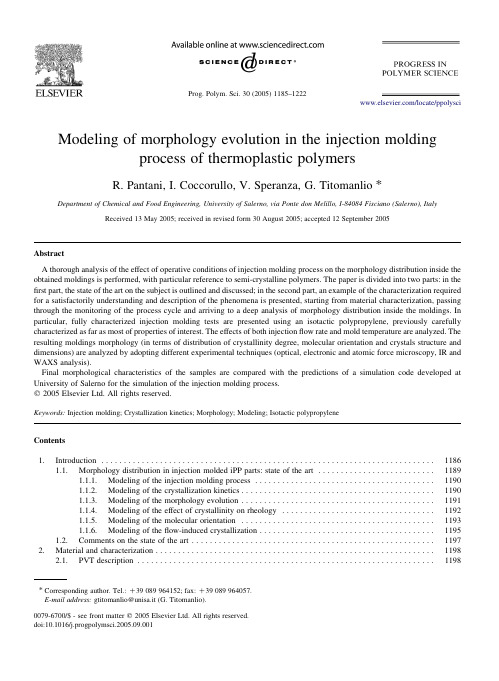
Modeling of morphology evolution in the injection moldingprocess of thermoplastic polymersR.Pantani,I.Coccorullo,V.Speranza,G.Titomanlio* Department of Chemical and Food Engineering,University of Salerno,via Ponte don Melillo,I-84084Fisciano(Salerno),Italy Received13May2005;received in revised form30August2005;accepted12September2005AbstractA thorough analysis of the effect of operative conditions of injection molding process on the morphology distribution inside the obtained moldings is performed,with particular reference to semi-crystalline polymers.The paper is divided into two parts:in the first part,the state of the art on the subject is outlined and discussed;in the second part,an example of the characterization required for a satisfactorily understanding and description of the phenomena is presented,starting from material characterization,passing through the monitoring of the process cycle and arriving to a deep analysis of morphology distribution inside the moldings.In particular,fully characterized injection molding tests are presented using an isotactic polypropylene,previously carefully characterized as far as most of properties of interest.The effects of both injectionflow rate and mold temperature are analyzed.The resulting moldings morphology(in terms of distribution of crystallinity degree,molecular orientation and crystals structure and dimensions)are analyzed by adopting different experimental techniques(optical,electronic and atomic force microscopy,IR and WAXS analysis).Final morphological characteristics of the samples are compared with the predictions of a simulation code developed at University of Salerno for the simulation of the injection molding process.q2005Elsevier Ltd.All rights reserved.Keywords:Injection molding;Crystallization kinetics;Morphology;Modeling;Isotactic polypropyleneContents1.Introduction (1186)1.1.Morphology distribution in injection molded iPP parts:state of the art (1189)1.1.1.Modeling of the injection molding process (1190)1.1.2.Modeling of the crystallization kinetics (1190)1.1.3.Modeling of the morphology evolution (1191)1.1.4.Modeling of the effect of crystallinity on rheology (1192)1.1.5.Modeling of the molecular orientation (1193)1.1.6.Modeling of theflow-induced crystallization (1195)ments on the state of the art (1197)2.Material and characterization (1198)2.1.PVT description (1198)*Corresponding author.Tel.:C39089964152;fax:C39089964057.E-mail address:gtitomanlio@unisa.it(G.Titomanlio).2.2.Quiescent crystallization kinetics (1198)2.3.Viscosity (1199)2.4.Viscoelastic behavior (1200)3.Injection molding tests and analysis of the moldings (1200)3.1.Injection molding tests and sample preparation (1200)3.2.Microscopy (1202)3.2.1.Optical microscopy (1202)3.2.2.SEM and AFM analysis (1202)3.3.Distribution of crystallinity (1202)3.3.1.IR analysis (1202)3.3.2.X-ray analysis (1203)3.4.Distribution of molecular orientation (1203)4.Analysis of experimental results (1203)4.1.Injection molding tests (1203)4.2.Morphology distribution along thickness direction (1204)4.2.1.Optical microscopy (1204)4.2.2.SEM and AFM analysis (1204)4.3.Morphology distribution alongflow direction (1208)4.4.Distribution of crystallinity (1210)4.4.1.Distribution of crystallinity along thickness direction (1210)4.4.2.Crystallinity distribution alongflow direction (1212)4.5.Distribution of molecular orientation (1212)4.5.1.Orientation along thickness direction (1212)4.5.2.Orientation alongflow direction (1213)4.5.3.Direction of orientation (1214)5.Simulation (1214)5.1.Pressure curves (1215)5.2.Morphology distribution (1215)5.3.Molecular orientation (1216)5.3.1.Molecular orientation distribution along thickness direction (1216)5.3.2.Molecular orientation distribution alongflow direction (1216)5.3.3.Direction of orientation (1217)5.4.Crystallinity distribution (1217)6.Conclusions (1217)References (1219)1.IntroductionInjection molding is one of the most widely employed methods for manufacturing polymeric products.Three main steps are recognized in the molding:filling,packing/holding and cooling.During thefilling stage,a hot polymer melt rapidlyfills a cold mold reproducing a cavity of the desired product shape. During the packing/holding stage,the pressure is raised and extra material is forced into the mold to compensate for the effects that both temperature decrease and crystallinity development determine on density during solidification.The cooling stage starts at the solidification of a thin section at cavity entrance (gate),starting from that instant no more material can enter or exit from the mold impression and holding pressure can be released.When the solid layer on the mold surface reaches a thickness sufficient to assure required rigidity,the product is ejected from the mold.Due to the thermomechanical history experienced by the polymer during processing,macromolecules in injection-molded objects present a local order.This order is referred to as‘morphology’which literally means‘the study of the form’where form stands for the shape and arrangement of parts of the object.When referred to polymers,the word morphology is adopted to indicate:–crystallinity,which is the relative volume occupied by each of the crystalline phases,including mesophases;–dimensions,shape,distribution and orientation of the crystallites;–orientation of amorphous phase.R.Pantani et al./Prog.Polym.Sci.30(2005)1185–1222 1186R.Pantani et al./Prog.Polym.Sci.30(2005)1185–12221187Apart from the scientific interest in understandingthe mechanisms leading to different order levels inside a polymer,the great technological importance of morphology relies on the fact that polymer character-istics (above all mechanical,but also optical,electrical,transport and chemical)are to a great extent affected by morphology.For instance,crystallinity has a pro-nounced effect on the mechanical properties of the bulk material since crystals are generally stiffer than amorphous material,and also orientation induces anisotropy and other changes in mechanical properties.In this work,a thorough analysis of the effect of injection molding operative conditions on morphology distribution in moldings with particular reference to crystalline materials is performed.The aim of the paper is twofold:first,to outline the state of the art on the subject;second,to present an example of the characterization required for asatisfactorilyR.Pantani et al./Prog.Polym.Sci.30(2005)1185–12221188understanding and description of the phenomena, starting from material description,passing through the monitoring of the process cycle and arriving to a deep analysis of morphology distribution inside the mold-ings.To these purposes,fully characterized injection molding tests were performed using an isotactic polypropylene,previously carefully characterized as far as most of properties of interest,in particular quiescent nucleation density,spherulitic growth rate and rheological properties(viscosity and relaxation time)were determined.The resulting moldings mor-phology(in terms of distribution of crystallinity degree, molecular orientation and crystals structure and dimensions)was analyzed by adopting different experimental techniques(optical,electronic and atomic force microscopy,IR and WAXS analysis).Final morphological characteristics of the samples were compared with the predictions of a simulation code developed at University of Salerno for the simulation of the injection molding process.The effects of both injectionflow rate and mold temperature were analyzed.1.1.Morphology distribution in injection molded iPP parts:state of the artFrom many experimental observations,it is shown that a highly oriented lamellar crystallite microstructure, usually referred to as‘skin layer’forms close to the surface of injection molded articles of semi-crystalline polymers.Far from the wall,the melt is allowed to crystallize three dimensionally to form spherulitic structures.Relative dimensions and morphology of both skin and core layers are dependent on local thermo-mechanical history,which is characterized on the surface by high stress levels,decreasing to very small values toward the core region.As a result,the skin and the core reveal distinct characteristics across the thickness and also along theflow path[1].Structural and morphological characterization of the injection molded polypropylene has attracted the interest of researchers in the past three decades.In the early seventies,Kantz et al.[2]studied the morphology of injection molded iPP tensile bars by using optical microscopy and X-ray diffraction.The microscopic results revealed the presence of three distinct crystalline zones on the cross-section:a highly oriented non-spherulitic skin;a shear zone with molecular chains oriented essentially parallel to the injection direction;a spherulitic core with essentially no preferred orientation.The X-ray diffraction studies indicated that the skin layer contains biaxially oriented crystallites due to the biaxial extensionalflow at theflow front.A similar multilayered morphology was also reported by Menges et al.[3].Later on,Fujiyama et al.[4] investigated the skin–core morphology of injection molded iPP samples using X-ray Small and Wide Angle Scattering techniques,and suggested that the shear region contains shish–kebab structures.The same shish–kebab structure was observed by Wenig and Herzog in the shear region of their molded samples[5].A similar investigation was conducted by Titomanlio and co-workers[6],who analyzed the morphology distribution in injection moldings of iPP. They observed a skin–core morphology distribution with an isotropic spherulitic core,a skin layer characterized by afine crystalline structure and an intermediate layer appearing as a dark band in crossed polarized light,this layer being characterized by high crystallinity.Kalay and Bevis[7]pointed out that,although iPP crystallizes essentially in the a-form,a small amount of b-form can be found in the skin layer and in the shear region.The amount of b-form was found to increase by effect of high shear rates[8].A wide analysis on the effect of processing conditions on the morphology of injection molded iPP was conducted by Viana et al.[9]and,more recently, by Mendoza et al.[10].In particular,Mendoza et al. report that the highest level of crystallinity orientation is found inside the shear zone and that a high level of orientation was also found in the skin layer,with an orientation angle tilted toward the core.It is rather difficult to theoretically establish the relationship between the observed microstructure and processing conditions.Indeed,a model of the injection molding process able to predict morphology distribution in thefinal samples is not yet available,even if it would be of enormous strategic importance.This is mainly because a complete understanding of crystallization kinetics in processing conditions(high cooling rates and pressures,strong and complexflowfields)has not yet been reached.In this section,the most relevant aspects for process modeling and morphology development are identified. In particular,a successful path leading to a reliable description of morphology evolution during polymer processing should necessarily pass through:–a good description of morphology evolution under quiescent conditions(accounting all competing crystallization processes),including the range of cooling rates characteristic of processing operations (from1to10008C/s);R.Pantani et al./Prog.Polym.Sci.30(2005)1185–12221189–a description capturing the main features of melt morphology(orientation and stretch)evolution under processing conditions;–a good coupling of the two(quiescent crystallization and orientation)in order to capture the effect of crystallinity on viscosity and the effect offlow on crystallization kinetics.The points listed above outline the strategy to be followed in order to achieve the basic understanding for a satisfactory description of morphology evolution during all polymer processing operations.In the following,the state of art for each of those points will be analyzed in a dedicated section.1.1.1.Modeling of the injection molding processThefirst step in the prediction of the morphology distribution within injection moldings is obviously the thermo-mechanical simulation of the process.Much of the efforts in the past were focused on the prediction of pressure and temperature evolution during the process and on the prediction of the melt front advancement [11–15].The simulation of injection molding involves the simultaneous solution of the mass,energy and momentum balance equations.Thefluid is non-New-tonian(and viscoelastic)with all parameters dependent upon temperature,pressure,crystallinity,which are all function of pressibility cannot be neglected as theflow during the packing/holding step is determined by density changes due to temperature, pressure and crystallinity evolution.Indeed,apart from some attempts to introduce a full 3D approach[16–19],the analysis is currently still often restricted to the Hele–Shaw(or thinfilm) approximation,which is warranted by the fact that most injection molded parts have the characteristic of being thin.Furthermore,it is recognized that the viscoelastic behavior of the polymer only marginally influences theflow kinematics[20–22]thus the melt is normally considered as a non-Newtonian viscousfluid for the description of pressure and velocity gradients evolution.Some examples of adopting a viscoelastic constitutive equation in the momentum balance equations are found in the literature[23],but the improvements in accuracy do not justify a considerable extension of computational effort.It has to be mentioned that the analysis of some features of kinematics and temperature gradients affecting the description of morphology need a more accurate description with respect to the analysis of pressure distributions.Some aspects of the process which were often neglected and may have a critical importance are the description of the heat transfer at polymer–mold interface[24–26]and of the effect of mold deformation[24,27,28].Another aspect of particular interest to the develop-ment of morphology is the fountainflow[29–32], which is often neglected being restricted to a rather small region at theflow front and close to the mold walls.1.1.2.Modeling of the crystallization kineticsIt is obvious that the description of crystallization kinetics is necessary if thefinal morphology of the molded object wants to be described.Also,the development of a crystalline degree during the process influences the evolution of all material properties like density and,above all,viscosity(see below).Further-more,crystallization kinetics enters explicitly in the generation term of the energy balance,through the latent heat of crystallization[26,33].It is therefore clear that the crystallinity degree is not only a result of simulation but also(and above all)a phenomenon to be kept into account in each step of process modeling.In spite of its dramatic influence on the process,the efforts to simulate the injection molding of semi-crystalline polymers are crude in most of the commercial software for processing simulation and rather scarce in the fleur and Kamal[34],Papatanasiu[35], Titomanlio et al.[15],Han and Wang[36],Ito et al.[37],Manzione[38],Guo and Isayev[26],and Hieber [25]adopted the following equation(Kolmogoroff–Avrami–Evans,KAE)to predict the development of crystallinityd xd tZð1K xÞd d cd t(1)where x is the relative degree of crystallization;d c is the undisturbed volume fraction of the crystals(if no impingement would occur).A significant improvement in the prediction of crystallinity development was introduced by Titoman-lio and co-workers[39]who kept into account the possibility of the formation of different crystalline phases.This was done by assuming a parallel of several non-interacting kinetic processes competing for the available amorphous volume.The evolution of each phase can thus be described byd x id tZð1K xÞd d c id t(2)where the subscript i stands for a particular phase,x i is the relative degree of crystallization,x ZPix i and d c iR.Pantani et al./Prog.Polym.Sci.30(2005)1185–1222 1190is the expectancy of volume fraction of each phase if no impingement would occur.Eq.(2)assumes that,for each phase,the probability of the fraction increase of a single crystalline phase is simply the product of the rate of growth of the corresponding undisturbed volume fraction and of the amount of available amorphous fraction.By summing up the phase evolution equations of all phases(Eq.(2))over the index i,and solving the resulting differential equation,one simply obtainsxðtÞZ1K exp½K d cðtÞ (3)where d c Z Pid c i and Eq.(1)is recovered.It was shown by Coccorullo et al.[40]with reference to an iPP,that the description of the kinetic competition between phases is crucial to a reliable prediction of solidified structures:indeed,it is not possible to describe iPP crystallization kinetics in the range of cooling rates of interest for processing(i.e.up to several hundreds of8C/s)if the mesomorphic phase is neglected:in the cooling rate range10–1008C/s, spherulite crystals in the a-phase are overcome by the formation of the mesophase.Furthermore,it has been found that in some conditions(mainly at pressures higher than100MPa,and low cooling rates),the g-phase can also form[41].In spite of this,the presence of different crystalline phases is usually neglected in the literature,essentially because the range of cooling rates investigated for characterization falls in the DSC range (well lower than typical cooling rates of interest for the process)and only one crystalline phase is formed for iPP at low cooling rates.It has to be noticed that for iPP,which presents a T g well lower than ambient temperature,high values of crystallinity degree are always found in solids which passed through ambient temperature,and the cooling rate can only determine which crystalline phase forms, roughly a-phase at low cooling rates(below about 508C/s)and mesomorphic phase at higher cooling rates.The most widespread approach to the description of kinetic constant is the isokinetic approach introduced by Nakamura et al.According to this model,d c in Eq.(1)is calculated asd cðtÞZ ln2ðt0KðTðsÞÞd s2 435n(4)where K is the kinetic constant and n is the so-called Avrami index.When introduced as in Eq.(4),the reciprocal of the kinetic constant is a characteristic time for crystallization,namely the crystallization half-time, t05.If a polymer is cooled through the crystallization temperature,crystallization takes place at the tempera-ture at which crystallization half-time is of the order of characteristic cooling time t q defined ast q Z D T=q(5) where q is the cooling rate and D T is a temperature interval over which the crystallization kinetic constant changes of at least one order of magnitude.The temperature dependence of the kinetic constant is modeled using some analytical function which,in the simplest approach,is described by a Gaussian shaped curve:KðTÞZ K0exp K4ln2ðT K T maxÞ2D2(6)The following Hoffman–Lauritzen expression[42] is also commonly adopted:K½TðtÞ Z K0exp KUÃR$ðTðtÞK T NÞ!exp KKÃ$ðTðtÞC T mÞ2TðtÞ2$ðT m K TðtÞÞð7ÞBoth equations describe a bell shaped curve with a maximum which for Eq.(6)is located at T Z T max and for Eq.(7)lies at a temperature between T m(the melting temperature)and T N(which is classically assumed to be 308C below the glass transition temperature).Accord-ing to Eq.(7),the kinetic constant is exactly zero at T Z T m and at T Z T N,whereas Eq.(6)describes a reduction of several orders of magnitude when the temperature departs from T max of a value higher than2D.It is worth mentioning that only three parameters are needed for Eq.(6),whereas Eq.(7)needs the definition offive parameters.Some authors[43,44]couple the above equations with the so-called‘induction time’,which can be defined as the time the crystallization process starts, when the temperature is below the equilibrium melting temperature.It is normally described as[45]Dt indDtZðT0m K TÞat m(8)where t m,T0m and a are material constants.It should be mentioned that it has been found[46,47]that there is no need to explicitly incorporate an induction time when the modeling is based upon the KAE equation(Eq.(1)).1.1.3.Modeling of the morphology evolutionDespite of the fact that the approaches based on Eq.(4)do represent a significant step toward the descriptionR.Pantani et al./Prog.Polym.Sci.30(2005)1185–12221191of morphology,it has often been pointed out in the literature that the isokinetic approach on which Nakamura’s equation (Eq.(4))is based does not describe details of structure formation [48].For instance,the well-known experience that,with many polymers,the number of spherulites in the final solid sample increases strongly with increasing cooling rate,is indeed not taken into account by this approach.Furthermore,Eq.(4)describes an increase of crystal-linity (at constant temperature)depending only on the current value of crystallinity degree itself,whereas it is expected that the crystallization rate should depend also on the number of crystalline entities present in the material.These limits are overcome by considering the crystallization phenomenon as the consequence of nucleation and growth.Kolmogoroff’s model [49],which describes crystallinity evolution accounting of the number of nuclei per unit volume and spherulitic growth rate can then be applied.In this case,d c in Eq.(1)is described asd ðt ÞZ C m ðt 0d N ðs Þd s$ðt sG ðu Þd u 2435nd s (9)where C m is a shape factor (C 3Z 4/3p ,for spherical growth),G (T (t ))is the linear growth rate,and N (T (t ))is the nucleation density.The following Hoffman–Lauritzen expression is normally adopted for the growth rateG ½T ðt Þ Z G 0exp KUR $ðT ðt ÞK T N Þ!exp K K g $ðT ðt ÞC T m Þ2T ðt Þ2$ðT m K T ðt ÞÞð10ÞEqs.(7)and (10)have the same form,however the values of the constants are different.The nucleation mechanism can be either homo-geneous or heterogeneous.In the case of heterogeneous nucleation,two equations are reported in the literature,both describing the nucleation density as a function of temperature [37,50]:N ðT ðt ÞÞZ N 0exp ½j $ðT m K T ðt ÞÞ (11)N ðT ðt ÞÞZ N 0exp K 3$T mT ðt ÞðT m K T ðt ÞÞ(12)In the case of homogeneous nucleation,the nucleation rate rather than the nucleation density is function of temperature,and a Hoffman–Lauritzen expression isadoptedd N ðT ðt ÞÞd t Z N 0exp K C 1ðT ðt ÞK T N Þ!exp KC 2$ðT ðt ÞC T m ÞT ðt Þ$ðT m K T ðt ÞÞð13ÞConcentration of nucleating particles is usually quite significant in commercial polymers,and thus hetero-geneous nucleation becomes the dominant mechanism.When Kolmogoroff’s approach is followed,the number N a of active nuclei at the end of the crystal-lization process can be calculated as [48]N a ;final Zðt final 0d N ½T ðs Þd sð1K x ðs ÞÞd s (14)and the average dimension of crystalline structures can be attained by geometrical considerations.Pantani et al.[51]and Zuidema et al.[22]exploited this method to describe the distribution of crystallinity and the final average radius of the spherulites in injection moldings of polypropylene;in particular,they adopted the following equationR Z ffiffiffiffiffiffiffiffiffiffiffiffiffiffiffiffiffiffiffi3x a ;final 4p N a ;final 3s (15)A different approach is also present in the literature,somehow halfway between Nakamura’s and Kolmo-goroff’s models:the growth rate (G )and the kinetic constant (K )are described independently,and the number of active nuclei (and consequently the average dimensions of crystalline entities)can be obtained by coupling Eqs.(4)and (9)asN a ðT ÞZ 3ln 24p K ðT ÞG ðT Þ 3(16)where heterogeneous nucleation and spherical growth is assumed (Avrami’s index Z 3).Guo et al.[43]adopted this approach to describe the dimensions of spherulites in injection moldings of polypropylene.1.1.4.Modeling of the effect of crystallinity on rheology As mentioned above,crystallization has a dramatic influence on material viscosity.This phenomenon must obviously be taken into account and,indeed,the solidification of a semi-crystalline material is essen-tially caused by crystallization rather than by tempera-ture in normal processing conditions.Despite of the importance of the subject,the relevant literature on the effect of crystallinity on viscosity isR.Pantani et al./Prog.Polym.Sci.30(2005)1185–12221192rather scarce.This might be due to the difficulties in measuring simultaneously rheological properties and crystallinity evolution during the same tests.Apart from some attempts to obtain simultaneous measure-ments of crystallinity and viscosity by special setups [52,53],more often viscosity and crystallinity are measured during separate tests having the same thermal history,thus greatly simplifying the experimental approach.Nevertheless,very few works can be retrieved in the literature in which(shear or complex) viscosity can be somehow linked to a crystallinity development.This is the case of Winter and co-workers [54],Vleeshouwers and Meijer[55](crystallinity evolution can be drawn from Swartjes[56]),Boutahar et al.[57],Titomanlio et al.[15],Han and Wang[36], Floudas et al.[58],Wassner and Maier[59],Pantani et al.[60],Pogodina et al.[61],Acierno and Grizzuti[62].All the authors essentially agree that melt viscosity experiences an abrupt increase when crystallinity degree reaches a certain‘critical’value,x c[15]. However,little agreement is found in the literature on the value of this critical crystallinity degree:assuming that x c is reached when the viscosity increases of one order of magnitude with respect to the molten state,it is found in the literature that,for iPP,x c ranges from a value of a few percent[15,62,60,58]up to values of20–30%[58,61]or even higher than40%[59,54,57].Some studies are also reported on the secondary effects of relevant variables such as temperature or shear rate(or frequency)on the dependence of crystallinity on viscosity.As for the effect of temperature,Titomanlio[15]found for an iPP that the increase of viscosity for the same crystallinity degree was higher at lower temperatures,whereas Winter[63] reports the opposite trend for a thermoplastic elasto-meric polypropylene.As for the effect of shear rate,a general agreement is found in the literature that the increase of viscosity for the same crystallinity degree is lower at higher deformation rates[62,61,57].Essentially,the equations adopted to describe the effect of crystallinity on viscosity of polymers can be grouped into two main categories:–equations based on suspensions theories(for a review,see[64]or[65]);–empirical equations.Some of the equations adopted in the literature with regard to polymer processing are summarized in Table1.Apart from Eq.(17)adopted by Katayama and Yoon [66],all equations predict a sharp increase of viscosity on increasing crystallinity,sometimes reaching infinite (Eqs.(18)and(21)).All authors consider that the relevant variable is the volume occupied by crystalline entities(i.e.x),even if the dimensions of the crystals should reasonably have an effect.1.1.5.Modeling of the molecular orientationOne of the most challenging problems to present day polymer science regards the reliable prediction of molecular orientation during transformation processes. Indeed,although pressure and velocity distribution during injection molding can be satisfactorily described by viscous models,details of the viscoelastic nature of the polymer need to be accounted for in the descriptionTable1List of the most used equations to describe the effect of crystallinity on viscosityEquation Author Derivation Parameters h=h0Z1C a0x(17)Katayama[66]Suspensions a Z99h=h0Z1=ðx K x cÞa0(18)Ziabicki[67]Empirical x c Z0.1h=h0Z1C a1expðK a2=x a3Þ(19)Titomanlio[15],also adopted byGuo[68]and Hieber[25]Empiricalh=h0Z expða1x a2Þ(20)Shimizu[69],also adopted byZuidema[22]and Hieber[25]Empiricalh=h0Z1Cðx=a1Þa2=ð1Kðx=a1Þa2Þ(21)Tanner[70]Empirical,basedon suspensionsa1Z0.44for compact crystallitesa1Z0.68for spherical crystallitesh=h0Z expða1x C a2x2Þ(22)Han[36]Empiricalh=h0Z1C a1x C a2x2(23)Tanner[71]Empirical a1Z0.54,a2Z4,x!0.4h=h0Zð1K x=a0ÞK2(24)Metzner[65],also adopted byTanner[70]Suspensions a Z0.68for smooth spheresR.Pantani et al./Prog.Polym.Sci.30(2005)1185–12221193。
SPECIAL REPORT Diagnosis of arrhythmogenic right ventricularcardiomyopathy/dysplasiaProposed Modification of the Task Force CriteriaFrank I.Marcus1*Chair,William J.McKenna2Co-Chair,Duane Sherrill1,Cristina Basso3,Barbara Bauce3,David A.Bluemke4,Hugh Calkins5,Domenico Corrado3,Moniek G.P.J.Cox6,James P.Daubert7,Guy Fontaine10,Kathleen Gear1,Richard Hauer6,Andrea Nava3,Michael H.Picard11,Nikos Protonotarios13,Jeffrey E.Saffitz12,Danita M.Yoerger Sanborn11,Jonathan S.Steinberg9,Harikrishna Tandri5,Gaetano Thiene3,Jeffrey A.Towbin14, Adalena Tsatsopoulou13,Thomas Wichter15,and Wojciech Zareba81University of Arizona,Tucson,AZ;2The Heart Hospital,London,United Kingdom;3University of Padua Medical School,Padua,Italy;4National Institutes of Health,Clinical Center, Bethesda;5Johns Hopkins Hospital,Baltimore,MD;6University Medical Center Utrecht,Utrecht,The Netherlands;7Strong Memorial Hospital,Rochester,NY;8University ofRochester Medical Center,Rochester,NY;9St.Luke’s-Roosevelt Hospital Center,New York,NY;10Hopital La Salpetriere,Paris,France;11Massachusetts General Hospital,Boston,MA;12Beth Israel Deaconess Medical Center,Boston,MA;13Yannis Protonotarios Medical Centre,Hora Naxos,Greece;14Cincinnati Children’s Hospital,Cincinnati,OH;and15Marienhospital Osnabru¨ck,Osnabru¨ck,GermanyOnline publish-ahead-of-print19February2010This paper was guest edited by Douglas P.Zipes*Correspondence to Dr Frank I.Marcus,Sarver Heart Center,1501N Campbell,Rm5153,Box245037,Tucson,AZ.Email fmarcus@This article has been co-published in the April2010issue of Circulation(Vol.121,Issue13)&2010American Heart Association,Inc.and European Society of Cardiology.European Heart Journal(2010)31,806–814doi:10.1093/eurheartj/ehq025Downloaded fromplasia’.2Progression to more diffuse RV disease and left ventricular (LV)involvement,typically affecting the posterior lateral wall,is common.3Predominant LV disease is also recognized.4Postmor-tem diagnosis may require extensive sampling and transillumina-tion.5Disease expression is variable.In the early‘concealed phase’,individuals are often asymptomatic but may nonetheless be at risk of sudden cardiac death,notably during exertion.6In the overt‘electrical phase’,individuals present with symptomatic arrhythmias,and RV morphological abnormalities are readily dis-cernible by conventional ter,diffuse disease may result in biventricular heart failure,whereas ventricular arrhythmias may or may not be present.The ultimate phenotype may resemble dilated cardiomyopathy.Clinical manifestations vary with age and stage of disease.7ARVC/D is considered to be familial with autosomal dominant inheritance,although there are recessive forms(eg,Naxos disease,Carvajal syndrome)that are associated with a cutaneous phenotype.8,9Genetic variations have been found in the desmo-somes that are responsible for cell-to-cell binding10,11(Figure1). Seven genes have been identified that are associated with ARVC/ D:plakoglobin(JUP),12desmoplakin(DSP),13plakophilin-2 (PKP2),14desmoglein-2(DSG2),15,16desmocollin-2(DSC2),17,18 transforming growth factor beta-3(TGFß3),19and TMEM43.20 Mutations in RYR2coding the ryanodine receptor have been reported in ARVC/D in patients with an arrhythmic presentation (stress-induced bidirectional ventricular tachycardia)in the absence of significant electrocardiographic or structural abnormal-ities.At present,catecholaminergic polymorphic ventricular tachycardia is considered a disorder distinct from ARVC/D.11Pre-liminary observations suggest that the mechanical defect of the desmosomes alters function of the gap junction.Electrocardio-graphic(ECG)changes and arrhythmias may develop before histo-logical evidence of myocyte loss or clinical evidence of RV dysfunction.21,22It has been proposed that similar clinical pheno-types occur that are based on disruption of a‘final common pathway’by mutations in genes encoding proteins in the defined desmosomal pathway.23Recognition of the genetic basis of ARVC/D facilitates examination of the pathogenesis in relation to arrhythmogenesis and disease progression.24It has been suggested that patients with ARVC/D may be predis-posed or susceptible to viral myocarditis,which could lead to a decrease in cardiac function and accelerate progression of the disease.25–27The link between ARVC/D and myocarditis is still undefined.BackgroundThe original1994International Task Force criteria for the clinical diagnosis of ARVC/D were based on structural,histological, ECG,arrhythmic,and familial features of the disease28(Table1).phy.Arrhythmias of RV origin,another cardinal feature of ARVC/D,was designated a minor criterion because of its occur-rence in other diseases,particularly idiopathic RV outflow tract tachycardia.Furthermore,the1994criteria focused on RV disease manifestations and stipulated the absence of or only mildLV involvement because of the need to exclude common disorderssuch as ischemic heart disease and dilated cardiomyopathy.At the time of the publication of the original Task Force guide-lines,clinical experience with ARVC/D was dominated by sympto-matic index cases and sudden cardiac death victims–the overt or severe end of the disease spectrum.Consequently,the1994cri-teria were highly specific,but they lacked sensitivity for early and familial disease.29–31Over the past15years,additional ECG markers have been pro-posed.32–34In addition,the genetic basis of the disease has been recognized,with the potential for mutation analysis.Experiencewith quantification of imaging criteria of ARVC/D has increased,and newer imaging techniques have been introduced,such as contrast-enhanced echocardiography,3-dimensional echocardio-graphy,cardiovascular magnetic resonance with late enhancement,and electroanatomic voltage mapping.35–40Figure1The cardiac desmosome and proposed roles of the desmosome in(A)supporting structural stability through cell–cell adhesion,(B)regulating transcription of genes involved in adi-pogenesis and apoptosis,and maintaining proper electrical con-ductivity through regulation of(C)gap junctions and(D)calcium homeostasis.Dsc2indicates desmocollin-2;Dsg2, desmoglein-2;Dsp,desmoplakin;Pkg,plakoglobin;Pkp2, plakophilin-2;and PM,plasma membrane.Reprinted by per-mission from Macmillan Publishers Ltd:Nat Clin Pract CardiovascMed11,&2008.at Peking University on March 6, 2011Downloaded from.............................................................................................................................................................................................................................................................................................................................................................................................................................................................................................................................................Table 1Comparison of original and revised task force criteriaOriginal task force criteriaRevised task force criteriaI.Global or regional dysfunction and structural alterations*Major†Severe dilatation and reduction of RV ejection fraction with no (or only mild)LV impairment†Localized RV aneurysms (akinetic or dyskinetic areas with diastolic bulging)†Severe segmental dilatation of the RVBy 2D echo:†Regional RV akinesia,dyskinesia,or aneurysm †and 1of the following (end diastole):—PLAX RVOT 32mm (corrected for body size [PLAX/BSA] 19mm/m 2)—PSAX RVOT 36mm (corrected for body size [PSAX/BSA] 21mm/m 2)—or fractional area change 33%By MRI:†Regional RV akinesia or dyskinesia or dyssynchronous RV contraction †and 1of the following:—Ratio of RV end-diastolic volume to BSA 110mL/m 2(male)or 100mL/m 2(female)—or RV ejection fraction 40%By RV angiography:†Regional RV akinesia,dyskinesia,or aneurysmMinor†Mild global RV dilatation and/or ejection fraction reduction with normal LV†Mild segmental dilatation of the RV †Regional RV hypokinesiaBy 2D echo:†Regional RV akinesia or dyskinesia †and 1of the following (end diastole):—PLAX RVOT 29to ,32mm (corrected for body size [PLAX/BSA] 16to,19mm/m 2)—PSAX RVOT 32to ,36mm (corrected for body size [PSAX/BSA] 18to,21mm/m 2)—or fractional area change .33%to 40%By MRI:†Regional RV akinesia or dyskinesia or dyssynchronous RV contraction †and 1of the following:—Ratio of RV end-diastolic volume to BSA 100to ,110mL/m 2(male)or90to ,100mL/m 2(female)—or RV ejection fraction .40%to 45%II.Tissue characterization of wall Major†Fibrofatty replacement of myocardium on endomyocardial biopsy †Residual myocytes ,60%by morphometric analysis (or ,50%if estimated),with fibrous replacement of the RV free wall myocardium in 1sample,with or without fatty replacement of tissue on endomyocardial biopsyMinor†Residual myocytes 60%to 75%by morphometric analysis (or 50%to 65%if estimated),with fibrous replacement of the RV free wall myocardium in 1sample,with or without fatty replacement of tissue on endomyocardial biopsyIII.Repolarization abnormalities Major†Inverted T waves in right precordial leads (V 1,V 2,and V 3)or beyond in individuals .14years of age (in the absence of complete right bundle-branch block QRS 120ms)Minor†Inverted T waves in right precordial leads (V 2and V 3)(people age .12years,in absence of right bundle-branch block)†Inverted T waves in leads V 1and V 2in individuals .14years of age (in the absence of complete right bundle-branch block)or in V 4,V 5,or V 6†Inverted T waves in leads V 1,V 2,V 3,and V 4in individuals .14years of age in the presence of complete right bundle-branch blockContinuedF.I.Marcus et al .808at Peking University on March 6, 2011 Downloaded fromSince publication of the 1994Task Force guidelines,cardiovascu-lar evaluation of the relatives of ARVC/D index cases and,more recently,genotype–phenotype association studies have also high-lighted the shortcomings of the criteria.It is now recognized that LV involvement may occur early in the course of the diseasewith some frequency.4,41The criteria also lack sensitivity for the diagnosis of familial disease.Modifications of the original criteria have been proposed to facilitate clinical diagnosis in first-degree relatives who often have incomplete expression of the disease.42According to these recommendations,in the context of proven.............................................................................................................................................................................................................................................................................................................................................................................................................................................................................................................................................Table 1ContinuedOriginal task force criteriaRevised task force criteriaIV.Depolarization/conduction abnormalities Major†Epsilon waves or localized prolongation (.110ms)of the QRS complex in right precordial leads (V 1to V 3)†Epsilon wave (reproducible low-amplitude signals between end of QRS complex to onset of the T wave)in the right precordial leads (V 1to V 3)Minor†Late potentials (SAECG)†Late potentials by SAECG in 1of 3parameters in the absence of a QRS duration of 110ms on the standard ECG†Filtered QRS duration (fQRS) 114ms†Duration of terminal QRS ,40m V (low-amplitude signal duration) 38ms †Root-mean-square voltage of terminal 40ms 20m V†Terminal activation duration of QRS 55ms measured from the nadir of the S wave to the end of the QRS,including R 0,in V 1,V 2,or V 3,in the absence of complete right bundle-branch blockV.Arrhythmias Major†Nonsustained or sustained ventricular tachycardia of left bundle-branchmorphology with superior axis (negative or indeterminate QRS in leads II,III,and aVF and positive in lead aVL)Minor†Left bundle-branch block-type ventricular tachycardia (sustained and nonsustained)(ECG,Holter,exercise)†Frequent ventricular extrasystoles (.1000per 24hours)(Holter)†Nonsustained or sustained ventricular tachycardia of RV outflow configuration,left bundle-branch block morphology with inferior axis (positive QRS in leads II,III,and aVF and negative in lead aVL)or of unknown axis †.500ventricular extrasystoles per 24hours (Holter)VI.Family history Major†Familial disease confirmed at necropsy or surgery†ARVC/D confirmed in a first-degree relative who meets current Task Force criteria†ARVC/D confirmed pathologically at autopsy or surgery in a first-degree relative †Identification of a pathogenic mutation †categorized as associated or probably associated with ARVC/D in the patient under evaluation Minor†Family history of premature sudden death (,35years of age)due to suspected ARVC/D†Familial history (clinical diagnosis based on present criteria)†History of ARVC/D in a first-degree relative in whom it is not possible or practical to determine whether the family member meets current Task Force criteria †Premature sudden death (,35years of age)due to suspected ARVC/D in a first-degree relative†ARVC/D confirmed pathologically or by current Task Force Criteria in second-degree relativePLAX indicates parasternal long-axis view;RVOT,RV outflow tract;BSA,body surface area;PSAX,parasternal short-axis view;aVF,augmented voltage unipolar left foot lead;and aVL,augmented voltage unipolar left arm lead.Diagnostic terminology for original criteria:This diagnosis is fulfilled by the presence of 2major,or 1major plus 2minor criteria or 4minor criteria from different groups.Diagnostic terminology for revised criteria:definite diagnosis:2major or 1major and 2minor criteria or 4minor from different categories;borderline:1major and 1minor or 3minor criteria from different categories;possible:1major or 2minor criteria from different categories.*Hypokinesis is not included in this or subsequent definitions of RV regional wall motion abnormalities for the proposed modified criteria.†A pathogenic mutation is a DNA alteration associated with ARVC/D that alters or is expected to alter the encoded protein,is unobserved or rare in a large non-ARVC/D control population,and either alters or is predicted to alter the structure or function of the protein or has demonstrated linkage to the disease phenotype in a conclusive pedigree.Diagnosis of arrhythmogenic right ventricular cardiomyopathy/dysplasia809at Peking University on March 6, 2011 Downloaded fromis based on the documentation of one of the following in a family member:(1)T-wave inversion in right precordial leads V1,V2,and V3inindividuals over the age of14years.(2)Late potentials by signal-averaged ECG(SAECG).(3)Ventricular tachycardia of left bundle-branch block mor-phology on ECG,Holter monitor,or during exercise testing or.200premature ventricular contractions in24hours. (4)Either mild global dilatation or reduction in RV ejection frac-tion with normal LV or mild segmental dilatation of the RV or regional RV hypokinesis.Revision of the diagnostic criteria is important to provide guidance on the role of emerging diagnostic modalities and to recognize advances in the genetics of ARVC/D.The criteria have been modi-fied to incorporate new knowledge and technology to improve diagnostic sensitivity,but with the important requisite of maintain-ing diagnostic specificity,and they include quantitative parameters for Task Force criteria,particularly for the imaging studies (Table1).The approach of classifying structural,histological, ECG,arrhythmic,and genetic features of the disease as major and minor criteria has been maintained.MethodsA limitation of the previous Task Force criteria was the reliance on subjective criteria for assessing ventricular structure and function and for evaluation of myocardial histology.In this modification of the Task Force criteria,quantitative criteria are proposed and abnormalities are defined on the basis of comparison with normal subject data(Table1).The data from108probands with newly diagnosed ARVC/D,age 12years,who were enrolled in the National Institutes of Health-supported Multidisciplinary Study of Right Ventricular Dysplasia,43were compared with those of normal subjects(online-only Data Supplement).The cri-teria were selected on the basis of analysis of sensitivity and speci-ficity from receiver operating characteristic curves.For analysis of each test[e.g.echocardiogram,magnetic resonance imaging (MRI)],proband data were excluded if that test was crucial for the diagnosis of the individual patient.This was done to eliminate bias in estimating the sensitivity and specificity of that particular test.In general,when determining the sensitivity and specificity of a new screening test,it is recommended that none of the screening test elements be used in making the primary diagnosis; this principle also holds when establishing diagnostic criteria. ResultsThere were44proband MRIs compared with462MRIs of normal subjects,69proband echocardiograms compared with450echo-cardiograms of normal subjects,69proband SAECGs compared with103SAECGs of normal subjects,and68proband Holters compared with398Holters of normal subjects.The minor criteria for echocardiography were selected where specificity and sensi-tivity are equal(sensitivity equals specificity)(Table2).The major criteria were selected as the value that yielded95%specificity.Sen-sitivity and specificity for the MRI criteria were made RV end-diastolic volume indexed to body surface area(size)andRV ejection fraction(function)simultaneously by using the OR logistical function.If either RV size or function was positive in con-junction with RV wall motion abnormality,then the subject wouldbe classified as having a major criterion for the MRI.The sensitivityof RV size alone or function alone ranged from41%to50%formajor criteria and31%to41%for minor criteria,with specificityof96%to100%.Using the OR logistical function improved the sensitivity of the MRI to79%to89%for major criteria and68%to78%for minor criteria.The original Task Force criteria list late potentials as a minor cri-terion.It has become common practice,though not based on evi-dence,to state that the SAECG is positive if2of the following3 parameters are abnormal:filtered QRS duration(fQRS),root-mean square voltage of the terminal40ms of the QRS,or durationof the terminal QRS signal,40m V.Analysis of each of the single parameters of the SAECG with late potentials by using a40-to250-Hzfilter had a sensitivity ranging from58%to60%,with aspecificity of94%to96%.Two of three parameters had a sensi-tivity of66%and specificity of95%,adding little advantage withregard to sensitivity and specifiing any one of the3 SAECG parameters had a sensitivity of74%and specificity of92%.A definitive diagnosis of ARVC/D is based on histological dem-onstration of transmuralfibrofatty replacement of RV myocardiumat biopsy(Figure2),necropsy,or surgery.5,44In most patients, however,assessment of transmural myocardium is not possible.In addition,diagnosis based on RV endomyocardial biopsy speci-mens is limited because the segmental nature of the disease causes false e of electroanatomic voltage mappingto identify pathological areas for biopsy sampling may improvethe yield.45RV free wall biopsy has a slight risk of perforation,but the more accessible interventricular septum rarely exhibits his-tological changes.Nevertheless,endomyocardial biopsy may ident-ify other conditions(e.g.myocarditis,sarcoidosis,endomyocardialfibrosis),and the recognition of myocyte loss withfibrous orfibro-fatty replacement can be a valuable diagnostic feature.46The identification of disease-causing genes has led to the recognition of a broader spectrum of disease expression within families,including individuals who have predominantly LV disease, manifest clinically by inferolateral T-wave changes,ventricular ectopy,or ventricular tachycardia with right bundle-branch block morphology and epicardial or midmyocardial late enhancementby MRI.4,7,38,39,41The importance of familial disease highlights arole for mutation analysis of probands with cascade screening of relatives that offers an alternative strategy to serial noninvasive car-diovascular evaluation of families.A positive diagnosis in a family member changes the probability of disease in an individual sus-pected of the disease to1:2from1:1000to1:5000.Thus,con-firmed disease in afirst degree relative is a major criterion for diagnosis.42DiscussionThe diagnosis of ARVC/D relies on the demonstration of struc-tural,functional,and electrophysiological abnormalities that are caused by or reflect the underlying histological changes.Technical advances in MRI and2-dimensional echocardiography haveat Peking University on March 6, 2011Downloaded fromimproved the capability to image the RV with reproducible measure-ments of volume and systolic function,which permits classification of severity and differentiation from normality 47(Table 2).Previous diag-nostic reliance on subjective assessment of RV wall thinning,wall motion abnormalities,and fatty infiltration of the myocardium byMRI has proven problematic.48,49Recognition of significant fatty involvement without concomitant fibrosis of the RV in normal indi-viduals renders this unique MRI capability of limited te enhancement on MRI permits myocardial tissue characterization in the LV.It can be difficult to be certain of late enhancement for..............................................................................................................................................................................................................................................................................................................................................................Table 2Sensitivity and specificity of proposed RV imaging criteria*ValueSensitivity,%Specificity,%EchocardiogramMajorPLAX RVOT (diastole)32mm 7595Corrected for body size (PLAX/BSA) 19mm/m2PSAX RVOT (diastole)36mm 6295Corrected for body size (PSAX/BSA) 21mm/m 2Fractional area change 33%5595MinorPLAX RVOT (diastole)29mm8787Corrected for body size (PLAX/BSA) 16to 18mm/m 2iPSAX RVOT (diastole)32mm8080Corrected for body size (PSAX/BSA) 18to 20mm/m 2Fractional area change 40%7676MRI †MajorRatio of RV end-diastolic volume to BSAMales 110mL/m 2Females 100mL/m 27690F or6898CRV ejection fraction 40%MinorRatio of RV end-diastolic volume to BSAMales 100mL/m 2Females 90mL/m 27985F or8997CRV ejection fraction45%Abbreviations as in Table 1.*All the major and minor criteria listed in this table are in addition to the requirement that regional wall motion abnormalities must also be present.†The sensitivity and specificity for males and females are the same as listed if,in addition to the stated wall motion criteria,there is either abnormal RV size or function or both.Figure 2Endomyocardial biopsy findings in a proband affected by a diffuse form of ARVC/D.All 3biopsy samples are from different regionsof the RV free wall.There is extensive fibrofatty tissue replacement with myocardial atrophy,which is a major criterion (i.e.residual myocytes ,60%by morphometric analysis or ,50%if estimated).Contributed by C.Basso,Padua,Italy.Diagnosis of arrhythmogenic right ventricular cardiomyopathy/dysplasia811at Peking University on March 6, 2011 Downloaded fromcharacterization of RV myocardium because of the thin wall of the RV and possible confusion with fat.50There also have been recent developments to quantify the extent of RV wall motion abnormalities by angiography with computer-based analysis,as well as to determine RV volumes.51,52In addition,commercial software is available to deter-mine RV volumes and ejection fraction.53The RV angiogram obtained in multiple views is considered to be a reliable imaging test to assess wall motion abnormalities but requires considerable experience.Standardized protocols for performance of these diag-nostic studies (ECG,SAECG,echocardiogram,RV angiogram,and MRI)are available on .Repolarization abnormalities are early and sensitive markers of disease expression in ARVC/D.T-wave inversion in V1,V2,and V3and beyond in individuals .14years of age who are otherwise healthy is observed in only 4%of healthy women and 1%of men.Therefore,it is reasonably specific in this population and con-sidered a major diagnostic abnormality in ARVC/D.54Depolariz-ation delay in right precordial leads is also common in ARVC/D.33,34Evaluation of the duration of terminal QRS activation (Figure 3)incorporates slurring of the S wave,as well as R 0,into a single measure of terminal activation duration.34Depolarization abnormalities cannot be evaluated in the presence of typical com-plete right bundle-branch block with terminal delay in leads I and V 6.However,T-wave inversion in V 1,V 2,V 3,and V 4is uncommon in patients with right bundle-branch block who do not have ARVC/D and is seen frequently in those who do have the disease.Con-ventional definitions are used for ventricular arrhythmias.An abnormal SAECG is based on time domain criteria with cutoffs generated from receiver operating characteristic curves.55,56The sensitivity and specificity of any one of the time domain criteria is similar to that of any 2or 3of these criteria;therefore,any one of the criteria is proposed as a criterion for this modality.The presence of left bundle-branch block ventricular tachycardia with an inferior axis (R wave positive in leads II and III and negative in lead aVL)is typical of focal RV outflow tract tachycardia.57Similar features may be seen in patients with ARVC/D but usually coexist with anterior T-wave inversion and ventricular arrhythmias of varying morphologies.The presence of ventricular ectopy increases with age,but .200ventricular premature beats in 24hours in an adult ,50years of age suggests underlying myo-cardial disease.58The revised criteria were applied post hoc to 108newly diag-nosed probands enrolled in the Multidisciplinary Study of Right Ventricular Dysplasia,a study supported by the National Institutes of Health.They had been carefully evaluated,including assessment of diagnostic tests by expert core laboratories.43Of the 73pro-bands with final classification as ‘affected’,71remain affected and 2were reclassified as borderline.The change from affected to bor-derline in the 2was due to the echocardiogram’s fulfilling only minor criteria in one and only mild hypokinesis in the angiogram of the other.Of the 28probands classified as borderline (met some but not all of the original Task Force criteria–i.e.1major and 1minor or 3minor),5remain borderline and 16were reclas-sified by the new criteria as affected.Seven became unaffected (did not meet the proposed modified Task Force criteria).Of 7pro-bands previously classified as unaffected,4remained unaffected,1became affected,and 2became borderline.Therefore,the effect of the revised criteria is to increase the sensitivity of the classification,primarily in probands previously classified as borderline.Nine of 28probands classified as borderline by original criteria had gene variants consistent with ARVC/D.The sensitivity of the revised criteria is not perfect,as exemplified by the observation that if the genetic criteria are ignored,the proposed criteria classi-fied 2as unaffected and 3remained borderline,and 4became affected.Including the proposed genetic criteria resulted in all 9being classified asaffected.Figure 3ECG from proband with T-wave inversion in V 1through V 4and prolongation of the terminal activation duration 55ms measuredfrom the nadir of the S wave to the end of the QRS complex in V 1.Contributed by M.G.P.J.Cox,Utrecht,The Netherlands.F.I.Marcus et al .812at Peking University on March 6, 2011 Downloaded from。
International Journal for Numerical in Fluids, 2011,67(9):1160-1174.[2]王兴勇,索丽生,程永光,等.用Lattice Boltzmann方法模拟方柱绕流[J].河海大学学报(自然科学版),2003, 31 ( 3 ):259-263. (WANG Xingyong,SUOLisheng,CHENG Yongguang,et al. Simulation of flowfields around a square cylinder with Lattice BoltzmannMethod [ J ]. Journal of Hohai University ( NaturalScience),2003,31(3) :259-263. (in Chinese))[3]张兰丁.桥墩群体绕流的复变函数理论解[J].水利水电科技进展,2005,25 (1 ):14-16. (ZHANG Landing.Theoretical solution of complex function about flow aroundbridge piers[J]. Advances in Science and Technology ofWater Resources,2005,25(1) :14-16. (in Chinese))[4] CAO S Y,GEY J,TAMURA Y. Shear effects on flow pasta square cylinder at moderate Reynolds numbers [ J].Journal of Engineering Mechanics,2012,138 (1): 116123.[5] LANKADASU A,VENGADESAN S. Onset of vortexshedding in planar shear flow past a square cylinder[J].International Journal of Heat and Fluid Flow,2008,29(4) :1054-1059.[ 6 ] HWANG R R, SUE Y C. Numerical simulation of shear effect on vortex shedding behind a square cylinder [J].International Journal for Numerical Methods in Fluids,1998,25(12) :1409-1420.[7] AYUKAWA K,OCHI J,HIRAO T. Effects of shear rate onthe flow around a square cylinder in a uniform shear flow[J ]. Journal of Wind Engineering and IndustrialAerodynamics,1993,50(93) :97-106.[8]陈明杰,施卫平.用格子Boltzmann方法计算剪切流的方柱绕流问题[J].吉林大学学报(理学版),2007,45(I): 11-14. ( CHENG Mingjie,SHI Weiping. Numericalsimulation of linear shear flow past a square cylinder withLattice Boltzmann method [ J] . Journal of Jilin University(Science Edition),2007,45(1) :11-14. (in Chinese)) [ 9 ] SAHA A K, BISWAS G, MURALIDHAR K. Influence of inlet shear on structure of wake behind square cylinder[J]. Journal of Engineering Mechanics,1999,125 : 359363.[10] WANG D G,WANG H J,XIONG J H,et al.Characteristic-based operator-splitting finite elementmethod for Navier-Stokes equations [ J ] . Science ChinaTechnological Sciences,2011,54(8):2157-2166. [11] BREUER M,BERNSDORF J,ZEISER T,et al. Accuratecomputations of the laminar flow past a square cylinderbased on two different methods:Lattice-Boltzmann andfinite-volume[J]. International Journal of Heat and FluidFlow,2000,21(2):186-196.[12] BREUER M,RODI W. Large eddy simulation for complexturbulent flows of practical interest [J]. Flow Simulationswith High-Performance Computer II,1996,52:258-274. [13] DAVIS R W,MOORE E F. A numerical study of vortexshedding from rectangles[J]. Journal of Fluid Mechanics,1982,116:475-506.[14] TREIDLER E B. An experimental and numericalinvestigation of flow past ribs in a channel[ R]. Berkeley:University of California,1991.[15] LI G,HUMPHREY J A C. Numerical modelling ofconfined flow past a cylinder of square cross-section atvarious orientations [ J ] . International Journal forNumerical Methods in Fluids,1995,20(21) :1215-1236.[16] ARNAL M P,GOERING D J,HUMPHREY J A C. Vortexshedding from a bluff body adjacent to a pane siding wall[ J ] . Transaction of American Society of MechanicalEngineering,1991,113(3) :384-398.[17] OKAJIMA A. Strouhal numbers of rectangular cylinders[J]. Journal of Fluid Mechanics,1982,123 :379-398. [18] CHENG M,TAN S H N,HUNG K C. Linear shear flowover a square cylinder at low Reynolds number [ J ] .Physics of Fluids,2005,17(7) :078103-1-78103^. [19] KWON T S,SUNG H J,HYUN J M,et al. Experimentalinvestigation of uniform-shear flow past a circular cylinder[J]. Journal of Fluids Engineering,1992,114(3) : 457 -460.(收稿日期:2015 - 11 -07编辑:熊水斌)•简讯•第11届水科学发展论坛将在大连举办随着自然条件的变化和人类活动的加剧,水科 学问题越来越复杂。
Flow patterns past two circular cylinders in proximityKyongjun Lee,Kyung-Soo Yang *Department of Mechanical Engineering,Inha University,253Yonghyun-Dong,Nam-Gu,Incheon 402-751,Republic of Koreaa r t i c l e i n f o Article history:Received 18February 2008Received in revised form 6June 2008Accepted 24July 2008Available online 5August 2008Keywords:Circular cylinderImmersed boundary method Flow pattern Vortex shedding Wake interactiona b s t r a c tFlow patterns past two nearby circular cylinders of equal diameter immersed in the cross-flow at low Reynolds numbers (Re 6160),were numerically studied using an immersed boundary method.We con-sidered all possible arrangements of the two cylinders in terms of the distance between the two cylinders and the inclination angle of the line connecting the cylinder centers with respect to the direction of the main flow.Ten distinct flow patterns were identified in total based on vorticity contours and streamlines,which are Steady,Near-Steady,Base-Bleed,Biased-Base-Bleed,Shear-Layer-Reattachment,Induced-Sep-aration,Vortex-Impingement,Flip-Flopping,Modulated Periodic,and Synchronized-Vortex-Shedding.Collecting all the numerical results obtained,we propose a general flow-pattern diagram for each Re ,and a contour diagram on vortex-shedding frequency for each cylinder at Re =100.The perfect symmetry implied in the geometrical configuration allows one to use these diagrams to identify flow pattern and vortex-shedding frequencies in the presence of two circular cylinders of equal diameter arbitrarily posi-tioned in physical space with respect to the main-flow direction.Ó2008Elsevier Ltd.All rights reserved.1.IntroductionCross-flow past a group of cylinders is often found in practical engineering applications.For instance,air flow past a bundle of pipes in a chemical plant,coolant flow past tubes in a heat exchan-ger,sea-water flow past columns of a marine structure,and wind past an array of chimneys of a power plant,to name a few.Flow characteristics past each cylinder are affected by its neighbors via wake interaction,resulting in alteration of the overall flow pattern.Therefore,flow pattern past multiple cylinders heavily depends on their relative positions with respect to the main-flow direction.Consequently,vortex-shedding frequency of the individual cylin-der is accordingly determined,and serves as an important factor in generation of flow noise [1].Being motivated by this,many researchers have been involved in studying wake interaction be-tween two circular cylinders of equal diameter immersed in a cross-freestream as a basic wake-interaction model.Spatial arrangement of two cylinders can be classified into three catego-ries,namely,aligned with the direction of the main flow (in tan-dem),placed side-by-side,and placed in a staggered arrangement.When two circular cylinders of equal diameter are placed side-by-side,flow pattern varies with Reynolds number (Re )and the distance between the cylinders.Kang [2]identified six distinct flow patterns depending on Re and the distance between the cylinders.It was also found that when the surface-to-surface distance is long-er than 5D (here,D is the cylinder diameter),wake interaction van-ishes and flow past each cylinder behaves just like the flow past the single cylinder placed in the freestream [2].Williamson [3]classified the types of vortex shedding by using flow visualization.When Re =100and the surface-to-surface distance is longer than D ,the flow pattern past the two cylinders is periodic,and vortex shedding from each cylinder is either in phase or out of phase by 180°with the other one.However,when the surface-to-surface distance is shorter than D ,the flow pattern past the two cylinders is non-periodic and completely irregular [2,3].When the two cylinders are placed in tandem,there exists the critical distance between the two cylinders,below which vortex shedding of the upstream cylinder (hereafter,called ‘‘main cylin-der”,MC)does not occur;the value of the critical distance varies depending on Re [4–7].Mizushima and Suehiro [4]revealed that the flow pattern with L /D =2.0is different from that with L /D =4.0at Re =100mainly due to suppression of vortex shedding from MC.Here,L denotes the streamwise distance between the two cylinder centers (Fig.1(a)).They also predicted existence of bistable solutions in the range of 3.16L /D 63.5for Re =100.Sub-sequently,Tasaka et al.[5]performed experimental investigation to verify the prediction of Mizushima and Suehiro [4],and reported 4.66L/D 65.0as the range of L /D for existence of bistable solu-tions,being shifted from the numerical prediction of Mizushima and Suehiro [4].Tasaka et al.[5]attributed the discrepancy to the finite length of the cylinders in their experiments.Carmo and Meneghini [6]investigated the three-dimensional structures be-hind two circular cylinders when they are in tandem for the range of 160<Re <320.Sharman et al.[7]performed numerical predic-*Corresponding author.Tel.:+82328607322;fax:+puters &Fluids 38(2009)778–788Contents lists available at ScienceDirectComputers &Fluidsj o u r n a l h o m e p a g e :w w w.e l s e v i e r.c o m /l o c a t e /c om p flu idrevealing a sudden change in keyflow parameters between L/D= 3.75and4.0.Sumner et al.[8,9]experimentally studiedflow-induced forces andflow patterns for high-Re(8506Re61900)flows past two cir-cular cylinders in staggered arrangements;they identified nine dis-tinctiveflow patterns.Akbari and Price[10]identifiedfive distinct flow patterns at Re=800.Gu and Sun[11]and Sun et al.[12]also reportedflow patterns in turbulentflow regime.In spite of the numerous studies carried out so far,the case where the two cylinders are placed in a staggered position has not been systematically studied,especially in the laminarflow re-gime.In this investigation,flow patterns past two nearby circular cylinders of equal diameter immersed in the cross-flow at Re6160,based on the freestream velocity(U)and D,were numer-ically studied as a basic model for laminar wake interaction.An im-mersed boundary method[13]was employed for effective treatment of the cylinders on a Cartesian grid system.We consider all possible arrangements of the two circular cylinders in terms of the distance between them and the inclination angle of the line connecting their centers with respect to the mainflow direction. The current authors recently reported their numerical results on theflow-induced forces in the sameflow setting[14].As a fol-low-up study,the present paper classifies theflow patterns ob-served,and describes distinctive characteristics of eachflow pattern.Collecting all the results obtained,we propose aflow-pat-tern diagram(‘‘map”)for prediction of theflow pattern associated with a particular arrangement of the two cylinders as well as a Strouhal-number diagram for vortex shedding of each cylinder to provide an overall picture on the wake interaction.The perfect symmetry implied in the geometrical configuration allows one to use these diagrams to identifyflow pattern and vortex-shedding frequencies in the presence of two circular cylinders of equal diam-eter arbitrarily positioned in physical space with respect to the mainflow direction.2.Formulation and numerical methodologyThe current investigation requires a parametric study where numerous numerical simulations must be performed with various values of L and T.Here,T represents the vertical distance between the two cylinder centers(Fig.1(a)).This kind of parametric study demands considerable amount of computing resources;the com-puting efforts can be significantly reduced by employing an im-mersed boundary method which facilitates implementing the solid surfaces of the arbitrarily-positioned cylinders on a Cartesian o u jo x jÀq¼0ð1Þo u iþo u i u jj¼Ào piþ1o2u ij jþf i i¼1;2ð2Þwhere u i(or u,v),p,q and f i represent velocity component in x i(or x,y)direction,pressure,mass source/sink,and momentum forcing, respectively.All the physical variables except p are non-dimension-alized by U and D;pressure is non-dimensionalized by far-field pressure(P1)and the dynamic pressure.The governing equations were discretized using afinite-volume method in a nonuniform staggered Cartesian grid system.Spatial discretization is second-or-der accurate.A hybrid scheme is used for time advancement;non-linear terms are explicitly advanced by a third-order Runge–Kutta scheme,and the other terms are implicitly advanced by the Crank–Nicolson method.A fractional step method[15]was em-ployed to decouple the continuity and momentum equations.The Poisson equation resulted from the second stage of the fractional step method was solved by a multigrid method.For detailed description of the numerical method used in the current investiga-tion,see Yang and Ferziger[16].3.Boundary conditions and numerical parametersThe main cylinder isfixed at the origin of the coordinate system, and the downstream cylinder(hereafter,called‘‘surrounding cylin-der”,SC)is placed at various locations relative to MC,which are represented by dots in Fig.1(b).The total number of cases com-puted is208for Re=100,and58for Re=40,50,and160.In the case where the center distance(R,Fig.1(a))is minimum, L/D=0.25,T/D=1.0,and the inclination angle(/,Fig.1(a))is 75.96°.The entire computational domain was defined as À35D6x635D,andÀ50D6y650D.For each cylinder,32Â32 uniform grid cells in x-and y-directions,respectively,were allo-cated,and uniform grid cells of the same cell size as in the cylinder region were employed between the cylinders.In the other region of the domain,nonuniform grid cells were used.The numerical resolution was determined by a grid-refinement study to ensure grid-independency.In the case of L/D=1.5,T/D=0.5(Fig.2),for in-stance,the total number of grid cells was368Â208,while 480Â352grid cells were allocated in the most demanding case (L/D=5.0,T/D=5.0).No-slip condition was imposed on the cylinder surfaces;a Dirichlet boundary condition(u=U,v=0)was used on theK.Lee,K.-S.Yang/Computers&Fluids38(2009)778–7887794.Verification of the codeFor verifying our numerical methodology and resolution,the flow past a single circular cylinder at Re =100was computed and our results were compared with other authors’numerical [2,18]and experimental [19]results.The size of computational domain and the boundary conditions employed were as described in the previous section.The same number of uniform grid cells (32Â32)as in the two-cylinder cases was allocated for the cylin-der,and the total numerical resolution was 320Â192.Table 1pre-sents mean drag coefficient ðC d Þ,maximum magnitude of lift-coefficient fluctuation ðC 0l ;max Þ,and Strouhal number (St )of the vor-tex shedding in the literature,along with the present results.The present results are in excellent agreement with those of other authors,verifying that the numerical scheme and resolution used in the current simulation are adequate and reliable.5.Results and discussionIn the present investigation,we classified types of flow pattern based on streamlines and contours of spanwise vorticity (x z ).Spanwise vorticity is defined as 1o v Ào u,and contour lines cover À4.06x z 64.0with increment of 0.1in the following contour plots.Solid and dashed lines represent positive and negative vor-ticity,respectively.Four different values of Re (40,50,100,and 160)were considered.For Re =100and 160,the general trend can be summarized as follows.When the two cylinders are ‘‘very”close to each other,the vortex shedding occurs as if the two cylinders were just one object.When they stand ‘‘reasonably”apart,wake interaction takes place,resulting in various types of flow pattern depending on how the two cylinders are positioned.When they are ‘‘far”away from each other,wake interaction is weak and flow characteristics around each cylinder resemble those of a single cylinder at the same Re .In the current investigation,10distinct flow patterns were identified in total for Re 6160.To name the flow patterns,weadopted the terms in the previous studies [2,9],if applicable.Otherwise,we named the new flow patterns with our own terms.In the following section,detailed description of flow patterns is gi-ven for Re =100.The effect of Re on wake interaction is addressed in Section 5.2.5.1.Classification of flow pattern for Re =1005.1.1.Base bleed (BB)BB pattern is noticed when (L /D ,T/D )=(0.0,1.25),(0.25,1.0),(0.25,1.25),(0.5,1.0),(0.75,0.75).Even though the distance be-tween the two cylinders is quite short,the flow through the ‘‘gap”is significant owing to the large /.Fig.3presents snapshots of pressure contours together with streamlines through the gap at the four selected instants with equal time interval during one per-iod of vortex shedding (T p ).Fig.4shows the corresponding time histories of drag coefficient (C d )for MC and SC,respectively.In Fig.3(a),a low pressure region is seen behind MC,attracting the gap flow into this region and also causing a high drag force on MC (see A in Fig.4).The opposite is the case in Fig.3(c);pressure is low behind SC.As a result,the gap flow is diverted towards the low pressure region (Fig.3(c)),and SC experiences a high drag force (see B in Fig.4).In Fig.5,contours of x z are presented at the same instants as in Fig.3.The short distance between the cylinders pre-vents ‘‘individual”shedding;the vortices are shed in a fashion sim-ilar to that behind a single object.5.1.2.Biased base bleed (BBB)BBB pattern is found when (L /D ,T /D )=(1.0,0.25),(1.0,0.5).The gap between the cylinders is very narrow like the BB pattern,but /is small unlike the BB pattern.Fig.6shows snapshots of instanta-neous pressure contours and streamlines through the gap at the four selected instants with equal time interval during T p .The flow through the gap is always heading downwards due to the small /(Fig.6),while in the BB pattern,the direction of the gap flow is alternating up and down (Fig.3).In Fig.7,contours of x z are shown at the same instants as in Fig.6.Like in the BB pattern,vortices are shed as if the two cylinders were just one object.5.1.3.Shear layer reattachment (SLR)SLR pattern is observed approximately when 1.256L /D 64.0,T/D 60.75;in this range,/is less than 22°.Instantaneous stream-lines of a typical case of SLR pattern (L /D =3.0,T/D =0.5)are pre-sented in Fig.8.The shear layer formed above MC reattaches on SC.A lower portion of the shear layer is deflected by SC,and to-gether with the shear layer formed below MC,surrounds the recir-culation region behind MC.In Fig.9where instantaneous contours of x z are taken at four instants with equal time interval during T p ,it is seen that SC significantly interfere with the upper shear layer from MC.It is also noticed that vortex shedding from MC has been completely suppressed by SC,and vortex shedding from SC is somewhat delayed.This is one of the important features of SLR pat-tern.Sharman et al.[7]reported that in tandem arrangements of the two cylinders,vortex shedding from MC resumes at a certain ‘‘critical”distance between them which is in the range of 3.756L /D 64.0depending on Re .5.1.4.Induced separation (IS)IS pattern is noticed approximately when 1.06L /D 63.5,0.756T /D 61.75.In this region,/is relatively large compared to that of SLR pattern.Fig.10presents instantaneous contours of x z taken at the four instants with equal time interval during T p .TheTable 1Validation of numerical method:flow past a single cylinder at Re =100ReC d C 0l ;max St 780K.Lee,K.-S.Yang /Computers &Fluids 38(2009)778–788one vortex (C in Fig.10).However,negative vortices are mainly shed from SC (Fig.10).Fig.11shows a snapshot of streamlines for L /D =1.5,T /D =1.0.The gap flow actually induces separation on SC,enhancing vortex shedding from SC.Consequently,vortex shedding from SC is much more active in IS pattern than in SLR pattern.5.1.5.Vortex impingement (VI)VI pattern appears in the range of approximately L /D P 4.0,T /D 61.75,where the two cylinders are far apart (R /D P 4.0)and /is less than 24°.When the two cylinders are placed in tandem withK.Lee,K.-S.Yang /Computers &Fluids 38(2009)778–788781a short distance between them(L/D63.75for Re=100),SC sup-presses the vortex shedding of MC[7].With a larger distance,how-ever,SC fails to suppress the vortex shedding of MC,and vortices are shed from both cylinders.Vortices of positive and negative signs, shed from MC in an alternating manner,impinge upon SC.However, when the two cylinders are slightly‘‘off-tandem”(say,T/D P0.25),shedding with equal time interval when L/D=4.0,T/D=1.0.The negative vortex which developed in the upper shear layer of MC im-pinges upon SC(A in Fig.12(a)),and then split into two parts(A0and A00in Fig.12(b)).One of them(A00)is combined with the negative vor-tex shed from SC,and the other remains as a separate secondary vor-tex(B in Fig.12(c),and C in Fig.12(d)).782K.Lee,K.-S.Yang/Computers&Fluids38(2009)778–788where the distance between the two cylinders(1.346R/D63.20) is somewhat larger than those in BB or BBB patterns,and/P38°. In this pattern,both cylinders shed vortices,yielding two pairs of counter-rotating vortices.Unlike BB or BBB pattern,however,FF pattern is irregular in time,being consistent with Meneghini et al.[20]and Kang[2].Kang reported that in side-by-side arrange-ments of two cylinders,flow pattern is irregular when1.46T/D62.2.Fig.13shows temporal variations of drag and lift coefficients(C d,C l),respectively,for L/D=0.0,T/D=2.0;irregular force coeffi-cients reflect irregularflow behavior in FF pattern.5.1.7.Modulated periodic(MP)MP pattern occurs in the range of approximately0.56L/ D63.0,T/D P2.5where the two cylinders are far apart (2.696R/D65.59),and approximately/P45°.Combination of the large distance and the relatively high inclination angle yields weak interaction between the two wakes,resulting in slight mod-ulation in vortex shedding from each cylinder.It is noticed that the vortex-shedding frequency of MC is slightly higher than that of SC.K.Lee,K.-S.Yang/Computers&Fluids38(2009)778–788783Fig.14presents temporal variation of C l for L /D =1.5,T /D =3.0,revealing modulation of amplitude and frequency of the force coef-ficient.Instantaneous contours of x z at two distinct instants are illustrated in Fig.15.It is seen that two positive vortices shed from the cylinders are side-by-side in Fig.15(a).However,the opposite is the case at a later time (Fig.15(b)),indicating the difference be-tween the two frequencies of vortex shedding.MP pattern is sim-ilar to ‘VPE’(vortex pairing and enveloping)or ‘VPSE’(vortex pairing,splitting and enveloping)patterns in Sumner et al.[9]for 8506Re 61900.5.1.8.Synchronized vortex shedding (SVS)SVS pattern is noticed in the arrangements where the two cylinders is far apart (R /D P 2.5)and /P 20°.Due to the long dis-tance and high inclination angle,the interaction of the wakes is negligible,and vortices are shed just like the single cylinder in the freestream.Fig.16shows contours of x z at four instants of equal time interval during one period of vortex shedding for L /D =0.0,T /D =3.0.The cylinders shed vortices independently;interaction of wakes such as vortex merging is hardly seen.In this particular case,the vortices from the two cylinders are out of phase by 180°owing to the perfect geometrical symmetry with respect tothe center line between the two cylinders.However,in a staggered arrangement of the cylinders,the phase difference changes,and the wake interaction is still negligible in SVS pattern.5.2.Flow patterns for low-Re flowsThe following two flow patterns are uniquely observed in low-Re flows (Re =40and 50).784K.Lee,K.-S.Yang /Computers &Fluids 38(2009)778–7885.2.1.Steady(S)In this pattern,flow is steady in the entire domain.5.2.2.Near steady(NS)NS pattern is characterized by‘‘delayed”unsteadiness.In Fig.17,streamlines are presented at four instants of equal time interval during one period of vortex shedding for L/D=0.0, T/D=1.5at Re=50.In NS pattern,flow is steady around the two cylinders,but becomes unstable in the far downstream wake.It should be noted that NS pattern is also found at Re=40which is slightly below the critical Reynolds number(Re c%43)for the sin-gle-cylinder case.5.3.Flow-pattern diagramCollecting all the results obtained,we propose theflow-pattern diagrams on L–T-plane in Fig.18to provide an overall picture on theflow patterns past two nearby circular cylinders of equal diam-eter.All the patterns discussed earlier are indicated together with their‘‘schematic”boundaries for convenience.The cases actually computed are denoted by the dots.One can identify the effect of Re by comparing the diagrams.At a subcritical Reynolds number(Re=40,Fig.18(a)),theflow would be entirely steady,if there were only single cylinder present.at Re=50which is above Re c(Fig.18(b)).FF and VI patterns do not occur in the low-Reflows.For the high Reynolds numbers(Re=100 and160),S and NS patterns are not found(Fig.18(c)and(d)).As Re increases from Re=100to Re=160,FF and VI patterns occur in more arrangements as expected.5.4.Frequency of vortex sheddingFig.19presents contour diagrams of Strouhal number(St)of vortex shedding for MC(Fig.19(a))and SC(Fig.19(b)),respec-tively,for all possible arrangements of the two cylinders at Re=100.The Strouhal number was computed based on C l using fast Fourier transform(FFT),and normalized with that of the single cylinder(St s=0.165)immersed in the freestream at Re=100.When multiple dominant frequencies were identified (for example,in FF pattern),the most dominant one was reported in Fig.19.For the main cylinder(Fig.19(a)),the maximum St(=0.204)is identified for L/D=1.0,T/D=2.0.In the range of approximately T/D P2.0,the Strouhal number of MC is larger than St s,implying that SC induces more frequent vortex shedding from MC in this region.The opposite is the case when T/D62.0because SC suppresses vortex shedding from MC.It should be noted that in the range of approximately0.06L/D62.5,1.56T/D62.0,St ofK.Lee,K.-S.Yang/Computers&Fluids38(2009)778–788785786K.Lee,K.-S.Yang/Computers&Fluids38(2009)778–788other that the‘‘effective”characteristic length scale is larger than D.As a result,the‘‘effective”Reynolds number increases and St drops.Although the distance between the cylinders is identical (R/D=1.12)in both patterns,the inclination angle in BB pattern is larger than that in BBB pattern,yielding a bigger‘‘effective”char-acteristic length,thus smaller St.In the cases of SLR,IS,and VI patterns where/645°,the Strou-hal numbers of MC and SC are identical,but smaller than St s,indi-cating strong wake interaction due to small/.Nevertheless,the Strouhal number in VI pattern is larger than those in SLR and IS patterns,and more closer to St s,which implies that wake interac-tion is rather weak in VI pattern because the two cylinders are far apart in VI pattern compared to the other two patterns.In the cases of FF and MP patterns where/is large,the Strouhal number of MC is larger than that of SC as well as St s.One can con-jecture that in these patterns,vortex shedding from MC is more en-hanced by the presence of SC via wake interaction.However,as the two cylinders become far apart and/also increases,such as in SVS pattern,the Strouhal numbers of the two cylinders become identi-cal again,and approach St s.5.5.Extension of usage of the diagrams to other arrangementsEven though the diagrams(Figs.18and19)were constructed only for one quarter of all possible arrangements of MC and SC with MCfixed at the origin,one can still use them for the other arrangements using the symmetry of the geometrical configura-tion.The constant freestream velocity allows the symmetry of SC with respect to the x-axis(Fig.20(a)).For example,when SC is placed in the fourth quadrant,the diagrams are still effective as they are,as long as the vertical distance between SC and the x-axis is used for T.Furthermore,the symmetry with respect to the origin is valid as the two cylinders are identical(Fig.20(b)).Thus,as long as the upstream cylinder is designated as MC,and the downstream cylinder as SC according to our‘‘definitions”of MC and SC,and to-gether with the symmetry with respect to the x-axis if necessary, the diagrams can be used in any possible arrangement of the two cylinders.6.ConclusionIn this investigation,we considered cross-flow past two arbi-trarily-positioned nearby circular cylinders of equal diameter for Re6160,and classified itsflow pattern into10distinct ones based on streamlines and contours of spanwise vorticity.They are steady (S),near steady(NS),base bleed(BB),biased base bleed(BBB), shear layer reattachment(SLR),induced separation(IS),vortex impingement(VI),flipflopping(FF),modulated periodic(MP), and synchronized vortex shedding(SVS).Characteristics of each pattern were identified and described in detail.For high-Reflows(Re=100and160),when the two cylinders are very close to each other(such as in BB or BBB patterns),vortices are shed as if they were just one object;the Strouhal number of the vortex shedding is less than that of the single cylinder immersed in the freestream.Wake interaction becomes complicated depending on the distance between the two cylinders and the inclination an-gle of the line connecting the cylinder centers with respect to the mainflow.When the surrounding cylinder is located in the near-wake region of the main cylinder,the frequency of the vortex shed-ding is identical for both cylinders,and is less than that of the sin-gle cylinder.In FF and MP patterns where the inclination angle is large,the vortex-shedding frequency of the main cylinder is larger than that of the surrounding cylinder as well as that of the single cylinder,implying that the vortex shedding of the main cylinder is enhanced by the presence of the surrounding cylinder in the re-gion of high inclination angle.However,both frequencies approach that of the single cylinder as the two cylinders get far apart.It also turned out that presence of a neighboring cylinder can destabilize a subcriticalflow,and stabilize a slightly supercritical flow in the particular arrangements of the two cylinders.Collecting all the computed results,we propose theflow-pattern diagrams and the contour diagrams of Strouhal number of vortex shedding in thefirst quadrant of physical space with the main cylin-derfixed at the origin.Due to the symmetry implied in the geomet-K.Lee,K.-S.Yang/Computers&Fluids38(2009)778–788787sponding vortex-shedding frequencies sheds light on developing a wake-interaction model in engineeringflows.AcknowledgementThis work was supported by Inha University Research Grant. References[1]Kim CM,Conlisk AT.Flow induced vibration and noise by a pair of tandemcylinder due to buffeting.J Fluids Struct1990;4:471–93.[2]Kang S.Characteristics offlow over two circular cylinders in a side-by-sidearrangement at low Reynolds numbers.Phys Fluids2003;15:2486–98.[3]Williamson CHK.Evolution of a single wake behind a pair of bluff bodies.JFluid Mech1985;159:1–18.[4]Mizushima J,Suehiro N.Instability and transition offlow past two tandemcircular cylinders.Phys Fluids2005;17:104107-1–104107-11.[5]Tasaka Y,Kon S,Schouveiler L,Le Gal P.Hysteretic mode exchange in the wakeof two circular cylinders in tandem.Phys Fluids2006;18:084104-1–084104-6.[6]Carmo BS,Meneghini JR.Numerical investigation of theflow around twocircular cylinders in tandem.J Fluids Struct2006;22:979–88.[7]Sharman B,Lien FS,Davidson L,Norberg C.Numerical predictions of lowReynolds numberflows over two tandem circular cylinders.Int J Numer Meth Fluids2005;47:423–47.[8]Sumner D,Richards MD,Akosile OO.Two staggered circular cylinders of equaldiameter in cross-flow.J Fluids Struct2005;20:255–76.[9]Sumner D,Price SJ,Païdoussis MP.Flow-pattern identification for twostaggered circular cylinders in cross-flow.J Fluid Mech2000;411:263–303.[10]Akabari MH,Price SJ.Numerical investigation offlow patterns for staggeredcylinder pairs in cross-flow.J Fluids Struct2005;20:533–54.[11]Gu ZF,Sun TF.On interference between two circular cylinders in staggeredarrangement at high subcritical Reynolds numbers.J Wind Eng Indust Aerodyn 1999;80:287–309.[12]Sun TF,Gu ZF,He DX,Zhang LL.Fluctuating pressure on two circular cylindersat high Reynolds numbers.J Wind Eng Indust Aerodyn1992;41:577–88. [13]Kim J,Kim D,Choi H.An immersed boundaryfinite-volume method forsimulations offlow in complex geometries.J Comput Phys 2001;171:132–50.[14]Lee K,Yang KS,Yoon DH.Flow-induced forces on two circular cylinders input Fluids2009;38:111–120.[15]Kim J,Moin P.Application of a fractional-step method to incompressibleNavier–Stokes equations.J Comput Phys1985;59:308–23.[16]Yang KS,Ferziger rge-eddy simulation of turbulent obstacleflow using adynamic subgrid-scale model.AIAA J1993;31(8):1406–13.[17]Kim DH,Yang KS,Senda rge eddy simulation of turbulentflow past asquare cylinder confined in a put Fluids2004;33:81–96.[18]Park J,Kwon K,Choi H.Numerical simulations offlow past a circular cylinderat Reynolds numbers up to160.KSME Int J1998;12:1200–5.[19]Williamson CHK.Oblique and parallel modes of vortex shedding in thewake of a circular cylinder at low Reynolds numbers.J Fluid Mech 1989;206:579–627.[20]Meneghini JR,Saltara F,Siqueira CLR,Ferrari Jr JA.Numerical simulation offlow interference between two circular cylinders in tandem and side-by-side arrangements.J Fluids Struct2001;15:327–50.788K.Lee,K.-S.Yang/Computers&Fluids38(2009)778–788。