无线控制器WLC配置
- 格式:doc
- 大小:1.25 MB
- 文档页数:11
Cisco Wireless LAN Controller (WLC) 接口Interfaces 详解默认的四个接口management, AP-manager, virtual, and service-portmanagement 接口:用于管理WLC 、与AAA 服务器通讯,通过Layer 2 LWAPP 管理瘦APs ,此IP 可ping 通,可以设置备份端口;AP-manager接口:通过Layer 3 LWAPP管理瘦APs,此IP不可ping通,不可以设置备份端口,需要为每个使用的端口建立一个AP-manager 接口(建立Interfaces 并选中Enable Dynamic AP Management );virtual 接口:用来Layer 3 认证(如Web 认证)等,需要配置一个无效的地址,就是根本不存在网络中的地址,如1.1.1.1 ;上面这 3 个接口物理上都是通过Distribution system ports 端口来传输的,4400 Series 上为Gigabit Ethernet ,4404 有 4 个,4402 有2 个。
WLC 是Cisco 收购Airespace 的产品,CLI 和其他Cisco 产品不太一样,GUI 管理起来更方便,service-port 就是专门用来连接本地计算机管理的。
cisco controller 的接口(根据手册翻译的)Management Interface:是一个默认的接口,主要作用是带内(in-band )管理controller和连接企业内部的服务器比如AAA server。
它是controller 上始终可以ping 的带内管理IP 地址。
管理接口也使用2层通信和AP 进行通信,他必须指派系统端口1,但是可以映射到一个备份端口,如果需要还可以还可以分配给WLANs 。
它可以和ap-manager 接口在同一个vlan 或者IP 子网。

初始配置WLC-建立连接第一步:为ISR路由器的WLC接口配置IP地址WLC-router#config terminalEnter configuration commands, one per line. End with CNTL/Z.WLC-router(config)#interface wlan-controller 1/0WLC-router(config-if)#ip address 192.168.10.254 255.255.255.0WLC-router(config-if)#no shutWLC-router(config-if)#end第二步:测试连通WLC-router#ping 192.168.10.254Type escape sequence to abort.Sending 5, 100-byte ICMP Echos to 192.168.10.254, timeout is 2 seconds:!!!!!Success rate is 100 percent (5/5), round-trip min/avg/max = 1/1/1 msWLC-router#访问WLC模块WLC-router#service-module wlan-controller 1/0 sessionTrying 192.168.10.254, 2066 ... OpenUser:ciscoPassword:*****(Cisco Controller) >如果不是第一次进入,可以出现进不去的现象:WLC-router#service-module wlan-controller 1/0 sessionTrying 192.168.10.254, 2066 ...% Connection refused by remote hostWLC-router#service-module wlan-controller 1/0 session clear[confirm][OK]WLC-router#service-module wlan-controller 1/0 sessionTrying 192.168.10.254, 2066 ... OpenUser:cisco初始配置WLC模块如果是新的WLC,或者不再想要已有配置的WLC模块,只要进行如下的命令操作,均可以进入快速安装对话向导:(Cisco Controller) >clear configAre you sure you want to clear the configuration? (y/n) yConfiguration Cleared!(Cisco Controller) >reset systemThe system has unsaved changes.Would you like to save them now? (y/N) nConfiguration Not Saved!Are you sure you would like to reset the system? (y/N) y System will now restart!Initializing memory. Please wait…Welcome to the Cisco Wizard Configuration ToolUse the '-' character to backupSystem Name [Cisco_e8:f6:00]: WLCEnter Administrative User Name (24 characters max): ciscoEnter Administrative Password (24 characters max): *****Management Interface IP Address:Management Interface Netmask: 255.255.255.0Management Interface Default Router: 192.168.10.254Management Interface VLAN Identifier (0 = untagged):Management Interface Port Num [1]:Management Interface DHCP Server IP Address: 192.168.10.254AP Manager Interface IP Address: 192.168.10.2AP-Manager is on Management subnet, using same valuesAP Manager Interface DHCP Server (192.168.10.254): 192.168.10.254Virtual Gateway IP Address: 1.1.1.1Mobility/RF Group Name: SECLUBNetwork Name (SSID): WLAN15Allow Static IP Addresses [YES][no]: noConfigure a RADIUS Server now? [YES][no]: noWarning! The default WLAN security policy requires a RADIUS server. Please see documentation for more details.Enter Country Code (enter 'help' for a list of countries) [US]: CNEnable 802.11b Network [YES][no]: YESEnable 802.11a Network [YES][no]: YESEnable 802.11g Network [YES][no]: YESEnable Auto-RF [YES][no]: YESConfigure a NTP server now? [YES][no]: YESEnter the NTP server's IP address: 192.168.10.254Enter a polling interval between 3600 and 604800 secs: 3600或者Configure a NTP server now? [YES][no]: noConfigure the system time now? [YES][no]: yesEnter the date in MM/DD/YY format: 06/20/07Enter the time in HH:MM:SS format: 14:04:00Configuration correct? If yes, system will save it and reset. [yes][N O]: yesConfiguration saved!Resetting system with new configuration...由于WLC模块本身没有时间时钟,所以不提供时钟功能,建议使用NTP从路由器或者网络上时钟服务器上获取时间。
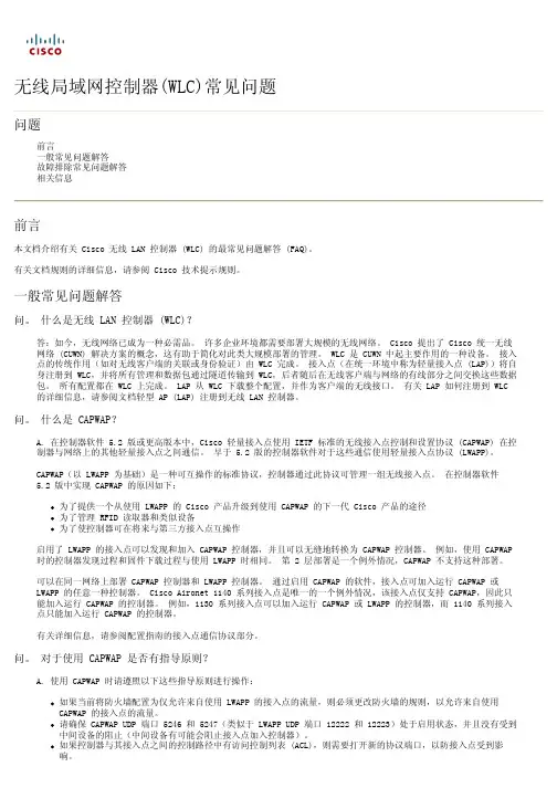
查看无线局域网控制器(WLC)错误和系统消息常见问题目录简介规则错误消息常见问题解答相关信息简介本文档介绍有关思科无线局域网(WLAN)控制器(WLC)的错误消息和系统消息的常见问题(FAQ)。
规则有关文档规则的详细信息,请参阅 Cisco 技术提示规则。
错误消息常见问题解答问:开始使用Cisco 4404 WLC将200多个接入点(AP)从Cisco IOS®软件转换为轻量AP协议(LWAPP)。
48个AP的转换已完成,WLC上收到的消息显示: [] spam_lrad.c 42121APAP。
为什么会出现此错误?A.您必须创建其他AP管理器接口才能支持超过48个AP。
否则,您将收到如下错误消息:Wed Sep 28 12:26:41 2005 [ERROR] spam_lrad.c 4212: AP cannot join becausethe maximum number of APs on interface 1 is reached.配置多个 AP 管理器接口,并配置其他 AP 管理器接口未使用的主/备份端口。
您必须创建另一个AP管理器接口以启动其他AP。
但是,请确保每个管理器的主端口和备份端口配置不会重叠。
换句话说,如果 AP 管理器 1 使用端口 1 作为主端口,端口 2 作为备份端口,则 AP 管理器 2 必须使用端口 3 作为主端口,端口 4 作为备份端口。
问:我有一台无线局域网控制器(WLC)4402,我使用1240个轻量接入点(LAP)。
我在WLC上启用了128位加密。
当我在WLC上选择128位WEP加密时,我收到一个错误消息,指出1240s不支持128位:[ERROR] spam_lrad.c 12839WEP128CISCO AP xx:xx:xx:xx:xx:xx:xx:xx:xx:xxSSID型。
为什么我会收到此错误消息?A.WLC上显示的密钥长度实际上是共享密钥中的位数,不包括初始化向量(IV)的24位。
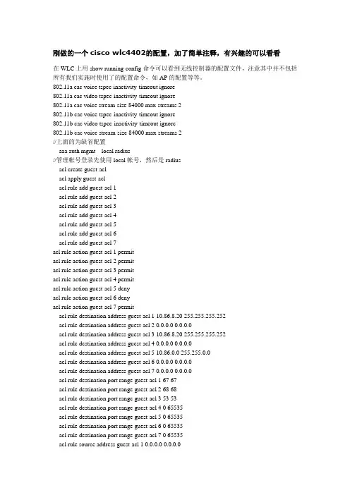
刚做的一个cisco wlc4402的配置,加了简单注释,有兴趣的可以看看在WLC上用show running-config命令可以看到无线控制器的配置文件,注意其中并不包括所有我们实施时使用了的配置命令,如AP的配置等等。
802.11a cac voice tspec-inactivity-timeout ignore802.11a cac video tspec-inactivity-timeout ignore802.11a cac voice stream-size 84000 max-streams 2802.11b cac voice tspec-inactivity-timeout ignore802.11b cac video tspec-inactivity-timeout ignore802.11b cac voice stream-size 84000 max-streams 2//上面的为缺省配置aaa auth mgmt local radius//管理帐号登录先使用local帐号,然后是radiusacl create guest-aclacl apply guest-aclacl rule add guest-acl 1acl rule add guest-acl 2acl rule add guest-acl 3acl rule add guest-acl 4acl rule add guest-acl 5acl rule add guest-acl 6acl rule add guest-acl 7acl rule action guest-acl 1 permitacl rule action guest-acl 2 permitacl rule action guest-acl 3 permitacl rule action guest-acl 4 permitacl rule action guest-acl 5 denyacl rule action guest-acl 6 denyacl rule action guest-acl 7 permitacl rule destination address guest-acl 1 10.86.8.20 255.255.255.252acl rule destination address guest-acl 2 0.0.0.0 0.0.0.0acl rule destination address guest-acl 3 10.86.8.20 255.255.255.252acl rule destination address guest-acl 4 0.0.0.0 0.0.0.0acl rule destination address guest-acl 5 10.86.0.0 255.255.0.0acl rule destination address guest-acl 6 0.0.0.0 0.0.0.0acl rule destination address guest-acl 7 0.0.0.0 0.0.0.0acl rule destination port range guest-acl 1 67 67acl rule destination port range guest-acl 2 68 68acl rule destination port range guest-acl 3 53 53acl rule destination port range guest-acl 4 0 65535acl rule destination port range guest-acl 5 0 65535acl rule destination port range guest-acl 6 0 65535acl rule destination port range guest-acl 7 0 65535acl rule source address guest-acl 1 0.0.0.0 0.0.0.0acl rule source address guest-acl 2 10.86.8.20 255.255.255.252acl rule source address guest-acl 3 0.0.0.0 0.0.0.0acl rule source address guest-acl 4 10.86.8.20 255.255.255.252acl rule source address guest-acl 5 0.0.0.0 0.0.0.0acl rule source address guest-acl 6 10.86.0.0 255.255.0.0acl rule source address guest-acl 7 0.0.0.0 0.0.0.0acl rule source port range guest-acl 1 68 68acl rule source port range guest-acl 2 67 67acl rule source port range guest-acl 3 0 65535acl rule source port range guest-acl 4 53 53acl rule source port range guest-acl 5 0 65535acl rule source port range guest-acl 6 0 65535acl rule source port range guest-acl 7 0 65535acl rule direction guest-acl 1 Inacl rule direction guest-acl 2 Outacl rule direction guest-acl 3 Inacl rule direction guest-acl 4 Outacl rule direction guest-acl 5 Inacl rule direction guest-acl 6 Outacl rule direction guest-acl 7 Anyacl rule dscp guest-acl 1 Anyacl rule dscp guest-acl 2 Anyacl rule dscp guest-acl 3 Anyacl rule dscp guest-acl 4 Anyacl rule dscp guest-acl 5 Anyacl rule dscp guest-acl 6 Anyacl rule dscp guest-acl 7 Anyacl rule protocol guest-acl 1 17acl rule protocol guest-acl 2 17acl rule protocol guest-acl 3 17acl rule protocol guest-acl 4 17acl rule protocol guest-acl 5 Anyacl rule protocol guest-acl 6 Anyacl rule protocol guest-acl 7 Anyacl apply guest-acl//我们用一个叫guest-acl的访问列表限制连接到SIH-guest的用户不能访问内网,只能上//internet。
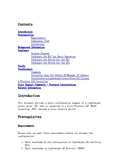
ContentsIntroductionPrerequisitesRequirementsComponents UsedConventionsBackground InformationConfigureNetwork DiagramConfigure the WLC for Basic OperationConfigure the Switch for the WLCConfigure the Switch for the APsVerifyTroubleshootCommandsController Does Not Defend AP-Manager IP AddressTroubleshoot a Lightweight Access Point Not Joininga Wireless LAN ControllerCisco Support Community - Featured ConversationsRelated InformationIntroductionThis document provides a basic configuration example of a lightweight access point (AP) that is connected to a Cisco Wireless LAN (WLAN) Controller (WLC) through a Cisco Catalyst Switch.PrerequisitesRequirementsEnsure that you meet these requirements before you attempt this configuration:∙Basic knowledge of the configuration of lightweight APs and Cisco WLCs∙Basic knowledge of Lightweight AP Protocol (LWAPP)∙Knowledge of the configuration of an external DHCP server and/or domain name server (DNS)∙Basic configuration knowledge of Cisco switchesComponents UsedThe information in this document is based on these software and hardware versions:∙Cisco Aironet 1232AG Series Lightweight AP∙Cisco 4402 Series WLC that runs firmware 5.2.178.0∙Microsoft Windows Server 2003 Enterprise DHCP serverThis configuration works with any other Cisco WLC and any lightweight AP.The information in this document was created from the devices in a specific lab environment. All of the devices used in this document started with a cleared (default) configuration. If your network is live, make sure that you understand the potential impact of any command.ConventionsRefer to the Cisco Technical Tips Conventions for more information on document conventions.Background InformationIn order for the WLC to be able to manage the LAP, the LAP should discover the controller and register with the WLC. There are different methods that an LAP uses in order to discover the WLC. For detailed information on the different methods the LAPs use to register to the WLCs, refer to Lightweight AP (LAP) Registration to a Wireless LAN Controller (WLC)This document describes the configuration steps needed to register the LAP to the WLC and for basic operation of the LWAPP wireless network.ConfigureIn order to register the LAP to the WLC and for basic operation of the LWAPP wireless network, complete these steps:1.Have a DHCP server present so that the APs can acquire a networkaddress.Note: Option 43 is used if the APs reside in a different subnet.2.Configure the WLC for basic operation.3.Configure the switch for the WLC.4.Configure the switch for the APs.5.Register the lightweight APs to the WLCs.Note: Use the Command Lookup Tool (registered customers only) in order to obtain more information on the commands used in this section.Network DiagramThis document uses this network setup:Configure the WLC for Basic OperationWhen the controller boots at factory defaults, the bootup script runs the configuration wizard, which prompts the installer for initial configuration settings. This procedure describes how to use the configuration wizard on the command-line interface (CLI) in order to enter initial configuration settings.Note: Be sure that you understand how to configure an external DHCP server and/or DNS.Complete these steps in order to configure the WLC for basicoperation:1.Connect your computer to the WLC with a DB-9 null modem serial cable.2.Open a terminal emulator session with these settings:o9600 baudo8 data bitso 1 stop bito No parityo No hardware flow control3.At the prompt, log in to the CLI.The default username is admin, and the default password is admin.4.If necessary, enter reset system in order to reboot the unit andstart the wizard.5.At the first wizard prompt, enter a system name. The system namecan include up to 32 printable ASCII characters.6.Enter an administrator user name and password. The user name andpassword can include up to 24 printable ASCII characters.7.Enter the service-port interface IP configuration protocol, eithernone or DHCP.Enter none if you do not want to use the service port or if you want to assign a static IP address to the service port.8.If you entered none in step 7 and need to enter a static IP addressfor the service port, enter the service-port interface IP address and netmask for the next two prompts.If you do not want to use the service port, enter 0.0.0.0 for the IP address and netmask.9.Enter values for these options:o Management interface IP addresso Netmasko Default router IP addresso Optional VLAN identifierYou can use a valid VLAN identifier or 0 for untagged.10.Note: When the management interface on the controller isconfigured as part of the 'native vlan' on the switchport to which it connects, the controller should NOT tag the frames. Therefore, you must set the VLAN to be zero (on the controller).11.Enter the Network Interface (Distribution System) Physical Portnumber.For the WLC, the possible ports are 1 through 4 for a front-panel gigabit Ethernet port.12.Enter the IP address of the default DHCP server that supplies IPaddresses to clients, the management interface, and theservice-port interface, if you use one.13.Enter the LWAPP Transport Mode, either LAYER2 or LAYER3.Note: If you configure the WLC 4402 via Wizard and select AP transport Mode LAYER2, the Wizard does not ask the details of AP Manager.14.Enter the Virtual Gateway IP Address.This address can be any fictitious, unassigned IP address, such as1.1.1.1, for the Layer 3 Security and Mobility managers to use.Note: Usually the Virtual Gateway IP Address that is used is a private address.15.Enter the Cisco WLAN Solution Mobility Group/RF Group name.16.Enter the WLAN 1 service set identifier (SSID) or network name.This identifier is the default SSID that lightweight APs use in order to associate to a WLC.17.Allow or disallow Static IP Addresses for clients.Enter yes in order to allow clients to supply their own IP addresses.Enter no in order to require clients to request an IP address froma DHCP server.18.If you need to configure a RADIUS server on the WLC, enter yes andenter this information:o RADIUS server IP addresso The communication porto The shared secretIf you do not need to configure a RADIUS server or you want to configure the server later, enter no.19.Enter a country code for the unit.Enter help in order to see a list of the supported countries.20.Enable and disable support for IEEE 802.11b, IEEE 802.11a, and IEEE802.11g.21.Enable or disable radio resource management (RRM) (auto RF).WLC 4402—Configuration WizardWelcome to the Cisco Wizard Configuration ToolUse the '-' character to backupSystem Name [Cisco_43:eb:22]: c4402Enter Administrative User Name (24 characters max): adminEnter Administrative Password (24 characters max): *****Service Interface IP Address Configuration [none][DHCP]: noneEnable Link Aggregation (LAG) [yes][NO]: No Management Interface IP Address:192.168.60.2Management Interface Netmask:255.255.255.0Management Interface Default Router: 192.168.60.1Management Interface VLAN Identifier (0 = untagged): 60Management Interface Port Num [1 to 2]: 1 Management Interface DHCP Server IP Address: 192.168.60.25AP Transport Mode [layer2][LAYER3]: LAYER3 AP Manager Interface IP Address:192.168.60.3AP-Manager is on Management subnet, using same valuesAP Manager Interface DHCP Server(192.168.50.3): 192.168.60.25Virtual Gateway IP Address: 1.1.1.1 Mobility/RF Group Name: RFgroupname Network Name (SSID): SSIDAllow Static IP Addresses [YES][no]: yes Configure a RADIUS Server now? [YES][no]: no Enter Country Code (enter 'help' for a list of countries) [US]: USEnable 802.11b Network [YES][no]: yes Enable 802.11a Network [YES][no]: yes Enable 802.11g Network [YES][no]: yes Enable Auto-RF [YES][no]: yesNote: The management interface on the WLC is the only consistently pingable interface from outside of the WLC. So it is an expected behavior if you are not able to ping the AP manager interface from outside of the WLC.Note: You must configure the AP manager interface in order for the APs to associate with the WLC.Configure the Switch for the WLCThis example uses a Catalyst 3750 switch that uses only one port. The example tags the AP-manager and management interfaces and places these interfaces on VLAN 60. The switch port is configured as an IEEE 802.1Q trunk and only the appropriate VLANs, which are VLANs 2 through 4 and 60 in this case, are allowed on the trunk. The management and AP-manager VLAN (VLAN 60) is tagged and is not configured as the native VLAN of the trunk. So when the example configures those interfaces on the WLC, the interfaces are assigned a VLAN identifier.This is an example 802.1Q switch port configuration:interface GigabitEthernet1/0/1description Trunk Port to Cisco WLCswitchport trunk encapsulation dot1qswitchport trunk allowed vlan 2-4,60switchport mode trunkno shutdownNote: When you connect the WLC gigabit port, make sure it is connected to the switch gigabit port only. If you connect the WLC gigabit Ethernet to the Switch FastEthernet port then it will not work.Notice that this configuration example configures the neighbor switch port in a way that only allows relevant VLANs on the 802.1Q trunk. All other VLANs are pruned. This type of configuration is not necessary, but it is a deployment best practice. When you prune irrelevant VLANs, the WLC only processes relevant frames, which optimizes performance.Configure the Switch for the APsThis is an example VLAN interface configuration from the Catalyst 3750: interface VLAN5description AP VLANip address 10.5.5.1 255.255.255.0While the Cisco WLCs always connect to 802.1Q trunks, Cisco lightweight APs do not understand VLAN tagging and should only be connected to the access ports of the neighbor switch.This is an example switch port configuration from the Catalyst 3750:interface GigabitEthernet1/0/22description Access Port Connection to Cisco Lightweight APswitchport access vlan 5switchport mode accessno shutdownThe infrastructure is now ready for connection to the APs. The LAPs use the different WLC discovery methods and select a WLC to join. The LAP then registers with the controller.Here is a link to a video on the Cisco Support Community that explainsthe initial configuration of Wireless LAN Controller using the CLI and GUI: Initial configuration of Wireless LAN Controller using the CLI andGUIVerifyUse this section in order to confirm that your configuration works properly.After the LAPs register with the controller, you can view them under Wireless at the top of the user interface of the controller:On the CLI, you can use the show ap summary command in order to verify that the LAPs registered with the WLC:(Cisco Controller) >show ap summaryNumber of APs (1)Global AP User Name.............................. Not Configured Global AP Dot1x User Name........................ Not ConfiguredAP Name Slots AP Model Ethernet MAC Location Port Country Priority------------------ ----- ------------------- --------------------------------- ---- ------- ------AP001b.d4e3.a81b 2 AIR-LAP1232AG-A-K9 00:1b:d4:e3:a8:1b default location 2 IN 1On the WLC CLI, you can also use the show client summary command in order to see the clients that are registered with the WLC:(Cisco Controller) >show client summaryNumber of Clients (1)MAC Address AP Name Status WLAN Auth Protocol Port----------------- ------------- ------------- ---- ---- -------- ----00:40:96:a1:45:42 ap:64:a3:a0 Associated 4 Yes 802.11a 1(Cisco Controller) >Here is a video demonstration that explains how to perform the initial configuration of a Wireless LAN Controller using the GUI and CLI: InitialConfiguration of Wireless Lan Controller using CLI and GUITroubleshootUse this section in order to troubleshoot your configuration. CommandsUse these commands in order to troubleshoot your configuration.Note: Refer to Important Information on Debug Commands before you use debug commands.This debug lwapp events enable WLC command output shows that the lightweight AP gets registered to the WLC:(Cisco Controller) >debug lwapp events enableTue Apr 11 13:38:47 2006: Received LWAPP DISCOVERY REQUEST from AP00:0b:85:64:a3:a0 to ff:ff:ff:ff:ff:ff on port '1'Tue Apr 11 13:38:47 2006: Successful transmission of LWAPPDiscovery-Responseto AP 00:0b:85:64:a3:a0 on Port 1Tue Apr 11 13:38:58 2006: Received LWAPP JOIN REQUEST from AP00:0b:85:64:a3:a0 to 00:0b:85:33:a8:a0 on port '1'Tue Apr 11 13:38:58 2006: LWAPP Join-Request MTU path from AP00:0b:85:64:a3:a0is 1500, remote debug mode is 0Tue Apr 11 13:38:58 2006: Successfully added NPU Entry for AP00:0b:85:64:a3:a0 (index 48) Switch IP: 192.168.60.2, Switch Port: 12223,intIfNum 1, vlanId 60 AP IP: 10.5.5.10, AP Port: 19002, next hop MAC: 00:0b:85:64:a3:a0Tue Apr 11 13:38:58 2006: Successfully transmission of LWAPP Join-Reply to AP00:0b:85:64:a3:a0Tue Apr 11 13:38:58 2006: Register LWAPP event for AP00:0b:85:64:a3:a0 slot 0Tue Apr 11 13:38:58 2006: Register LWAPP event for AP 00:0b:85:64:a3:a0 slot 1Tue Apr 11 13:39:00 2006: Received LWAPP CONFIGURE REQUEST from AP00:0b:85:64:a3:a0 to 00:0b:85:33:a8:a0Tue Apr 11 13:39:00 2006: Updating IP info for AP 00:0b:85:64:a3:a0 -- static 0, 10.5.5.10/255.255.255.0, gtw 192.168.60.1Tue Apr 11 13:39:00 2006: Updating IP 10.5.5.10 ===> 10.5.5.10 for AP 00:0b:85:64:a3:a0Tue Apr 11 13:39:00 2006: spamVerifyRegDomain RegDomain set for slot 0 code 0regstring -A regDfromCb -ATue Apr 11 13:39:00 2006: spamVerifyRegDomain RegDomain set for slot 1 code 0regstring -A regDfromCb -ATue Apr 11 13:39:00 2006: spamEncodeDomainSecretPayload:Send domain secretMobilityGroup<6f,39,74,cd,7e,a4,81,86,ca,32,8c,06,d3,ff,ec,6d,95,10,99,dd>to AP 00:0b:85:64:a3:a0Tue Apr 11 13:39:00 2006: Successfully transmission of LWAPPConfig-Message to AP 00:0b:85:64:a3:a0Tue Apr 11 13:39:00 2006: Running spamEncodeCreateVapPayload for SSID 'SSID'Tue Apr 11 13:39:00 2006: AP 00:0b:85:64:a3:a0 associated. Last AP failure wasdue to Configuration changes, reason: operator changed 11g mode Tue Apr 11 13:39:00 2006: Received LWAPP CHANGE_STATE_EVENT from AP 00:0b:85:64:a3:a0Tue Apr 11 13:39:00 2006: Successfully transmission of LWAPPChange-State-EventResponse to AP 00:0b:85:64:a3:a0Tue Apr 11 13:39:00 2006: Received LWAPP Up event for AP 00:0b:85:64:a3:a0 slot 0!Tue Apr 11 13:39:00 2006: Received LWAPP CONFIGURE COMMAND RES from AP 00:0b:85:64:a3:a0Tue Apr 11 13:39:00 2006: Received LWAPP CHANGE_STATE_EVENT from AP 00:0b:85:64:a3:a0Tue Apr 11 13:39:00 2006: Successfully transmission of LWAPPChange-State-EventResponse to AP 00:0b:85:64:a3:a0Tue Apr 11 13:39:00 2006: Received LWAPP Up event for AP00:0b:85:64:a3:a0 slot 1!This output shows these useful WLC debug commands:∙debug pem state enable—Configures the access policy manager debug options∙debug pem events enable∙debug dhcp message enable—Shows the debug of DHCP messages that are exchanged to and from the DHCP server∙debug dhcp packet enable—Shows the debug of DHCP packet details that are sent to and from the DHCP serverTue Apr 11 14:30:49 2006: Applied policy for mobile 00:40:96:a1:45:42 Tue Apr 11 14:30:49 2006: STA [00:40:96:a1:45:42, 192.168.1.41] Replacing FastPath rule type = Airespace AP Client on AP 00:0B:85:64:A3:A0, slot 0InHandle = 0x00000000, OutHandle = 0x00000000 ACL Id = 255, Jumbo Frames= NO, interface = 1 802.1P = 0, DSCP = 0, TTue Apr 11 14:30:49 2006: Successfully plumbed mobile rule for mobile 00:40:96:a1:45:42 (ACL ID 255)Tue Apr 11 14:30:49 2006: Plumbed mobile LWAPP rule on AP00:0b:85:64:a3:a0for mobile 00:40:96:a1:45:42Tue Apr 11 14:30:53 2006: DHCP proxy received packet, src: 0.0.0.0, len = 320Tue Apr 11 14:30:53 2006: dhcpProxy: Received packet: Client00:40:96:a1:45:42DHCP Op: BOOTREQUEST(1), IP len: 320, switchport: 1, encap: 0xec03 Tue Apr 11 14:30:53 2006: dhcpProxy(): dhcp request, client:00:40:96:a1:45:42: dhcp op: 1, port: 1, encap 0xec03, old mscbport number: 1Tue Apr 11 14:30:53 2006: dhcp option len, including the magic cookie = 84Tue Apr 11 14:30:53 2006: dhcp option: received DHCP REQUEST msgTue Apr 11 14:30:53 2006: dhcp option: skipping option 61, len 7Tue Apr 11 14:30:53 2006: dhcp option: requested ip = 192.168.1.41 Tue Apr 11 14:30:53 2006: dhcp option: skipping option 12, len 15Tue Apr 11 14:30:53 2006: dhcp option: skipping option 81, len 19Tue Apr 11 14:30:53 2006: dhcp option: vendor class id = MSFT 5.0 (len 8)Tue Apr 11 14:30:53 2006: dhcp option: skipping option 55, len 11Tue Apr 11 14:30:53 2006: dhcpParseOptions: options end, len 84, actual 84Tue Apr 11 14:30:53 2006: mscb->dhcpServer: 192.168.60.2,mscb->dhcpNetmask:255.255.255.0,mscb->dhcpGateway: 192.168.60.1, mscb->dhcpRelay:192.168.60.2 VLAN: 60Tue Apr 11 14:30:53 2006: Local Address: 192.168.60.2, DHCP Server: 192.168.60.2, Gateway Addr: 192.168.60.2, VLAN: 60, port: 1Tue Apr 11 14:30:53 2006: DHCP Message Type received: DHCP REQUEST msg Tue Apr 11 14:30:53 2006: op: BOOTREQUEST, htype: Ethernet, hlen: 6, hops: 1Tue Apr 11 14:30:53 2006: xid: 3371152053, secs: 0, flags: 0Tue Apr 11 14:30:53 2006: chaddr: 00:40:96:a1:45:42Tue Apr 11 14:30:53 2006: ciaddr: 0.0.0.0, yiaddr: 0.0.0.0Tue Apr 11 14:30:53 2006: siaddr: 0.0.0.0, giaddr: 192.168.60.2Tue Apr 11 14:30:53 2006: Forwarding DHCP packet locally (348 octets) from 192.168.60.2 to 192.168.60.2Tue Apr 11 14:30:53 2006: Received 348 byte dhcp packet from 0x0201a8c0 192.168.60.2:68Tue Apr 11 14:30:53 2006: DHCP packet: 192.168.60.2 -> 192.168.60.2 using scope "InternalScope"Tue Apr 11 14:30:53 2006: received REQUESTTue Apr 11 14:30:53 2006: Checking node 192.168.1.41 Allocated 1144765719,Expires 1144852119 (now: 1144765853)Tue Apr 11 14:30:53 2006: adding option 0x35Tue Apr 11 14:30:53 2006: adding option 0x36Tue Apr 11 14:30:53 2006: adding option 0x33Tue Apr 11 14:30:53 2006: adding option 0x03Tue Apr 11 14:30:53 2006: adding option 0x01Tue Apr 11 14:30:53 2006: dhcpd: Sending DHCP packet(giaddr:192.168.60.2)to192.168.60.2:67 from 192.168.60.2:1067Tue Apr 11 14:30:53 2006: sendto (548 bytes) returned 548Tue Apr 11 14:30:53 2006: DHCP proxy received packet, src: 192.168.60.2, len = 548Tue Apr 11 14:30:53 2006: dhcpProxy: Received packet: Client00:40:96:a1:45:42DHCP Op: BOOTREPLY(2), IP len: 548, switchport: 0, encap: 0x0Tue Apr 11 14:30:53 2006: dhcp option len, including the magic cookie = 312Tue Apr 11 14:30:53 2006: dhcp option: received DHCP ACK msgTue Apr 11 14:30:53 2006: dhcp option: server id = 192.168.60.2Tue Apr 11 14:30:53 2006: dhcp option: lease time (seconds) = 86400 Tue Apr 11 14:30:53 2006: dhcp option: gateway = 192.168.60.1Tue Apr 11 14:30:53 2006: dhcp option: netmask = 255.255.255.0Tue Apr 11 14:30:53 2006: dhcpParseOptions: options end, len 312, actual 64Tue Apr 11 14:30:53 2006: DHCP Reply to AP client: 00:40:96:a1:45:42, frame len 412, switchport 1Tue Apr 11 14:30:53 2006: DHCP Message Type received: DHCP ACK msgTue Apr 11 14:30:53 2006: op: BOOTREPLY, htype: Ethernet, hlen: 6, hops: 0Tue Apr 11 14:30:53 2006: xid: 3371152053, secs: 0, flags: 0Tue Apr 11 14:30:53 2006: chaddr: 00:40:96:a1:45:42Tue Apr 11 14:30:53 2006: ciaddr: 0.0.0.0, yiaddr: 192.168.1.41Tue Apr 11 14:30:53 2006: siaddr: 0.0.0.0, giaddr: 0.0.0.0Tue Apr 11 14:30:53 2006: server id: 1.1.1.1 rcvd server id:192.168.60.2You can use these additional debug commands in order to troubleshoot your configuration:∙debug lwapp errors enable—Shows output of the debug of LWAPP errors ∙debug pm pki enable—Shows the debug of certificate messages that are passed between the AP and the WLCController Does Not Defend AP-Manager IP AddressThis issues is a result of bug CSCsg75863. If the user accidently injects a device on the subnet that uses the AP-manager IP address of the controller, the Address Resolution Protocol (ARP) cache on the default gateway router is refreshed with the wrong MAC address. When this occurs, the APs can no longer reach the controller and drop into their discovery phase to look for a controller. The APs send discovery requests, and the controller responds with discovery replies, but the JOIN requests never reach the AP-manager interface of the controller because of the bad ARP entry on the gateway router. After the default 4 hour ARP refresh interval, the APs join the controller if the device is removed.A workaround for this issue is to configure the static ARP entries on the gateway router of the controller for these IP addresses:∙Management IP address—Customers gain access to the graphical user interface (GUI) from another subnet, and the controller receives the AP discovery requests.∙AP-Manager IP address—APs join the controller from another subnet.∙Every Dynamic interface IP address—Packets from other subnets reach the dynamic interface of the controller.DHCP packets transmit from the interface of the wireless client. Telnet or SSH to the gateway address of the controller, and use the arp <ip address> <hhhh.hhhh.hhhh> command in order to add the ARP entries. Use the ping command on the default router of the controller to the different addresses in order to refresh the ARP cache on the router. In order to discover the MAC addresses, use this command: show arp | include <ip address>.Troubleshoot a Lightweight Access Point Not Joining a Wireless LAN ControllerRefre to Troubleshoot a Lightweight Access Point Not Joining a Wireless LAN Controller for information on some of the issues why a Lightweight Access Point (LAP) fails to join a WLC and how to troubleshoot the issues.Cisco Support Community - Featured ConversationsCisco Support Community is a forum for you to ask and answer questions, share suggestions, and collaborate with your peers. Below are just some of the most recent and relevant conversations happening right now.。

无线配置手册WLC配置手册基本配置1.初始设置连接到WLC的console口,启动超级终端或其它终端软件,把com口属性设置还原为默认值(如下图),点确定应用配置回车进入命令行管理界面选择5,清除原有设置,并进行初始设置Welcome to the Cisco Wizard Configuration ToolUse the '-' character to backupSystem Name [Cisco_40:4a:03]: C1-CONTROLLER-01Enter Administrative User Name (24 characters max): adminEnter Administrative Password (24 characters max):minshenma Service Interface IP Address Configuration [none][DHCP]: 192.168.1.1 Management Interface IP Address: 10.1.128.101Management Interface Netmask: 255.255.255.0Management Interface Default Router: 10.1.128.254Management Interface VLAN Identifier (0 = untagged): 128 Management Interface DHCP Server IP Address:10.1.32.1AP Manager Interface IP Address: 10.1.128.103AP Manager Interface DHCP Server : 10.1.32.1AP Transport Mode [Layer2] [Layer3]: Layer3Virtual Gateway IP Address: 10.254.100.101Mobility/RF Group Name: wukuangNetwork Name (SSID): managementAllow Static IP Addresses [YES][no]: yesConfigure a RADIUS Server now? [YES][no]: noEnable 802.11b Network [YES][no]: yesEnable 802.11a Network [YES][no]: yesEnable 802.11g Network [YES][no]: yesEnable Auto-RF [YES][no]: yesConfiguration saved!Resetting system with new configuration...至此,WLC初始设置完成。
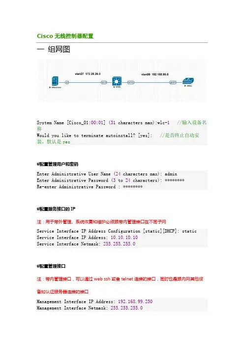
Cisco无线控制器配置一组网图System Name [Cisco_01:00:01] (31 characters max):wlc-1//输入设备名称Would you like to terminate autoinstall? [yes]: //是否终止自动安装,默认是yes#配置管理用户和密码Enter Administrative User Name (24 characters max): adminEnter Administrative Password (3 to 24 characters): ********Re-enter Administrative Password : ********#配置服务接口的IP注:用于带外管理、系统恢复和维护必须跟带内管理接口在不同子网Service Interface IP Address Configuration [static][DHCP]: static Service Interface IP Address: 10.10.10.10Service Interface Netmask: 255.255.255.0#配置管理接口注:带内管理接口,可以通过web ssh或者telnet连接的接口,同时也是跟内网其他设备如认证服务器连接的接口Management Interface IP Address: 192.168.99.250Management Interface Netmask: 255.255.255.0Management Interface Default Router: 192.168.99.254Management Interface VLAN Identifier (0 = untagged): 99Management Interface Port Num [1 to 1]: 1Management Interface DHCP Server IP Address: 192.168.99.254#设置虚拟网关注:为三层漫游而设置的虚拟接口,在同一个mobility group里的WLC都必须配置相同的虚拟接口Virtual Gateway IP Address: 1.1.1.1#配置Mobility/RF Group名称注:用于用户在不同控制器下的AP间的三层漫游,所以不同控制器的该组必须相同Mobility/RF Group Name: test#配置默认的SSID注:LAP加入控制器时将使用它,LAP加入后WLC会把其他的SSID提供给LAP Network Name (SSID): test#dhcp桥接注:Bridging Mode 将会把DHCP 请求透传出去,不做处理;一般都使用WLC本身中继代理功能,默认NO。
思科4400系列WLC快速使用指南目录关于本手册 (3)安全声明 (3)控制器介绍 (3)控制器状态灯 (4)WLC开箱与操作 (5)WLC组件 (5)需要的工具和信息 (5)初始化系统配置信息 (6)选择位置 (6)连接到WLC的Console口 (7)运行启动脚本和系统自检 (8)使用启动向导 (11)登录WLC (12)核实接口配置和状态 (13)连接网络(汇聚) (14)Model 4402 Controllers (14)Model 4404 Controllers (14)连接WLC服务端口(可选) (14)链接AP (14)安装电源模块 (14)准备工具 (15)安装VPN模块 (16)准备工具 (16)关于本手册本手册用来帮助您了解CIsoc4400系列WLC的安装和最小化配置。
主要包括以下WLC 型号: 4402-25, 4402-50, 4404-25, 4404-50, and 4404-100.安全声明使用前注意一下事项:•确保环境温度在32 to 104° F (0 to 40° C)•确保充足的供电.•确保电源接地.控制器介绍Cisco 4400系列控制器(WLC)为无线网络部署提供最高级别的性能和扩展性,并且保护网络中现有的投资。
作为无线网络的核心部分,控制器可以提供安全、干扰检测、射频管理、服务质量保障、无线漫游等功能,并可以和其他控制器、Cisco无线控制系统(WCS)、AP协同工作,以提供一个完善的无线网络方案。
为了更好地使用本文,我们假定您已经完成了无线网络的结构设计。
射频资源管理功能自动检测并配置网络中出现的AP。
4400系列WlCT包括两款型号4402和 4404。
4402有两个分布式千兆以太网接口,每个接口可以管理多达48个AP,尽管如此,Cisco建议为了保证带宽每个接口管理的AP数量不要超过25个。
4402-25和4402-50分别支持25和50个AP注册到WLC中。
带IOS DHCP服务器的WLC自动安装功能配置示例目录简介先决条件要求使用的组件规则WLC自动安装功能配置 DHCP 服务器自动安装实施输出示例:在WLC的相关信息简介本文提供信息关于怎样自动安装功能在无线局域网控制器(WLC)工作该用途Cisco IOS路由器作为DHCP服务器。
先决条件要求Cisco 建议您了解以下主题:配置基本操作的WLCq有关轻量接入点协议 (LWAPP) 的基本知识q使用的组件本文档中的信息基于下列硬件和软件版本:运行版本6.0的4400系列WLCq运行软件版本12.4(11)的2800系列路由器q比32 MB能上传文件极大的任何TFTP serverq规则有关文档规则的详细信息,请参阅 Cisco 技术提示规则。
WLC自动安装功能自动安装功能是实现的开始与WLC软件版本5.0及以上版本。
当您启动没有一配置的控制器时,自动安装功能能下载从TFTP server的一个配置文件自动地然后装载配置到控制器。
创建从已经在网络的控制器的一个配置文件(或通过WCS过滤器)并且放置该配置文件在TFTP server。
配置DHCP服务器这样它povides IP地址、TFTP server、主机名等等,对WLC。
自动安装功能能自动地得到新的控制器的配置文件。
当控制器启动时,自动安装进程从此提示符开始并且坚持在30秒:Would you like to terminate autoinstall?[yes] :如果按回车或类型‘是的,自动安装然后结束。
或者,在30秒中止超时到期后,自动安装开始DHCP客户端。
如果输入是在提示符,您能在此30秒超时以后中止自动安装任务。
然而,如果TFTP任务锁定闪存并且是在下载和安装有效配置文件过程中,自动安装不可能中止。
自动安装使用这些接口:4400 系列控制器eth0 —服务端口(无标记)dtl0 —千兆端口1通过NPU (无标记) q2100 系列控制器dtl0 —快速以太网端口1 (无标记)q为了使工作自动安装的功能,应该配置DHCP服务器提供这些选项之一给WLC,与IP地址和TFTP server信息一起。
cisco⽆线控制配置说明ContentsIntroductionPrerequisitesRequirementsComponents UsedConventionsBackground InformationConfigureNetwork DiagramConfigure the WLC for Basic OperationConfigure the Switch for the WLCConfigure the Switch for the APsVerifyTroubleshootCommandsController Does Not Defend AP-Manager IP AddressTroubleshoot a Lightweight Access Point Not Joininga Wireless LAN ControllerCisco Support Community - Featured ConversationsRelated InformationIntroductionThis document provides a basic configuration example of a lightweight access point (AP) that is connected to a Cisco Wireless LAN (WLAN) Controller (WLC) through a Cisco Catalyst Switch.PrerequisitesRequirementsEnsure that you meet these requirements before you attempt this configuration:Basic knowledge of the configuration of lightweight APs and Cisco WLCsBasic knowledge of Lightweight AP Protocol (LWAPP)Knowledge of the configuration of an external DHCP server and/or domain name server (DNS)Basic configuration knowledge of Cisco switchesComponents UsedThe information in this document is based on these software and hardware versions:Cisco Aironet 1232AG Series Lightweight APCisco 4402 Series WLC that runs firmware 5.2.178.0Microsoft Windows Server 2003 Enterprise DHCP serverThis configuration works with any other Cisco WLC and any lightweight AP.The information in this document was created from the devices in a specific lab environment. All of the devices used in this document started with a cleared (default) configuration. If your network is live, make sure that you understand the potential impact of any command.ConventionsRefer to the Cisco Technical Tips Conventions for more information on document conventions.Background InformationIn order for the WLC to be able to manage the LAP, the LAP should discover the controller and register with the WLC. There are different methods that an LAP uses in order to discover the WLC. For detailed information on the different methods the LAPs use to register to the WLCs, refer to Lightweight AP (LAP) Registration to a Wireless LAN Controller (WLC)This document describes the configuration steps needed to register the LAP to the WLC and for basic operation of the LWAPP wireless network.ConfigureIn order to register the LAP to the WLC and for basic operation of the LWAPP wireless network, complete these steps:1.Have a DHCP server present so that the APs can acquire a networkaddress.Note: Option 43 is used if the APs reside in a different subnet.2.Configure the WLC for basic operation.3.Configure the switch for the WLC.4.Configure the switch for the APs.5.Register the lightweight APs to the WLCs.Note: Use the Command Lookup Tool (registered customers only) in order to obtain more information on the commands used in this section.Network DiagramThis document uses this network setup:Configure the WLC for Basic OperationWhen the controller boots at factory defaults, the bootup script runs the configuration wizard, which prompts the installer for initial configuration settings. This procedure describes how to use the configuration wizard on the command-line interface (CLI) in order to enter initial configuration settings.Note: Be sure that you understand how to configure an external DHCP server and/or DNS.Complete these steps in order to configure the WLC for basicoperation:1.Connect your computer to the WLC with a DB-9 null modem serial cable.2.Open a terminal emulator session with these settings:o9600 baudo8 data bitso 1 stop bito No parityo No hardware flow control3.At the prompt, log in to the CLI.The default username is admin, and the default password is admin.4.If necessary, enter reset system in order to reboot the unit andstart the wizard.5.At the first wizard prompt, enter a system name. The system namecan include up to 32 printable ASCII characters.6.Enter an administrator user name and password. The user name andpassword can include up to 24 printable ASCII characters.7.Enter the service-port interface IP configuration protocol, eithernone or DHCP.Enter none if you do not want to use the service port or if you want to assign a static IP address to the service port. 8.If you entered none in step 7 and need to enter a static IP addressfor the service port, enter the service-port interface IP address and netmask for the next two prompts.If you do not want to use the service port, enter 0.0.0.0 for the IP address and netmask.9.Enter values for these options:o Management interface IP addresso Netmasko Default router IP addresso Optional VLAN identifierYou can use a valid VLAN identifier or 0 for untagged.10.Note: When the management interface on the controller isconfigured as part of the 'native vlan' on the switchport to which it connects, the controller should NOT tag the frames. Therefore, you must set the VLAN to be zero (on the controller).11.Enter the Network Interface (Distribution System) Physical Portnumber.For the WLC, the possible ports are 1 through 4 for a front-panel gigabit Ethernet port.12.Enter the IP address of the default DHCP server that supplies IPaddresses to clients, the management interface, and theservice-port interface, if you use one.13.Enter the LWAPP Transport Mode, either LAYER2 or LAYER3.Note: If you configure the WLC 4402 via Wizard and select AP transport Mode LAYER2, the Wizard does not ask the details of AP Manager.14.Enter the Virtual Gateway IP Address.This address can be any fictitious, unassigned IP address, such as1.1.1.1, for the Layer 3 Security and Mobility managers to use.Note: Usually the Virtual Gateway IP Address that is used is a private address.15.Enter the Cisco WLAN Solution Mobility Group/RF Group name.16.Enter the WLAN 1 service set identifier (SSID) or network name.This identifier is the default SSID that lightweight APs use in order to associate to a WLC.17.Allow or disallow Static IP Addresses for clients.Enter yes in order to allow clients to supply their own IP addresses.Enter no in order to require clients to request an IP address froma DHCP server.18.If you need to configure a RADIUS server on the WLC, enter yes andenter this information:o RADIUS server IP addresso The communication porto The shared secretIf you do not need to configure a RADIUS server or you want to configure the server later, enter no.19.Enter a country code for the unit.Enter help in order to see a list of the supported countries.20.Enable and disable support for IEEE 802.11b, IEEE 802.11a, and IEEE802.11g.21.Enable or disable radio resource management (RRM) (auto RF).WLC 4402—Configuration WizardWelcome to the Cisco Wizard Configuration ToolUse the '-' character to backupSystem Name [Cisco_43:eb:22]: c4402Enter Administrative User Name (24 characters max): adminEnter Administrative Password (24 characters max): *****Service Interface IP Address Configuration [none][DHCP]: noneEnable Link Aggregation (LAG) [yes][NO]: No Management Interface IP Address:192.168.60.2Management Interface Netmask:255.255.255.0Management Interface Default Router: 192.168.60.1Management Interface VLAN Identifier (0 = untagged): 60Management Interface Port Num [1 to 2]: 1 Management Interface DHCP Server IP Address: 192.168.60.25AP Transport Mode [layer2][LAYER3]: LAYER3 AP Manager Interface IP Address:192.168.60.3AP-Manager is on Management subnet, using same valuesAP Manager Interface DHCP Server(192.168.50.3): 192.168.60.25Virtual Gateway IP Address: 1.1.1.1 Mobility/RF Group Name: RFgroupname Network Name (SSID): SSIDAllow Static IP Addresses [YES][no]: yes Configure a RADIUS Server now? [YES][no]: no Enter Country Code (enter 'help' for a list of countries) [US]: USEnable 802.11b Network [YES][no]: yes Enable 802.11a Network [YES][no]: yes Enable 802.11g Network [YES][no]: yes Enable Auto-RF [YES][no]: yesNote: The management interface on the WLC is the only consistently pingable interface from outside of the WLC. So it is an expected behavior if you are not able to ping the AP manager interface from outside of the WLC.Note: You must configure the AP manager interface in order for the APs to associate with the WLC.Configure the Switch for the WLCThis example uses a Catalyst 3750 switch that uses only one port. The example tags the AP-manager and management interfaces and places these interfaces on VLAN 60. The switch port is configured as an IEEE 802.1Q trunk and only the appropriate VLANs, which are VLANs 2 through 4 and 60 in this case, are allowed on the trunk. The management and AP-manager VLAN (VLAN 60) is tagged and is not configured as the native VLAN of the trunk. So when the example configures those interfaces on the WLC, the interfaces are assigned a VLAN identifier.This is an example 802.1Q switch port configuration:interface GigabitEthernet1/0/1description Trunk Port to Cisco WLCswitchport trunk encapsulation dot1qswitchport trunk allowed vlan 2-4,60switchport mode trunkno shutdownNote: When you connect the WLC gigabit port, make sure it is connected to the switch gigabit port only. If you connect the WLC gigabit Ethernet to the Switch FastEthernet port then it will not work.Notice that this configuration example configures the neighbor switch port in a way that only allows relevant VLANs on the 802.1Q trunk. All other VLANs are pruned. This type of configuration is not necessary, but it is a deployment best practice. When you prune irrelevant VLANs, the WLC only processes relevant frames, which optimizes performance.Configure the Switch for the APsThis is an example VLAN interface configuration from the Catalyst 3750: interface VLAN5description AP VLANip address 10.5.5.1 255.255.255.0While the Cisco WLCs always connect to 802.1Q trunks, Cisco lightweight APs do not understand VLAN tagging and should only be connected to the access ports of the neighbor switch.This is an example switch port configuration from the Catalyst 3750:interface GigabitEthernet1/0/22description Access Port Connection to Cisco Lightweight APswitchport access vlan 5switchport mode accessno shutdownThe infrastructure is now ready for connection to the APs. The LAPs use the different WLC discovery methods and select a WLC to join. The LAP then registers with the controller.Here is a link to a video on the Cisco Support Community that explainsthe initial configuration of Wireless LAN Controller using the CLI and GUI: Initial configuration of Wireless LAN Controller using the CLI andGUIVerifyUse this section in order to confirm that your configuration works properly.After the LAPs register with the controller, you can view them under Wireless at the top of the user interface of the controller:On the CLI, you can use the show ap summary command in order to verify that the LAPs registered with the WLC: (Cisco Controller) >show ap summaryNumber of APs (1)Global AP User Name.............................. Not Configured Global AP Dot1x User Name........................ Not ConfiguredAP Name Slots AP Model Ethernet MAC Location Port Country Priority------------------ ----- ------------------- --------------------------------- ---- ------- ------AP001b.d4e3.a81b 2 AIR-LAP1232AG-A-K9 00:1b:d4:e3:a8:1b default location 2 IN 1On the WLC CLI, you can also use the show client summary command in order to see the clients that are registered with the WLC:(Cisco Controller) >show client summaryNumber of Clients (1)MAC Address AP Name Status WLAN Auth Protocol Port----------------- ------------- ------------- ---- ---- -------- ----00:40:96:a1:45:42 ap:64:a3:a0 Associated 4 Yes 802.11a 1(Cisco Controller) >Here is a video demonstration that explains how to perform the initial configuration of a Wireless LAN Controller using the GUI and CLI: InitialConfiguration of Wireless Lan Controller using CLI and GUITroubleshootUse this section in order to troubleshoot your configuration. CommandsUse these commands in order to troubleshoot your configuration.Note: Refer to Important Information on Debug Commands before you use debug commands.This debug lwapp events enable WLC command output shows that the lightweight AP gets registered to the WLC: (Cisco Controller) >debug lwapp events enableTue Apr 11 13:38:47 2006: Received LWAPP DISCOVERY REQUEST from AP00:0b:85:64:a3:a0 to ff:ff:ff:ff:ff:ff on port '1'Tue Apr 11 13:38:47 2006: Successful transmission of LWAPPDiscovery-Responseto AP 00:0b:85:64:a3:a0 on Port 1Tue Apr 11 13:38:58 2006: Received LWAPP JOIN REQUEST from AP00:0b:85:64:a3:a0 to 00:0b:85:33:a8:a0 on port '1'Tue Apr 11 13:38:58 2006: LWAPP Join-Request MTU path from AP00:0b:85:64:a3:a0is 1500, remote debug mode is 0Tue Apr 11 13:38:58 2006: Successfully added NPU Entry for AP00:0b:85:64:a3:a0 (index 48) Switch IP: 192.168.60.2, Switch Port: 12223,intIfNum 1, vlanId 60 AP IP: 10.5.5.10, AP Port: 19002, next hop MAC: 00:0b:85:64:a3:a0Tue Apr 11 13:38:58 2006: Successfully transmission of LWAPP Join-Reply to AP00:0b:85:64:a3:a0Tue Apr 11 13:38:58 2006: Register LWAPP event for AP00:0b:85:64:a3:a0 slot 0Tue Apr 11 13:38:58 2006: Register LWAPP event for AP 00:0b:85:64:a3:a0 slot 1Tue Apr 11 13:39:00 2006: Received LWAPP CONFIGURE REQUEST from AP00:0b:85:64:a3:a0 to 00:0b:85:33:a8:a0Tue Apr 11 13:39:00 2006: Updating IP info for AP 00:0b:85:64:a3:a0 -- static 0, 10.5.5.10/255.255.255.0, gtw 192.168.60.1 Tue Apr 11 13:39:00 2006: Updating IP 10.5.5.10 ===> 10.5.5.10 for AP 00:0b:85:64:a3:a0Tue Apr 11 13:39:00 2006: spamVerifyRegDomain RegDomain set for slot 0 code 0regstring -A regDfromCb -ATue Apr 11 13:39:00 2006: spamVerifyRegDomain RegDomain set for slot 1 code 0regstring -A regDfromCb -ATue Apr 11 13:39:00 2006: spamEncodeDomainSecretPayload:Send domain secretMobilityGroup<6f,39,74,cd,7e,a4,81,86,ca,32,8c,06,d3,ff,ec,6d,95,10,99,dd>to AP 00:0b:85:64:a3:a0Tue Apr 11 13:39:00 2006: Successfully transmission of LWAPPConfig-Message to AP 00:0b:85:64:a3:a0Tue Apr 11 13:39:00 2006: Running spamEncodeCreateVapPayload for SSID 'SSID'Tue Apr 11 13:39:00 2006: AP 00:0b:85:64:a3:a0 associated. Last AP failure wasdue to Configuration changes, reason: operator changed 11g mode Tue Apr 11 13:39:00 2006: Received LWAPP CHANGE_STATE_EVENT from AP 00:0b:85:64:a3:a0Tue Apr 11 13:39:00 2006: Successfully transmission of LWAPPChange-State-EventResponse to AP 00:0b:85:64:a3:a0Tue Apr 11 13:39:00 2006: Received LWAPP Up event for AP 00:0b:85:64:a3:a0 slot 0!Tue Apr 11 13:39:00 2006: Received LWAPP CONFIGURE COMMAND RES from AP 00:0b:85:64:a3:a0Tue Apr 11 13:39:00 2006: Received LWAPP CHANGE_STATE_EVENT from AP 00:0b:85:64:a3:a0Tue Apr 11 13:39:00 2006: Successfully transmission of LWAPPChange-State-EventResponse to AP 00:0b:85:64:a3:a0Tue Apr 11 13:39:00 2006: Received LWAPP Up event for AP00:0b:85:64:a3:a0 slot 1!This output shows these useful WLC debug commands:debug pem state enable—Configures the access policy manager debug optionsdebug pem events enabledebug dhcp message enable—Shows the debug of DHCP messages that are exchanged to and from the DHCP server debug dhcp packet enable—Shows the debug of DHCP packet details that are sent to and from the DHCP serverTue Apr 11 14:30:49 2006: Applied policy for mobile 00:40:96:a1:45:42 Tue Apr 11 14:30:49 2006: STA [00:40:96:a1:45:42,192.168.1.41] Replacing FastPath rule type = Airespace AP Client on AP 00:0B:85:64:A3:A0, slot 0InHandle = 0x00000000, OutHandle = 0x00000000 ACL Id = 255, Jumbo Frames= NO, interface = 1 802.1P = 0, DSCP = 0, TTue Apr 11 14:30:49 2006: Successfully plumbed mobile rule for mobile 00:40:96:a1:45:42 (ACL ID 255)Tue Apr 11 14:30:49 2006: Plumbed mobile LWAPP rule on AP00:0b:85:64:a3:a0for mobile 00:40:96:a1:45:42Tue Apr 11 14:30:53 2006: DHCP proxy received packet, src: 0.0.0.0, len = 320Tue Apr 11 14:30:53 2006: dhcpProxy: Received packet: Client00:40:96:a1:45:42DHCP Op: BOOTREQUEST(1), IP len: 320, switchport: 1, encap: 0xec03 Tue Apr 11 14:30:53 2006: dhcpProxy(): dhcp request, client:00:40:96:a1:45:42: dhcp op: 1, port: 1, encap 0xec03, old mscbport number: 1Tue Apr 11 14:30:53 2006: dhcp option len, including the magic cookie = 84Tue Apr 11 14:30:53 2006: dhcp option: received DHCP REQUEST msgTue Apr 11 14:30:53 2006: dhcp option: skipping option 61, len 7Tue Apr 11 14:30:53 2006: dhcp option: requested ip = 192.168.1.41 Tue Apr 11 14:30:53 2006: dhcp option: skipping option 12, len 15Tue Apr 11 14:30:53 2006: dhcp option: skipping option 81, len 19Tue Apr 11 14:30:53 2006: dhcp option: vendor class id = MSFT 5.0 (len 8)Tue Apr 11 14:30:53 2006: dhcp option: skipping option 55, len 11Tue Apr 11 14:30:53 2006: dhcpParseOptions: options end, len 84, actual 84Tue Apr 11 14:30:53 2006: mscb->dhcpServer: 192.168.60.2,mscb->dhcpNetmask:255.255.255.0,mscb->dhcpGateway: 192.168.60.1, mscb->dhcpRelay:192.168.60.2 VLAN: 60Tue Apr 11 14:30:53 2006: Local Address: 192.168.60.2, DHCP Server: 192.168.60.2, Gateway Addr: 192.168.60.2, VLAN: 60, port: 1Tue Apr 11 14:30:53 2006: DHCP Message Type received: DHCP REQUEST msg Tue Apr 11 14:30:53 2006: op: BOOTREQUEST, htype: Ethernet, hlen: 6, hops: 1Tue Apr 11 14:30:53 2006: xid: 3371152053, secs: 0, flags: 0Tue Apr 11 14:30:53 2006: chaddr: 00:40:96:a1:45:42Tue Apr 11 14:30:53 2006: ciaddr: 0.0.0.0, yiaddr: 0.0.0.0Tue Apr 11 14:30:53 2006: siaddr: 0.0.0.0, giaddr: 192.168.60.2Tue Apr 11 14:30:53 2006: Forwarding DHCP packet locally (348 octets) from 192.168.60.2 to 192.168.60.2Tue Apr 11 14:30:53 2006: Received 348 byte dhcp packet from 0x0201a8c0 192.168.60.2:68Tue Apr 11 14:30:53 2006: DHCP packet: 192.168.60.2 -> 192.168.60.2 using scope "InternalScope"Tue Apr 11 14:30:53 2006: received REQUESTTue Apr 11 14:30:53 2006: Checking node 192.168.1.41 Allocated 1144765719,Expires 1144852119 (now: 1144765853)Tue Apr 11 14:30:53 2006: adding option 0x35Tue Apr 11 14:30:53 2006: adding option 0x36Tue Apr 11 14:30:53 2006: adding option 0x33Tue Apr 11 14:30:53 2006: adding option 0x03Tue Apr 11 14:30:53 2006: adding option 0x01Tue Apr 11 14:30:53 2006: dhcpd: Sending DHCP packet(giaddr:192.168.60.2)to192.168.60.2:67 from 192.168.60.2:1067Tue Apr 11 14:30:53 2006: sendto (548 bytes) returned 548Tue Apr 11 14:30:53 2006: DHCP proxy received packet, src: 192.168.60.2, len = 548Tue Apr 11 14:30:53 2006: dhcpProxy: Received packet: Client00:40:96:a1:45:42DHCP Op: BOOTREPLY(2), IP len: 548, switchport: 0, encap: 0x0Tue Apr 11 14:30:53 2006: dhcp option len, including the magic cookie = 312Tue Apr 11 14:30:53 2006: dhcp option: received DHCP ACK msgTue Apr 11 14:30:53 2006: dhcp option: server id = 192.168.60.2Tue Apr 11 14:30:53 2006: dhcp option: lease time (seconds) = 86400 Tue Apr 11 14:30:53 2006: dhcp option: gateway = 192.168.60.1Tue Apr 11 14:30:53 2006: dhcp option: netmask = 255.255.255.0Tue Apr 11 14:30:53 2006: dhcpParseOptions: options end, len 312, actual 64Tue Apr 11 14:30:53 2006: DHCP Reply to AP client: 00:40:96:a1:45:42, frame len 412, switchport 1Tue Apr 11 14:30:53 2006: DHCP Message Type received: DHCP ACK msgTue Apr 11 14:30:53 2006: op: BOOTREPLY, htype: Ethernet, hlen: 6, hops: 0Tue Apr 11 14:30:53 2006: xid: 3371152053, secs: 0, flags: 0Tue Apr 11 14:30:53 2006: chaddr: 00:40:96:a1:45:42Tue Apr 11 14:30:53 2006: ciaddr: 0.0.0.0, yiaddr: 192.168.1.41Tue Apr 11 14:30:53 2006: siaddr: 0.0.0.0, giaddr: 0.0.0.0Tue Apr 11 14:30:53 2006: server id: 1.1.1.1 rcvd server id:192.168.60.2You can use these additional debug commands in order to troubleshoot your configuration:debug lwapp errors enable—Shows output of the debug of LWAPP errors debug pm pki enable—Shows the debug ofcertificate messages that are passed between the AP and the WLCController Does Not Defend AP-Manager IP AddressThis issues is a result of bug CSCsg75863. If the user accidently injects a device on the subnet that uses the AP-manager IP address of the controller, the Address Resolution Protocol (ARP) cache on the default gateway router is refreshed with the wrong MAC address. When this occurs, the APs can no longer reach the controller and drop into their discovery phase to look for a controller. The APs send discovery requests, and the controller responds with discovery replies, but the JOIN requests never reach the AP-manager interface of the controller because of the bad ARP entry on the gateway router. After the default 4 hour ARP refresh interval, the APs join the controller if the device is removed.A workaround for this issue is to configure the static ARP entries on the gateway router of the controller for these IP addresses:Management IP address—Customers gain access to the graphical user interface (GUI) from another subnet, and the controller receives the AP discovery requests.AP-Manager IP address—APs join the controller from another subnet.Every Dynamic interface IP address—Packets from other subnets reach the dynamic interface of the controller.DHCP packets transmit from the interface of the wireless client. Telnet or SSH to the gateway address of the controller, and use the arp command in order to add the ARP entries. Use the ping command on the default router of the controller to the different addresses in order to refresh the ARP cache on the router. In order to discover the MAC addresses, use this command: show arp | include .Troubleshoot a Lightweight Access Point Not Joining a Wireless LAN ControllerRefre to Troubleshoot a Lightweight Access Point Not Joining a Wireless LAN Controller for information on some of the issues why a Lightweight Access Point (LAP) fails to join a WLC and how to troubleshoot the issues.Cisco Support Community - Featured ConversationsCisco Support Community is a forum for you to ask and answer questions, share suggestions, and collaborate with your peers. Below are just some of the most recent and relevant conversations happening right now.。
关于Cisco控制器的操作系统为IOS系统,初始配置如同Cisco交换机和路由器一样,我们可以使用Console线缆接到WLC(WLAN Ctroller)Console 端口对其进行初始化配置,然后再使用GUI的方式进行深入功能的配置。
1、基本配置(1)、配置控制器管理接口配置步骤:➢∙show interface detailed management*/显示管理接口的设置信息➢config wlan disable wlan-number*/关闭设备上所有WLAN➢∙config interface address management ip-addr ip-netmask gateway */配置管理接口的地址、掩码、网关config interface vlan management {vlan-id | 0}*/配置管理接口VLAN,0代表untagged VLAN,非0值代表tagged VLAN,而思科控制器只识别tagged VLAN。
config interface port management physical-ds-port-number*/配置管理接口的物理目的端口config interface dhcp management ip-address-of-primary-dhcp [ip-address-of-secondary-dhcp-server]*/配置管理接口的主DHCP服务器和次DHCP服务器。
config interface acl management access-control-list-name*/配置管理接口的ACL(控制列表)➢∙∙∙∙∙∙∙∙ save config*/保存配置➢∙show interface detailed management*/显示管理接口的设置信息(2)、配置AP管理接口配置步骤:➢∙show interface summary*/显示接口汇总信息➢∙show interface detailed ap-manager*/显示AP管理接口设置信息➢config wlan disable wlan-number*/关闭该接wlan通讯➢config interface address ap-manager ip-addr ip-netmask gateway */配置AP管理接口的IP地址、掩码、网关config interface vlan ap-manager {vlan-id | 0}*/配置AP管理接口的VLAN,0代表untagged VLAN,非0值代表tagged VLAN,而思科控制器只识别tagged VLAN。
实用标准
文案大全
无线控制器(WLC)配置
1. 无线控制器WLC的初始配置
连接到WLC的console口,启动超级终端或其它终端软件,把com口属性设置还原
为默认值(如下图),点确定应用配置
回车进入命令行管理界面
选择“5. Clear Configuration”,(注意:不同版本的选项顺序不同,要注意查看,而
且该处停留时间较短,请及时选择操作序号),清除原有设置,并进行初始设置。
随后根据系统提示完成以下配置:
Welcome to the Cisco Wizard Configuration Tool
实用标准
文案大全
Use the '-' character to backup
System Name [Cisco_40:4a:03]:
Enter Administrative User Name (24 characters max): admin //管理员帐号和
密码
Enter Administrative Password (24 characters max): *****
Re-enter Administrative Password: *****
Management Interface IP Address: 10.10.11.100 //通过网络远程管理的IP
Management Interface Netmask: 255.255.255.0 //掩码
Management Interface Default Router: 10.10.11.1 //管理地址默认路由地址
Management Interface VLAN Identifier (0 = untagged): 0 //指定vlan号,0表
示WLC工作在vlan 0网段,该vlan 0网段相当于交换机的默认vlan网段,即相当于
vlan 1网段。
Management Interface DHCP Server IP Address: 10.10.11.1 //指向DHCP服务器地
址,服务器负责DHCP服务功能。
Virtual Gateway IP Address: 1.1.1.1 //cisco推荐的虚拟地址
Mobility/RF Group Name: wuxian
Network Name (SSID):wuxian //设置初始wlan
Allow Static IP Addresses [YES][no]: yes //允许手工配置IP地址
Configure a RADIUS Server now? [YES][no]: no
Enter Country Code list (enter 'help' for a list of countries) [US]: CN //
选择中国区域CN
Enable 802.11b Network [YES][no]: yes
Enable 802.11a Network [YES][no]: yes
Enable 802.11g Network [YES][no]: yes //开启802.11a,802.11b,802.11g协议
Enable Auto-RF [YES][no]: yes //开启无线射频
Configure a NTP server now? [YES][no]: no
Configure the system time now? [YES][no]: yes
Enter the date in MM/DD/YY format: //月/日/年,时间设置
......
Configuration saved!
Resetting system with new configuration...
实用标准
文案大全
2. WLC的WEB网管设置
2.1. 登录WEB网管界面
通过浏览器地址栏 https://10.10.11.100,点击login键,出现登录会话框。
输入用户名和密码:User: admin;Password:******
Monitor 页面中的摘要信息,可以看到AP的数量和传输所使用的带宽状态,AP的
管理地址以及WLC的名字,显示如下:
实用标准
文案大全
2.2. 添加接口Interfaces
controller页面,左侧点击Interfaces选项,点击右边的new按钮,添加一个新
的业务接口地址,相当于建立一个vlan
填入业务网段的名称vlan 号,点击右上角Apply
Port Num填1,填写ip地址,掩码,网关,dhcp服务器,点击右上角Apply
实用标准
文案大全
2.3. 创建接口组Interfaces Group(可选)
controller页面,左侧点击Interfaces Groups选项,点击右边的Add Group按
钮
填写Interfaces Group名称,点击Add
实用标准
文案大全
选择Interface Name,点击Add Interface,可添加多个
点击右上角Apply
2.4. 创建WLAN SSID
WLANS主页面,点击右边小框 creat new go,添加新的WLAN SSID
实用标准
文案大全
填写SSID名称,点击右上角Apply
添加Interfaces /Interfaces Groups,将该SSID无线WiFi与vlan相关联,
Broadcast SSID选择Enable
点击Security,Layer 2 Security选择WPA+WPA2,WPA+WPA2 Parameters全部打
钩
实用标准
文案大全
Authentication Key Management选择PSK Enable,填写无线wifi的密码
点击右上角Apply
2.5. 创建AP Group
点击WLANS页面,点击左侧AP Groups,点击右上角Add Groups
填写名称,点击Add
实用标准
文案大全
点击(新添加的AP Group)vlan100
选择WLANS选项,点击Add New
选择WLAN SSID,选择Interfaces /Interfaces Groups,点击Add
实用标准
文案大全
2.6. 将AP与AP Group关联
点击WIRELESS页面,选择一个AP
点击如图中的Advanced
在AP Group Name中选择某个AP Group,将AP Group与AP相关联,之后点击右
上角Apply
实用标准
文案大全
所有配置结束后,点击页面最上端的Save Configuration,保存所有配置,至此,
配置完成