滤波器规格书(SFSL6.5MCB)(2)
- 格式:doc
- 大小:194.50 KB
- 文档页数:5
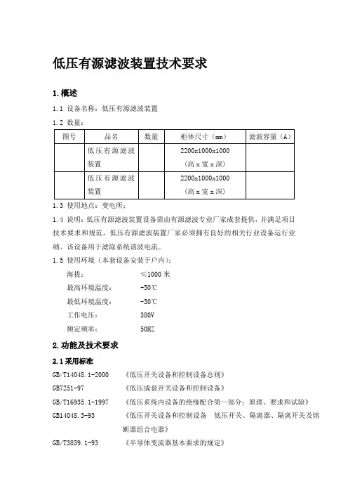
低压有源滤波装置技术要求1.概述1.1 设备名称:低压有源滤波装置1.2 数量:1.3 使用地点:变电所;1.4 说明:低压有源滤波装置设备需由有源滤波专业厂家成套提供,并满足项目技术要求和规范,低压有源滤波装置厂家必须拥有良好的相关行业设备运行业绩。
该设备用于滤除系统谐波电流。
1.5 使用环境(本套设备安装于户内):海拔:≤1000米最高环境温度: +50℃最低环境温度: -30℃工作电压: 380V额定频率: 50HZ2.功能及技术要求2.1采用标准GB/T14048.1-2000 《低压开关设备和控制设备总则》GB7251-97 《低压成套开关设备和控制设备》GB/T16935.1-1997 《低压系统内设备的绝缘配合第一部分:原理、要求和试验》GB14048.3-93 《低压开关设备和控制设备低压开关、隔离器、隔离开关及熔断器组合电器》GB/T3859.1-93 《半导体变流器基本要求的规定》GB3983.1-89 《低电压并联电容器》JB7113-1993 《低电压并联电容器装置》GB50052-95 《供配电系统设计规范》GB50054-95 《低压配电设计规范》JGJ/T16-92 《民用建筑电气设计规范》DGJ08-100-2003 《低压用户电气装置规程》IEC 61642 《受谐波影响的工业交流电网、过滤器和并联电容器的应用》IEC 61000-2-4 《电磁兼容(EMC).第2部分:环境—第4分部分:工厂低频传导骚扰兼容水平》IEC 61000-4-7 《电磁兼容(EMC)—第4部分:试验和测量技术—第7分部分:供电系统及所连设备谐波和谐间波和测量和测量仪器导则》GB/T12325-2003 《电能质量供电电压允许偏差》GB 12326-2000 《电能质量电压波动和闪变》GB/T 14549-93 《电能质量公用电网谐波》GB/T 15543-1995 《电能质量三相电压允许不平衡度》GB/T 15945-1995 《电能质量电力系统频率允许偏差》2.2 技术性能及要求2.2.1低压有源滤波装置为封闭式户内成套设备,其功能为用于系统谐波滤除。
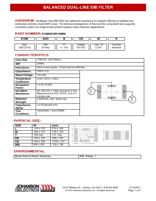
OVERVIEW: Multilayer chip EMI Filter has balanced impedance for superior filtering of radiated andconducted common-mode EMC noise. The terminal arrangement of this low ESL component also supports connection option for single-ended (power bypass) noise reduction applications .PART NUMBER: E18M0035B100MNE18M 0035 B 100 M NSize 1206 (3216)SRF 35 MHzTC +/- 15%Voltage 100 VDCCap. Tol ± 20%Terminal StandardCHARACTERISTICS:Case Size 1206 EIA (3216 Metric) SRF 35MHzInductance: 56pH power bypass, 212pH dual-line EMI filter Capacitance: 100nF (x 2)Rated Voltage: 100 VDCTemperature Coefficient: ±15% (-55 to +125C) Dissipation Factor: ≤ 2.5% (0.025)Insulation Resistance: IR> 500 Ω•F or 10G Ω whichever is less Measurement at 25C, WVDC, time is 2 minutes max.Dielectric Strength: 2.5XWVDC, 25C, 50mA max. Capacitance Aging: ≤ 2.5%/decade hour TestConditions:1kHz±50Hz; 1.0±0.2VRMSPHYSICAL SIZE:SIZE IN(mm)L.124 ± .0103.15 ± .254 W .063 ± .010 1.60 ± .254 T .050 max. 1.27 max. EB .016 ± .010 .406 ± .254 CB .040 ± .005 1.016 ± .127 WB006 ± .004.152 ± .100ENVIRONMENTALMeets Rohs & Reach directives MSL Rating: 1EMI FILTER INSERTION LOSSDUAL LINE CONNECTION* PWR BYPASS CONNECTION*EMC performance is a function both insertion loss and impedance matching / low noise-mode conversion. Connection graphics are representative, not all possible options are shown.PCB layout is critical for correct RF response. Technical support is available for new designs. SOLDER PAD RECOMMENDATIONS:SOLDER PROCESS RECOMMENDATIONS:SOLDER REFLOW: Recommended temperature profiles for reflow soldering are shown in Table 1 and Figure 1 from J-STD-020CPreheat ramp: 1-3C/sec.Preheat: 75-125C < T (max)T (max): 210-260CSOLDER WAVE: Caution, NOT recommended for sizes >1206Preheat Temp.:100-120C∆ T Pre-Heat: 150C max.Soldering Peak Temp.:250-260C, 5 SEC. max.Cool Down: <2C/SECSOLDERING IRON:NOT SUPPORTED for use in mass productionNot recommended for lab proto-typing, use solder reflow, hot-air tool, or conductive epoxy to avoid thermal damage and compromised test results. If Iron is used, follow below precautions:•Preheat circuit and capacitors to within 100° C of soldering temperature•No contact of iron tip with component•20 watt iron output (max)•350° C tip temperature (max)• 1.0 mm tip diameter (max)•Limit soldering time to 3 sec. (max)PACKAGING SPECIFICATIONSSpecification EIA standard 481PART SIZE 7” REEL QTY1206 (3216) 4,000Notice: Specifications are subject to change without notice. Contact your nearest Johanson Dielectrics, Inc. Sales Office for the latest specifications. All statements, information and data given herein are believed to be accurate and reliable, but are presented without guarantee, warranty, or responsibility of any kind, expressed or implied. Statements or suggestions concerning possible use of our products are made without representation or warranty that any such use is free of patent infringement and are not recommendations to infringe any patents. The user should not assume that all safety measures are indicated or that other measures may not be required. Specifications are typical and may not apply to all applications.。

目录CONTENTS01公司介绍02无源滤波器的应用现状及存在的问题03无源滤波的基本原理及特点04无源滤波装置的构成05无源滤波产品介绍06无源滤波器能解决的问题07无源滤波-典型应用10 典型案例11 订货须知11 服务公司介绍INTRODUCTION公司概况长沙博立电气有限公司重要从事电气、自控以及仪器仪表技术的研发、生产和销售,及有关信息技术服务、咨询和培训。
公司技术依靠湖南大学电气与信息工程学院、湖南省电气科学及其应用重点实验室、机械工业配电网电气节能重点实验室。
拥有柔性交流输电实验平台、高电能质量输配电实验等平台,有一批由专家、博士、工程技术人员等构成的科研和工程队伍,曾承当并圆满完毕了国家“863”计划、国家中小型公司创新基金等项目。
开发的高低压无功赔偿和谐波治理装备、配电综合自动化系统、大功率整流和监视系统已广泛地应用到电力、冶金等行业中,达成了公司电气节能降耗、提高电能质量和自动化水平的目的。
研发力量公司拥有一支由多人构成的科研队伍,科技人员含有坚实的理论基础和丰富的实践经验,严谨的科学作风和团结攻关的协作精神。
梯队职称构造、专业构造和年纪构造合理,文化程度均在大学本科以上,拥有多名博士、硕士硕士,专业涵盖电气工程、自动化、计算机应用、电力电子、软件、通信、数学等学科。
其中大部分人员始终以来都在大功率混合有源滤波器(HAPF)、静止无功赔偿器(SVC)、配电静止无功发生器(SVG/DSTATCOM)、智能无功赔偿器(IVC)、现场总线网络化控制系统(NCS)、分布式电气节能综合自动化系统以及全局协同优化节能控制软件等方面的研究工作,在高低压电气节能和管理节能方面含有一定基础和丰富的工程经验。
研究成果现在,公司有了一定的前期研究成果,“输配电核心技术与装备及其工程应用”“高低压先进无功赔偿技术和系列装备及其工程应用” “混合型大功率有源电力滤波器理论和装备及其工程应用” “供配电综合自动化技术及其工程应用”已通过由省级科技鉴定。

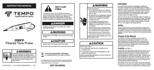
200FPFiltered Tone ProbeDescriptionThe 200FP Filtered Tone Probe is designed to identify andtrace wires or cables within a group without need of removinginsulation. In addition, the 200FP has been specifically designed tofilter out all power-related noise to eliminate “Power Line Hum.”The unit is constructed of durable ABS plastic, and an optionalleather carrying case, 200C, is available.The 200FP is alsoavailable as part of the Model 801K kit.When the 200FP is ON but not detecting a signal, the signal LEDwill flash momentarily (every 4 seconds) as a visible ON indicatorand reminder. When a tone signal is detected by the probe, thesignal LED will serve as a signal strength indicator.The brighterthe LED, the stronger the tone signal detected.SafetySafety is essential in the use and maintenance of Tempo Toolsand equipment. This instruction manual and any markings on thetool provide information for avoiding hazards and unsafe practicesrelated to the use of this tool. Observe all of the safety informationprovided.Purpose of this ManualThis manual is intended to familiarize personnel with thesafe operation and maintenance procedures for the TempoCommunications 200FP Filtered Tone Probe. Please read thisentire manual before operating the tool, and keep this manualavailable to all personnel. Replacement manuals are availableupon request at no extra charge.Controls (See Figure 1)A long press of the main control button turns the unit OFF or ON,and the unit beeps to indicate the change. A lower pitch beepindicates that the unit is going OFF. An Auto-Off feature hasbeen incorporated to turn the 200FP OFF after 5 minutes to helppreserve battery life. When Auto-Off activates, a bee-bee-bee-beep sounds from the speaker to alert the user that the 200FP isnow OFF. When the battery voltage is low, the unit sounds threedescending tones when it is turned ON.Short presses of the main control button engage and disengagethe hum filter of the 200FP. The unit beeps to indicate the change– a single beep means it is entering the normal unfiltered mode, 52080289 REV01 © 2019 Tempo Communications Inc. 08/19Do not discard this product or throw away!For recycling information, go to .All specifications are nominal and may change as design improvementsoccur. Tempo Textron Inc. shall not be liable for damages resulting frommisapplication or misuse of its products.KEEP THIS MANUALmode the LED indicator operates in red color, and in filter mode the LED appears green.A volume control knob located on the right side of the 200FPallows the user to control the sensitivity and loudness of the probe output.OperationIdentification of wires and cables is accomplished by first connecting a tracing tone generator like the TempoCommunications 77HP , 77GX or AT8 to the wires being traced.In working cables that are terminated, connect one lead of the tone generator to a wire and the other test lead to earth or equipment ground. This allows localization of the cable and un-terminated cables, 1. To activate the 200FP , use a long press of the square main control button.Note: Changes in temperature and battery power can affect the frequency of tones produced by any given tone generator. Under certain conditions, a tone test set may produce frequencies that are similar to power line hum and cause them to be blocked by the 200FP’s filter mode.2. Prior to locating the tone at the far end of the cable or wire, confirm proper operation of the 200FP at the tone source. With the probe ON and in the filter mode (a short press of the control button and a green LED blink), listen for a solid single tone or a complete warble tone at the tone generator. If no tone or only “half ”of a warble tone is detected, use the 200FP in the “Normal” unfiltered setting or replace the battery in the tone generator.3. Once activated, the volume control can be adjusted to suit the environment. Loudness of the probe tone output can be increased to overcome noise (i.e., vehicular traffic, airplanes or machinery) or decreased to reduce interference or when working in noise sensitive areas.4. The 200FP is equipped with recessed ports for connecting a lineman’s butt set. Attaching the butt set automatically activates the probe when Talk mode is selected on the set.5. To activate the 200FP without depressing the main control button, silence the speaker, and use only the LED, attach a jumper between the two recessed tabs. This simulates connection of a butt set.6. Touch the tip of the 200FP to the insulation of each potential target conductor.7. Reception of tone will be loudest on the subject wire. (Reception of the tone may be improved by separating the wires from the group.)SpecificationsElectricalNominal Gain: 35 dBNominal Input Impedance: 100 MΩProbe Tip Resistance (minimum): 300 ΩBattery: One 9V alkalineNominal Battery Life: 50 hoursOvervoltage Protection: Cat I, 150V to GndPhysicalLength: 250 mm (9.85")Width: 32 mm (1.27")Depth: 35 mm (1.38")Weight: 142 g (5 oz)Operating/Storage ConditionsTemperature: 0 °C to 50 °C (32 °F to 122 °F)MaintenanceBattery Replacement1. Turn the unit off.2. Remove the screw, then the battery door.3. Replace the battery (observe polarity).4.Replace the back and the screws. Do not overtighten the screw.Tip Replacement1. Turn the unit off.2. Remove the slotted screw and remove tip cover.3. Replace the tip.4.Replace tip cover and screw. Do not overtighten the screw.CleaningPeriodically wipe with a damp cloth and mild detergent; do not use abrasives or solvents.One-Year Limited WarrantyTempo Communications Inc. warrants to the original purchaser of these goods for use that these products will be free from defects in workmanship and material for one year, excepting normal wear and abuse.For all Test Instrument repairs, you must first request a Return Authorization Number by contacting our Customer Service department at:toll free in the US and Canada 800 642-2155. Telephone +1 760 510-0558. Facsimile +1 760 598-5634.This number must be clearly marked on the shipping label. Ship units Freight Prepaid to: Tempo Repair Center, 1390 Aspen Way, Vista, CA 92081 USA. Mark all packages: Attention: TEST INSTRUMENT REPAIR.For items not covered under warranty (such as dropped, abused, etc.) repair cost quote available upon request.Note: Prior to returning any test instrument, please check to make sure batteries are fully charged.Tempo Communications1390 Aspen Way • Vista, CA 92081 • USA。
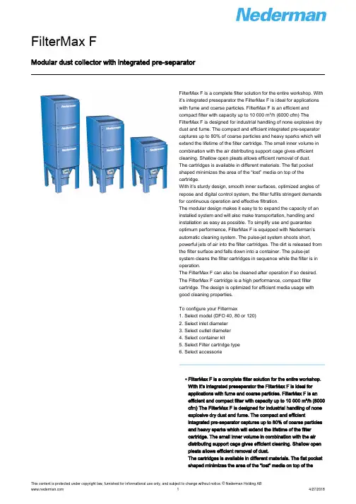
Modular dust collector with integrated pre-separatorFilterMax F is a complete filter solution for the entire workshop. Withit’s integrated preseparator the FilterMax F is ideal for applicationswith fume and coarse particles. FilterMax F is an efficient andcompact filter with capacity up to 10 000 m³/h (6000 cfm) TheFilterMax F is designed for industrial handling of none explosive drydust and fume. The compact and efficient integrated pre-separatorcaptures up to 80% of coarse particles and heavy sparks which willextend the lifetime of the filter cartridge. The small inner volume incombination with the air distributing support cage gives efficientcleaning. Shallow open pleats allows efficient removal of dust.The cartridges is available in different materials. The flat pocketshaped minimizes the area of the “lost” media on top of thecartridge.With it’s sturdy design, smooth inner surfaces, optimized angles ofrepose and digital control system, the filter fulfils stringent demandsfor continuous operation and effective filtration.The modular design makes it easy to to expand the capacity of aninstalled system and will also make transportation, handling andinstallation as easy as possible. To simplify use and guaranteeoptimum performance, FilterMax F is equipped with Nederman’sautomatic cleaning system. The pulse-jet system shoots short,powerful jets of air into the filter cartridges. The dirt is released fromthe filter surface and falls down into a container. The pulse-jetsystem cleans the filter cartridges in sequence while the filter is inoperation.The FilterMax F can also be cleaned after operation if so desired.The FilterMax F cartridge is a high performance, compact filtercartridge. The design is optimized for efficient media usage withgood cleaning properties.To configure your Filtermax1. Select model (DFO 40, 80 or 120)2. Select inlet diameter3. Select outlet diameter4. Select container kit5. Select Filter cartridge type6. Select accessorie• FilterMax F is a complete filter solution for the entire workshop.With it’s integrated preseparator the FilterMax F is ideal forapplications with fume and coarse particles. FilterMax F is anefficient and compact filter with capacity up to 10 000 m³/h (6000cfm) The FilterMax F is designed for industrial handling of noneexplosive dry dust and fume. The compact and efficientintegrated pre-separator captures up to 80% of coarse particlesand heavy sparks which will extend the lifetime of the filtercartridge. The small inner volume in combination with the airdistributing support cage gives efficient cleaning. Shallow openpleats allows efficient removal of dust.The cartridges is available in different materials. The flat pocketshaped minimizes the area of the “lost” media on top of thecartridge.With it’s sturdy design, smooth inner surfaces, optimized angles of repose and digital control system, the filter fulfils stringent demands for continuous operation and effective filtration.The modular design makes it easy to to expand the capacity of an installed system and will also make transportation, handling and installation as easy as possible. To simplify use and guarantee optimum performance, FilterMax F is equipped with Nederman’s automatic cleaning system. The pulse-jet system shoots short, powerful jets of air into the filter cartridges. The dirt is released from the filter surface and falls down into a container. The pulse-jet system cleans the filter cartridges in sequence while the filter is in operation.The FilterMax F can also be cleaned after operation if so desired.The FilterMax F cartridge is a high performance, compact filter cartridge. The design is optimized for efficient media usage with good cleaning properties.To configure your Filtermax1. Select model (DFO 40, 80 or 120)2. Select inlet diameter3. Select outlet diameter4. Select container kit5. Select Filter cartridge type6. Select accessorie• Pulse-jet cleaning system• Pulse-jet cleaning system• Integrated pre-separator / spark trapFumes DustImage*Only for ordering with a FilterMax F. Part numbers for replacement filter cartridges can be found in the instruction manual or .**Welding fume category W3 means that the unit is able to reliably extract and clean low, medium and highalloyed steels, e.g. containing a part of nickel and chrome of 30% and more with a separation efficiency of ≥99%. With this kit the FilterMax F is certified according to the international effective standard DIN EN ISO 15012-1 (2005) that controls industrial and health protection for welding and related processes and the requirements,examination and identification of air cleaning systems.The height dimensions are valid with a 40 l / 10.5 gallon bin. If a 100 l / 26.5 gallon bin is used add 450 mm / 18”.Pressure drop for Inlet and outlet. Actual working pressure will depend on application and dimensioning. Dimensional typical pressure drop for FilterMax 1200 Pa (5" WG)。
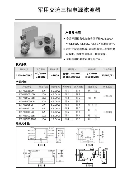
军用交流三相电源滤波器
产品及应用
●专为军用设备电磁兼容国军标GJB152A 中CE102、CE106、CE107标准而设计。
●应用于发射机电源、雷达电源等三相供电制设备中。
特殊质量要求,性能可靠。
●可根据用户要求定制专用产品。
技术参数
额定电压 工作频率 额定电流 耐压测试 绝缘电阻 气候类别 115~440VAC
50/60Hz /400Hz
1~200A
线-线:1450VDC 线-地:1500VAC
≥200M Ω @1000VDC
55/85/21
产品列表
产品型号 额定电流 泄露电流 外型尺寸 插入损耗 连接方式 供电制式
ET-M5C21LW
5A ≤5.0mA
图1 图1 软 线
ET-M10C21EB 10A ≤5.0mA 图2 图2 ET-M15C21EB 15A ≤5.0mA 图2 图2 ET-M20C30LB 20A ≤5.0mA 图3 图3 螺 栓 三相三线 ET-M3D30ET 3A ≤5.0mA 图4 图4 端 子 排 ET-M5D22LW 5A ≤5.0mA 图5 图5 ET-M6D21LW
6A ≤5.0mA
图6 图6 软 线 ET-M10D21LB 10A ≤5.0mA 图7 图7 螺 栓 ET-M15D33OW 15A ≤5.0mA
图8
图8
软 线
三相四线
外形尺寸图:
【图1】 【图2】
【图3】
【图5】【图6】
【图7】【图8】插入损耗:。
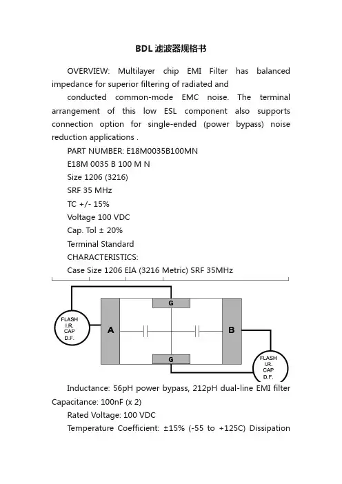
BDL滤波器规格书OVERVIEW: Multilayer chip EMI Filter has balanced impedance for superior filtering of radiated andconducted common-mode EMC noise. The terminal arrangement of this low ESL component also supports connection option for single-ended (power bypass) noise reduction applications .PART NUMBER: E18M0035B100MNE18M 0035 B 100 M NSize 1206 (3216)SRF 35 MHzTC +/- 15%Voltage 100 VDCCap. Tol ± 20%Terminal StandardCHARACTERISTICS:Case Size 1206 EIA (3216 Metric) SRF 35MHzInductance: 56pH power bypass, 212pH dual-line EMI filter Capacitance: 100nF (x 2)Rated Voltage: 100 VDCTemperature Coefficient: ±15% (-55 to +125C) DissipationFactor: ≤ 2.5% (0.025)Insulation Resistance: IR> 500 Ω?F or 10G Ω whichever is less Measurement at 25C, WVDC, time is 2 minutes max.Dielectric Strength: 2.5XWVDC, 25C, 50mA max. Capacitance Aging: ≤ 2.5%/decade hour TestConditions:1kHz±50Hz; 1.0±0.2VRMSPHYSICAL SIZE:SIZE IN(mm)L.124 ± .0103.15 ± .254 W .063 ± .010 1.60 ± .254 T .050 max. 1.27 max. EB .016 ± .010 .406 ± .254 CB .040 ± .005 1.016 ± .127 WB 006 ± .004.152 ± .100ENVIRONMENTALMeets Rohs & Reach directives MSL Rating: 1EMI FILTER INSERTION LOSSDUAL LINE CONNECTION* PWR BYPASS CONNECTION*EMC performance is a function both insertion loss and impedance matching / low noise-mode conversion. Connection graphics are representative, not all possible options are shown.PCB layout is critical for correct RF response. Technical support is available for new designs. SOLDER PAD RECOMMENDATIONS:SOLDER PROCESS RECOMMENDATIONS:SOLDER REFLOW: Recommended temperature profiles for reflow soldering are shown in Table 1 and Figure 1 from J-STD-020CPreheat ramp: 1-3C/sec.Preheat: 75-125C < T (max)T (max): 210-260CSOLDER WAVE: Caution, NOT recommended for sizes >1206Preheat Temp.:100-120CT Pre-Heat: 150C max.Soldering Peak Temp.:250-260C, 5 SEC. max.Cool Down: <2C/SECSOLDERING IRON:NOT SUPPORTED for use in mass productionNot recommended for lab proto-typing, use solder reflow, hot-air tool, or conductive epoxy to avoid thermal damage and compromised test results. If Iron is used, follow below precautions:Preheat circuit and capacitors to with in 100° C of soldering temperatureNo contact of iron tip with component20 watt iron output (max)350° C tip temperature (max)1.0 mm tip diameter (max)Limit soldering time to 3 sec. (max)PACKAGING SPECIFICATIONSSpecification EIA standard 481PART SIZE 7” REEL QTY1206 (3216) 4,000Notice: Specifications are subject to change without notice. Contact your nearest Johanson Dielectrics, Inc. Sales Office for the latest specifications. All statements, information and data given herein are believed to be accurate and reliable, but are presented without guarantee, warranty, or responsibility of any kind, expressed or implied. Statements or suggestions concerning possible use of our products are made without representation or warranty that any such use is free of patent infringement and are not recommendations to infringe any patents. The user should not assume that all safety measures are indicated or that other measures may not be required. Specifications are typical and may not apply to all applications.。
滤波器通用质量特性保障大纲
一、滤波器(filter)通用质量特性保障大纲概述
滤波器通用质量特性保障大纲旨在提供一个质量保证指南,用于评估和核实滤波器所使用的通用组件的质量特性。
质量特性以机械和电气性能的标准度量格式作为指标。
这规定了滤波器的机械和电气性能应满足的标准,特别是基于军事标准的电气质量,能够提供滤波器运行的安全操作保障,可靠的性能表现,抗电磁干扰性强等特点,降低过程变量的测量错误和故障几率,从而达到“高品质,性价比高”。
二、滤波器通用质量特性保障大纲内容
1、外壳特性:滤波器外壳由军标完成框结构组成,材料采用环保型电气材料,形式标准,外形整洁,无剂有缺陷,能够满足高低温、潮湿等变化的环境工况要求。
2、绝缘性:滤波器绝缘性良好,高电压持久抗绝缘的特性要符合军标要求,提高电气安
全性和可靠性。
3、电性能:滤波器电性能要满足信号传输特性及控制精度需求。
抗电磁干扰能力要符合JIS和军标规定,提高滤波器的安全性、精准性和性能可靠性。
4、机械性能:滤波器的机械性能要达到额定动态性能、轴向结构的强度、耐磨性、密封
性和外形尺寸等要求,滤波器运行时不会发生机械损坏以及表面磨损。
三、滤波器通用质量特性保障大纲的重要性
滤波器应用于许多场合,处理的都是电信号及信息,有时还会加上控制和查询操作,因此,质量控制对滤波器的性能和可靠性起到非常重要的作用。
滤波器通用质量特性保障大纲提供了一套系统的质量保证实施指南,以确保滤波器在运行中能够正常、安全、可靠地发挥
作用,为使用者提供便利和保障。
滤波器的主要参数(Definitions):中心频率(Center Frequency):滤波器通带的中心频率f0,一般取f0=(f1+f2)/2,f1、f2为带通或带阻滤波器左、右相对下降1dB或3dB边频点。
窄带滤波器常以插损最小点为中心频率计算通带带宽。
截止频率(Cutoff Frequency):指低通滤波器的通带右边频点及高通滤波器的通带左边频点。
通常以1dB或3dB相对损耗点来标准定义。
相对损耗的参考基准为:低通以DC处插损为基准,高通则以未出现寄生阻带的足够高通带频率处插损为基准。
通带带宽(BWxdB):指需要通过的频谱宽度,BWxdB=(f2-f1)。
f1、f2为以中心频率f0处插入损耗为基准,下降X(dB)处对应的左、右边频点。
通常用X=3、1、0.5 即BW3dB、BW1dB、BW0.5dB 表征滤波器通带带宽参数。
分数带宽(fractional bandwidth)=BW3dB/f0×100[%],也常用来表征滤波器通带带宽。
插入损耗(Insertion Loss):由于滤波器的引入对电路中原有信号带来的衰耗,以中心或截止频率处损耗表征,如要求全带内插损需强调。
纹波(Ripple):指1dB或3dB带宽(截止频率)范围内,插损随频率在损耗均值曲线基础上波动的峰-峰值。
带内波动(Passband Riplpe):通带内插入损耗随频率的变化量。
1dB带宽内的带内波动是1dB。
带内驻波比(VSWR):衡量滤波器通带内信号是否良好匹配传输的一项重要指标。
理想匹配VSWR=1:1,失配时VSWR>1。
对于一个实际的滤波器而言,满足VSWR<1.5:1的带宽一般小于BW3dB,其占BW3dB的比例与滤波器阶数和插损相关。
回波损耗(Return Loss):端口信号输入功率与反射功率之比的分贝(dB)数,也等于|20Log10ρ|,ρ为电压反射系数。
输入功率被端口全部吸收时回波损耗为无穷大。
1AC Filter 2-Stage, excellent AttenuationCase MECase MBCase MFSee below:Approvals and CompliancesDescription- Line filter in standard and medical version - 2 stage- Compact design- Very light due to partial pottingUnique Selling Proposition- Excellent differential and common-mode attenuation - Broad band attenuation- Completely closed steel housing - Wide temperature rangeCharacteristics- Designed for current applications of 1 - 36 A- Protection against interference voltage from the mainsPossible interferences generated in the equipment are strongly attenu-ated- Especially designed for industrial applications such as: Frequency Con-verters, Stepper Motor Drives, UPS-Systems, Inverters- Suitable for use in equipment according to IEC/UL 62368-1Suitable for use in medical equipment according to IEC/UL 60601-1References Alternative: High attenuation version FMBB NEOWeblinkspdf data sheet , html datasheet , General Product Information , Approvals , Distributor-Stock-Check , Detailed request for product , MicrositeT echnical DataRatings IEC1 - 36 A @ Ta 40 °C / 250 VAC; 50 Hz Ratings UL/CSA 1 - 36 A @ Ta 40 °C / 125/250 VAC; 60 HzLeakage Currentstandard < 0.5 mA (250 V / 60 Hz) medical (M5) < 5 µA resp. (M80) < 80 µA (250 V / 60 Hz)Dielectric Strength1.7 kVDC between L-N2.7 kVDC between L/N-PE Test voltage (2 sec)Allowable Operation Tempe-rature-40 °C to 100 °CClimatic Category 40/100/21 acc. to IEC 60068-1IP-Protection from rear-side IP20 IEC 60529Protection Class Suitable for appliances with protection class I acc. to IEC 61140Terminal Quick connect terminal 6.3 x 0.8 mm Bolt and nut M4Material: HousingNickel plated steelLine FilterStandard and Medical Version, IEC 60939, UL 60939-3, CSA C22.2 no. 8 Technical DetailsMTBF> 200'000 h acc. to MIL-HB-217 FApprovals and CompliancesDetailed information on product approvals, code requirements, usage instructions and detailed test conditions can be looked up in Details about ApprovalsSCHURTER products are designed for use in industrial environments. They have approvals from independent testing bodies according to national and international standards. Products with specific characteristics and requirements such as required in the automotive sector according to IATF 16949, medical technology according to ISO 13485 or in the aerospace industry can be offered exclusively with customer-specific, individual agree-ments by SCHURTER.ApprovalsThe approval mark is used by the testing authorities to certify compliance with the safety requirements placed on electronic products. Approval Reference T ype: FMBB EPApproval Logo Certificates Certification Body DescriptionVDE Approvals VDE Certificate Number: 40051449UL Approvals UL UL File Number: E495089Product standardsProduct standards that are referencedOrganization Design StandardDescriptionDesigned according to IEC 60939Passive filters for suppressing electromagnetic interferenceDesigned according to IEC 60127-6Miniature fuses. Part 6. Fuse-holders for miniature fuse-linksDesigned according to UL 60939-3Electromagnetic interference filtersDesigned according to CSA C22.2 no. 42General Use Receptacles, Attachment Plugs, and Similar Wiring DevicesDesigned according to CSA C22.2 no. 8Electromagnetic interference (EMI) filters Application standardsApplication standards where the product can be usedOrganization Design StandardDescriptionDesigned for applications acc.IEC/UL 62368-1IEC 62368-1 includes the basic requirements for safety of audio, video,information technology and office equipment.Designed for applications acc.IEC 60601-1Medical electrical equipment - Part 1: General requirements for basicsafety and essential performanceCompliancesThe product complies with following Guide LinesIdentification Details Initiator DescriptionCE declaration of conformity SCHURTER AG The CE marking declares that the product complies with the applicablerequirements laid down in the harmonisation of Community legislation onits affixing in accordance with EU Regulation 765/2008.RoHS SCHURTER AG Directive RoHS 2011/65/EU, Amendment (EU) 2015/863China RoHS SCHURTER AG The law SJ / T 11363-2006 (China RoHS) has been in force since 1 March2007. It is similar to the EU directive RoHS.REACH SCHURTER AG On 1 June 2007, Regulation (EC) No 1907/2006 on the Registration,Evaluation, Authorization and Restriction of Chemicals 1 (abbreviated as"REACH") entered into force.Medical Equipment SCHURTER AG Suitable for use in medical equipment according to IEC/UL 60601-12Dimension [mm]Case 09 with quick connect terminals1) Line2) LoadCase MB with bolt and nut M41) Line2) Load3) Nut torque 0.8...1 Nm, keep lock-nut fastened4) Lock-nut do not unscrew5) PE: M4x16, 1.2...1.5 Nm, keep lock-nut fastened3Case MC with quick connect terminals1) Line2) LoadCase MD with quick connect terminals1) Line2) Load4Case ME with quick connect terminals1) Line2) LoadCase MF with bolt and nut M41) Line2) Load3) Nut torque 0.8...1 Nm, keep lock-nut fastened4) Lock-nut do not unscrew5) PE: M4x16, 1.2...1.5 Nm, keep lock-nut fastened56DiagramsStandard and medical M801)2)1) Line, 2) LoadMedical M51)2)Attenuation Loss . . . . . 0.1/100Ω differential mode ........... 100/0.1Ω differential mode - - - - 50Ω differential mode _____ 50Ω common mode Standard version1A3A6A10 A12 A16 A20 A30 A36 AAll VariantsThe specifications, descriptions and illustrations indicated in this document are based on current information. All content is subject to modifications and amendments. Information furnished is believed16.7.227。
滤波器的主要参数(Definitions):欧阳家百(2021.03.07)中心频率(Center Frequency):滤波器通带的频率f0,一般取f0=(f1+f2)/2,f1、f2为带通或带阻滤波器左、右相对下降1dB或3dB边频点。
窄带滤波器常以插损最小点为中心频率计算通带带宽。
截止频率(Cutoff Frequency):指低通滤波器的通带右边频点及高通滤波器的通带左边频点。
通常以1dB或3dB相对损耗点来标准定义。
相对损耗的参考基准为:低通以DC处插损为基准,高通则以未出现寄生阻带的足够高通带频率处插损为基准。
通带带宽(BWxdB):指需要通过的频谱宽度,BWxdB=(f2-f1)。
f1、f2为以中心频率f0处插入损耗为基准,下降X(dB)处对应的左、右边频点。
通常用X=3、1、0.5 即BW3dB、BW1dB、BW0.5dB 表征滤波器通带带宽参数。
分数带宽(fractional bandwidth)=BW3dB/f0×100[%],也常用来表征滤波器通带带宽。
插入损耗(Insertion Loss):由于滤波器的引入对电路中原有信号带来的衰耗,以中心或截止频率处损耗表征,如要求全带内插损需强调。
纹波(Ripple):指1dB或3dB带宽(截止频率)范围内,插损随频率在损耗均值曲线基础上波动的峰-峰值。
带内波动(Passband Riplpe):通带内插入损耗随频率的变化量。
1dB带宽内的带内波动是1dB。
带内驻波比(VSWR):衡量滤波器通带内信号是否良好匹配传输的一项重要指标。
理想匹配VSWR=1:1,失配时VSWR<1。
对于一个实际的滤波器而言,满足VSWR<1 BWdBBWdBdiv>在入射波和反射波相位相同的地方,电压振幅相加为最大电压振幅Vmax ,形成波腹;在入射波和反射波相位相反的地方电压振幅相减为最小电压振幅Vmin ,形成波节。
其它各点的振幅值则介于波腹与波节之间。
滤波器的主要参数(Definitions):中心频率(Center Frequency):滤波器通带的频率f0,一般取f0=(f1+f2)/2,f1、f2为带通或带阻滤波器左、右相对下降1dB或3dB边频点。
窄带滤波器常以插损最小点为中心频率计算通带带宽。
截止频率(Cutoff Frequency):指低通滤波器的通带右边频点及高通滤波器的通带左边频点。
通常以1dB或3dB相对损耗点来标准定义。
相对损耗的参考基准为:低通以DC处插损为基准,高通则以未出现寄生阻带的足够高通带频率处插损为基准。
通带带宽(BWxdB):指需要通过的频谱宽度,BWxdB=(f2-f1)。
f1、f2为以中心频率f0处插入损耗为基准,下降X (dB)处对应的左、右边频点。
通常用X=3、1、0.5 即BW3dB、BW1dB、BW0.5dB 表征滤波器通带带宽参数。
分数带宽(fractional bandwidth)=BW3dB/f0×100[%],也常用来表征滤波器通带带宽。
插入损耗(Insertion Loss):由于滤波器的引入对电路中原有信号带来的衰耗,以中心或截止频率处损耗表征,如要求全带内插损需强调。
纹波(Ripple):指1dB或3dB带宽(截止频率)范围内,插损随频率在损耗均值曲线基础上波动的峰-峰值。
带内波动(Passband Riplpe):通带内插入损耗随频率的变化量。
1dB带宽内的带内波动是1dB。
带内驻波比(VSWR):衡量滤波器通带内信号是否良好匹配传输的一项重要指标。
理想匹配VSWR=1:1,失配时VSWR<1。
对于一个实际的滤波器而言,满足VSWR<1 BWdBBWdBdiv>在入射波和反射波相位相同的地方,电压振幅相加为最大电压振幅Vmax ,形成波腹;在入射波和反射波相位相反的地方电压振幅相减为最小电压振幅Vmin ,形成波节。
其它各点的振幅值则介于波腹与波节之间。