高品质电子镇流器使用说明书
- 格式:pdf
- 大小:143.21 KB
- 文档页数:4
ZP1500D 用户手册高压差分探头修订历史目录1.安全须知 (1)1.1一般性安全概要 (1)1.2警示标志 (1)1.2.1面板图标意义 (1)1.2.2测量类别介绍 (2)1.3测量类别 (3)1.4保养与清洁 (4)2.产品简介 (5)2.1产品应用 (5)2.2产品特色 (5)3.技术参数 (6)3.1技术指标 (6)3.2普通技术规格 (7)3.3配件 (8)4.快速入门 (9)4.1操作基础 (9)4.1.1面板说明 (9)4.1.2功能检测 (10)4.1.3操作步骤 (10)4.1.4注意事项 (11)5.常见问题 (14)5.1具体问题阐述 (14)5.1.1上电后面板指示灯全灭 (14)5.1.2调零输出值偏大或调零时间较长 (14)5.1.3测量波形不能稳定显示或误差明显 (14)6.性能验证 (15)6.1直流精度 (15)6.2方波响应 (15)6.3直流共模抑制比 (16)7.装箱单 (17)8.免责声明 (18)1.安全须知为保证您能正确安全地使用本仪器,请务必遵守以下注意事项。
如果未遵守本手册指定的方法操作本仪器,可能会损坏本仪器的保护功能。
因违反以下注意事项操作仪器所引起的损伤,广州致远电子有限公司不予以承担责任。
1.1 一般性安全概要了解下列安全性预防措施,以避免受伤,防止损坏本产品或本产品连接的任何产品。
使用推荐的电源适配器电源适配器为5V/2A USB输出,符合CB认证要求。
使用正常接地的示波器不建议探头信号输出端浮地,请将探头输出线缆连接到正常接地的示波器设备上。
查看所有终端额定值为避免起火和过大电流的冲击,请查看产品所有的额定值和标记。
产品使用前,请仔细阅读用户手册以了解额定值的详细信息。
请勿开盖操作请勿在仪器外壳打开时运行本产品。
避免电路外露电源接通后,请勿接触外露的接头和元件。
防止触电危险适配器必须插在墙壁上或在可视范围内的具有保护地的插排上,不可插在引线混乱的插排上,插排不可过流使用。
Congratulations on choosing our company product! We thank you for your custom.◆Please note that this product, as all the others in the rich my company range, hasbeen designed and made with total quality to ensure excellent performance andbest meet your expectations and requirements.◆Carefully read this user manual in its entirety and keep it safe for future reference.It is essential to know the information and comply with the instructions given in thismanual to ensure the fitting is installed, used and serviced correctly and safely.◆My company disclaims all liability for damage to the fitting or to other property orpersons deriving from installation, use and maintenance that have not been carriedout in conformity with this user manual, which must always accompany the fitting.◆My company reserves the right to modify the characteristics stated in this usermanual at any time and without prior notice.感谢您选用我们公司的产品。
电子镇流器目录摘要电子镇流器(Electricalballast),是镇流器的一种,是指使用电子技术驱动电光源,使之产生所需照明的电子设备。
与之对应的是电感式镇流器(或者镇流器)。
现代日光灯越来越多的使用电子镇流器,轻便小巧,甚至能够将电子镇流器与灯管等集成在一起,同时,电子镇流器通常能够兼具起辉器功能,故此又可省去单独的起辉器。
电子镇流器还能够具有更多功能,比如能够通过提高电流频率或者者电流波形(如变成方波)改善或者消除日光灯的闪烁现象;也可通过电源逆变过程使得日光灯能够使用直流电源。
电子镇流器-基本概述电子镇流器电子镇流器-基本分类DC 24V电子镇流器按安装模式可分为:(1)独立式(2)内装式(3)整体式按性能特点可分为:(1)普通型,0.6≥120%90%1.4~1.6高频化使之小型、轻、有节电功能;(2)高功率因数型H级,≥0.9≤30%≤18%1.7~2.1使用无源滤波与特殊保护;(3)高性能电子镇流器L级,≥0.95≤20%≤10%1.4~1.7有完善的特殊保护功能,电磁兼容;(4)高性价比电子镇流器L级,≥0.97≤10%≤5%1.4~1.7集成技术与恒功率电路设计,电压波动影响照度小;(5)可调光电子镇流器,≥0.96≤10%≤5%≤1.7使用集成技术与有源可变频率谐振技术。
电子镇流器-应用领域石英灯电子镇流器1、一拖一、一拖二灯箱专用电子镇流器是专门为户外灯箱,广告牌而设计的。
优势有下列几个方面:(1)使用安全绝缘性能高,防水防潮性能好,镇流器温升低,不可能影响灯箱布或者灯箱片因受热而变黄。
(2)方便:2、一拖一、一拖二普通型电子镇流器适用于各类普通照明场合灯具的安装与更换;电子镇流器-要紧优点电子镇流器电子镇流器-选用建议35W声光电子镇流器电子镇流器对提高照明系统能效与质量有明显优势,是新国际推荐应用的产品,也是未来进展的趋势。
(3)应选用高品质、低谐波的产品,不应单纯追求价廉,应满足使用的技术要求,考虑运行保护效果,并作综合比较。
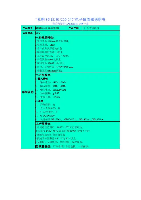
高压钠灯智能调光型电子镇流器安装使用说明书 大明(FITBRIGHT )公司HPS 系列高压钠灯智能调光型电子镇流器,具有高功率因数,低谐波,恒功率输出,提高光效,性能稳定,以及具有防潮、异常状态保护功能等特点。
广泛应用于城市道路、施工现场、桥梁、铁路、隧道、商场、工厂、宾馆、机场码头、泛光照明等。
一、产品性能特点1、绿色照明,高效照明;2、低谐波(<8%),高功率因数(>0.99);3、输出端短路、断路保护功能;4、恒功率输出,相匹配的光源无频闪;5、智能调光电子镇流器会自动完成过程控制。
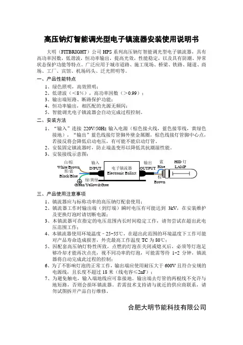
二、安装方法1、“输入”连接220V/50Hz 输入电源(棕色接火线,蓝色接零线,黄绿色接地),“输出”蓝色线接灯管脚外壁金属圈,棕色线接灯管脚中心点,若接反将会降低启动电压,有可能不能启动灯管。
2、安装固定镇流器时,防止端盖变形以降低其抗潮湿性能。
3、安装接线示意图:三、产品使用注意事项 1、镇流器应与标称功率的高压钠灯配套使用;2、镇流器工作时输出端(到灯端)瞬时电压有可能达到3kV ,在安装维护及更换灯泡时请切断电源;3、本镇流器可在指定的电压范围内长时间稳定工作,请勿尝试在超出此电压范围工作;4、本镇流器使用环境温度﹣25~55℃,在超出此范围的环境温度下工作可能对产品寿命造成损害,外壳最高工作温度TC 为80℃;5、因配套高压钠灯特性所致,点燃的灯泡在关闭或熄灭后,必须等灯泡足够冷却才能再次点亮,视不同功率的灯泡,可能需等待1~2分钟,镇流器将自动完成此过程的控制;6、为了不影响灯泡的正常工作,输出端应使用耐压大于600V 且符合安规的电源线,且长度不超过18米(线电容≤2nF );7、为避免触电,输入端地线应可靠接地。
输出端去灯管的两根线不允许与地短路,否则会损坏镇流器。
若需技术支持请与就近的供应商联系,请勿试图拆开产品自行维修。
合肥大明节能科技有限公司 白/棕黑/蓝n。
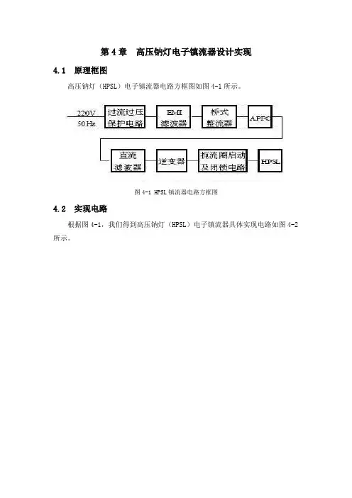
第4章高压钠灯电子镇流器设计实现4.1 原理框图高压钠灯(HPSL)电子镇流器电路方框图如图4-1所示。
图4-1 HPSL镇流器电路方框图4.2 实现电路根据图4-1,我们得到高压钠灯(HPSL)电子镇流器具体实现电路如图4-2所示。
图4-2 HPSL电子镇流器电路图下面对图4-2的各部分电路进行详细说明。
4.2.1 市电输入保护电路市电输入保护电路如图4-3所示。
图4-3 市电输入保护电路图中,FU为保险丝,在短路过流时起保护作用。
RT为负温度系数热敏电阻元件,用于抑制电源接通瞬间的浪涌电流冲击。
常温下RT呈高阻态,随着流过电流的增高,其温度也升高,而电阻值却下降,在负载电流达到稳定时,其阻值下降至最小,对电流产生的影响可忽略不计。
RV为压敏电阻,其阻值随电压的增高而急剧减小,可吸收诸如雷电等原因引起的电网瞬时高电压冲击。
因其耐受瞬时功率能力强,可长期工作。
正常状态下,RV接近开路,故对电路的影响可忽略。
本电路简单、低廉、有效。
4.2.2 EMI滤波器电磁干扰包括射频干扰(RFI)和各式各样的电磁脉冲干扰,它们的危害正受到愈来愈多的重视。
来自电网和电子镇流器逆变电路大功率高频振荡的射频传导干扰必须采用EMI滤波器加以隔离,以消除两者之间的互相干扰。
本电路采用双π型EMI滤波器,如图4-4所示。
其中,L1 = L2 , C1 = C2 ,C3 = C4 。
由于电感对射频干扰起阻流作用,而小容量电容则对射频干扰起近似短路作用,故EMI滤波器对射频传导干扰的抑制作用是明显的。
图4-4 双π型EMI滤波器电磁脉冲干扰在相线与中线间产生差模(对称模式)干扰,与地线无关, L1 、L2 对此干扰电流呈高阻抗;而在每条电源线与地线之间会产生共模(非对称模式)干扰, C3 、C4 对此干扰呈低阻抗,所以EMI滤波器对电磁干扰能有效抑制。
如果EMI滤波器的阻抗设计与干扰源的阻抗不匹配,则EMI滤波器还能将干扰源的干扰沿其进入的路径反射回去,这样EMI滤波器的滤波效果更佳。
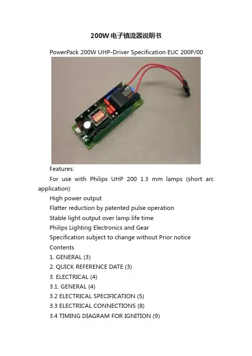
200W电子镇流器说明书PowerPack 200W UHP-Driver Specification EUC 200P/00Features:For use with Philips UHP 200 1.3 mm lamps (short arc application)High power outputFlatter reduction by patented pulse operationStable light output over lamp life timePhilips Lighting Electronics and GearSpecification subject to change without Prior noticeContents1. GENERAL (3)2. QUICK REFERENCE DATE (3)3. ELECTRICAL (4)3.1. GENERAL (4)3.2 ELECTRICAL SPECIFICATION (5)3.3 ELECTRICAL CONNECTIONS (8)3.4 TIMING DIAGRAM FOR IGNITION (9)4. MECHANICAL DIMENSIONS (10)5. MECHANICAL AND ENVIRONMENTAL RELIABILITY TESTS (11)6. SYNCHRONISE OPTION (12)6.1 GENERAL (12)6.2 TIMING DIAGRAM (12)6.3. TIMING SPECIFICATION (13)7. MARKING AND PACKING (14)7.1. MARKING (14)7.2. PACKING (14)8. INSTRUCTION FOR USE (14)Appendix 1: Mechanical drawing of the connector (15)1. GENERALThe lamp driver is capable to drive a short-arc 200W Philips UHP- lamp and controls the lamp power within narrow margins. The lamp driver in combination with the lamp will guarantee a stable light output over the specified lamp lifetime. The lamp driver itself has no mains isolation so the lamp connections are not mains isolated. The lamp driver can be driven by (isolated) input signals. An (isolated) output signal (“Flag”) indicates if the lamp operates correctly.The lamp circuit has no cover.The driver features a built-in option for synchronisation of the lamp current transitions, for which the SCI input can be used as described in chapter 6Note that when this option is NOT used, care must be taken never to apply any pulsating or block-shaped signals on this input; only DC levels (low or high) are allowed!Unless otherwise stated the specified values are valid under nominal operating conditions and measured according fig 1. Thelamp has reached a nominal condition or is warm after it has been burning for at least 10 minutes. A lamp is cold after it is turned off for at least 1 hour.WARNING: Driver is only allowed to operate when lamp socket is inserted into driver socket!2. QUICK REFERENCE DATEOutput (lamp) Power200WLamp current frequency (free running)88 Hz.Lamp Ignition voltage25kV peak.Input voltage280-400V DC operating; 160-400V DC standby.EMC standards*EN 55022; DENTORI; FCC CFR 47 part 18.Safety standards*(c-)UL1492, (c-) UL1950, EN/IEC60065 (6th ed. / 7-’98) and EN/IEC60950 (3rd ed. / 4-‘99).Markings CSA, CE, ENECMax. ambient temp.55°C with forced airflow 1.5ms-1.Dimensions (l*b*h)150*60*32 mm* The lampdriver is designed to meet these standards in the application. It is not designed to meet the requirements for ‘limited current’.Manufactured in an ISO 9001 approved factoryAll values are measured with a circuit according fig 3.1This specification is valid for all the following drivers:Driver type Cable length130mm Cable length160mmCable length190mmCable length230mmCable length280mmCable length340mmEUC 200 P/009137 001 570*9137 001 571*9137 001 541*9137 001 532*9137 001 572*9137 001 565* * indicates a 2-digit brandname; default 05 (no brand).3. ELECTRICAL3.1. GENERALAll values are measured with a circuit connected as shown in fig 3.1.Fig 3.1: Driver connections to supply, control signals and lamp.3.2 ELECTRICAL SPECIFICATIONThe lampdriver is tested with a circuit according fig 3.1The values as listed below are valid for all driver types except when indicated otherwise.Description Symbol value CommentMin typ max Unit1INPUTS1Power input1.1Inputvoltage, operating Vpi280350400V DC, or DC with ripple 100 or120Hz1.2Inputvoltage, non-operating Vpi,no160-400V1.4Min. voltage for driver tostart-upVpi,su280--V Non-operating to operating.1.5Voltage dip time to restartimmediately Tlow--1Sec.(Note : Vpi during dip must be >100V)1.6Input voltage ripple Vrip--30Vpp for frequencies < 10kHz 1.7Input current IinLF rms input Current IinrmsFor frequencies < 10kHz-0.65-AHF rms input current Iinhf10kHz ≤frequencies<150kHz-300-mA1.10Input impedance for largecurrent (inrush current)Zin For currents > 10AR1-0.5-Ohm orientation valueL1-0.1-mH orientation valueC2-47-μF orientation value1.11Input power operating Pin220225235W1.12Input power in standby Pin,sta- 1.8-W@ Uin = 350V, Ta = 25°.2Control inputs (mains isolated)*/**By means of optocouplers acc. to VDE 0884.2.1Input current.*Id--20mA 2.2Forward voltage of LED Vf-1.1-V2.3Rise/fall time of inputcurrent -10-us Note; influences synchronisationdelays.2.4Time the input current mustbe applied to start operating Tsih300--ms Must also be applied beforesynchronisation signal.* Note: To provide optimum flexibility for application of control-voltages, the series resistors used at the inputs of the optocouplers are limited to 100 Ohm. The setmaker has to design the output resistance of their control signals in such a way that min. and max. values of input- (Id) and output (Ice,flag) current are not exceeded.** Note: It is allowed to operate the control input ONLY when the power input voltage is within thespecified operating range.Description Symbol Value CommentMin Typ max Unit2OUTPUTS1.1Lamp power Pla190200210W Over input voltage range, withstabilised lamp.1.2Peak voltage during ignition VoutpkBetween terminals--25kVBetween terminals andGND--14kV1.3Voltage during lampoperation After more than 3 sec in operatingBetween lamp terminals Vlamp--275VBetween lamp terminalsand neg. DC-input terminal(CB1)Voutter--275V2Control output*By means of optocouplers acc. toVDE 0884.2.1Output current*Ice,flagtransistor conducting-1-mA Lamp burning; Vce < 0.5Vtransistor open--100nA Lamp is off; Vce > 2 V2.2Output voltage Vce,flag--50V Note: power dissipation must bebelow 50 mW.2.3Time the signal must staystable for right indicationTflag0.5--SecDescription Symbol.Value CommentMin Typ max Unit3GENERAL1Description lamp start1.1Restart time Tstart-15 +-Sec.time between two startattempts1.2Hot restrike time Thot--60Sec.Time after the lamp isextinguished1.3Ignition time (HV present atlamp terminals)--3sec.For a cold and hot lamp.1.4If, as result of a voltage dip, the lamp extinguished, the lampdriver will do one start attempt as soonas the input voltage becomes Vin> 250Vdc and the SCI are still high.2Lampdriver losses Ploss-23-W3Weight Mdriver-260-gr.4Acoustical noise level-35dBa5Mean time to failure MTTFfirst 300h---FITs after 300h-3100-FITs When applied with specified airflow at 40°C.6Environment operational6.1Ambient temperature Tamb02555°C With airflow. *)6.2Airflow Qair- 1.5-m s-16.3Relative humidity Hop10-90%non condensing6.4Air pressure Pair600--HPa7Environment storage7.1Ambient temperature Tstore-25-85°C7.2Relative humidity Hst5-95%non condensing7.3Air pressure Pair290--HPaNote *) T o apply the driver in the final application, the following temperatures must be checked and should not be exceeded in worst-case application:Component Max. applicationtemp.Measuring point background Elcap C185 °C Safety vent LifetimeCoil L5110 °C Top / middle of windin gs UL-rec. of coilformer material.Igniter L790 °C Top of housing UL-rec. of coilformer material.Heatsink85° C Back side of heatsink undermiddle transistor.Thermal shutdown of driver4EMI & SAFETY ? The lampdriver is designed to meet these standards when mounted in the setSpecial care should be taken during ignition of the lamp in order to prevent the set electronics in the total application from malfunction.? The final approbation approval must be done in the application ? The driver must be fused (4AF) to meet the mentioned standards.1Radiation1.1EN 55022/CISPR22, FCC CFR 47 part 18.Radiation1.2EN 50082-1generic immunity standard2Safety standards 2.1EN/IEC 60950Information technology EU.2.2EN/IEC 60065Consumer application EU2.3(c-)UL 1492 / UL 6500Consumer application US (Canada)2.4(c-)UL 1410 / 1950Information technology US (Canada)3.3 ELECTRICAL CONNECTIONSName connectionCon-nector name Connector typepin configurationConnection to lampCBSMK high voltage connector SOCKET HOUSING101 CCT 093 01 (see appendix 1)(in application : checkproper fixing)pin 1pin 3Lamp LampPower input CB1JST: B 2P3-VH pin 1pin 3DC Input voltage GNDSCI & FlagCB2JST: SM05B-SRSS-TBpin 1pin 2pin 3pin 4pin 5Flag/TxD (coll.)Flag/TxD (emitter)Common+ (anodes)SCI/Sync (cath.)RxD (cath.)Remarks :The following connection diagram is advised for use when interfacing with the customer projector set:optocouplers (see item 1.2.1.and 1.2.2 on page 4) or receiving the signal from the optocoupler transistor output (see item 2.2.1 on page 5)Pin 5 will be used for future communication options; at this moment the connection to the customer interface can be omitted.3.4 TIMING DIAGRAM FOR IGNITIONSCI1mAFLAGYIGN. VOLT.NYLAMP BURNSNA B C D ESit. A-C : Driver behaviour without lamp (or lamp fails to ignite)Sit. A:On current transition (0 -> 10mA) on SCI-input. Driver starts one ignition cycle (1.0on -0.3off -1.7on sec). In case lamp does not burn, Flag-output stay non-conducting. No ignition attempts until nextcurrent transition (0 -> 10mA) on SCI-input. Remark: before any current transition (0 -> 10 mA) theSCI signal must be absent (0 mA) for at least 100ms.Sit. B:On current transition (0 -> 10mA) on SCI-input. Whenthis signal is given within 15 sec. of the last ignition cycle, the driver will wait 15 sec before starting a new ignition cycle, to prevent overheating of the ignitor circuit. (SCI signal (10mA) must be present for the ignition cycle to take place).Sit. C:Current transition (0 ->10mA) on SCI-input, SCI input signal has been absent for at least 15 sec.Driver starts an ignition cycle immediately.Sit. D,E : Driver behaviour with igniting/burning lampSit. D.Current transition (0 -> 10mA) on SCI-input, SCI input signal has been absent for at least 15 sec.Driver starts an ignition cycle immediately, lamp ignites (2x) and starts burning.. After approx. 1 sec.Flag output transistor starts conducting (1mA). Remark: when this signal is given within 15 sec. of the last ignition cycle, the driver will wait until 15 sec. before starting the ignition cycle, to preventoverheating of the ignitor circuit.Sit. E:When lamp burns an SCI current transition (10 -> 0 mA) transition causes the lamp to extinguish.Flag output transistor becomes non-conducting.Notes:For specification of “Flag” and “SCI” signal see items 1.2 (page 4) and 2.1 (page 5).This timing diagram is valid when DC-input voltage on CB1 stays within specified limits (280...400Vdc).?After power-dip the driver immediately stops, and must be re-ignited by applying the SCI-transition ?When during ignition the SCI-input becomes Low, the driver will finish the ignition cycle.If the lamp extinguishes due to internal protection circuitry (lower/upper limit of input- and/or lampvoltage exceeded,temperature of the driver too high) the Flag output becomes non-conducting.4. MECHANICAL DIMENSIONSAirflowDirection5. MECHANICAL AND ENVIRONMENTAL RELIABILITY TESTSType test Description Requirement1Mechanical Non-operating?The PCB must be mounted according the mountingprescription.After the tests the samples must conform to themeasured spec points.1Vibrations Number of directions 3 (XYZ)IEC60068-2-6Fc Frequency range10-55-10 HzNumber of sweeps 6 per axisAcceleration/ amplitude0.35 mmSweep 1 octave/min (Approx. 6 min per sweep) 2Shock Number of directions 6 (XYZ)IEC60068-2-27Ea Number of shocks 3 per directionPulse duration18 ms / half-sinusoidal shaped.Peak acceleration290 m/s23Drop Test Number of drops on 3 side and (inpacking) one angular point IEC60068-2-31Drop height810 mm2Environmental?The PCB must be mounted according to the mounting prescription.Nominal input voltage, during and after the tests.After the tests the samples must conform to themeasured spec points.1Operational Load 150W or 200W UHP lamp1.1Low air Air pressure 2 hours 600hPaIEC60068-2-13M Temperature5° to 35° C1.2Temp. cycling.Test time1000 hoursIEC60068-2-14 6 hours Cycle as follows:1h -10 to+60 °C Lampdriver operating1h at +60 °C Lampdriver operating1h at +60 °C Lampdriver off1h +60 to -10 °C Lampdriver off2h at -10 °C Lampdriver off1.3Damp heat cyclic Test time21 daysIEC60068-2-30Db24 hours Cycle as follows:12h at 40 C / RH 95%Lampdriver off1 h at 25 C / RH 95%Lampdriver operating11h at 25 C / RH 95%Lampdriver off 2Non-operational2.1Cold storage Temp-25 °CIEC60068-2-1Time240hRecondition time2h at 25 °C5 cycles2.2Temperature-shockIEC60068-2-14Na Cycle as follows Stabilisation 1 h at -20 °C => 1 h at 100 °C => 1h at -20°C =>...Temperature rise or fall within 30 sec to nexttemperatureTemp. change.Recondition time2h at 25 °C2.3Low air Air pressure 2 hours 250hPaIEC 68-2-13M Temperature5° to 35 °C6. SYNCHRONISE OPTION6.1 GENERALApplying a pulse signal to the SCI – input of the optocouplerwhen the lamp is burning, provides the possibility to control the lamp current transitions. The driver will synchronise the lamp current to the rising transitions of the SCI-input current (see “timing diagram”).Attention: This makes it possible that the half-period time Ta is not equal to the half period time Tb (see timing diagram).If Ta ≠ Tb the average DC current in the lamp can shorten the lamp-life dramatically.The average DC current in the lamp must be less than 1% measured over maximum 3 current periods. Lampcurrent synchronisation is optional. When no synchronisation signal is applied the driver will operate ata fixed frequency of 88Hz6.2 TIMING DIAGRAMSCI sync signalLED-6.3. TIMING SPECIFICATIONDescription Symbol Value Commentmin typ Max Unit1SCI Vinsci Start/Sync Control Input Input current Iinsciinput low--0.1mA lamp offinput high4-15mA Lamp on** Note: It is allowed to operate the SCI input ONLY when the power input voltage is within thespecified operating range.Description Symbol Value Comment2Lamp start / stop control Min Typ Max Unit1SCI control behaviour Scfrom low to high2--V/μs*from high to low2--V/μs*2Time the SCI signal must staystable to start / stopTsciinput low Tsil100--msec Lamp will extinguishinput high Tsih300--msec Lamp start cycle begins(signal must be applied beforesynchronisation)3Synchronisation signal on SCI With burning lamp. ** 1Repetition time T s 3.8-7.1msec Determines driver frequencySee Ch. 6: 4.1.2 ***2Time the signal must bepresent to let the lampdriversync.Tsync-4-TimesTsAfter ignition of the lamp***3Time SCI low T sil200--μsec4Time SCI high T sih200--μsec4Lampcurrent1Lamp current frequency1.1Free running Flc-88-Hz With DC signal on SCI.1.2Synchronised Flc70-132Hz With symmetrical input signal2DC lamp current Ta1+Ta2+Ta3Tb1+Tb2+Tb30.991 1.01Measured over 3 successivelamp current periods5Pulse signal on lampcurrent With burning lamp.1Pulse height Ip- 4.1-A at lampvoltages > 65V 2Pulse width Tp6--%Of half-period time Ta.3Rise time of the pulse Trp50-100μsec Time from nom. Ila to Ipulse.(measured at flc = 90 Hz.) 4Rise / Fall time Tf50-100μsec5Delay time SCI-signal to pulse T del-35-μsec Measured with slope:Ch. 6: 2.1 ** To comply with delay time: Chapter 6: 5.5** With DC-signal the driver will go to free running frequency: Chapter 6: 4.1.1***Depends on required lamp current frequency: Chapter 6: 4.1.27. MARKING AND PACKING7.1. MARKINGManufacturer type number, production date and serial nr. –identification.7.2. PACKING12 drivers in cardboard box.8. INSTRUCTION FOR USESafety distances-All components, except for the SELV control in-/outputs, are directly connected to primary power. This means that precautions for mounting and insulation of the driver must be taken. Note that during ignition voltages up to 1000V may occur on the PCB (with respect to “-“ terminal of power input connector CB1). -It is advised to use plastic mounting devices for fixing the driver.Conditions for use:-Supply voltage of 400 Vdc max. is floating at max. 250 Vrms with respect to earth reference.- A disconnect device has to be provided in the end-use equipment.- A suitable Electrical and Fire enclosure shall be provided in the end product. Creepage and clearance distances to high voltage parts and traces shall be evaluated in the end product. Special consideration shall be given to the distances from earthed mounting screws to hazard voltage traces on the lamp driver PWB.-These component have been evaluated for use in a 55°C ambient with a forced air cooling as follows: During the temperature test the lamp drivers were mounted in a wind tunnel with a forced air cooling witha mean air velocity of 1,5 m/s. The air flow was in the lengthdirection of the driver with the igniter coil atdownstream side-The model shall only be used with manufacturer specified lamp, Philips Type UHP 200W rated 200W, 85 V ± 15V.-During the ignition cycle the re-strike pulses are superimposed on a max. 800 Vpeak voltage between output leads and earth reference. In the end-use this value shall be taken into account when determining creepage and clearance distances.-In the end-use equipment the lamp supply leads and connector shall be routed, supported, clamped or secured in a manner that it is:* relieved from any strain on wire and connections.* prevented from loosening of wire connections and damage of conductor insulation.Warnings-Do not touch heatsink. Heatsink is connected to primary power.-Not for limited current use-SCI operation ONLY allowed when power input voltage is within specified range-Ignition/ lamp operation ONLY allowed when connector is properly connected to lamp-No safety implemented for wrong polarity of input connectorAppendix 1: Mechanical drawing of the connector.。
BERSN铂胜 高品质电子镇流器使用说明书一、产品描述:1、用途本产品是与相应功率的气体放电灯(包括金卤灯和高压钠灯及低压钠灯等)配套使用电子镇流器,可以广泛应用于道路、广场、商场,车站、码头、工厂等场所。
2、本品具有如下特点:z高用电质量,省电节能。
z降低初装费用,节约运行开支。
z灯光稳定,提高照明质量。
z电压适应范围宽,适合我国国情。
z灯泡启动快,延长使用寿命。
z多项保护功能,安全可靠。
z体积小、重量轻、安装简单方便。
3、与电感镇流器相比具有如下优势:z克服了电感镇流器多消耗的20%以上的有功电能。
z克服了电感镇流器因功率因数低带来的60%以上的无功损耗(即线损)。
z克服了电感镇流器由于频闪引起的灯光不稳定给工作中眼部带来的刺激、疲劳z克服了电感镇流器产生的电磁传导干扰对电网环境的污染。
z克服了电感镇流器产生的交流嗡声对环境的污染。
z克服了有些触发器脉冲高压过高对灯泡及镇流器寿命的危害。
z克服了电感镇流器启动电流大于工作电流使灯泡寿命缩短的弊端。
z克服了灯开路,灯短路易损坏镇流器的弊病。
z克服了电感镇流器安装复杂,工作量过高的麻烦。
z克服了电感镇流器因功率因数低工作电流大。
z安装时使用线径要比使用本品大3-4倍造成的工程造价过高的负担。
电子镇流器安装使用说明书及注意事项B ERSN铂胜电子镇流器的安装与使用必须由具有相应资质的技术人员按相应标准进行操作,并请于安装前详细阅读《使用说明书》以及镇流器外壳上的安装示例。
对于本司所有产品在客户进行私自拆启之后本公司所有保修、保换自动失效,对此种情况下的任何机器故障及其引起的损失本公司概不负责。
一、请依照产品参数表确认本镇流器输入电源电压范围,请注意交流或直流产品的使用区别。
二、安装示意图请注意一定按下图接线方式进行安装,并确保各点的可靠连接。
以出线朝下竖直安装为宜,并请依照产品参数表确认镇流器输入电源范围。
□ 交流供电系列电子镇流器接线不分极性,输入端两根线接电源,输出端两根线接灯管,并将地线可靠接地,可使用0.5~0.75平方毫米塑料绞线(应同时满足安装规范要求)□ 直流供电系列电子镇流器接线请注意正负极性,输入端红线接正极,黑线接负极(如有接反请即更换保险丝),输出端两根接灯管,并将地线可靠接地。
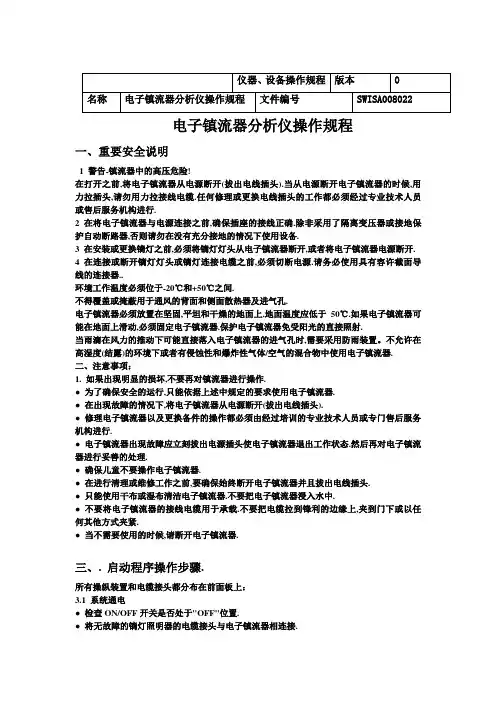
电子镇流器分析仪操作规程一、重要安全说明1 警告-镇流器中的高压危险!在打开之前,将电子镇流器从电源断开(拔出电线插头).当从电源断开电子镇流器的时候,用力拉插头,请勿用力拉接线电缆.任何修理或更换电线插头的工作都必须经过专业技术人员或售后服务机构进行.2 在将电子镇流器与电源连接之前,确保插座的接线正确.除非采用了隔离变压器或接地保护自动断路器,否则请勿在没有充分接地的情况下使用设备.3 在安装或更换镝灯之前,必须将镝灯灯头从电子镇流器断开,或者将电子镇流器电源断开.4 在连接或断开镝灯灯头或镝灯连接电缆之前,必须切断电源.请务必使用具有容许截面导线的连接器..环境工作温度必须位于-20℃和+50℃之间.不得覆盖或掩蔽用于通风的背面和侧面散热器及进气孔.电子镇流器必须放置在坚固,平坦和干燥的地面上.地面温度应低于50℃.如果电子镇流器可能在地面上滑动,必须固定电子镇流器.保护电子镇流器免受阳光的直接照射.当雨滴在风力的推动下可能直接落入电子镇流器的进气孔时,需要采用防雨装置。
不允许在高湿度(结露)的环境下或者有侵蚀性和爆炸性气体/空气的混合物中使用电子镇流器.二、注意事项:1. 如果出现明显的损坏,不要再对镇流器进行操作.● 为了确保安全的运行,只能依据上述中规定的要求使用电子镇流器.● 在出现故障的情况下,将电子镇流器从电源断开(拔出电线插头).● 修理电子镇流器以及更换备件的操作都必须由经过培训的专业技术人员或专门售后服务机构进行.● 电子镇流器出现故障应立刻拔出电源插头使电子镇流器退出工作状态.然后再对电子镇流器进行妥善的处理.● 确保儿童不要操作电子镇流器.● 在进行清理或维修工作之前,要确保始终断开电子镇流器并且拔出电线插头.● 只能使用干布或湿布清洁电子镇流器.不要把电子镇流器浸入水中.● 不要将电子镇流器的接线电缆用于承载.不要把电缆拉到锋利的边缘上,夹到门下或以任何其他方式夹紧.● 当不需要使用的时候,请断开电子镇流器.三、. 启动程序操作步骤.所有操纵装置和电缆接头都分布在前面板上:3.1 系统通电● 检查ON/OFF开关是否处于"OFF"位置.● 将无故障的镝灯照明器的电缆接头与电子镇流器相连接.● 将电子镇流器与电源相连接.● 确保主断路器处于"ON"位置.● 检查接地:如果接地正确,位于前面板上的绿色LED"PE"指示灯将点亮.如果接地不正确,从电源断开电子镇流器(拔出电线插头),然后检查电源和插座● 将ON/OFF开关设定为"ON",在电子镇流器和镝灯灯头上.大约5秒钟之后,电灯将点亮.● 当点火成功的时候,位于前面板上的黄色LED"LAMP"指示灯将点亮.四、.故障检修指南4.1 电源电压是否与镇流器所需的电压一致双重电压管理的镇流器采用了自动切换的形式.4.2 确保镇流器的瓦数符合镝灯功率!4.3 确保安装了正确的镝灯!4.4 将镇流器与电源连接,然后测试保护地(LED"PE"指示灯应处于开启的状态).4.5 重新启动系统:确保ON/OFF开关处于"OFF"的位置.. 将ON/OFF开关设为"ON",开关灯应点亮.等待大约5秒钟之后镝灯启动4.6 如果镝灯没有点亮,则安全回路可能断开-检查灯头前面的透镜门是否关闭以及安全开关是否损坏.4.7 镇流器的电源是否处于良好的状态4.8 镇流器的主断路器是否处于ON的位置4.9 如果镇流器/镝灯电缆接头/镝灯灯头无法工作,那么所有的三个装置都应视为出现故障. 不要试图使用另一个镇流器去点亮一个可能损坏的镝灯灯头-最终可能会使两个镇流器都出现故障! 检查镇流器是否处于良好的状态,采用已知的无故障的镝灯灯头和无故障的电缆接头运行镇流器.4.10 如果镇流器在运行了几分钟之后停止工作,那么可能发生了下列故障:● 镝灯自身可能出现了故障或者超过了使用寿命.● 在盛夏的条件下,可能由于过高的环境温度或者直接的阳光照射而触发了镇流器中的热断路器.● 在通风可能受到了限制情况下,在镇流器冷却下来并且导致过热的条件消除之后,镇流器可以继续使用.● 是否由于电源超过规定的极限或出现峰值或发生回落,因而镇流器断开而对自己进行保护.如果在一个发电机上运行,输出电压应分别在95-120V和195-245V之间进行调节.● 如果镇流器因为瞬时供电回落而断开,将镇流器转换到"OFF",然后再次切换到"ON".镇流器应正常启动.● 镝灯灯头的接地或镇流器电缆接头漏电也将导致保护电路的启动.采用已知的无故障镝灯灯头对镇流器进行测试.如果对电缆产生怀疑,应采用已知的无故障电缆进行更换.检查供电电源电子镇流器575/ 1200 EB的容许电源(电压)范围分别是有效电压90V至125V和190V至250V.在电子镇流器运行前或运行过程中均不得超出以上极限,否则可能引起电子镇流器发生故障或受损.此外,该电压极限90V/180V和125V/250V仅适用于短时间运行(最多0.5小时).可用普通的万用表对电源进行检查.在电源有几个半周期损耗或降低到90V以下时,电子镇流器将切换到待用状态,这时必须重新启动电子镇流器(切换开关到OFF关闭然后ON开始).仅在保持上述极限值,并且已经排除电源故障的情况下才可以运行电子镇流器.预先检查在开启电子镇流器检查前,针对镇流器的运行条件进行一定的说明.开展下列测试时,设备必须在无负载的条件下运行.第一项测试——启动程序:(电子镇流器内部接触器/继电器,保险丝测试).第二项测试——输出电压:(对电子镇流器灯连接器输出电压进行测量).根据以上两项测试的结果即可大致找出发生故障的位置以及原因.警告:电子镇流器不能离开电源单独运行.因此测量仪表必须始终保持不接地连接.电子镇流器的灯连接器插座触点可能存在线电压.必须遵守此类操作的安全规则.否则可能危及生命.第一项测试——启动程序检查启动程序时,设备应在无负载条件下运行.将电子镇流器的灯连接器上的触点A和触点B 接通以模拟灯头上的安全回路开关.把电子镇流器连接至220V的电源,如果电子镇流器正常运行,以下情况将依次出现:接通后约0.5秒时,你将听到BUCK功率控制板(EB2604)上接触器K4的微小闭合声. 约3秒钟之后,主接触器K2和K3闭合(卡嗒声),K4释放(无声). 再过1秒钟后,逆变板(EB2603)上点火接触器K1将通电约0.7秒(卡嗒声)。
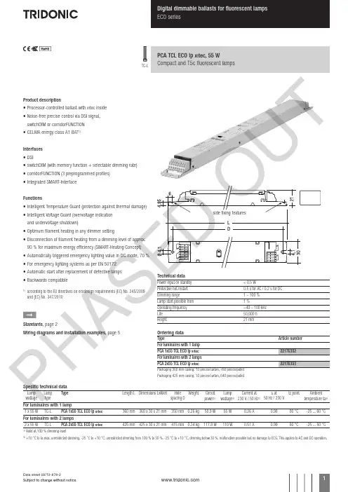
Product description• Processor-controlled ballast with y inside• Noise-free precise control via DSI signal, switchDIM or corridorFUNCTION • CELMA energy class A1 BAT 1)Interfaces • DSI• switchDIM (with memory function + selectable dimming rate)• corridorFUNCTION (3 preprogrammed profiles)• Integrated SMART-Interface Functions• Intelligent Temperature Guard (protection against thermal damage)• Intelligent Voltage Guard (overvoltage indication and undervoltage shutdown)• Optimum filament heating in any dimmer setting• Disconnection of filament heating from a dimming level of approx. 90 % for maximum energy efficiency (SMART-Heating Concept)• Automatically triggered emergency lighting value in DC mode, 70 %• For emergency lighting systems as per EN 50172• Automatic start after replacement of defective lamps• Backwards compatible1)according to the EU directives on ecodesign requirements (EC) No. 245/2009 and (EC) No. 347/2010ÈStandards , page 2Wiring diagrams and installation examples , page 5PCA TCL ECO lp Y , 55 WCompact and T5c fluorescent lampsTC-LTechnical dataPower input on standby < 0.5 WProtective hot restart 0.5 s for AC / 0.2 s for DC Dimming range 1 – 100 %Lamp start possible from 1 %Operating frequency ~40 – 100 kHz Life 50,000 hHeight21 mmOrdering dataTypeArticle number Packaging 425 mm casing: 10 pieces/carton, 640 pieces/palletSpecific technical dataLamp wattageLamp type TypeLength L Dimensions LxWxHHole spacing D Weight Circuit power 1Lamp wattage 1Current at 230 V / 50 Hz 1λ at50 Hz / 230 V tc pointAmbienttemperature ta 2For luminaires with 1 lamp1 x 55 W TC-L PCA 1x55 TCL ECO lp Y 360 mm 360 x 30 x 21 mm 350 mm 0.26 kg 58.9 W 55 W0.26 A0.9880 °C-25 ... 60 °CFor luminaires with 2 lamps2 x 55 WTC-LPCA 2x55 TCL ECO lp Y425 mm 425 x 30 x 21 mm415 mm 0.34 kg117.8 W110 W0.51 A0.9980 °C-25 ... 50 °C1Valid at 100 % dimming level2+10 °C to ta max: unrestricted dimming. -25 °C to +10 °C: unrestricted dimming from 100 % to 30 %. -25 °C to +10 °C, dimming below 30 %: malfunction possible but no damage to ECG. This applies to AC and DC operation.P HA SE U TStandards EN 55015EN 55022EN 60929EN 61000-3-2EN 61347-2-3EN 61547Suitable for emergency installations according to EN 50172Lamp starting characteristics Warm startStarting time 0.5 s with AC Starting time 0.2 s with DC Start at any dimming levelAC operation Mains voltage220–240 V 50/60 Hz198–264 V 50/60 Hz including safety tolerance (±10 %)202–254 V 50/60 Hz including performance tolerance (+6 % / -8 %)DC operation 220–240 V 0 Hz198–280 V 0 Hz certain lamp start 176–280 V 0 Hz operating rangeUse in emergency lighting installations according to EN 50172 or for emergency luminaires according to EN 61347-2-3 appendix J.Light output level in DC operation Default value is 70 %Emergency unitsThe “PCA TCL ECO lp x ” ballasts are compatible with all emergency units from Tridonic. See the table in the data sheet. Also all “5-pole” emergency units can be used. When used with other emergency units tests are necessary.Temperature rangeUnlimited dimming range from 10 °C to ta max. -25 °C to +10 °C: dimming operation from 100 % to 30 %. If dimm level goes below 30 % malfunction possible, but no electronic ballast damage. This applies to AC and DC operation.Mains currents in DC operation (at 70 % light output)TypeWattageMains current at U n = 220 V DCMains current at U n = 240 V DCPCA 1x55 TCL ECO lp X 1x55 W 0.21 A 0.19 A PCA 2x55 TCL ECO lp X2x55 W0.42 A0.38 AHarmonic distortion in the mains supply (at 230 V / 50 Hz)TypeWattage THD357911PCA 1x55 TCL ECO lp X 1x55 W 7.1 5.7 1.0 1.3 1.4 1.2PCA 2x55 TCL ECO lp X 2x55 W4.12.10.60.91.00.8Ballast lumen factor AC operation (AC-BLF) EN 60929 8.1TypeWattageAC-BLF atU = 230 V ACPCA 1x55 TCL ECO lp X 1x55 W 0.98PCA 2x55 TCL ECO lp X 2x55 W0.99The ballast lumen factor for AC operation (AC-BLF) does not alter from U n = 198 V AC to U n = 254 V AC .The ballast lumen factor for DC operation (DC-BLF) on the basis of an automatic power reduction of the ballasts (default value is 70 %) will be smaller than AC. It does not alter in the DC operating range (198–280 V DC ).P HA SE D OU T7550250100908070605040302010digital dimming value relative lighting level in %10090807060504030201001009080706050403020151054321Energy saving PCA TCL ECO lpmains power in %dimming level in %Dimming characteristics as seen by the human eyeDimming characteristics PCA TCL ECO lp1)SMART-LS II lp: article number 86458258DSI PCA TCL ECO lp Xswitch DIM PCA TCL ECO lpXDimmingDimming curve is adapted to the eye sensitiveness.Dimming range 1 % to 100 %Digital control with DSI signal: 8 bit Manchester Code Speed 1 % to 100 % in 1.4 sControl input (D1, D2)Digital DSI signal, push-to-make switch (switchDIM) or a motion detector (corridorFUNCTION) can be wired on the same terminals (D1 and D2).Digital signal DSIThe control input is non-polar and protected against accidental connection with a mains voltage up to264 V. The control signal is not SELV. Control cable has to be installed in accordance to the requirements of low voltage installations.Different functions depending on each module.SMART interfaceAn additional interface for the direct connection of the SMART-LS II lp 1) light sensor or corridorFUNCTION Plugs.Application and functionallity see corridorFUNCTION user manual.SMART-LS II lp 1) light sensor operating mode:The sensor registers actual ambient light and main-tains the individually defined lux level.After every mains reset the SMART interface auto-matically checks for an installed sensor. With the sensor installed the PCA TCL ECO lp x automati-cally runs in the constant lux level mode.ON/OFF switch via mains, switchDIM or DSI signal.DSI signal = 0 switches off,DSI signal ≥ 1 switches on.With switchDIM signals it is possible to change the controlled light level temporarily.Temporarily means that after a switching cycle OFF/ON command the ballast will start at the preset value determined by the SMART-LS II lp. The installa-tion of the two wire bus is according to the appropriate low voltage regulations.switchDIMIntegrated switchDIM function allows a direct connection of a push to make switch for dimming and switching.Brief push (< 0.6 s) switches ballast ON and OFF. The ballasts switch-ON at light level set at switch-OFF.When the push to make switch is held, PCA ballasts are dimmed. After repush the PCA is dimmed in the opposite direction.The switchDIM fade time is set to 3 s from min. to max. in the factory settings. With a 20 s push to the push to make switch this fade time can be changed to 6 s. In this instance the switchDIM application will be synchronized to 50 % light level after 10 s and after 20 s the light level rises to 100 % with the new fade time.At every synchronizsation (10 s keystroke) the device will reset to 3 s (factory setting)In installations with PCAs with different dimming levels or opposite dimming directions (e.g. after a system extension), all PCAs can be synchronized to 50 % dimming level by a 10 s push.Use of push to make switch with indicator lamp is not permitted.Deactivation: If the corridorFUNCTION is wrongly activated in a switchDIM system (for example a switch is used instead of pushbutton), there is the option of installing a pushbutton and deactivating the corridorFUNCTION mode by five short pushes of the button within three seconds.switchDIM and corridorFUNCTION are very simple tools for controlling ballasts with conventional momentary-action switches or motion sensors.To ensure correct operation a sinusoidal mains voltage with a frequency of 50 Hz or 60 Hz is required at the control input.Special attention must be paid to achieving clear zero crossings.Serious mains faults may impair the operation of switchDIM and corridorFUNCTION.Backwards compatibilityWith a simple key combination a PCA TCL ECO lp x can be reset as a normal PCA ECO from the previous generation. Synchronisation simply has to take place three times within one minute (3 x 10 s). To activate the “x ” settings again, synchronisation has to take place four times within one minute.Dimmable ballasts from Tridonic have to be earthed.Loading of automatic circuit breakersAutomatic circuit breaker type C10C13C16C20B10B13B16B20Installation Ø1.5 mm 21.5 mm 21.5 mm 22.5 mm 21.5 mm 21.5 mm 21.5 mm 22.5 mm 2PCA 1x55 TCL ECO lp X 2234485211172426PCA 2x55 TCL ECO lp X12162226681113Continuous operation: to calculate the protective saftey switch see main current, page 1P HA SE D OWiring adviceThe lead length is dependent on the capacitance of the cable.With standard solid wire 0.5/0.75 mm² the capacitance of the lead is 30–80 pF/m. This value is influenced by the way the wiring is made. Lamp connection should be made with symmetrical wiring.Hot leads (9, 10, 15, 16) and cold leads (11, 12, 13, 14) should be separated as much as possible.When using two or more dimmable ballasts in one luminaire with separate dimming controls, the lamp leads must be kept separate.Dimmable ballasts from Tridonic have to be earthed.Installation instructionsWiring type and cross sectionThe wiring can be solid cable with a cross section of 0.5 to 0.75 mm² for push terminal and 0.5 mm² for IDC terminal. For the push-wire connection you have to strip the insulation (8–9 mm).Loosen wire through twisting and pullingwire preparation:Intelligent Temperature GuardThe intelligent temperature guard protects the PCA TCL ECO lp x from thermal overheating by reducing the output power or switching off in case of operation above the thermal limits of the luminaire or ballast. Depending on the luminaire design, the ITG operates at about 5 to 10 °C above Tc temperature.Intelligent Voltage GuardIntelligent Voltage Guard is the name of the new elec-tronic monitor from Tridonic. This innov ative feature of the PCA family of control gear fromTridonic immediately shows if the mains voltage rises above certain thresholds. Measures can then be taken quickly to prevent damage to the control gear.• If the mains voltage rises above approx. 305 V (voltage depends on the ballast type), the lamp starts flashing on and off.• This signal “demands” disconnection of the power supply to the lighting system.corridorFUNCTIONActivation: To activate the corridorFUNCTION a voltage of 230 V simply has to be applied for five minutes at D1, D2. The unit will then switch automatically to the corridorFUNCTION.Deactivation: If the corridorFUNCTION is wrongly activated in a switchDIM system (for example a switch is used instead of pushbutton), there is the option of installing a pushbutton and deactivating the corridorFUNCTION mode by five short pushes of the button within three seconds.The corridorFUNCTION V2 offers the added benefit of a second and third preprogrammed profile, which can be activated by the corridorFUNCTION plugs.Application and functionallity of profiles see user manual.Operating voltageTypeWattage U out PCA 1x55 TCL ECO lp X 1x55 W 250 V PCA 2x55 TCL ECO lp X2x55 W350 VBallastTerminalMaximum capacitance allowed TypeColdHot Cold Hot PCA 1xx TCL ECO lp X11, 129, 10200 pF 100 pF PCA 2xx TCL ECO lp X11, 12, 13, 149, 10, 15, 16200 pF100 pFP HA SE D OU TRFI• Connection to the lamps of the hot leads must be kept as short as possible• Mains leads should be kept apart from lamp leads (ideally 5–10 cm distance)• Do not run mains leads adjacent to the electronic ballast • Twist the lamp leads• Keep the distance of lamp leads from the metal work as large as possible• Mains wiring to be twisted when through wiring • Keep the mains leads inside the luminaire as short as possibleGeneral adviseElectronic ballasts are virtually noise free.Magnetic fields generated during the ignition cycle can cause some background noise but only for a few milliseconds.For further technical information please visit PCA TCL ECO lp X 1x36–58 WPCA TCL ECO lp X 2x36–58 WDimmable ballasts from Tridonic have to be earthed.* * * leads 9, 10: keep wires short, max. 1.0 mleads 11, 12: max. 2.0 m; ballast must be earthed * * digital signal (DSI) or switchDIM* ** leads 9, 10, 15, 16: keep wires short, max. 1.0 mleads 11, 12, 13, 14: max. 2.0 m; ballast must be earthed* * digital signal (DSI) or switchDIMOperation on DC voltageOur ballasts are construed to operate DC voltage and pulsed DC voltage.To operate ballasts with pulsed DC voltage the polarity is absolute mandatory.Isolation and electric strength testing of luminairesElectronic devices can be damaged by high voltage. This has to be considered during the routine testing of the luminaires in production.According to IEC 60598-1 Annex Q (informative only!) or ENEC 303-Annex A, each luminaire should be sub-mitted to an isolation test with 500 V DC for 1 second. This test voltage should be connected between the interconnected phase and neutral terminals and the earth terminal.The isolation resistance must be at least 2 MΩ.As an alternative, IEC 60598-1 Annex Q describes a test of the electrical strength with 1500 V AC (or 1.414 x 1500 V DC ). To avoid damage to the electronic devices this test must not be conducted.P HA SU。
BERSN铂胜 高品质电子镇流器使用说明书
一、产品描述:
1、用途
本产品是与相应功率的气体放电灯(包括金卤灯和高压钠灯及低压钠灯等)配套使用电子镇流器,可以广泛应用于道路、广场、商场,车站、码头、工厂等场所。
2、本品具有如下特点:
z高用电质量,省电节能。
z降低初装费用,节约运行开支。
z灯光稳定,提高照明质量。
z电压适应范围宽,适合我国国情。
z灯泡启动快,延长使用寿命。
z多项保护功能,安全可靠。
z体积小、重量轻、安装简单方便。
3、与电感镇流器相比具有如下优势:
z克服了电感镇流器多消耗的20%以上的有功电能。
z克服了电感镇流器因功率因数低带来的60%以上的无功损耗(即线损)。
z克服了电感镇流器由于频闪引起的灯光不稳定给工作中眼部带来的刺激、疲劳
z克服了电感镇流器产生的电磁传导干扰对电网环境的污染。
z克服了电感镇流器产生的交流嗡声对环境的污染。
z克服了有些触发器脉冲高压过高对灯泡及镇流器寿命的危害。
z克服了电感镇流器启动电流大于工作电流使灯泡寿命缩短的弊端。
z克服了灯开路,灯短路易损坏镇流器的弊病。
z克服了电感镇流器安装复杂,工作量过高的麻烦。
z克服了电感镇流器因功率因数低工作电流大。
z安装时使用线径要比使用本品大3-4倍造成的工程造价过高的负担。
电子镇流器安装使用说明书及注意事项
B ERSN铂胜电子镇流器的安装与使用必须由具有相应资质的技术人员按相应标准进行
操作,并请于安装前详细阅读《使用说明书》以及镇流器外壳上的安装示例。
对于本司所有产品在客户进行私自拆启之后本公司所有保修、保换自动失效,对此种情况下的任何机器故障及其引起的损失本公司概不负责。
一、请依照产品参数表确认本镇流器输入电源电压范围,请注意交流或直流产品的使用区别。
二、安装示意图
请注意一定按下图接线方式进行安装,并确保各点的可靠连接。
以出线朝下竖直安装为宜,并请依照产品参数表确认镇流器输入电源范围。
□ 交流供电系列电子镇流器接线
不分极性,输入端两根线接电源,输出端两根线接灯管,并将地线可靠接地,可使用0.5~0.75平方毫米塑料绞线(应同时满足安装规范要求)
□ 直流供电系列电子镇流器接线
请注意正负极性,输入端红线接正极,黑线接负极(如有接反请即更换保险丝),输出端两根接灯管,并将地线可靠接地。
三、安装注意事项:
1、镇流器自身有触发功能,不能再配接触发器或使用内部有触发器的灯泡。
本镇流器工作
频率为高频,所以在输入、输出端不可接任何测试设备,否则将会永久烧毁测试设备及镇流器。
即镇流器的输出端只能连接光源,不能在输出端加任何测试仪器或设备(如开关或任何其它器件)。
输入线宜串入约为额定电流3-5倍的保险或自动开关。
输出线间及对地之间,启动时有上千伏电压,应保持良好的绝缘。
同时在安装维护时务必请切断电源.
2、镇流器到灯之间的连接请使用耐压>600V且符合安规要求的电源线,长度勿超过5m,引线
长度大于3m时,请不要使用并绕的电源线(并绕线电容过大可能影响灯泡的正常燃点)。
3、为保证光源达到最佳工作状态,使用的灯泡类型和功率,应与镇流器相匹配.
4、额定电压为110V60Hz的镇流器工作电压范围为:90V~130V;额定电压为220V50Hz的镇流
器工作电压范围为:170V~260V;直流12V产品工作电压范围为:10V~14V;直流24V产品工作电压范围为:20V~24V.请勿尝试在超过工作电压范围的情况下使用镇流器.
5、铂胜电子镇流器的外壳,具有散热功能,周围应留有适当的散热空间,外壳最高允许温
度80℃,储存温度-40- 90℃。
镇流器使用环境温度为:-25~50℃,在超出此温度范围内使用镇流器可能出现意想不到的结果,如灯泡不能正常启动、镇流器寿命缩短等.
6、因配套高压钠灯或金卤灯等气体放电灯特性所致,点燃的灯泡在关闭或熄灭后,必须等
灯泡足够冷却,才能再次点亮,视不同规格的灯泡,钠灯可能需等待1~2分钟,金卤灯可能需等待5~15分钟,镇流器将自动完成此过程的控制,无需人工干预;
四、电子镇流器出现的可能故障及解决方法
1.请一定注意按所示故障处理方法进行严格检查及操作以避免不必要的损失。
2.请注意无论在何种情况下均不要使用任何仪器仪表对镇流器的输出端进行测量。
3.请按照所示步骤进行以逐一排除故障。
对于任一步骤所存在的问题请及时更正改良。
4.请注意在以下任何步骤中如需要重新通电启动电镇时均要考虑到是否有3-5分种的时间
间隔以确保光源的冷却及电镇的重启。
5.请注意如经下述步骤认定镇流器有损坏,不能自行打开,应到供应商处更换或由供应商
返厂保修。
否则将失去保修资格。
可能故障及解决方法示意图:
故 障 解决方法
1、断开所有连接,如镇流器有保险丝,请检查保险丝。
2、更换同功率灯管进行测试。
如新灯管亮则表明灯管有问题,需要更
换灯管;
3、断开所有连接。
检查整个输入线路是否有接触不良及是否有额定的电压输入,电压范围是否正常;
4、检查镇流器输出端是否与灯座或灯头接触不良,检查灯头或灯座有无短路或接触不良(对镇流器输出端绝不可以加任何仪器仪表进行测试);
4、上述步骤完成后如问题仍未解决,请将所有电路连接好,通电,并
保持通电3-5分钟,看镇流器能否重新启动及是否启用了自动保护功能;
安装完毕后灯泡不能点亮或点亮后马上熄灭或灯光闪烁 5、用一只正常工作中的镇流器来更换被认为有问题的镇流器。
如
灯亮则表明原电子镇流器损坏。
如灯仍不亮请重复以上步骤进行检查;
注意 注意在以上过程中任何一次通电连接后均应间隔3-5分钟后才能再次通电,或通电后保持3-5分钟以让电子镇流器自动重启
1、检测环境温度,如环境温度过高,镇流器将处于超温自我保护状态;(镇流器安装环境温度超过70℃时可能发生)
2、更换灯泡,看是否可正常工作;
灯泡在长时间工作后熄灭 3、用一只正常工作的镇流器来代替并观察问题是否发生。
如问题未解
决请重复上述步骤。
如新电镇工作正常可判断为原电镇损坏
直流系列产品请特别注意:
当认为直流电子镇流器出现故障时请按上述示意图进行操作以排除故障。
同时请尝试以下方式:
a) 检查蓄电池输出电压是否稳定,电池电量是否充足。
b) 检查控制器输出电压是稳定,是否符合电子镇流器的工作电压要求。
c) 必要时可用蓄电池直接连接电子镇流器及灯管以排除其它器件出问题的可能性。
d) 应用低压钠灯光源时要注意其灯座(灯头)的可靠性。
何疑问请及时与铂胜公司技术部门进行沟通。
电话:0086-755-29890606
电邮:bersn@
网址:
深圳市铂胜光电有限公司。