MBS1000使用说明书
- 格式:pdf
- 大小:1.16 MB
- 文档页数:7

1. 产品简介MBS(Methyl methacrylate-Butadiene-Styrene)树脂是甲基丙烯酸甲酯(M),丁二烯(B)及苯乙烯(S)的三元共聚物,它具有典型的核- 壳结构。
由于其溶度参数(19.2~19.4 J1/2?ml1/2 )与PVC(19.4~19.8 J1/2?ml1/2)相近,故两者的热力学相容性好,表现为PVC 在室温或低温下具有很高的抗冲击强度。
并且由于它与PVC 折光指数相近(PVC 为1.530~1.538,MBS 为1.528~1.540),故当两者共混熔融以后,容易达到均一的折射率。
又由于MBS 树脂粒子直径为0.1~0.25μm,比可见光波长0.4~0.7μm 还小,因此用MBS 做PVC 的抗冲改性剂不会影响PVC 的透明性。
所以MBS 是PVC 制取透明制品的最佳材料。
另一方面,由于其与PVC 相容性好,在室温或低温下具有很高的抗冲击性,故也适用于非透明性的各种制品。
据资料介绍,当PVC 中加入5%~10%的MBS 树脂时,可使其制品的抗冲击强度提高4~15 倍,同时还可以改善制品的耐寒性和加工流动性。
因此,MBS 作为PVC 抗冲改性剂得到了广泛应用。
此外,它还具有良好的着色性,可用于制作盛装容器、管材、板材、室内装饰板和软质制品等。
但因其含有不饱和结构的丁二烯、易受氧和紫外线的作用而老化,故耐候性差,不适用于制作室外长期使用的制品。
2. 产品牌号及性能、用途2.1 日本钟渊公司产品牌号及性能2.2 日本吴羽公司产品牌号及性能2.3 日本三菱人造丝的产品性能及用途2.4 罗门-哈斯公司产品及性能2.5 齐鲁石化公司研究院MBS 产品特性及用途2.6 浙江龙化塑料助剂有限公司的产品性能及用作为PVC 最主要的抗冲改性剂之一,MBS 树脂既可以在增韧的同时,最大限度保持PVC 的透明性,同时与其它抗冲改性剂相比,在同等加入量情况下,还可以更大幅度地提升制品的韧性,因而广泛用于PVC 与PBT/PC 等工程塑料的加工应用过程中处于玻璃态的材料(如PVC 树脂)在应力作用下引起材料破坏的原因,是材料发生强迫高弹形变。
目录1测量原理――――――――――――――――――――――――――――2 2系统组成――――――――――――――――――――――――――――2 2.1传感器―――――――――――――――――――――――――――――2 2.2氧分析仪―――――――――――――――――――――――――――—3 2.3仪器面板、拨码开关及主板发光二极管功能――――――――――――—4 3传感器和氧分析仪的安装――――――――――――――――――――—6 4 氧分析仪工作状态―――――――――――――――――――――――—9 4.1 实时测量显示状态―――――――――――――――――――――――—9 4.2 显示系统工作参数状态――――――――――――――――――――――10 4.3 编程状态――――――――――――――――――――――――――――11 5 系统校准――――――――――――――――――――――――――――14 5.1 两点校准――――――――――――――――――――――――――――14 5.1.1 标准方法――――――――――――――――――――――――――――14 5.1.2 简便方法――――――――――――――――――――――――――――15 5.1.3 标准气体――――――――――――――――――――――――――――16 5.2 单点标准――――――――――――――――――――――――――――16 5.2.1 标准方法――――――――――――――――――――――――――――16 5.2.2 简便方法――――――――――――――――――――――――――――186 常规检查和维护―――――――――――――――――――――――――187 故障诊断与排除―――――――――――――――――――――――――198 氧化锆氧分析仪技术数据―――――――――――――――――――――22 8.1 氧分析仪――――――――――――――――――――――――――――22 8.2 传感器―――――――――――――――――――――――――――――23 9 1230/1000氧化锆氧分析仪故障速查表―――――――――――――――24附录1 氧化锆传感器氧浓差电势——氧浓度对照表附录2 K型热电偶分度表附录3 实验室检验校准步骤附录4 氧化锆探头搬运储存安装注意事项附录5 1230/1000氧化锆氧分析仪系统组成示意图附录6 1000型氧分析仪安装尺寸图附录7 1231氧化锆探头保护套管尺寸图附录8 1230/1000氧化锆氧分析仪接线图注意:1)仪器和探头带电时,除面板操作外,不得进行其他任何操作,以免触电危及生命!2)探头内锆管是易脆品,务必轻拿轻放,不得与包括地面在内的任何物体碰撞,以免锆管断裂、破碎!3)仪器的软件和本说明书受中华人民共和国著作权法保护,未经著作权人同意,任何人不得影印、复制、摘录、修改、传播其中内容,否则将承担相应的法律责任!1测量原理Ronyin1000型氧化锆氧分析仪,主要用于测量燃烧过程中烟气的含氧浓度,同样也适用于非燃烧气体氧浓度测量。

SPECIFICATIONS Detector T ype: GermaniumWavelength:850nm, 1300nm & 1550nm typicalMeasurement Range:+5dBm to -60dBmMeasurement Accuracy:±0.3dBm (±5%) at -23dBm and +20ºC ±3ºC Measurement Resolution: 0.1dBmdBm and dBrel:YesBatteries:2 x AA Alkaline Cells (NiMh on NiCad can be used) Battery Consumption:20mA nominalPower Input:Can operate and charge internal batteries using optional chargerOptical Connector:ST, FC or SC connector adaptors availableCase Dimensions:160mm x 83mm x 30mm InstrumentWeight:230g with battery Operational Temperature: -15ºC to +50ºC (+5ºF to+122ºF)Operational Humidity: 95% at +40ºC (+104ºF) Storage Temperature:-20ºC to +70ºC (-4ºF to+158ºF)MPM1000Fiber Optic Power MeterDESCRIPTIONThe MPM1000 is an accurate optical power meter that can be used for optical loss testing of fibre optic cables. It has been pre-calibrated for absolute power levels with reference to 1mW (dBm) for 850nm, 1300nm and1550 nm wavelengths using multi-mode cables. However, it can also be used in relative power mode and can therefore also be used on single-mode cables. TheMPM1000 is accurate to ±5% (±0.3dBm) and has a wide dynamic range of +5dBm to -60dBm with a resolution of 0.1dBm.It is particularly suitable for the testing of LAN's, FDDI, and other multimode links whether inside or outside a building.Although the MPM1000's main use is in fibre optic cable attenuation testing, other applications include fibre continuity testing, connector testing, and patch lead testing.Battery status warning indicates low battery condition. An optical battery charger is available when using rechargeable batteries.s850, 1300 & 1550nm Germanium Detector s Wide Dynamic Ranges dBm and dBrel (relative) measurement modess Automatic Power Downs Power Down override during dBrel measurementss Exceptional battery lifes Ruggedised waterproof housing to IP54s 3 Year manufacturers warrantyUKArchcliffe Road Dover CT17 9EN EnglandT +44 (0) 1304 502101 F +44 (0) 1304 207342UNITED STATES4271 Bronze WayDallas TX 75237-1088 USAT 800 723 2861 (USA only)T +1 214 333 3201F +1 214 331 7399OTHER TECHNICAL SALES OFFICESNorristown USA, Toronto CANADA,Mumbai INDIA, Trappes FRANCE,Sydney AUSTRALIA, Madrid SPAINand the Kingdom of BAHRAIN.Registered to ISO 9001:2000 Reg no. Q 09290Registered to ISO 14001 Reg no. EMS 61597MPM1000_DS_en_V11Megger is a registered trademark。


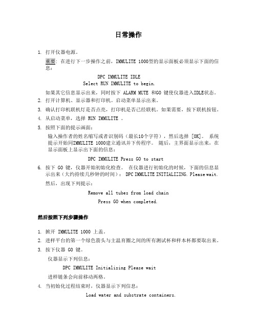
日常操作1. 打开仪器电源。
在进行下一步操作之前,IMMULITE 1000型的显示面板必须显示下面的信DPC IMMULITE IDLESelect RUN IMMULITE to begin.如果其它信息显示出来,同时按下 ALARM MUTE 和GO 键使仪器进入IDLE状态。
2. 打开计算机、显示器和打印机。
启动菜单显示出来。
3. 确认打印机联机灯是否点亮,打印机是否已经联机。
如果需要,按下联机按钮。
4. 从启动菜单,选择 RUN IMMULITE 。
5. 按照下面的提示画面:输入操作者的姓名缩写或者识别码(最长10个字符),然后选择 [OK]。
系统提示开始同IMMULITE 1000建立通讯并下传程序。
随后,主界面显示出来,在显示面板上显示出下面的信息:DPC IMMULITE Press GO to start6. 按下 GO 键,仪器开始初始化检查。
在仪器进行初始化的时候,下面的信息显示出来(大约持续几秒钟的时间): DPC IMMULITE INITIALIZING. Please wait.然后,出现下列提示:Remove all tubes from load chainPress GO when completed.然后按照下列步骤操作1. 掀开 IMMULITE 1000 上盖。
2. 进样平台的第一个绿色箭头与主温育圈之间的所有测试杯和样本杯都要取出来。
3. 按下仪器 GO 键。
仪器显示下列信息:DPC IMMULITE Initializing Please wait进样链条会向前移动两格。
4. 当初始化过程结束时,仪器显示下列信息:Load water and substrate containers.Empty waste container and press GO.5. 按下显示面板的GO键仪器显示下列信息:IMMULITE is priming the syringes. Please wait.IMMULITE 1000 自动初始化注射器一次,然后显示下列信息:Prime the syringes, substrate and water.Press GO when done.6. 检查注射器下面的手旋螺丝和注射器玻璃管是否拧紧。
Model MBS1000ADesktopPaging MicrophoneDESCRIPTIONThe Bogen Model MBS1000A is a dual-impedance,uni-directional,dynamic desktop microphone with a rubberized finish for all industri-al and commercial public address and paging applications.TheMBS1000A has a bottom-mounted slide switch for low- or high-impedance selection.The wide band frequency response is smooth andpeak free,thereby providing a natural,highly-intelligible sound.The microphone output provides a normally open switch closure pairthat can be used to operate external equipment.When the micro-phone is activated using either the push-to-talk or lift-to-talk functions,the provided contact closes.The push-to-talk actuator bar includes alocking feature to allow the mic to remain active for extended periods.The lift-to-talk feature can be enabled or disabled using a bottom-mounted selector switch.Four molded,non-skid,non-marring,and permanently resilient "feet"are located under the cast base.SPECIFICA TIONSElement:DynamicPolar Pattern:Uni-directionalFrequency Response:45 to 15,000 HzOutput:Hi-Z:-52 dB (0 dB = 1 volt/microbar)Lo-Z:-72 dB (0 dB = 1 volt/microbar)Impedance:Hi-Z:50,000 ohms,matches 50,000 ohmsor greaterLo-Z:500 ohms,matches 125 to 1000 ohmsSwitch:Push-to-talk and push-to-lockCable:7-feet of four-conductor,two-shielded cable(mic leads shielded,contacts not shielded)Dimensions:4-3/8" W x 9-3/8" H x 5-7/8" DProduct Weight:1lb.Finish:Black rubberized finish with die cast baseIMPEDANCEThe Bogen Model MBS1000A is a dual-impedance microphone.Thehigh-impedance position is 50,000 ohms unbalanced and the low-impedance is 500 ohms balanced.The low-impedance position is rec-ommended for long cable length requirements.Cable lengths of 100feet or more can be used in this position without loss of level or dete-rioration of high frequency response.Printed in Korea.0302© 2003 Bogen Communications,Inc.54-5901-02ASpecifications subject to change without notice.50 Spring Street,Ramsey,NJ 07446,U.S.A.201-934-8500;Fax:201-934-9832E-mail:**************/Web Site:SELECTORS AND SWITCHESCABLE END CONNECTIONS HI IMPEDANCE:Connect the red lead to an unbalanced mic input,the black lead and shield to ground,and the white and green to external equipment (if applicable).LO IMPEDANCE:Connect cable leads,red and black,to a balanced mic input;shield to ground;and white and green to external equipment (if applicable)PHASINGPositive pressure (movement of diaphragm inward) will generate a positive voltage on the red cable lead with respect to the black lead.CABLE CONNECTIONSFREQUENCY RESPONSE GRAPH。
USER MANUAL MODEL 1000 and 1000S Ultra Miniature Asynchronous Short Range Modems SALES OFFICE (301) 975-1000TECHNICAL SUPPORT (301) 975-1007Part #07M1000-C Doc. #023021U,Rev. D Revised 1/22/08C E R T I F I E D An ISO-9001Certified Company1.0 WARRANTY INFORMATIONPatton Electronics warrants all Model 1000 components to be free from defects, and will—at our option—repair or replace the product should it fail within one year from the first date of shipment.This warranty is limited to defects in workmanship or materials, and does not cover customer damage, abuse or unauthorized modification. If this product fails or does not perform as warranted, your sole recourse shall be repair or replacement as described above. Under no condition shall Patton Electronics be liable for any damages incurred by the use of this product. These damages include, but are not limited to, the following: lost profits, lost savings and incidental or consequential damages arising from the use of or inability to use this product. Patton Electronics specifically disclaims all other warranties, expressed or implied, and the installation or use of this product shall be deemed an acceptance of these terms by the user.1.1 RADIO AND TV INTERFERENCEThe Model 1000 generates and uses radio frequency energy, and if not installed and used properly—that is, in strict accordance with the manufacturer's instructions—may cause interference to radio and television reception. The Model 1000 has been tested and found to comply with the limits for a Class A computing device in accordance with the specifications in Subpart J of Part 15 of FCC rules, which are designed to provide reasonable protection from such interference in a commercial installation. However, there is no guarantee that interference will not occur in a particular installation. If the Model 1000 does cause interference to radio or television reception, which can be determined by turning the power off or disconnecting the RS-232 interface, the user is encouraged to try to correct the interference by one of the following measures: moving the computing equipment away from the receiver, re-orienting the receiving antenna and/or plugging the receiving equipment into a different AC outlet (such that the computing equipment and receiver are on different branches).1.2 CE NOTICEThe CE symbol on your Patton Electronics equipment indicates that it is in compliance with the Electromagnetic Compatibility (EMC) directive and the Low Voltage Directive (LVD) of the Union European (EU). A Certificate of Compliance is available by contacting Patton Technical Support.11.2 SERVICEAll warranty and non-warranty repairs must be returned freight prepaid and insured to Patton Electronics. All returns must have a Return Materials Authorization number on the outside of the shipping container. This number may be obtained from Patton Electronics Technical Service at (301) 975-1007; : or,******************.NOTE:Packages received without an RMA number will not be accepted.Patton Electronics' technical staff is also available to answer any questions that might arise concerning the installation or use of your Model 1000. Technical Service hours: 8AM to 5PM EST, Monday through Friday.22.0 GENERAL INFORMATIONThank you for your purchase of this Patton Electronics product. This product has been thoroughly inspected and tested and is warranted for One Year parts and labor. If any questions or problems arise during installation or use of this product, please do not hesitate to contact Patton Electronics Technical Support at (301) 975-1007.2.1 FEATURES• New design uses Surface Mount Technology• Full duplex• Data rates to 19.2 Kbps• Range to 17 miles (27.2 km)• No AC power required• External DCE/DTE switch• Uses modular plugs (RJ-11 or RJ-45) or terminal posts fortwisted pair connections• Very thin case (.75") for closely spaced computer ports• New snap-together, pop-open case• Surge protected (Model 1000S only)• Made in USA2.2 DESCRIPTIONThe Model 1000 Asynchronous Short Range Modem uses the latest surface mount technology to attain high quality short range modem performance in a low profile package. The unit operates full duplex at data rates to 19.2 Kbps over 2 twisted pair. Requiring no AC power or batteries, the Model 1000 supports distances to 17 miles (27.2km).With an externally accessible DCE/DTE switch, the Model 1000 allows easy connection to any device without opening the unit. Three enclosure options allow terminations to be via RJ-11, RJ-45 or terminal blocks. A unique strain relief prevents thin twisted pairs from breaking or pulling loose.The Model 1000S is a surge protected version of the Model 1000 that uses the latest in bi-directional, clamping, transient suppressors to protect itself and connected equipment against harmful transient discharges. For surge handling capability, the Model 1000S is compliant with IEC 801.5 level 2, 1kV.34.0 INSTALLATIONOnce you have properly configured the DTE/DCE switch, you are ready to connect the Model 1000 to your system. This section tells you how to properly connect the Model 1000 to the twisted pair and RS-232 interfaces, and how to operate the Model 1000.4.1 CONNECTION TO THE TWISTED PAIR INTERFACEThe Model 1000 supports data-only communication between two RS-232 devices at distances to 17 miles (27.2 km) and data rates to 19.2 Kbps. There are two essential requirements for installation:1. These units work in pairs. Therefore, you must have one Model1000 at each end of a two twisted pair interface.2. To function properly, the Model 1000 needs two twisted pair ofmetallic wire. The pairs must be unconditioned, dry metallic wire, between 19 and 26 AWG (.4mm to .9mm) (the higher numbergauges may limit distance). Standard dial-up telephone circuits, or leased circuits that run through signal equalization equipment are not acceptable.For your convenience, the Model 1000 is available with three different twisted pair interfaces: RJ-11 jack, RJ-45 jack and terminal blocks with strain relief.4.1.1 TWISTED PAIR CONNECTION USING RJ-11 OR RJ-45The RJ-11 and RJ-45 connectors on the Model 1000's twisted pair interface are pre-wired for a standard TELCO wiring environment (see Figure 3). The table on the following page shows the signal/pinrelationships.610. TIP the top half of the case as necessary to place it over the strain relief assembly (see Figure 11, below). Do not snap the case together yet.11. Insert one captive screw through a saddle washer and then insert the entire piece through the hole in the DB-25 end of the case. Snap that side of the case closed. Repeat the process for the other side. This completes cable installation.4.2 CONNECTION TO THE RS-232 INTERFACEOnce you have configured the Model 1000 for DTE or DCE and connected the twisted pair wires correctly, simply plug the Model 1000 directly into the DB-25 port of the RS-232 device. After doing so, remember to insert and tighten the two captive connector screws.(Note: If you must use a cable to connect the Model 1000 to the RS-232, make sure it is a straight through cable of the shortest possible length—we recommend 6 feet or less).4.3 OPERATING THE MODEL 1000Once the Model 1000 is properly installed, it should operate transparently—as if it were a standard cable connection. Operating power is derived from the RS-232 data and control signals; there is no"ON/OFF" switch.Dear Valued Customer,Thank you for purchasing Patton Electronics products! We do appreciate your business. I trust that you find this user manual helpful.We manufacture one of the widest selections of data communications products in the world including CSU/DSU's, network termination units, powered and self-powered short range modems, fiber optic modems, interface converters, baluns, electronic data switches, data-line surge protectors, multiplexers, transceivers, hubs, print servers and much more. We produce these products at our Gaithersburg, MD, USA, facility, and can custom manufacture products for your unique needs.We would like to hear from you. Please contact us in any of the following ways to tell us how you like this product and how we can meet your product needs today and in the future.Web: Sales E-mail: ****************Support E-mail: ******************Phone - Sales (301) 975-1000Phone - Support (301) 975-1007Fax: (301) 869-9293Mail: Patton Electronics Company7622 Rickenbacker DriveGaithersburg, MD 20879 USAWe are committed to a quality product at a quality price. Patton Electronics is ISO 9001 certified. We meet and exceed the highest standards in the industry (CE, UL, etc.).It is our business to serve you. If you are not satisfied with any aspect of this product or the service provided from Patton Electronics or its distributors, please let us know.Thank you.Burton A.PattonVice PresidentP.S. Please tell us where you purchased this product:__________________________________________________________________________________________________________________ _________________________________________________________ _________________________________________________________ _________________________________________________________ _________________________________________________________。
Q/GCL-WF 江苏协鑫硅材料科技发展有限公司企业标准Q/GCL-WF 40422—2010a NTC(MBS1000)开方机生产作业指导书2010-4-29发布 2010-4-29实施江苏协鑫硅材料科技发展有限公司发布※※修订履历※※2010-4-29发布 2010-4-29实施江苏协鑫硅材料科技发展有限公司发布受控状态:受控目录1 范围.............................................................................................................................................. - 1 -2 引用标准...................................................................................................................................... - 1 -3 定义............................................................................................................................................ - 1 -4 工作职责.................................................................................................................................... - 1 -5 操作程序.................................................................................................................................... - 2 -6 其它事项.................................................................................................................................... - 4 -7 检查与考核................................................................................................................................ - 4 -8 表格与记录.................................................................................................................................. - 4 -9 附录............................................................................................................................................ - 4 -附加说明.......................................................................................................................................... - 5 - 江苏协鑫硅材料科技发展有限公司2010-4-29发布 2010-4-29实施Q/GCL-WF江苏协鑫硅材料科技发展有限公司企业标准Q/GCL-WF 40422-2010a NTC(MBS1000)开方机生产作业指导书1范围本标准规定了江苏协鑫硅材料科技发展有限公司(以下简称“协鑫硅材料公司”) NTC (MBS1000)开方机操作的要求、程序、内容和表达形式等。