H5CX-数字定时器说明书
- 格式:pdf
- 大小:3.06 MB
- 文档页数:30
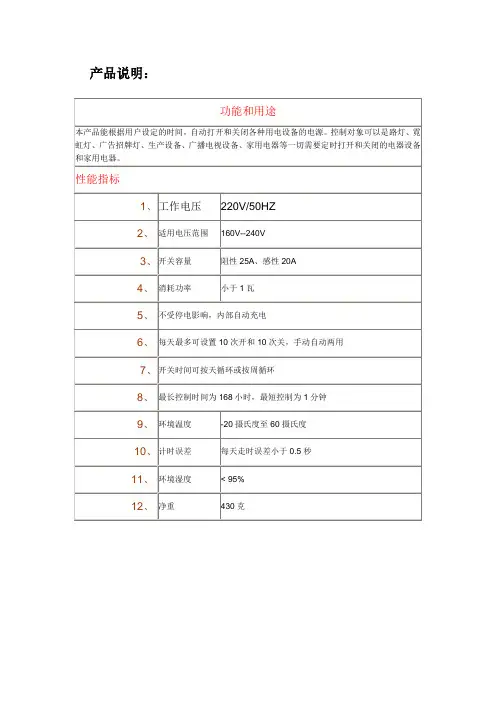
产品说明:使用方法:用户使用时请先认清产品面板上的按键与显示,一边阅读,一边操作液晶屏幕显示说明面板按键1、调时钟(一般在出厂时已调好,如果需要重新调整,您可以按如下方法)调整星期先按住“时钟”键不放,同时再按“校星期”则在液晶显示屏上循环显示星期一至星期日,调整正确后释放。
调整时、调整分先按住"时钟"键不放,同时再按“校时”则调整时,同时再按“校分”则调整分钟。
2、设定第一次开按一下“定时”键,液晶显示屏出现下图所示,定时组编号为1,且显示定时“开”,再按“校时”键、“校分”键,来设定第一次开的时间。
3、设定第一次关连续按“定时”键,您可以发现定时组编号按1开、1关、2开、2关、3开、3关、4开、4关--------9开、9关、10开、10关共10组开关循环显示。
选择1关则表示设置第一次关。
再按“校时”键、“校分”键,来设定第一次关的时间。
4、说明设定第二次开、第二次关以及其他9组开关均可按2、3方法进行。
完成设定按“时钟”键则设置生效。
或者30秒内未按任何键,则设置生效。
设定生效后,液晶显示当前北京时间。
接上电源时,面板上红灯表示电路有电,红灯绿灯同时亮表示开关接通。
5、直接开关按“自动/手动”键,液晶指示为“开”则直接打开开关,再按“自动/手动”键,液晶指示为“关”,则直接关闭开关。
注意如果您希望自动按以上设置的时间打开或关闭时请按“自动/手动”使液晶指示为“自动”6、设定每天自动在设定定时“开”、定时“关”(共10组)时,如果按“校星期”则液晶屏循环显示“一、三、五”、“二、四、六”、“一、二、三”、“四五六”、每天相同,或每天不同、星期一至星期五相同、星期六至星期日相同等多种设置,您可以按需要设定7、取消设定先按“定时”键选择要取消的设定,再按“取消/恢复”键应1、公共道路路灯定时控制或公共场所定时开关灯2、学校校内广播定时自动广播3、单位或家庭水泵自动定时打水4、上班族,学生早晨定时呼醒5、大棚种植定时浇水用场合6、夏天电风扇夜间定时停止,防止着凉7、种花爱好者定时每天自动浇水施肥8、各种需定时启停电源的场合接线方法如果您在“负载”处,先接一个插座,则本控制器就对这个插座上的用电设备电源进行控制了。
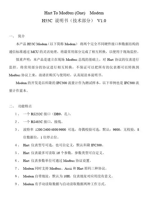
Hart To Modbus (One) ModemH55C 说明书(技术部分)V1.0一、简介本产品H55C Modem(以下简称Modem)将两个完全不同硬件接口和数据结构的通信标准通过MCU的灵活处理,将最常用部分完成了相互转换,以便用于现场监控。
慎重声明:本产品是建立在现场Modbus 总线的基础上,对Hart协议的仪表进行监控。
将常用部分的协议进行相互转换,不保证可以把所有的仪表都可以转换到Modbus协议上来,故请在购买与使用时,认真阅读本说明书。
Modem的开发是以科隆的IFC300流量计作为测试样本,以下举例也是IFC300流量计作蓝本。
二、功能特点1、一个RS232C接口(DB9,孔)。
2、一个RS485C接口,接线。
3、波特率1200/2400/4800/9600可选,奇偶校验可选,默认:9600,无校验,8位数据位,1位停止位。
4、Hart 仪表型号可选,也可自定义,默认科隆IFC300。
5、Hart 仪表最多可读取16个参数,参数类型可自定义。
6、Hart 仪表参数单位可通过Modbus协议设置。
7、Modem同时支持Modbus、Ascii和Hart原码三种协议。
8、Modem自带地址,默认为10H,仪表地址对应用没有意义。
9、Modem有手动读取数据与自动读取数据两种工作方式。
三、技术参数1、供电电压:DC8-35V。
2、供电电流:< 20mA。
3、功耗:< 0.2W。
4、手动读取数据,最快响应1.1秒。
5、自动读取数据,最快响应0.3秒。
四、指示灯说明POWER:电源指示灯,上电即亮。
DATA :通信指示灯,Modem与Hart仪表相互发送数据时,DATA指示灯都会亮,故,Modem向Hart仪表读取数据时,会亮两下,中间间隔为0.2秒。
如果只亮一下,说明Hart仪表没有响应。
STATE :状态指示灯,当Modem接收到Hart仪表数据时会亮,保持10秒。
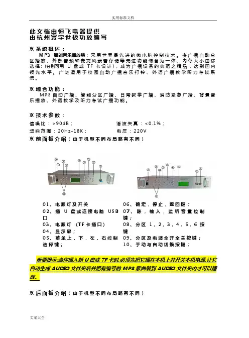
文案大全此文档由恒飞电器提供 由杭州寰宇世极功放编写 ※系统概述: M P 3智能音乐播放器:采用世界最先进的微电脑控制技术。
将广播自动分区播放、外部音频和麦克风录音存储等先进功能综合为一体。
内存大小由你选择: (分别可用U 盘或T F 卡设计),成为广播设备的典范之精品,达到国内领先水平。
广泛适用于校园自动广播音乐打铃、外语广播教学听力考试系统。
※综合功能: M P 3自动广播、智能分区广播、日常教学广播、消防紧急广播、背景音乐播放、外语教学及听力考试广播功能。
※技术参数:信噪比:>90d B ; 谐波失真:<0.1%;频响范围:20H z -18K ; 电压:220V※前面板介绍(由于机型不同布局略有不同)01、电源灯及开关02、插U 盘或连接电脑U S B囗03、电源灯 (T F 卡插囗)04、显示屏;05、菜单上,下,左,右控制选择键;06、确定,停止,返回键; 07、咪,输入,监听音量控制键; 08、分区1,2,3,4,5,6按键 09、分区及电源全开全关按键; 10、手动与自动切换按键; 重要提示:当你插入新U 盘或TF 卡时,必须先把它插在本机上并开关本机电源,让它自动生成AUDIO 文件夹后并把有编号的MP3歌曲装到AUDIO 文件夹内才可以播放。
※后面板介绍(由于机型不同布局略有不同)2注:短路输入端囗: 当这个端囗有短路信号输入时,本机会立刻播放你放在內存里AL A R M 文件夹内的这一首曲目,A L AR M 这文件夹內只能放一首用于紧急报警用的歌曲,其它需要定时播放的歌曲要放在AU DI O 文件夹內,如歌曲的路径放错则定时播放将不执行。
短路输出端囗: 这个端囗与功放电源和分区的动作同步,即当有定时点到时,这端囗即短路,当定时歌曲放完或设定了结束时间到了即断开,这端囗作用是用于控制电源时序器接多台功放之用。
※设备连接图(由于机型不同布局略有不同)01、FM 与遥控天线接囗;03、MIC 输入插孔;05、六个分区输入输出接线座;07、输入电源接线座; 02、音频输入输出插孔; 04、短路输入警报与短路输出控制接口; 06、电源输出接线座;文案大全※音乐播放步骤一:按面板上的” 确定” 键,进入主菜单。
目录1. LCD显示功能概述 (1)2. 按键功能 (2)2.1. 按键功能码速查表 (2)2.2. 按键模式说明 (2)2.3. 数据设置方法 (2)3. 按键操作说明 (3)3.1. 主变量调零(清零)功能 (3)3.2. 组态功能 (3)3.2.1. 功能概述 (3)3.2.2. 设置单位 (4)3.2.3. 设置量程和阻尼 (4)3.3. 组态数据浏览 (4)H3051S / H3051T 按键使用说明书1. LCD 显示功能概述用户可以通过组态软件设置LCD 显示的变量及显示的小数位数。
参见组态软件设置部分的“仪表组态”→“输出特性”。
LCD 支持双变量显示,可以设置的显示变量包括电流、主变量百分比和主变量;每个变量的均可以独立设置显示小数点位置:0、1、2、3、4。
如果两个显示变量相同,则LCD 只显示一种变量;否则,LCD 将以3秒的时间间隔,交替显示所设置的显示变量。
其它显示说明: ¾若在通讯状态,闪烁显示LCD 左上角的。
¾若为开方输出,LCD 显示。
¾若固定输出电流,LCD 显示。
¾若启动写保护,LCD 显示。
¾若启动温度显示,在实时正常显示是,LCD 左下角“88”字符显示温度,温度小于-19℃或大于99℃显示。
2.按键功能通过按键可以调零;零点迁移、量程迁移;设置单位、量程、阻尼。
也可以通过按键查看单位、量程、阻尼等组态数据。
2.1. 按键功能码速查表现场使用按键组态时,LCD左下角“88”字符用于表示当前设置变量类型,也就是当前按键所执行的设置功能。
其对应关系为:左下角“88”字符显示设置变量0或空正常显示1 输入操作码(可以直接输入和下面功能对应的数字,以直接进行相应功能的设置)2 设置单位3 设置量程下限4 设置量程上限5 设置阻尼6 主变量调零7 零点迁移与量程迁移注:通过输入各个功能对应的操作码,可以快速进入对应功能。
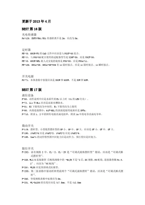
更新于2013年4月BEST第16版光电传感器PA-125,E3F3-R61/R81传感距离不是2m,应改为3m。
定时器PE-40,H3CR-F8的CAD文件中应该是与P2CF-08组合。
PE-44,与P3G-08配合使用的适配器型号是Y29F-30,应是Y92F-30。
PE-48,H3CR-HRL嵌入式安装的底座是P3G-08,应是P3GA-11。
PE-106,H3CA-8H、H3CA-8H-306有1c限时接点,应是1c限时接点、1c瞬时接点。
开关电源PG-71,本体表格中容量应该是300W和600W,不是30W和60W。
BEST第17版液位设备P-58,动作说明中应是水面升到E1以上时(U1的LED灯亮)。
P-72,LL1和BL1应该是高架水槽缺水。
P-81,E2下限用改为中间用,E1下限用改为上限用P-93,内部连接图中:61F-HSL的表面连接用底座应是8PFA。
P-718,附表1、2中的固有电阻改成电阻率,附表1A中的电导改成电导率。
微动开关P-149,摆杆型、小型线型摆杆型的OP小,OP中,OP大,应该是OF小,OF中,OF大。
P-190,1VAP2-6应是1VAP2-2,1VAP2-2应是1VAP2-6。
P-193,XAA-1的动作特性图中回复力应是动作力,预行程应是回复力。
限位开关P-252,命名规格2中,CL-2、CL-2N是“可调式滚珠摆杆型”错误,应该是“可调式棒式摆杆型”。
P-253,WLI/O连接器型⑤配线规格中的 -M1JB不是“2芯,DC规格、NO配线、连接器查缴No.3、2”,应改为“NC配线”。
P-254,WLD3应是顶部球式柱塞型。
P-255,第二张表格中驱动杆种类前两个“可调式滚珠摆杆”错误,应该是“可调式棒式摆杆”。
P-268,导线规格表格中标准应为5m。
P-281, WL-3A200的长度应该是417.5mm,不是412.5mmP-295,D4A-D00对应的驱动杆的种类不是“可调式滚珠·摆杆型”,应该改成“可调式棒式·摆杆型”。
常新电子编程定时器CX-T02 定时开关定时插座使用指南【产品操作说明】★系统功能模式介绍:本机在时钟状态下,按“模式”键可将工作状态设定为如下5种模式:关→自动→开→循环→ZZ(倒计时)关 ---电源输出处于常关状。
自动---电源输出处于执行编写的定时开/关程序状态。
开 ---电源输出处于常开状。
循环---电源输出按照你设定的开启时间长度和间隔时间长度(关闭时长)来循环工作。
ZZ ---电源输出处于倒计时(延时关机)状态,最长时间为23小时59分,最短为1分钟。
C ---按此键后系统将清除所有储存的数据,系统恢复到初始状态。
★操作方法(一)、校正星期和时间:按“模式”键将定时器工作状态设定为“关”,在此状态下左手按住“时钟”键不放,右手按“日期”键,将星期调整为当前日期,调整好日期(星期)后再按“时”和“分”键将时钟调整为当前的标准时间。
(二)、设定倒计时(延时关机)时间:按“模式”键将工作状态切换至ZZ状态,电源输出即处于开启状态(初始默认时间为11小时59分),在此状态下,按“时”和“分”键修改您所需要本机开启通电的时间,最大设定时间为23小时59分,设定完成后按“时钟”键,系统即进行倒计时,待时钟退至0:00后,电源即自动关闭,15秒后自动恢复到时钟状态。
(三)、12/24小时转换制:在关/开的工作状态下,按住“时钟”键不放,再按S/A键,时钟即显示为12小时制,此时屏幕左边显示A或P,A上午,P下午。
(四)、键盘锁定功能:在任意状态下,先按住“时钟”键不放,再按住“模式”键3秒。
键盘即被锁定,锁定后屏幕右上角出现钥匙标志。
如需进行其它操作,必须仍按上述方法解锁后才能进行操作。
(五)、设定循环定时:按“模式”键将工作方式转换成“循环”,此时按“设定”,屏幕出现小灯炮标志,此时按时、分键,设定您需要的开启时间长度,再按设定键,出现一个打叉的小灯泡标志,同上设定关闭的时长。
最大设定时间长度为23小时59分,最短为1分钟。
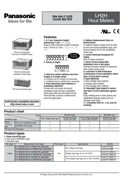
Product types1. Panel mounting type1) One-touch installation typePanel mounting type One-touch installation typePanel mounting type Installation frame typePC board mounting typeFeatures1. 8.7 mm Character Height (previously 7 mm .343 inch )Easy-to-read character height increased from 7 mm to 8.7 mm .276 inch to .343 inch .2. Plenty of Digits3. Select by switch between two time ranges in a single meter.0 to 999999.9h/0 to 3999d23.9h switchable 0 to 999h59m59s/0 to 9999h59.9m switchable4. Panel Mounting Type Features 2 Installation MethodsComes with very easy one-touch installation type and also installation frame type that uses the frame on the timer/counter. Choose a method that suits the application.5. Battery Replacement Easy on EnvironmentT o replace battery simply remove body for the one-touch installation type, and remove battery lid for the installation frame type.6. Screw Terminals Designed for SafetyBuilt in finger protection.7. Panel Covers Replacable (Standard color is ash gray.)Change the panel design by replacingwith a black panel cover.8. Conforms to IP66 ProtectiveConstruction (Only installation frame type.) (Front panel surface)9. Input Methods1) Non-voltage input method 2) Voltage input method3) Free voltage input method10. Backlight Type Added to Series and Now 2-color Switchable (green/red)Easy viewing even in dark places and switchable between green and red (Voltage input type).11. Compliant with UL, c-UL and CE marking.RoHS Directive compatibility information/Product chart2 Backlight typeSpecificationsNote) Only for installation frame type.Applicable standardPart names1. Front reset buttonReset the elapsed time. It does not work when the lock switch is ON. Be aware that battery life will decrease if this switch is used frequently.2. Lock switch (Refer to chart on right.)Disable the front reset button.Note)T urn ON at the LCD side (reset disabled) andOFF at the terminal block side (reset enabled).3. Time range switch (See chart on right).Switch the time range.Note)Always press the front reset button whenoperating the time range switch.4. Time unit stickerUnit seals are included in the package. Affix them in accordance with the time range.Notes)1.❇Default setting when shipped.2.Make the switch setting before installing to panel.Dimensions1. Panel mounting type • External dimensions1) One-touch installation typemm inchGeneral tolerance: ±1.0 ±.039• Panel installation diagramNote)When installing to a 4.5 mm .177 inch thick panel, remove the rubber spacerfirst.When installing the one-touch installation type model, make sure that the installation spring does not pinch the rubber gasket.T o prevent the installation spring from pinching the rubber gasket:1. Set the rubber gasket on both ends of the installation spring (left and right).2. Confirm that the installation spring is not pinching the rubber gasket, and then insert and fix the installation spring in place from the rear of the timer unit.• Terminal layout and wiring diagrams2) Installation frame type• Panel mounting diagramMounting screwsMounting frame • Panel cut-out dimensionsThe standard panel cut-out is shown below.Use the mounting frame (ATH3803) and the rubber packing (ATH3804).(Only installation frame type.)• For connected installation (sealed installation) (Only installation frame type.)Notes)1. Suitable installation panel thickness is 1 to 4.5 mm .039 to .177 inch .2. Waterproofing will be lost when installing repeatedly (sealed installation).A=(1.890×n-.098)0+.0390Input methodNotes)1.2 and 4. (The input and reset circuits are functionally insulated.)2.When using transistor (T r) input, use the right as a guide. (Collector withstand voltage Q 50 V , leakage current < 1 µA)3.Be aware that the application of voltage that exceeds the voltage range of the H level to the count input terminal, and the application of voltage to the reset input terminal, can cause damage to the internal elements.2. PC board mounting type • External dimensions• Terminal layout and wiring diagramsGeneral tolerance: ±1.0 ±.039 mm inchPC board pattern (BOTTOM VIEW)General tolerance: ±0.1 ±.004Note: The AXS212811K is recommended as a compatible connection socket.Q -E , }-w , e -t and S -F are connected internally.An external power supply is required.Connection sockets 28 pin DIP terminalNotes)1.Do not reverse the polarities when connecting the DC voltage for the backlight.2.2 and 4. (The input and reset circuits are functionally insulated.)3.When using transistor (T r) input, use the right as a guide. (Collector withstand voltage Q 50 V , leakage current < 1 µA)4.Be aware that the application of voltage that exceeds the voltage range of the H level to the count input terminal, and the application of voltage to the reset input terminal, can cause damage to the internal elements.Explanation of operation1. Time measuring takes place when the start input is ON.2. When the elapsed (measured) time reaches full scale it returns to “0”, and then measuring starts again from “0”.3. When reset input is ON, the display becomes “0”. Y ou cannot measure during reset input.For PC board mounting type the display disappears while the reset input is ON; however, the display reads “0” when the reset input turns OFF .4. Press the front reset button if you want to perform a manual reset (for panel installation type)Cautions for use1. Non-voltage input typeFor both panel mounting and PC board mounting types1) Never apply voltage to the non-voltage input type. This will damage the internal elements.2) Since the current flow is very small from the start input and reset input terminals (1 and 3 on the panel mounting type and terminals e to t and S to F on the PC board mounting type) please use relays and switches with high contact reliability. When inputting with an open collector of a transistor, use a transistor for small signals in which ICBO is 1 µA or less and always input with no voltage.3) When wiring, try to keep all the input lines to the start and reset inputs as short as possible and avoid running them together with high voltage and power transmission lines or in a power conduit. Also, malfunctions might occur if thefloating capacitance of these wires exceeds 500 pF (10 m 32.808 ft. for parallel wires of 2 mm2). In particular, when using shielded wiring, be careful of the capacitance between wires.PC board mounting type1) For external power supply use manganese dioxide or lithium batteries (CR type: 3V).2) Always reset after external power is applied and confirm that the display reads “0”.3) Make the wiring from the battery to the hour meter unit as short as absolutely possible. Also, be careful of polarity.4) Calculate battery life with the following formula.t = A/It: battery life [h]I: LH2H current consumption [mA]A: battery capacity until minimumoperation voltage is reached [mAh] 5) Hand solder to the lead terminal. Do not dip solder. With the tip of the soldering iron at 300°C 572°F perform soldering within 3 seconds (for 30 to 60 W soldering iron).2. Voltage input type1) Be aware that applying more than 30 V DC to start input terminals 1 and 2, and reset input terminals 3 and 4 will cause damage to the internal elements.2) For external resetting use H level (application of 4.5 to 30 V DC) between reset terminals 3 and 4 of the rear terminals. In this case, connect + to terminal 3 and – to terminal 4. This is the valid polarity; therefore, the hour meter will not work if reversed.3) When wiring, try to keep all the inputlines to the start and reset inputs as shortas possible and avoid running themtogether with high voltage and powertransmission lines or in a power conduit.Also, malfunctions might occur if thefloating capacitance of these wiresexceeds 500 pF (10 m 32.808 ft. forparallel wires of 2 mm2).3. Free voltage input type1) Use start input terminals 1 and 2 forfree voltage input and reset terminals 3and 4 for non-voltage input.2) Be aware that the application ofvoltage that exceeds the voltage range ofthe H level to the start input terminal, andthe application of voltage to the resetinput terminal, can cause damage to theinternal elements.3) Since the current flow is very smallfrom reset input terminal 3, please userelays and switches with high contactreliability.4) When inputting a reset with an opencollector of a transistor, use a transistorfor small signals in which ICBO is 1 µA orless and always input with no voltage.5) T o reset externally, short reset inputterminals 3 and 4 on the rear.6) Input uses a high impedance circuit;therefore, erroneous operation may occurif the influence of induction voltage ispresent. If you plan to use wiring for theinput signal that is 10 m or longer (wirecapacitance 120 pF/m at normaltemperature), we recommend the use ofa CR filter or the connection of a bleederresistor.4. How to reset multiple panelmounting type counters all at once(input is the same for count)Non-voltage input typeNotes)e the following as a guide for choosingtransistors used for input (Tr).Leakage current < 1 µAe as small a diode (D) as possible in theforward voltage so that the voltage betweenterminals 3 and 4 during reset input meetsthe standard value (0.5 V).( At IF = 20 µA, forward voltage 0.1 andhigher.)Voltage input typeNote)Make sure that H (reset ON) level is at least 4.5V.5. Backlight luminanceT o prevent varying luminance amongbacklights when using multiple Backlighttypes, please use the same backlightpower supply.6. Acquisition of CE markingPlease abide by the conditions belowwhen using in applications that complywith EN 61010-1/IEC 61010-11) Ambient conditions• Overvoltage category II, pollution level 2• Indoor use• Acceptable temperature and humidityrange: –10 to +55°C, 35 to 85%RH (withno condensation at 20°C)• Under 2000 m elevation2) Use the main unit in a location thatmatches the following conditions.• There is minimal dust and no corrosivegas.• There is no combustible or explosivegas.• There is no mechanical vibration orimpacts.• There is no exposure to direct sunlight.• Located away from large-volumeelectromagnetic switches and powerlines with large electrical currents.3) Connect a breaker that conforms toEN60947-1 or EN60947-3 to the voltageinput section.4) Applied voltage should be protectedwith an overcurrent protection device(example: T 1A, 250 V AC time lag fuse)that conforms to the EN/IEC standards.(Free voltage input type)7. Terminal connectionTighten the terminal screws with a torqueof 0.8 N·cm or less.。
CX-T02(W)型、CX-T03型可编程多功能电子定时器使用说明书一、产品简介:CX-T02(W)型、CX-T03型可编程多功能电子定时器,是以微电脑处理器为核心配合电子电路等组成的电源开关控制装置。
它可预设定每天或一周内20次不同时间的开/关控制,还具有倒计时、任意循环定时、键盘锁定功能和12/24小时制转换功能。
本机内置一枚可充电镍氢电池作为备用电源,在脱离市电电源的情况下,仍可保持计时显示和储存的各项数据达9个月以上。
它采用便携式移动插头形式和微功耗待机电路,可以控制电热水器、电饭煲、饮水机、电动自行车限时充电控制、灯具等各种电器。
您使用本产品后,各种电器将根据您的要求实现自动开启和关闭,既省电又方便,是真正的节电产品。
二、技术参数:执行标准:GB/T14536.1-2008 GB/T14536.8-2010额定电压:220V ~50Hz额定电流:CX-T02(W)型10A(阻性)CX-T03型16A(阻性)工作温度:-20~70℃计时误差:≤±1秒/天三、系统功能介绍:1.液晶全屏字符,如右图所示:2. 本机在时钟状态下,按“模式”键可将工作状态设定为所需的方式。
设定顺序为:关自动开循环 Z Z(倒计时)关电源输出处于经常关闭状态。
自动电源输出处于执行编写的定时开/关程序状态。
开电源输出处于经常开启状态。
循环电源输出按照您设定的开启时间长度和间隔时间长度(关闭时长)来循环工作。
Z Z电源输出处于倒计时(延时关机)状态,最长时间为 23小时59分,最短为1分钟。
C 按此键后系统将清除所有储存的数据,系统恢复到初始状态。
S/A 时钟状态时夏时制转换、12/24小时制转换的按键,在设定自动程序时是清除数据的按键。
模式工作状态功能转换的按键。
四、操作方法在本机进入时钟状态后,可按以下方法进行操作:(一)、校正星期和时间:按“模式”键将定时器工作状态设定为“关”,在此状态下左手按住“时钟”键不放,右手按“星期”键,将星期调整为当前日期,调整好日期(星期)后再按“时”和“分”键将时钟调整为当前的标准时间。
神盾H5产品使用说明书神盾H-5产品运用说明书目录一、系统组成二、产品功用及技术参数三、设备装置四、软件运用及说明五、罕见缺点处置六、客户效劳及技术效劳承诺一、系统组成神盾H-5系统由以下几局部组成1、管理电脑2、巡更机〔神盾H-5〕3、巡更点4、人员卡〔可选〕5、智能巡检管理软件6、充电器7、锂电池8、皮套2、巡更点集成电路芯片密封在外壳内,防水防腐蚀,稳固耐用,可在各种恶劣环境中运用。
每个感应器编号不重码,无需供电。
识读卡次数:〉35万次寿命:一体式〉20年;卡片式〉10年环境温度:-40℃∽+85℃尺寸:直径8.5CM,,厚度:1CM重量:50g3、电脑通讯电缆采用USB数据通讯线,运用复杂方便,下载数据速度快4、电池及充电器锂电池购置产品时所带的电池为不饱和形状,因此需求充溢后再运用。
假设电池电压不够时,上电后液晶显示屏发现〝请充电〞指示,这时需求对电池停止充电,否那么形成电池过量放电招致电池损坏。
充电器运用方法1)将待充电电池按正确方法放入充电器上2)充电时充电器指示灯为白色表示下在充电中,当充电器指示灯变为绿色时,表示电池已充电完成本卷须知1)勿将充电器置于湿润和高温环境下2)在运用进程中会有一定发热,在正常室温时,发热不超越60°C属于正常状况,是不会损坏锂电池3)新电池要充放三次才干到达最正确效果4)电池运用保证期为六个月5)电池抗抗震才干弱,请防止巡检器的剧烈冲击6)风险场所请勿装配电池,严禁通讯,严禁充电5、产品运用功用说明USB接口指示灯开机键«开机功用键»功用说明:1〕开机键:当按下此键时,巡更机自动开启,进入读卡形状«指示灯»功用说明:1〕开机指示灯为白色,读卡成功后显示为绿色,读卡成功后并有振动提示«USB接口»功用说明:1〕USB与电脑通读接口二、设备装置1、巡更点装置1)首先确定巡更点装置位置,再拿冲击钻对准装置点冲〔三个孔〕嵌入胶塞。
文案大全此文档由恒飞电器提供 由杭州寰宇世极功放编写※系统概述:M P 3智能音乐播放器:采用世界最先进的微电脑控制技术。
将广播自动分区播放、外部音频和麦克风录音存储等先进功能综合为一体。
内存大小由你选择: (分别可用U 盘或T F 卡设计),成为广播设备的典范之精品,达到国内领先水平。
广泛适用于校园自动广播音乐打铃、外语广播教学听力考试系统。
※综合功能:M P 3自动广播、智能分区广播、日常教学广播、消防紧急广播、背景音乐播放、外语教学及听力考试广播功能。
※技术参数:信噪比:>90d B ; 谐波失真:<0.1%;频响范围:20H z -18K ; 电压:220V※前面板介绍(由于机型不同布局略有不同)01、电源灯及开关02、插U 盘或连接电脑U S B 囗03、电源灯 (T F 卡插囗)04、显示屏;05、菜单上,下,左,右控制选择键; 06、确定,停止,返回键; 07、咪,输入,监听音量控制键; 08、分区1,2,3,4,5,6按键 09、分区及电源全开全关按键; 10、手动与自动切换按键;重要提示:当你插入新U 盘或TF 卡时,必须先把它插在本机上并开关本机电源,让它自动生成AUDIO 文件夹后并把有编号的MP3歌曲装到AUDIO 文件夹内才可以播放。
※后面板介绍(由于机型不同布局略有不同)2注:短路输入端囗: 当这个端囗有短路信号输入时,本机会立刻播放你放在內存里AL A RM 文件夹内的这一首曲目,AL A RM 这文件夹內只能放一首用于紧急报警用的歌曲,其它需要定时播放的歌曲要放在A U DI O 文件夹內,如歌曲的路径放错则定时播放将不执行。
短路输出端囗: 这个端囗与功放电源和分区的动作同步,即当有定时点到时,这端囗即短路,当定时歌曲放完或设定了结束时间到了即断开,这端囗作用是用于控制电源时序器接多台功放之用。
※设备连接图(由于机型不同布局略有不同)※音乐播放步骤一:按面板上的” 确定” 键,进入主菜单。
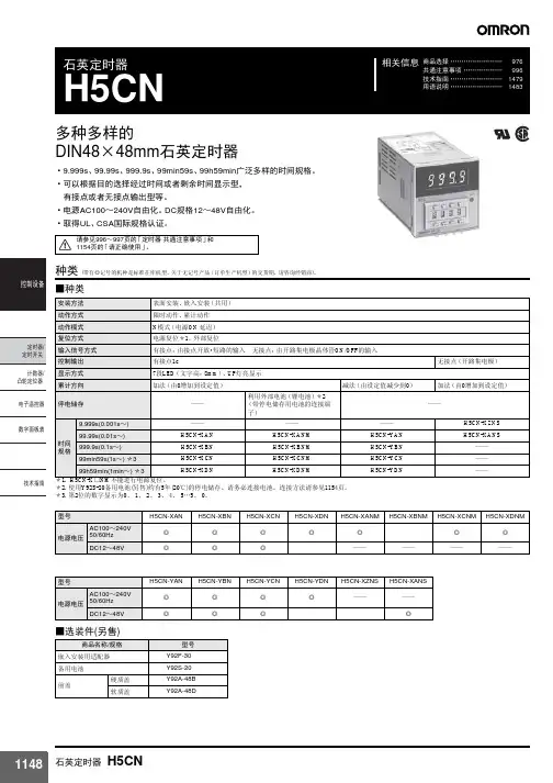
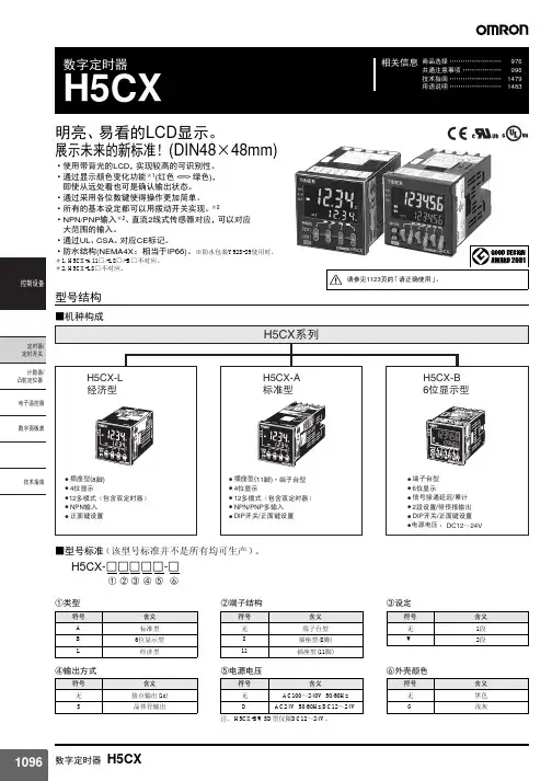
商品选择 ........................978共通注意事项 ..................996技术指南 ........................1479用语说明 (1483)相关信息数字全天式时间开关H5F1天的时刻控制可以简单操作(可以选择动作日)•ON/OFF 时刻设定有24步。
•对应CE 标记。
通过UL 、CSA 标准认证。
•采用假日功能,轻松应对国定假日等突发性假日。
•利用测试模式功能,简单确认程序。
•采用半自动动作,可应对突然的日程更改•可以实现脉冲动作,应对夏令时。
•所有机种具有防指触保护。
•具有嵌入式安装、表面安装、协约尺寸型等各种类型。
•跨日动作同全天动作设置一样。
请参见996~997页的「定时器 共通注意事项」以及1195页的「请正确使用」。
P SEH5F-AH5F-FA H5F-KAH5F-KAL型号结构■型号标准(该型号标准中,有些不能制作)H5F-□□□① ② ③种类■机种结构*关于H5F-KAL 的英文表示式样详情请另行垂询。
■选配件(另售)安装方法嵌入式安装表面安装表面/DIN 导轨安装(协约型)项目纵向横向日文规格型号H5F-A H5F-FA H5F-KA H5F-KAL英文规格型号H5F-BH5F-FBH5F-KB*商品名称/规格型号备注软质盖Y92A-48F1防尘盖H5F-A/-B 用Y92A-48H5F-FA/-FB/-KA/-KB/-KAL 用Y92A-48E 协约尺寸型(H5F-K □)附属在本体中。
嵌入式安装用适配器Y92F-30嵌入式安装型(H5F-A/-B )附属在本体中。
①安装方式符号含义无嵌入式安装F 表面安装K表面/DIN 导轨安装(协约型)②表示符号含义A 日文表示B英文表示③安装方向符号含义无纵向L横向额定值/性能■额定值■性能*1.包括动作时间重复精度、设定误差、电压的影响、温度的影响在内的综合误差在(±0.01%±0.05秒)以内。