rgh22系列读数头安装手册
- 格式:pdf
- 大小:1.10 MB
- 文档页数:9


重要提示鉴于这些测量仪器为精密仪器,为了确保操作是在设备铭牌所示范围内,因此当你在安装、使用及维护时,必须遵守丹尼尔指南进行。
当在进行安装、使用及维护丹尼尔产品时,应遵守下列提示并将其纳入你的安全工作计划中。
●在进行安装、操作及维修该产品前,应阅读所有说明。
如该手册并非是正确的,请拨打1-713-467-6000(24小时全天侯销售及维修服务支持),尔后将为您提供所需要的手册。
您可保存该手册以供将来参考之需。
●如您对本手册有任何问题不清楚,请联系你的丹尼尔销售代表获得解释。
●请遵照产品所标示及所附的警告、注意事项及说明。
●应教导你的人员进行正确的安装、操作及维护该产品。
●进行安装设备时应按照正确的说明书所指示的要求及当地规范和国家规范。
将所有产品连通适当电源及施加正确的压力。
●为了确保产品的良好性能,应雇用专业的人员进行安装、操作、更新、编排及维护该产品。
●当某部件需要更换时,应确保进行更换工作的专业人员是使用生产商指定的部件。
未经授权的部件及操作流程会对产品的性能产生影响,并会引发操作中的事故隐患。
看起来很相似的替换部件可能会导致火灾、电路短路或不正常的操作。
●为了预防人员受伤,应确保所有设备的门已关闭、保护性的盖子已归位,除非专业人员正在对其进行维修。
●必须始终阅读及遵守《丹尼尔高级超声波气体流量计安装、维修及诊断说明书》和所有产品警告及说明书●如该产品使用于其它非指定用途,可能会导致财产损坏和/或严重人员伤亡。
●在易燃情况下打开产品防火外壳时,必须切断供电。
操作步骤:1. 应先断电。
丹尼尔测量与控制有限公司丹尼尔高级超声波气体流量计安装、维修及诊断说明书注意丹尼尔测量与控制公司(简称丹尼尔公司)不对本说明书的技术或编辑错误及遗漏所负责。
就本说明书而言,丹尼尔公司不作出无论明示或暗示,包含暗示的可为商品性及其适用的目的之保证;并且在任何情况下,丹尼尔公司不对任何特殊及间接损害,包括但不仅限于产品损失及得益损失等等负责。

Knowledge BaseArticle Type: InstructionsCylinder Installation –Compression/Stripper, for Models,22HF, 16HF, 1600 machinesDescription:Instructions on “How to” properly install stripper beam and compression head cylinders. Included is information on the Safety Beam Stops kit.WARNINGNever work on, clean or service this unit, control panel or any machine or open or remove any protective cover, guard, grate, door, or maintenance panel until the power or energy sources has been turned off, locked out / tagged out, and all moving parts have come to a complete stop and or blocked to prevent movement. Machinery is dangerous –avoid personal injury and or death by following manufacture, Local, and OHSA safety procedures. Contact Columbia Machine for safety decals, guards, horns and beacons.INSTALLATION PROCEDURES FOR STRIPPER AND COMPRESSION CYLINDERS FOR FLOOR LEVEL MACHINES MODEL 22, 16 AND 1600Safety First: Always follow your safety guidelines for system lockout/tagout of electrical panels and the hydraulic system.The proper installation for stripper and compression cylinders is very important to ensure good life of the cylinders and their components. It is also important to check the front end of your machine for front-to-back play and side-to-side play as this can lead to shorter life of your cylinders.Upon receiving your compression cylinders or stripper cylinders they should be checked for any damages that may have occurred during shipping. Check the bottoms of the stripper cylinders for nicks or scratches. If noticed, use a flat file single cut fine to remove nicks or scratches. Only remove raised area. Also check for rust at the bottom of the stripper cylinders or any additional rust on the rod ends of the stripper or compression cylinders due to water damages. If light rust is noticed on the bottom of the stripper cylinders, you should use either of the following two hand pads listed below: Hand pad made by 3M Scotch-Brite general purpose color (Maroon) or Bear-Tex made of non-woven nylon web perfect for hand cleaning general all purpose color (Gray)These pads will remove rust and oxidation, and will clean & polish with gentle action and no effect on dimensions. Once cleaned, if you’re not installing them on the machine at this time and will be placing them in the store room, make sure that you coat the base and cylinder rods with a light coat of grease to protect the bare surfaces. Also make sure that either plastic plugs or O-ring plugs are installed in all ports.Please see pictures below for referencing:Clean stripper cylinder base with Scotch-Brite or Bear-Tex hand pads. Using a flat fine tooth file remove any scratches or nicks raised areas only.Using a straight edge check cylinder base for flatness across in three areas: up, down, and diagonally. Check the base foot area of the machine box where the stripper cylinder will mount. Ensure that there are no scratches or nicks and that the surfaces are flat for mounting the cylinders. Make sure to clean all threaded holes thoroughly. Apply a small amount of anti-seize lubricant to the bolts or threaded holes.be made or cylinder damages will occur.You can also verify dimensions by using a straight edge on the top machined surface of the main box and measuring down to the top of the stripper beam. Again these dimensions should be within 1/16 inch from side-to-side. Front end alignment problems could be caused by worn main shafts, bushings, guide tubes, column brackets or stripper beam worn due to guide tube clamp rings not holding guide tubes tight in beam. Lower height stops set incorrectly causing beam to rack or possibly area were stops contact lower stripper beam. For information on adjustment, front end alignment and stripper beam repairs, contact Columbia Machine service department at 1-800-628-4065 for assistance.Stripper cylinder installation:Once you have confirmed the beam is level with the main machine box and the cylinder base and machine foot area is ok cleaned free of scratches or nicks threaded holes cleaned, you are ready to install your stripper cylinders. Make sure you have installed the hydraulic fittings in both the base and rod cap and install the hardened washer on the rod.With stripper beam resting on lower beam stops install the cylinder on machine foot rest area and using anti-seize apply a small amount to either the “new grade 8 bolts orthreaded holes”. Always use new bolts and lock washers when changing out cylinders.Make sure the hardened washer has been installed on the rod assembly. Install the bolts by hand, threading them down as far as possible. Using either a box end wrench orratchet wrench, snug the bolts down in a cross hatch pattern watching the alignment of the rod to the stripper beam where the rod will pass through the beam. Using a torque wrench, tighten the bolts up to torque in three equal settings using a crosshatch pattern.For floor level machines model 22, 16 & 1600, the bolts are a 5/8-18 NF Grade 8 bolts.Full torque is 187 foot pounds lubed. With all bolts torqued to specs, the cylinder rod should pass through the beam without touching the sides of the beam. With thehydraulic hoses attached and the machine slow valve closed for slow operation, begin to raise the rod through the stripper beam making sure the rod does not touch the side of the beam as this can damage the rod seal or cause misalignment with the cylinder causing failure. If the rods move up through the beam without touching, continue to raise the cylinder until the beam is raised to full stroke. Place enough beam stops on the lower height stops and begin to lower the cylinder allowing the rod to disengage from the beam.Make sure the rod, again, is not touching the sides of the beam as it leaves the beam. In the event that the rod is being forced over either when it leaves the beam or will not enter the beam without forcing, back the bolts off at the base and try to move the cylinder over slightly taking up any gap between the holes in the base of the cylinder. Again using a crosshatch pattern begin torquing the bolts down in three equal settings. Once thecylinder has been aligned and the rod can pass through the beam in either the full upposition or down position, you are ready to install the locknut on the rod. Torque the rod locknut to 600 foot pounds on a model 22, 16 or 1600. Columbia Parts has a newlocknut that has more surface area locking against the main beam. The locknut partnumber is 100155.16.Hardened washer.New locknut.With cylinder installed and air evacuated from the cylinder, raisebeam up and down several times, watching both cylinders andbeam for any binding or racking. If all works fine open, slow valveup and back cushions out 1 ½ turns. This is the initial setting.Again raise and lower the beam several times, watching for bindingor racking and to make sure you have a good cushion at the end ofstroke. Once testing has been completed, shut the system down,lock the pump out and apply a small bead of silicone around thebase of the cylinder to the base of the machine foot.Once oil has reached operating temperature, you may need to adjust cushions for smooth cushioning at end of stroke or racking of the beam.Compression cylinder installation:When changing out a compression cylinder or stripper cylinder you should always try tofigure out what may have caused the failure. Contamination to the hydraulic system dueto parts failure or binding of the compression beam or stripper beam, worn or loose frontend allowing the beams to move too much, breaking the rod assembly or damaging therod seal or piston seals. What about the air stroke assembly? Does the air strokeassembly move freely? What’s the condition of the guide rods, bottom support bar,bumper rubber, bushings air bags? Due to the costs of these parts and the lost productiondown time repairs, these questions should be answered as you could possibly lose anothercylinder in a very short time.Locknuts are Columbiamanufactured as the threadsmust be true to the nut facing. The compression cylinder rod is attached to the compression beam through the air stroke assembly. These components must be in good condition and move freely. If binding occurs in the air stroke assembly, this could cause racking of the compression beam which could break the rod assembly or damage the cylinder seals along with other damages that may occur. Inspect these parts and replacement of worn or damage items should be done when replacing a compression cylinder.Prior to installing the cylinder into the stripper beam, install the hydraulic fittings and position them in the right orientation at the base of the cylinder. Clean the threaded holes out in the stripper beam and apply a small amount of anti-seize to the threads or on the bolt threads. Remove the shipping bolt and nut holding the rod cap and bottom plate together. Once removed, be careful not to allow the cylinder tube and cap to separate and slide the compression cylinder down into the stripper beam. Make sure that you position the cylinder so the rod cap porting is facing in the correct orientation to hook up the hoses. Install the (4) socket head bolts threading them into the stripper beam. Using a crosshatch pattern snug the bolts down, but do not torque at this time. Hook up the tube assembly at the base of the cylinder and hose at the rod cap.In the picture above you will notice that the compression rod has a nipple at the threaded end of the rod. When threading the rod into the air stroke assembly bottom support bar, it must be bottom out in the support bar. This ensures that the mating threads of the rod and support bar are seated. Never adjust the cylinder rod out to correct any racking of the beam. The rod must be bottomed out in the support bar. Always use Columbia Machine special jam nuts as they are manufactured with the threads true to the facing. Standard jam nuts are not true 90 degrees to the face. Cylinder rod breakage can occur if not using the Columbia manufactured jam nuts.With bolts installed and hydraulic hoses and tubes hooked up, you are ready to align the rod to the air stroke assembly. As we discussed for stripper cylinder installation, please follow the same procedures for checking beam alignment. Once you have confirmed that the stripper beam is level, true to the block machine main box and you have checked from the top of the stripper beam to the bottom machined surface of the compression beam and both sides are within 1/16 from side-to-side, you can begin to torque the bolts using a crosshatch pattern. Torque the cylinder down to the stripper beam using three equal torque settings. For model 22 socket head cap screw ½ -13 UNC torque to 70 to 80 foot pounds max. Model 16 and 1600 floor level machine 5/8 – 11 UNC torque to 90 to 100 foot pounds max.Columbia manufactured jam nut & compression cylinder rod end.As you are torquing the bolts, watch the rod move around at the top. When you get to your final torque setting, the rod should be aligned with the bottom retainer bar threaded hole. With the jam nuts installed on the rod, run them down to the bottom of the threads and lock them together. Apply anti-seize to the threads. Check to make sure the hydraulic connections are tight. Remove your locks from the pump and main panel making sure the machine slow valve is set for slow operation.Turn the pump on and raise the cylinders just enough so that the nipple of the rod enters the bottom retainer bar. Turn the pump off and lock out the system. Turn the air off the head air bags. With the air off, the air stroke assembly should drop down slightly when the air is evacuated from the air bags. This will allow you to start threading the rod into the bottom retainer bar by hand or with the use of an open end wrench. You should not have to force the rod in or push the rod from side-to-side to start threading the rod in. If you have aligned the rod correctly when you were torquing the cylinder bolts down to the stripper beam you should be able to thread the rod into the bottom retainer bar. Once the rod is bottomed out give a couple hard jerks with the wrench to set the rod tight into the retainer bar. Break the jam nuts loose and tighten each one against the retainer bar and jam nut.On some compression cylinders, rather then a built in cushion on the rod end cap, we have adjustable cushions installed. For initial settings screw the adjusting screw in clockwise until it bottoms out and back out 1 ½ turns. During setup you may need to adjust one side more then the other to eliminate beam racking from side-to-side. Once the oil has warmed to operating temperature you may need to adjust the cushions a little more. Screwing the cushion in clockwise increases cushion out and counter clockwise decreases cushion. Adjust cushions so that the beam does not bang hard at the end of stroke when going up and eliminate side racking of the beam.Cushion adjustment.With the cylinder or cylinders installed you, are ready to make your final settings. Remove locks from system and start pump. Again keeping the slow valve in position for slow operation raise and lower compression beam several times watching for any leaks. Turn head air back on. Place the slow valve in fast operation and run the compression beam up and down. Make sure the stripper beam is in the up position so that full stroke of the cylinder is made. Check for side to side racking of the beam and make adjustments to the cushions. Also adjust cushions just enough so that you have a good cushion at end of stroke going up without the beam banging at end of stroke. Check the down stroke for racking as well. If the beam lags behind on the right side as you begin to start down, back out the cushion slightly. Run the beam up and down several more times. Once the beam can travel to its full up position and down position without racking or banging, you have completed the adjustments. Remember, once the oil warms up to operating temperature, it may be necessary to make adjustments to the cushions again.With both compression and stripper beams in the down position, turn the power off and lock out the system. As an added protection to keep contamination from getting into the threads where the cylinders have been bolted down, it is suggested to apply a small amount of silicone around the base of the cylinders and lock washers. This will aid in keeping the bolts and threads clean from contamination.This completes the stripper and compression cylinder installation. For additional information or service help, please call Columbia Machine Inc. at 1-800-628-4065. Please review information below for Safety Beam Stops application for compression beam and stripper beam for added safety during mold changes, adjustments and repairs.SAFETY BEAM STOPS COMPRESSION BEAM STOPS FOR FLOOR LEVEL MACHINES MODEL 22,16 AND 1600Safety first: Always follow your safety guidelines for system lockout/tagout of electrical panels and the hydraulic system.The installation and use of the new compression beam stops is to maintain compression beam up during mold change, feed drawer strike off plate adjustment or additional repairs or adjustments that require plant personnel to be working in and around the machine with the beam in the up position. The hydraulic circuit for the compression beam on some machines has a P.O. check valve and on others you have a P.O. counterbalance valve. Both these style check valves hold pressure on the base end of the compression cylinder until the valve is energized down which uses pilot pressure to open the check valve or counterbalance valve. In the event that one or both compression cylinders are allowing hydraulic oil to bypass the piston seals the beam will drift down slowly or fast depending on the condition of the seals. Other hydraulic failures can cause the beam to not stay up which could include failure to the P.O. Check valve or P.O. counterbalance valve.The beam stops are a positive stop between the compression beam and stripper beam which in the event that either loss of hydraulics, failure to the compression cylinder or P.O. check valve, P.O. counterbalance valve the beam stops will maintain beam in up position.The following pictures below show the installation of these new positive beam stops:(more pictures next page)LOWER STRIPPER BEAM STOPS FOR FLOOR LEVEL MACHINES MODEL22, 16 AND 1600In addition for mold installation, adjustments or repairs use your lower stripper beam stops to aid in holding the stripper beam in the up position install additional stops as required. The stripper hydraulic circuit also has either a P.O. check Valve or P.O.counterbalance valve that maintains hydraulic oil to the base of the cylinders. The same failures can occur on the stripper circuit as with the compression beam. The mechanical stops are an added safety for maintaining the beam in the up position during moldchanges, cylinder replacements, vibrator & shaker shaft repairs or replacement where you will be required to have your hands in and under the beams.Please see pictured below stripper beam stops:For more information or to order a set of beam stops please contact Columbia Machine, Inc. parts department 1-800-628-4065.Use additional stops as required during mold changes, adjustments or。


取样探头222.15/17/20/21/31/35安装及使用说明书BC460017, 07/2017 Art. Nr. 90 31 059Bühler Technologies GmbH, Harkortstr. 29, D-40880 RatingenTel. +49 (0) 21 02 / 49 89-0, Fax. +49 (0) 21 02 / 49 89-20AP000005请在安装和使用前仔细阅读此手册。
敬请特别注意所有安全守则,以避免不必要的意外伤害事故。
Bühler Technologies GmbH /德国比勒科技有限责任公司对由不当操作以及在未授权情况下擅自改动机器设备所引起的后果不承担任何责任。
目录页1概述 (4)2重要注意事项 (4)2.1安全注意事项概述 (5)3铭片说明 (6)4产品说明 (6)4.1概述 (6)4.2发货内容 (6)5运输及存储要求 (7)6安装及线路连接 (7)6.1安装 (7)6.2探管的连接 (8)6.2.1样气管的连接 (9)6.2.2校正气体管的连接(可选) (9)6.3反吹和反吹气罐的连接(适用于 GAS 222.21, 31 和 35) (9)6.4电子线路连接 (10)6.4.1型号 GAS 222.15 / GAS 222.17 (10)6.4.2型号 GAS 222.20, 21, 31, 35 (10)6.4.3加热反吹气罐(可选) (11)6.4.4加热扩展件(可选) (11)7操作与维护 (11)7.1安全条款 (11)7.2操作前请检查 (12)7.3探头GAS 222.20, 21, 31, 35 上控制器的功能 (13)7.3.1所有控制器的功能 (13)7.3.2加热扩展件的内置控制器的更多功能(可选) (13)7.3.3内置反吹控制器的功能 (13)7.3.4附加PCB电路板用于电磁阀和限位开关(可选电磁阀控制板) (13)7.4滤芯的维护: (13)7.4.1带顺流过滤器的探头GAS 222.15 (13)7.4.2使用玻璃纤维滤芯的顺流过滤器 (14)7.4.3带顺流过滤器的探头GAS 222.17, 20 和 21 (14)7.4.4带直插过滤器的探头GAS 222.21, 31 和 35 (15)7.5工艺管道中直插过滤器的反吹 (16)7.5.1手动反吹 (16)7.5.2自动反吹 (16)7.5.3内置反吹控制器 (17)7.6控制器的设置 (18)7.6.1菜单选项 (18)7.6.2操作原则详述 (19)7.6.3菜单功能说明 (20)7.6.3.1主菜单 (20)7.6.3.2探头控制器的子菜单(Display: Prob) (21)7.6.3.3加热扩展件控制器的主菜单(display: Adon) (可选) (21)7.6.3.4反吹控制器的子菜单(display: bbc) (可选) (22)8故障及故障排除 (23)8.1备件 (24)9维修及报废处理 (24)9.1报废处理 (24)10制图,证明,数据表 (25)10.1接线图 GAS 222.15/17 (25)10.2接线图 GAS 222.20, 21, 31, 35 (26)10.3加热气罐的连线图 (27)10.4附加文件 (27)1 概述GAS 222.xx系列探头设计安装于气体分析系统内部。
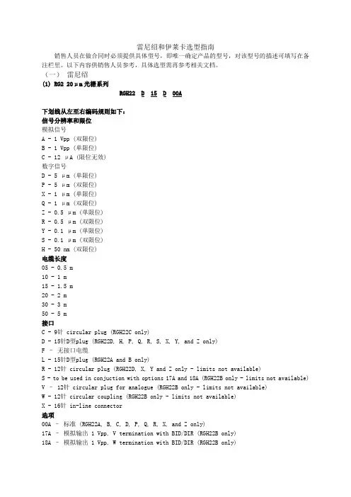
雷尼绍和伊莱卡选型指南销售人员在做合同时必须提供具体型号,即唯一确定产品的型号,对该型号的描述可填写在备注栏里。
以下内容供销售人员参考,具体选型需再参考相关文档。
(一)雷尼绍(1)RG2 20μm光栅系列RGH22 D 15 D 00A下划线从左至右编码规则如下:信号分辨率和限位模拟信号A - 1 Vpp (双限位)B - 1 Vpp (单限位)C - 12 μA (限位无效)数字信号D - 5 μm (单限位)P - 5 μm (双限位)X - 1 μm (单限位)Q - 1 μm (双限位)Z - 0.5 μm (单限位)R - 0.5 μm (双限位)Y - 0.1 μm (单限位)S - 0.1 μm (双限位)H - 50 nm (双限位)电缆长度05 - 0.5 m10 - 1 m15 - 1.5 m20 - 2 m30 - 3 m50 - 5 m接口C - 9针 circular plug (RGH22C only)D - 15针D型plug (RGH22D, H, P, Q, R, S, X, Y, and Z only)F –无接口电缆L - 15针D型plug (RGH22A and B only)R - 12针 circular plug (RGH22D, X, Y and Z only - limits not available)S - to be used in conjuction with options 17A and 18A (RGH22B only - limits not available) V – 12针 circular plug for analogue (RGH22B only - limits not available)W - 12针 circular coupling (RGH22B only - limits not available)X - 16针 in-line connector选项00A –标准 (RGH22A, B, C, D, P, Q, R, X, and Z only)17A –模拟输出 1 Vpp, V termination with BID/DIR (RGH22B only)18A –模拟输出 1 Vpp, W termination with BID/DIR (RGH22B only)20A - 3-state error annunciation (RGH22D, P, Q, R, X and Z only)61A - 20 MHz customer clock, (RGH22Y, S, and H only)62A - 10 MHz customer clock, (RGH22Y, S, and H only)63A - 5 MHz customer clock, (RGH22Y, S, and H only)(2) RG4 40μm光栅系列RGH41 B 15 L 00A下划线从左至右编码规则如下:信号分辨率和限位模拟输出A - 1 Vpp (双限位version)B - 1 Vpp (单限位version)数字输出T - 10 μmD - 5 μmG - 2 μmX - 1 μmN - 0.4 μmW - 0.2 μmY - 0.1 μmH - 50 nm电缆长度05 - 0.5 m10 - 1 m15 - 1.5 m30 - 3 m50 - 5 m接口D - 15针D型 plug (RGH41D, G, H, N, T, W, X and Y only)F –无接口电缆L - 15针D型plug (RGH41A and B only)S - to be used in conjunction with option 17A and 18A (RGH41B only -limits not available) V - 12针 circular plug for analogue (RGH41B only - limits not available)W – 12针 circular coupling (RGH41B only - limits not available)X – 16针 in-line connector选项00A–模拟输出 1 Vpp (RGH41A and B only)03A–数字输出, 单限位, differential alarm signal (RGH41D, G, T and X only)04A-数字输出, 单限位, 3 state alarm signal (RGH41D, G, T and X only)05A-数字输出, 双限位, single ended alarm signal (RGH41D, G, T and X only)06A-数字输出, 双限位, 3 state alarm signal (RGH41D, G, T and X only)17A–模拟输出 1 Vpp, V termination with BID/DIR (RGH41B only)18A-模拟输出1 Vpp, W termination with BID/DIR (RGH41B only)61–20 MHz customer clock (RGH41H, N, W and Y only)62–10 MHz customer clock (RGH41H, N, W and Y only)63–5 MHz customer clock (RGH41H, N, W and Y only)(二)伊莱卡产品(1)GS212光栅尺C 1 2 0-5 B –xxxx下划线从左至右编码规则如下选项:D=数显(±10um Accuracy); C=数控(±5um Accuracy)信号输出方式:1=RS422; 2=1Vpp; 3=11uA(DRO only)气压过滤:2=无气压; 3=有气压接口形式: 0=EMS 9D 带铠装; A=EMS 9D 无铠装,PUR(***较常用)3=Acu-rite 9D with armour; A=Acu-rite 9D with PUR4=Fanuc Honda with armour; E=Fanuc Honda with PUR5=HH 15D (female)with armour; F=HH 15D (female)with PUR 分辨率: 1=0.1um; 2=0.5um; 3=1um; 5=5um; 6=10um栅距: B=40um Grating period测量长度:xxxx=Travel in 10mm steps(如0100=1000mm)(2) MG232封闭式磁栅尺D 1 H 0-5 2 –xxxx下划线从左至右编码规则如下选项:D=数显(±10um Accuracy)信号输出方式:1=RS422安装: H:仿海德汉某型号安装尺寸。

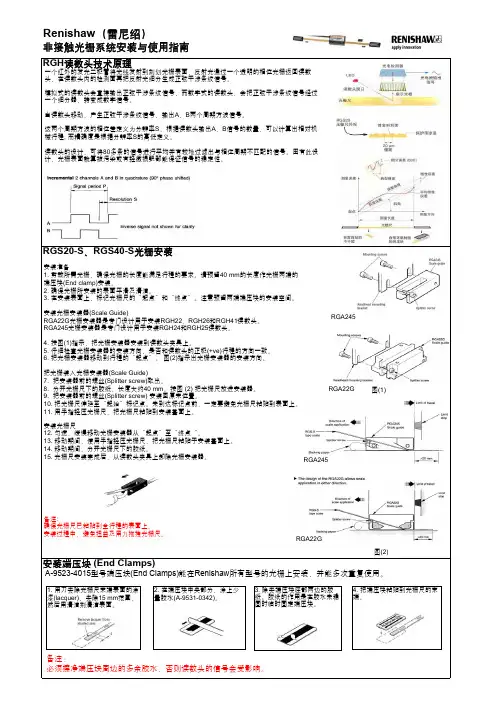
非接触光栅系统安装与使用指南RGS20-S 、RGS40-S 光栅安装Renishaw (雷尼绍)安装准备1. 剪裁所需光栅,确保光栅的长度能满足行程的要求。
请预留把光栅尺伸延至“起始”标记点。
未到达标记点前,一定要避免光栅尺粘贴到表面上。
确保光栅尺已粘贴到全行程的表面上。
图(1)图(2)备注:必须擦净端压块周边的多余胶水,否则读数头的信号会受影响。
所有型号的光栅上安装,并能多次重复使用。
RGA22GRGA245RGA245RGA22G读数头安装读数头设定图(3)图(3)是一个简单安装支架设计。
螺丝(A) ---- 夹紧读数头,设定Pitch 参数螺丝(B) ---- 设定Yaw 参数和偏移螺丝(C) ---- 可设定Roll 参数安装支架设定固定读数头的托架,必须有平坦表面,能满足读数头安装上的机械公差。
其次必须能调节读数头高度并有足够的稳定性,以预防在读数头工作期间所受到的所有外界影响。
为了减少光栅的安装问题,在未使用光栅安装器(Scale Guide)粘贴光栅前,请先把机械托架的Roll 参数和Yaw 参数调节到读数头的误差范围内,可使用clock gauge 或precision square 完成设定。
对于RGH22、RGH26和RGH41,设定读数头的高度,可透过蓝色和或橙色的校准胶片放置于读数头和光栅尺之间,读数头的LED 安装指示灯显示绿色,表示安装正确。
橙色的校准胶片还可以帮助设定读数头相对于光栅尺的偏移和Yaw 参数 。
对于RGH24和RGH25读数头,设定只可透过蓝色校准胶片放置于读数头和光栅尺之间, 读数头的LED 安装指示灯显示绿色,表示安装正确。
读数头高度设定完成后,以缓慢的速度移动读数头,确保读数头的指示灯在光栅尺的整个行程内都保持绿色。
RGB25和RGH41提供外置设定信号 (X 或Vx),当LED 指示灯失效时,可提供另一个安装参考。
外置设定信号是一个5 V 电源,信号为5 V 表示设定正确,当信号为0 V 时,表示需重新设定。


SWITCHBACK22Failure to follow installation and maintenance instructions detailed in this manual may result in serious personal injury and damage to the firearm. Do not attempt to use this product unless you have specific training and experience in the use of firearms.Because suppressed firearms make less noise than unsuppressed firearms, it is easy to forget that they are still firearms and capable of causing bodily injury and property damage. Remember, a suppressed firearm should be treated with the same safety and caution as an unsuppressed firearm.Firearm silencers are user-attached firearm muzzle devices, and as such are subject to improper attachment issues unless the procedures outlined in this manual are followed precisely.Before installing the silencer from the host firearm, be sure that the firearm is unloaded and the action is opened so that the firearm is visibly clear of any ammunition. If you are at all unsure as to the proper procedures to ensure that your firearm is unloaded, please consult your firearm user’s manual/instructions and/or contact a properly licensed dealer or the manufacturer of your firearm.Check the fit between barrel and silencer before firing! The thread mount must be fully shouldered on the barrel. There should be no visible gap between the barrel shoulder and the face of the silencer thread mount. If there is any gap DO NOT fire the host with the silencer attached. Poor accuracy and product damage may result if the silencer is not fully shouldered.CONTINUED ON NEXT PAGEWARNINGSilencers must be free of obstructions such as mud, dirt, etc. DO NOT attempt to shoot through an obstructed silencer.The silencer is designed to suppress the initial muzzle blast and subsequent projectile de-corking pressure. The silencer doesn’t contact or otherwise interact with the bullet, allowing the projectile to travel at its default speed. Because of this, a sonic crack may be produced by the projectile as it breaks the sound barrier.Depending on the geography of the area, the sonic crack may vary in volume. This is solely a function of the projectile breaking the sound barrier and is not related to product performance.To ensure your silencer remains secure while firing, it is of the utmost importance that you frequently verify the silencer is securely tightened onto the barrel. We recommend checking the security of the attachment after 30 discharges of the firearm.Before removing the silencer from the host firearm, be sure that the firearm is unloaded and the action is opened so that it is visibly clear of any ammunition. When removing the silencer, use extreme caution as it may be hot to the touch after firing. Use gloves to avoid burns or other injuries. Once the silencer is removed from the host firearm, SilencerCo recommends using a thread protector or other muzzle device to protect the muzzle threads and crown, during storage or transport.CONTINUED WARNINGThe Switchback 22 is the most versatile rimfire silencer ever developed. Not only does its modular construction allow the end user to choose from three lengths, but its long configuration can be optimized for either a pistol or rifle host.Inspired by technology used in rocket diffusers, the modular baffles of the Switchback 22 are highly configurable. Arrange your Switchback 22 in the short pistol silencer configuration, or flip the baffles in the long configuration for industry-leading rimfire rifle sound suppression. The Switchback 22 delivers the quality and versatility you have come to expect from SilencerCo’s premium rimfire silencers including compatibility with a variety of cartridges, durability, user serviceability, and our industry leading lifetime warranty and customer service.Due to the notoriously harsh nature of rimfire ammunition, this product features CTA™ (Click Together Assembly) baffles to ensure the suppressor remains easy to clean—even after long days at the range.The Switchback 22 mounts on conventional 1/2 X 28 (Class 3A) threads .400˝ in length.OVERVIEWP A R T SSHORT / REAR OUTER TUBEBACK CAP BLAST BAFFLE BLAST BAFFLE LIPFRONT / LONG OUTER TUBEFRONT CAPCOUPLER BAFFLEBAFFLE STACKBAFFLE STACK LIPThe Switchback 22 comes standard with (2) wrenches, (1) size 13 Viton O-ring already installed, as well as this field manual. Also included is (1) thread spacer. The thread spacer is to be used on threads .600 –.650.CALIBERS & RESTRICTIONS.22 LR (Only Caliber Approved for Full Auto) .17 Win Super Mag .17 HMR.22 WMR (.22 Win Mag).22 Hornet 5.7 X 28MATERIALSBaffles, Front Cap, & End Cap — Stainless Steel Tube —Titanium DIAMETER 1.07”MEDIUMSHORTLONG DEFAUL TRIFLE OPTIMIZEDINCLUDEDSHORT LONG 3.2 OZ6.5 OZ2.50”5.75”1AAltering configurations of the Switchbackmay include tightening and loosening ofseveral threaded parts.All threads are standard right-hand. Whentightening, snug the parts together slightlymore than hand-tighten pressure. Don’t overtighten.To tighten, seat a spanner wrench on thesilencer body with your left hand, and theother in your right hand on the part you wishto tighten (back cap, front cap, or couplerbaffle). Push the handles of the two spannerwrenches towards each other. (1A)THREADING&UNTHREADINGASSEMBLY&MODULARITYTo loosen, seat the spanner wrench in your left hand on the part you wish to unthread, and your right hand on the silencer body. Push the handles of the two spanner wrenches towards each other. (1B )1B Thread tubes into coupler baffle with the baffle cone toward the short (rear) outer tube as seen to the right (2A ). Lipped ends (2B ) of outer tubes face inward towards the coupler baffle for easy baffle alignment in next step. Gently snug the outer tubes and coupler baffle together with the provided wrenches before inserting any baffles. Excessive force is not necessary.Assemble 2 standard baffles (2C ), and a blast baffle as seen to the right. Notice there are notches on the baffles which keep the ports on the baffles in line with each other.2A2B 2CD E F A U L T C O N F I G U R A T I O NTHREADING & UNTHREADINGCOUPLER BAFFLELIPA S S E MB L Y & M O D U L A R I T YA SSEMBLY & MODUL ARITYDEFAULT CONFIGURATIONSlide the baffles from step 2 into the short tube oriented as seen in the image to the left (2C ).For best sound performance, align the cutouts of the baffle stack with the cutout of the coupler baffle. This is done visually, as there is no physical alignment feature on the coupler baffle. Seal the baffles inside with your serialized back cap. Gently tighten with your provided wrenches.2CIn similar fashion, assemble the remaining blast baffle, and baffles oriented as seen to the right. (2D ) Insert the baffle stack into the front tube, again visually aligning the cutouts to the coupler baffle for best performance. Gently tighten the front cap down with provided wrenches. 2DA SSEMBLY & MODUL ARITYBLAST BAFFLEBAFFLE STACKD E F A U L T C O N F I G U R A T I O NA S S E MB L Y & M O D U L A R I T YREADY FOR USESHORT CONFIGURATIONM E D I U M C O N F I G U R A T I O NUsing only the short outer tube, thread your serialized back cap on one side, and front cap on the other with the baffles oriented as shown on the left (3A ). Tube orientation (which side the lip is on) does not matter in this configuration. 3A4AUsing only the long outer tube, thread your serialized back cap on one side, and front cap on the other with the baffles oriented as shown on the right (4A ). Tube orientation (which side the lip is on) does not matter in this configuration.A SSEMBLY & MODUL ARITYA S S E MB L Y & M O D U L A R I T YREADY FOR USE READY FOR USERIFLE OPTIMIZED CONFIGURATIONA s s e m b l y i s t h e s a m e a s D e f a u l tConfiguration with the forward bafflesection reversed as shown to the left. (5A)For optimum performance, align baffle torear tube baffles, although this is far lessimportant in this optimized configuration.You may also remove the front cap and flipthe entire front module (long outer tubewith the baffles inside) to avoid touchinglead if internals are already fouled (5B).Replace the front cap and tighten gentlywith provided wrenches. The cutouts maynot align, which is ok in this configuration.5A5BThe user-serviceable nature of the Switchback 22 makes cleaning quick and simple. Itis recommended to clean the Switchback 22 every 1,000 rounds. Cleaning should alsobe performed when switching between .22 LR and 5.7x28mm or after the silencer hasbeen shot with an ablative media. The Switchback 22 internal components (not the outertubes) can be cleaned using solvents, ultrasonic tanks, light abrasive media, or certainchemical dips.The majority of fouling in 22 suppressors is lead and is highly toxic. Severehealth problems can result from lead entering the body not only from ingestion (e.g.,eating with exposed hands after handling lead), or even simple acts such as rubbing youreyes after handling ammunition. Exercise extreme caution when cleaning yourCONTINUED ON NEXT PAGE ASSEMBLY & MODULARITYREADY FOR USEMAINTENANCEWARNINGsuppressor, as you will be handling a substantial amount of lead. Wear nitrile gloves and wear protective eyewear at all times, handle your components in a secure area, and thoroughly wash your hands with soap and cold water immediately after handling.OUTER TUBESIt is not recommended to blast, dip, or ultrasonic clean the outer tubes, as it may damage them. Due to the self containing/sealing baffles no significant fouling should be present inside the outer tubes. The outer tubes can be easily cleaned or wiped out with a soft brush with plastic bristles, paper towel, or rag. There may be trace lead buildup on the internal diameter of the lip of the silencer outer tubes which can easily be broken off and removed by hand, or cleaned off with a soft brush with plastic bristles.CONTINUED ON NEXT PAGEBAFFLES, FRONT CAP, & BACK CAPDisassemble the Switchback 22 as listed in the instructions and clean using the following suggested products. Dry all components thoroughly before reassembling. If using a water-based cleaner, be sure to lightly coat the baffles with oil or other corrosion-resistant product after cleaning.SCRUBBINGVarious gun cleaning solvents and general CLP (cleaner/lubricant/protectant) gun oils can be used to help break up the fouling on your baffles. Utilizing a nylon brush, q-tips, and rags or paper towels, etc, you can successfully clean your baffles with some time scrubbing. Don’t use hard metal tools to scrape lead and carbon off your components as you may damage the metal. Abide by the safety precautions previously mentioned in this manual regarding lead at all times. Dispose of leaded materials in accordance with your local laws.MAINTENANCEBLASTINGBlasting with soda media is an excellent way to clean baffles and other components. A blast cabinet or handheld soda blaster is required for this method. DO NOT blast parts with glass bead, aluminum oxide, or other hard media; this will etch and damage your components. Note that your media will become exposed to lead during this process. Good containment, ventilation, gloves, and a breathing mask should be used to protect yourself and those around you from lead particulates that become airborne. Dispose of contaminated blast media appropriately and in accordance with local, state, and federal regulations.DIPParacetic Acid (AKA “The Dip”) is an off-the-shelf 50/50 mix of 3% hydrogen peroxide and 5% acidity distilled white vinegar. It can be used to clean baffles and other stainless steel components very effectively, as it actually dissolves lead.CLEANING OPTIONSCONTINUED ON NEXT PAGEDo not use this on your Titanium Switchback tubes, as it will cause corrosion. When Paracetic Acid reacts with lead, it results in Lead Acetate. This is toxic and is easily absorbed through exposed skin. Eye protection and impermeable gloves (such as disposable Nitrile gloves) must be worn at all times.Simply let your fouled baffles soak in the mix. No scrubbing is needed. A glass jar or other chemical resistant container should be used to hold everything, as it is not only toxic, but very corrosive as well. Keep it in a well ventilated area away from any children, pets, or anyone/anything else that could otherwise come in contact with it.Check on the components every few hours, or overnight, until the lead has been dissolved and your baffles are clean. Carefully remove the components and rinse them off with clean water. Allow to dry and reassemble.MAINTENANCEWARNINGThe resulting Paracetic Acid/Lead Acetate mix must be disposed of carefully and appropriately, in accordance with all local regulations. Contact your local waste disposal establishment for instructions on HAZMAT (hazardous material). Usually it is as simple as dropping it off at your local waste disposal establishment. Do not dump it down the drain or dump it outside. It is very nasty stuff that is not only very toxic, but also corrosive and can potentially damage plumbing, or anything else it comes in contact with.ULTRASONIC CLEANINGUltrasonic cleaning is a 50/50 mix of water and “Purple Power” cleaner and works very well for cleaning baffles. This method is not recommended for use on the outer tubes. Note that this solution will contain lead. Dispose of appropriately and in accordance with local, state, and federal regulations. DO NOT dump it down the drain or outside.CLEANING OPTIONS CONTINUEDWe proudly stand behind the quality of our products with a lifetime warranty, no matter what—even if it’s not a product defect. Our 48 hour repair turnaround even warranties stupid… once. If you experience any issues, please refer to the SUPPORT section of our website or contact our Customer Service team at ******************* or 801.417.5384.If your silencer has a defect in manufacturing or materials, there will be no charges for service or replacement through our SilencerCo facility. If we determine that a claim is not covered under warranty, a discounted replacement option will be granted.MAINTENANCEW A R R A N T YThis warranty does not cover damage to the silencer or host firearm resulting from careless or irresponsible handling, adjustments or modifications to design, negligence, or other abuse. SilencerCo assumes no liability for unsafe or illegal use of the silencer by its purchaser or any other user that comes in contact with the product after purchase. SilencerCo assumes no responsibility for physical injury or property damage resulting from careless or irresponsible handling or by any use contrary to the recommendations, warnings, and cautions generally listed in this manual. SilencerCo does not cover damage to the silencer or host firearm resulting from improper hand-loaded or reloaded ammunition or defective ammunition.Register your SilencerCo product online at any time to activate your lifetime warranty The American Suppressor Association fights to protect and expand your silencer rights. Join the fight today!CONTINUEDWARR ANTYR E G I S T R A T I O N/REGISTER。
RH-222产品说明书v1.1物品清单小心打开包装盒,检查包装盒里面应有以下配件:主机(1)天线(1)充电器(1)车充(1)对讲耳机(1)合格证(1)保修卡(1)注:括号中数字表示设备数量如果发现有所损坏或者任何配件短缺的情况,请及时和经销商联系。
目录第一章用户手册简介 (2)第二章产品概述 (2)2.1产品简介 (2)2.2 产品型号说明 (2)2.3主要功能及特点 (2)2.3.1基本功能 (3)2.3.2 压缩处理功能 (3)2.4 主要应用 (3)第三章硬件安装 (3)2.1注意事项 (3)3.2 面板说明 (4)3.2.1 主机前面板 (4)3.2.2 主机底面板 (4)3.2.3 主机上面板 (5)3.2.4 指示灯 (5)3.3.2 充电 (5)附录 1 (6)附录 2 (8)附录 3 (8)第一章用户手册简介感谢您购买RH-222系列视频服务器!在您准备使用本产品之前,请先仔细阅读本手册,以便能更好的使用本产品的所有功能。
本手册的用途是帮助您熟悉和正确的使用RH-222系列视频服务器第二章产品概述2.1产品简介目前,公检法、抢修、环保、保险定损、水利、电力、铁路、公路等行业对移动监控都有各自需求,传统监控设备无法满足相应需求。
数码相机、DV等设备虽然能在一定程度上实现移动记录、现场取证的工作,却无法实现数据的实时上传。
随着3G技术的发展与应用,无线网络的带宽得到了大幅提升,高质量的视频图像传输变为了可能。
在这种背景下,本公司基于多年的安防行业沉淀,结合3G技术,推出便携式单兵监控系统。
该系统还可以与中研瑞华自主研发的“3GGPS”监控平台实现对接,为用户提供更加丰富的特色功能。
2.2 产品型号说明2.3主要功能及特点1路视频,音频输入,视频分辨率最高支持D1(704*576)分辨率编码,支持GPS定位,支持3G无线传输,支持SD卡存储。
2.3.1基本功能视频压缩技术:采用H.264视频压缩技术及OggVorbis音频压缩技术,压缩比高,且处理非常灵活。
Series RH-R Humidity Transmitter is the ideal transmitter for those applications where space is limited. The compact sensor is protected by a removable filter. It can be mounted up to 16 feet away from the weatherproof base. The Series RH-R is ideal for environmental chambers, rubber bladder burst detection systems and air handler Disconnect power supply before installation to prevent electrical shock andMake sure all connections are in accordance with the job wiring diagram and in accordance with national and local electrical codes. Use copper conductors only.Do not make changes to the cable lengths. Sensors are factory calibrated for supplied length of cable. Optional lengths are available from the factory.Use electrostatic discharge precautions (e.g., use of wrist straps) during installation and wiring to prevent equipment damage.Avoid locations where severe shock or vibration, excessive moisture or corrosive may result. The Series RH-R Humidity Transmitter was not designed for AC voltage operation.Printed in U.S.A. 8/19FR# 443339-30©Copyright 2019 Dwyer Instruments, Inc.OSA (Outside Air)The transmitter should be mounted under an eave, shield, or in an area that is out of the elements or direct sunlight.1. Remove the cover plugs from the face of the unit and the top cover.2. Position the transmitter where it is to be mounted and mark the mounting holes in each corner of the housing.3. Drill or punch out marked locations.4. Place the transmitter box over mounting holes on wall and align. Install wall mount screws (not provided) in mounting holes.5. Proceed with wiring according to Figure 2.6. Replace cover and cover plugs on the face of the unit.WIRINGUse maximum 18 AWG wire for wiring terminals. Refer to Figure 1 for wiring information.4-20 mA Output Models4-20 mA output units may be powered with a 10-35 VDC supply. The following describes the proper wiring of these transmitters with mA output.The Series RH-R transmitter is designed as a two-wire 4-20 mA device with two channels. The channels are common on the positive side of the current loops. Sensor excitation power is derived from the relative humidity channel, so power must always be applied to that channel. If the temperature channel is not equipped or used, it can be left disconnected. The basic two-wire connection is shown in Figure 1.Note: For models with RH and temperature, the RH output must be hooked up. If the RH outputs is not required, wire the “_” terminal of the power supply to terminal 1.Figure 1Checkout1. Verify that the unit is mounted in the correct position.2. 4-20 mA Models:Verify appropriate supply voltage. The transmitter requires a minimum of 10 and a maximum of 35 VDC at its connection for proper operation. Choose a power supply with a voltage and current rating which meets this requirement under all operating conditions. If the power supply is unregulated, make sure voltage remains within these limits under all power line conditions. Ripple on the supply should not exceed 100 mV.Loop Resistance – The maximum allowable loop resistance depends on the power supply voltage. Maximum loop voltage drop must not reduce the transmitter voltage below the 10 VDC minimum. Maximum loop resistance can be calculated with the following equation. Vps is the power supply voltage.Some receivers, particularly loop powered indicators, may maintain a fixed loop voltage to power the device. This voltage drop must also be subtracted from the power supply voltage when calculating the voltage margin for the transmitter. The following equation takes this into account. Vrec is the receiver fixed voltage.MAINTENANCEUpon final installation of the Series RH-R Temperature/Humidity Transmitter and the companion receiver, no routine maintenance is required. A periodic check of the system calibration is recommended. The Series RH-R is not field serviceable and should be returned if repair is needed (field repair should not be attempted and may void warranty). Be sure to include a brief description of the problem plus any relevant application notes. Contact customer service to receive a return goods authorization number before shipping.V ps -10.020 mARmax =V ps -10.0-V rec 20 mARmax =TEMPERATURE RECEIVER。
非接触光栅系统安装与使用指南
RGS20-S 、RGS40-S 光栅安装
(End Clamps)
Renishaw (雷尼绍)
安装准备
1. 剪裁所需光栅,确保光栅的长度能满足行程的要求。
请预留把光栅尺伸延至“起始”标记点。
未到达标记点前,一定要避免光栅尺粘贴到表面上。
确保光栅尺已粘贴到全行程的表面上。
安装过程中,避免扭曲及用力拖拽光栅尺。
图(1)图(2)
除去端压块底部两边的胶纸。
胶纸的作用是在胶水未稳固时临时固定端压块。
4. 把端压块粘贴到光栅尺的末端。
备注:
必须擦净端压块周边的多余胶水,否则读数头的信号会受影响。
型号端压块(End Clamps)所有型号的光栅上安装,并能多次重复使用。
RGA22G
RGA245
RGA245RGA22G。
Installation guideM-9531-9818-01-EContentsProduct compliance 1 Storage and handling 2 RGH22 readhead installation drawing 3 RGS20 scale installation drawing 4 Scale application 5 End clamps 5 Reference mark and limit switch actuator installation 6 Readhead mounting and alignment 6 Reference mark set-up 7 Limit switch 7 Output signals 7 Speed 8 Electrical connections 9 Output specifications 10 General specifications 12 Scale specifications 12Product complianceCRenishaw plc declares that RGH22 complies with the applicable standards and regulations. A copy of the EU Declaration of Conformity is available from our website at /productcompliance .FCC complianceThis device complies with part 15 of the FCC Rules. Operation is subject to the following two conditions: (1) This device may not cause harmful interference, and (2) this device must accept any interference received, including interference that may cause undesired operation.The user is cautioned that any changes or modifications not expressly approved by Renishaw plc or authorised representative could void the user’s authority to operate the equipment.This equipment has been tested and found to comply with the limits for a Class A digital device, pursuant to part 15 of the FCC Rules. These limits are designed to provide reasonable protection against harmful interference when the equipment is operated in a commercial environment. This equipment generates, uses, and can radiate radio frequency energy and, if not installed and used in accordance with the instruction manual, may cause harmful interference to radio communications. Operation of this equipment in a residential area is likely to cause harmfulinterference in which case the user will be required to correct the interference at his own expense.NOTE: This unit was tested with shielded cables on the peripheral devices. Shielded cables must be used with the unit to ensure compliance.Further informationFurther information relating to the RGH22 encoder range can be found in the RGH22 encoder system Data sheet (Renishaw part no. L-9517-9676). This can be downloaded from our website at /opticalencoders and is also available from your local representative.This document may not be copied or reproduced in whole or in part, or transferred to any other media or language, by any means without the written prior permission of Renishaw. The publication of material within this document does not imply freedom from the patent rights of Renishaw plc.DisclaimerRENISHAW HAS MADE CONSIDERABLE EFFORTS TO ENSURE THE CONTENT OF THIS DOCUMENT IS CORRECT AT THE DATE OF PUBLICA TION BUT MAKES NO WARRANTIES OR REPRESENTATIONS REGARDING THE CONTENT . RENISHAW EXCLUDES LIABILITY ,HOWSOEVER ARISING, FOR ANY INACCURACIES IN THIS DOCUMENT.The use of this symbol on Renishaw products and/or accompanying documentation indicates that the product should not be mixed with general household waste upon disposal. It is the responsibility of the end user to dispose of this product at a designated collection point for waste electrical and electronic equipment (WEEE) to enable reuse or recycling. Correct disposal of this product will help to save valuable resources and prevent potential negative effects on the environment. For more information, please contact your local waste disposal service or Renishaw distributor.The packaging of our products contains the following materials and can be recycled.REACH regulationInformation required by Article 33(1) of Regulation (EC) No. 1907/2006 (“REACH”) relating to products containing substances of very high concern (SVHCs) is available at /REACH .Storage and handling N-heptane Propan-2-ol CH 3CHOHCH Chlorinated Solvents OperatingSystem +55 °C 0 °C95% relative humidity (non-condensing)to BS EN 60068-2-78:2013*Dimensions measured from substrate. †Alternative mounting faces‡The recommended thread engagement is 5 mm. The recommended tightening torque is between 0.5 and 0.7 Nm.NOTE: The surface roughness of the scale mounting surface must be ≤ 3.2 Ra.The parallelism of the scale surface to the axis of motion (readhead rideheight variation) must be within 0.05 mm.Optional bolted reference mark actuator (A-9531-0287)End clampsA-9523-4015 is an end clamp kit designed to be used with Renishaw RGS scale.IMPORTANT: End clamps should be used to ensure positional stability of the scale and reference mark repeatability.NOTE: End clamps can be mounted before or after readhead installation.Ensure that excess glue is wiped away from scale as it may affect the readhead signal level.The end clamp features two small regionsof contact adhesive. These will temporarily hold the end clamp in position while the glue cures. Remove the backing tapefrom either side.Remove the lacquer coating from thelast 15 mm of each end of the scale with a knife and clean with one ofImmediately position end clampover the end of the scale. Allow 24 hours at 20 °Cfor full cure.Thoroughly mix up a sachet of glue(A-9531-0342) and apply a small amount to the underside of the end clamp.RGA22G - scale applicator (recommended for shorter axes or where space is limited)The RGA22G scale applicator (A-9531-0239) is designed specifically for installing RGS20-S scale for use withthe RGH22 readhead.Allow scale to acclimatize to installation environment prior to installation.Mark out ‘START’ and ‘FINISH’ points for the scale on the axis substrate. Ensure that there is room for theend clamps (see ‘RGS20 installation drawing’).Thoroughly clean and degrease the substrate using recommended solvents (see 'Storage and handling').Allow substrate to dry before applying scale.Mount the scale applicator to the readhead mounting bracket using M3 screws. Place the shim suppliedwith the readhead between the applicator and substrate to set the nominal height.NOTE: Scale applicator can be mounted either way roundto enable easiest orientation for scale installation.Move axis close to scale start position, leaving enough room for the scale to be inserted through theapplicator, as shown below.‘START’ point (as shown). Ensure backing tape is routed under the splitter screw.Scale applicationRGA22 - scale applicator (recommended for longer axes)The RGA22 scale applicator kit (A-9531-0265) is designed specifically for installing RGS20-S scale for use with the RGH22 readhead. For instructions on how to use the RGA22 please refer to the ‘RGA22 scale applicator User’s guide’ (M-9531-0297).Slowly and smoothly move the applicator through the entire axis of travel, ensuring the backingpaper is pulled manually from the scale and does not catch under the applicator.Remove applicator and, if necessary, adhere the remaining scale manually.Apply firm finger pressure via a clean lint-free cloth along the length of the scale after application to ensure complete adhesion.Clean scale using Renishaw scale cleaning wipes (A-9523-4040) or a clean, dry, lint-free cloth. Fit end clamps (see ‘End clamps’ section).Allow 24 hours for complete adhesion of scale before fitting reference mark and limit magnets.Apply finger pressure to the scale at the ‘START’ point, using a clean lint-free cloth, to ensure scale endadheres well to the substrate.ART’ pointReference mark and limit switch actuator installationbut within the limits specified by the relevant installation drawing.Ensure that excess glue does not enter the reference mark actuator adjustment mechanism.Single limit switchesFor single limit switch detection, limit switch actuator should be mounted with the dimple uppermost.Dual limit switchesSome versions of the RGH22 are configured to detect dual limit switch actuators.NOTE: Refer to RGH22 installation drawing for limit switch actuator positioning.Reference mark actuatorsReference marks provide a repeatable ‘datum position’ for the readhead.Actuators are available in either bolted or glued formats (see below)Limit switch actuatorsThere are several different size limit switch actuators available:50 mm limit switch actuator24.4 mm limit switchactuator10 mm limit switch actuator A-9531-0250Epoxy-mountedreference mark actuatorA-9531-0287Screw-mountedreference mark actuatorReadhead mounting and alignmentMounting bracketsThe bracket must have a flat mounting surface and should provide adjustment to enable conformance to the installation tolerances, allow adjustment to the rideheight of the readhead, and be sufficiently stiff to prevent deflection or vibration of the readhead during operation.Readhead set-upEnsure that the scale, readhead optical window and mounting face are clean and free from obstructions. To set nominal rideheight, place the blue or orange spacer with the aperture directly under the optical centre of the readhead to allow normal LED function during set-up procedure. The orange spacer also helps to position readhead with respect to offset and yaw relative to the scale NOTE: Ensure readhead fixing screws are tightened to 0.5 Nm - 0.7 Nm.Adjust the readhead to achieve a solid Green LED. When correctly installed the set-up LED remains Green along the full axis of travel.An external set-up signal (X or V X ) is also available on RGH22 readheads for use where the LED is notorReference mark set-upT o ensure unidirectional repeatability, the reference mark requires phasing with the scale in the direction of normal datuming operation.A reference pulse is output in both directions, but repeatability is guaranteed only in the phased direction. The readhead should be set up correctly ensuring a green LED indication over the full length of travel. The reference mark actuator should be installed as shown on the installation drawing.NOTE: It is recommended that a datum procedure is performed as part of any power-up sequence to ensure the correct datum position is recorded.NOTE: Reference mark output is synchronised with the incremental channels, giving unit of resolution pulse width. For further details see RGH22 encoder system Data sheet (Renishaw part no. L-9517-9676).Phasing procedureThe readhead must be moved over the reference mark in the direction to be used for the datuming operation. The reference mark is phased correctly when the set-up LED flashes red for 0.25 seconds. If it flashes orange or goes blank, the reference mark adjuster screw should be turned anti-clockwise by 18turn and the procedure repeated until a red flash is obtained.D ual limit versions (RGH22P , Q, R, S and H) utilise the black wire (pin 11) as the P limit output.The ‘E’ alarm signal on these versions is only available at the orange wire as a single-ended E − output. Dual limit readheads are only available with F , D, or X terminations.AlarmFor RGH22D, X, Z, P , Q, R, - alarm asserted when signal amplitude < 15%.For RGH22Y , S, H - alarm asserted when: - Signal amplitude > 150% - Readhead exceeds specified maximum speed Also, outputs are 3-stated at signal amplitude < 15%Output signalsRGH22 D, X, Z, Y, H, P, Q, R, S, RS422A digital12-way circular plug (termination code R)15-way D-type plug (termination code D)Limit switchLimit switch detection is entirely independent of other readhead functions - the signal is only outputwhen the readhead is positioned over the limit switch actuator.In-line connector plug (termination code X)*Dual limit versions (RGH22A) utilise the clear wire (pin 7) as the V P limit output. The V X external set-up signal on theseversions is not available. Dual limit readheads are only available with F , L or X terminations. †Only connected with option 17 ††Only connected with option 18Output signals (continued)RGH22 A, B 1 Vpp analogue12-way circular coupling plug (termination code W)In-line connector plug (termination code X)‡Reference mark uni-directional operationThe RGH22 reference mark output is not repeatable in both directions. Certain controllers will flag an error when they see different reference mark positions in the forward and reverse directions.BID DIR pins allow the readhead to be configured to ignore the reference pulse output in the unphased direction (see section Reference mark set-up).Analogue readheadsRGH22A and B - 4 m/s (−3dB)SpeedDigital readheadsNon-clocked output readheadsClocked output readheadsThe RGH22Y , S, and H readheads are available with a variety of different clocked outputs. Customers must ensure they comply with the lowest recommended counter input frequency.BID/DIR connections12-way circular plug (termination code V)15-way D-type plug (termination code L)Electrical connections* IMPORTANT: The outer shield should be connected to the machine earth (Field Ground). The inner shield should be connected to 0 V . Care should be taken to ensure that the inner and outer shields are insulated from each other. If the inner and outer shields are connected together, this will cause a short between 0 V and earth, which could cause electrical noise issues.Recommended signal terminationDigital outputs - RGH22D, X, Z, Y, H, P , Q, R and SAnalogue output - RGH22 A, BV 0 V 1 V 2+V 0 V 1 V 2−ΩStandard RS422A line receiver circuitry.Capacitors recommended for improved noise immunity.†Only required on alarm channel E for fail safe operation.Limit output5 V - 25 VP Q V p V qSelect R so that maximum current does not exceed 20 mA. Alternatively, use a relay or opto-isolator.Output specificationsDigital output signals - type RGH22D, X, Z, Y, H, P, Q, R and SForm - Square wave differential line driver to EIA RS422A (except limit switches P, Q and external set-up signal X)Incremental†2 channels A and B in quadrature (90° phase shifted)Actuation device A-9531-0251, A-9531-2052 or A-9531-2054.*Dual limit available with flying lead, 15 pin D connector or in-line X connector only.†Inverse signals not shown for clarity.Limit open collector outputSingle limit RGH22D, X, Z, Y Dual limit RGH22P, Q, R, S, H*QAsynchronous pulse QBetween 50% and 70% signal level, X is aduty cycle.Time spent at 5 V increases with signal level.At > 70% signal level X is nominal 5 V.External set-up50%70%100%0signal level20 ms minimumEAlarmRGH22D, P, X, Q, Z and RAlarm output asserted when < 15% signalRGH22Y, S and HOptions 61, 62 and 63Single ended line driven output alarm asserted when > 150% signal or overspeed (RGH22S and H only).Differential line driver output alarm asserted when > 150% signal or overspeed (RGH22Y only).3-state output alarm asserted when < 15% signal.Line driven alarm output†E− only on dual limit readheads (RGH22P, Q, R, S and H only)3-state outputDifferentially transmitted signals forced open circuit for > 20 ms when alarm conditions valid.Asynchronous pulse P, QOutput specifications (continued)Analogue output signals - type RGH22B and A (1Vpp)Actuation device A-9531-0251, A-9531-2052 or A-9531-2054.Limit open collector outputSingle limit RGH22BDual limit RGH22AAsynchronous pulse V p V q< 0.1 mm typicalV Asynchronous pulse V qBetween 50% and 70% signal level, V X is a duty cycle.Time spent at 5 V increases with signal level. At > 70% signal level V X is nominal 5 V .External set-upvoltage at V X5 (nom)50%70%100%signal levelIncremental 2 channels V 1 and V 2 differential sinusoids in quadrature (90° phase shifted)Actuation device A-9531-0250 or A-9531-0037Length of actuating magnetGeneral specificationsPower supply 5 V ±5%120 mA (typical), 200 mA RGH22Y, S and HNOTE: Current consumption figures refer to unterminated readheads.For digital outputs a further 25 mA per channel pair (e.g. A+, A−) willbe drawn when terminated with 120 Ω.For analogue outputs a further 20 mA will be drawn when terminatedwith 120 Ω.Power from a 5 V dc supply complying with the requirements for SELVof standard IEC BS EN 60950-1.Ripple200 mVpp@frequency up to 500 kHz maximum.Temperature Storage−20 °C to +70 °COperating0 °C to +55 °CHumidity95% relative humidity (non-condensing) to EN 60068-2-78Sealing IP50Acceleration Operating500 m/s2, 3 axesShock Non-operating1000 m/s2, 6 ms, ½ sine, 3 axesVibration Operating100 m/s2 max @ 55 Hz to 2000 Hz, 3 axesMass Readhead45 gCable38 g/mCable12 core, double shielded, maximum diameter 4.7 mm.Flex life > 20 × 106 cycles at 50 mm bend radius.Renishaw encoder systems have been designed to the relevant EMC standards, but must be correctly integrated to achieve EMC compliance. In particular, attention to shielding arrangements is essential.Scale specificationsScale type Reflective gold plated steel tape with protective lacquer coating.Adhesive backing tape allows direct mounting to the machine substrate. Scale period20 µmLinearity±3 µm/mScale length Up to 50 m (> 50 m by special order)Form(H × W)0.2 mm × 6 mm (includes adhesive)Substrate materials Metals, ceramics and composites with expansion coefficientsbetween 0 and 22 µm/m/°C(steel, aluminium, Invar, granite, ceramic etc.)Coefficient of thermal expansion Matches that of substrate material when scale ends are fixed byepoxy mounted end clampsEnd fixing Epoxy mounted end clamps (A-9523-4015) using 2 part epoxyadhesive (A-9531-0342).Scale end movement typically < 1 µm up to +40 °C.Temperature Operating−10 °C to +120 °CMinimum installation10 °CStorage−20 °C to +70 °CHumidity95% relative humidity (non-condensing) to EN 60068-2-78Renishaw plcNew Mills, Wotton-under-Edge Gloucestershire, GL12 8JR United KingdomT +44 (0)1453 524524F +44 (0)1453 524901E ***************For worldwide contact details, please visit our main website at/contactPart no.: M-9531-9818-01-EIssued: 11.2019 *M-9531-9818-01*RENISHAW HAS MADE CONSIDERABLE EFFORTS TO ENSURE THE CONTENT OF THIS DOCUMENT IS CORRECT A T THE DATE OF PUBLICATION BUT MAKES NO WARRANTIES OR REPRESENTATIONS REGARDING THE CONTENT. RENISHAW EXCLUDES LIABILITY , HOWSOEVER ARISING, FOR ANY INACCURACIES IN THIS DOCUMENT .© 2001-2019 Renishaw plc. All rights reserved.Renishaw reserves the right to change specifications without notice.RENISHAW and the probe symbol used in the RENISHAW logo are registered trade marks of Renishaw plc in the United Kingdom and other countries. apply innovation and names and designations of other Renishaw products and technologies are trade marks of Renishaw plc or its subsidiaries.All other brand names and product names used in this document are trade names, trade marks or registered trade marks of their respective owners.。